EP2259477A2 - Hybrid ARQ method with signal constellation rearrangement - Google Patents
Hybrid ARQ method with signal constellation rearrangement Download PDFInfo
- Publication number
- EP2259477A2 EP2259477A2 EP10178347A EP10178347A EP2259477A2 EP 2259477 A2 EP2259477 A2 EP 2259477A2 EP 10178347 A EP10178347 A EP 10178347A EP 10178347 A EP10178347 A EP 10178347A EP 2259477 A2 EP2259477 A2 EP 2259477A2
- Authority
- EP
- European Patent Office
- Prior art keywords
- symbol
- bit
- bits
- data packets
- predetermined
- Prior art date
- Legal status (The legal status is an assumption and is not a legal conclusion. Google has not performed a legal analysis and makes no representation as to the accuracy of the status listed.)
- Granted
Links
- 238000000034 method Methods 0.000 title claims abstract description 27
- 230000008707 rearrangement Effects 0.000 title description 6
- 230000005540 biological transmission Effects 0.000 claims abstract description 103
- 238000004891 communication Methods 0.000 claims abstract description 19
- 238000012937 correction Methods 0.000 claims abstract description 6
- 238000013507 mapping Methods 0.000 claims description 80
- 238000013459 approach Methods 0.000 description 5
- 238000012935 Averaging Methods 0.000 description 4
- 230000015556 catabolic process Effects 0.000 description 3
- 238000006731 degradation reaction Methods 0.000 description 3
- 238000004364 calculation method Methods 0.000 description 2
- 125000004122 cyclic group Chemical group 0.000 description 2
- 230000011664 signaling Effects 0.000 description 2
- 238000007476 Maximum Likelihood Methods 0.000 description 1
- 239000000654 additive Substances 0.000 description 1
- 230000000996 additive effect Effects 0.000 description 1
- 238000004458 analytical method Methods 0.000 description 1
- 230000009286 beneficial effect Effects 0.000 description 1
- 230000003247 decreasing effect Effects 0.000 description 1
- 238000010586 diagram Methods 0.000 description 1
- 238000005516 engineering process Methods 0.000 description 1
Images




Classifications
-
- H—ELECTRICITY
- H04—ELECTRIC COMMUNICATION TECHNIQUE
- H04L—TRANSMISSION OF DIGITAL INFORMATION, e.g. TELEGRAPHIC COMMUNICATION
- H04L1/00—Arrangements for detecting or preventing errors in the information received
- H04L1/12—Arrangements for detecting or preventing errors in the information received by using return channel
- H04L1/16—Arrangements for detecting or preventing errors in the information received by using return channel in which the return channel carries supervisory signals, e.g. repetition request signals
- H04L1/18—Automatic repetition systems, e.g. Van Duuren systems
- H04L1/1812—Hybrid protocols; Hybrid automatic repeat request [HARQ]
- H04L1/1816—Hybrid protocols; Hybrid automatic repeat request [HARQ] with retransmission of the same, encoded, message
-
- H—ELECTRICITY
- H04—ELECTRIC COMMUNICATION TECHNIQUE
- H04L—TRANSMISSION OF DIGITAL INFORMATION, e.g. TELEGRAPHIC COMMUNICATION
- H04L1/00—Arrangements for detecting or preventing errors in the information received
- H04L1/0001—Systems modifying transmission characteristics according to link quality, e.g. power backoff
- H04L1/0002—Systems modifying transmission characteristics according to link quality, e.g. power backoff by adapting the transmission rate
- H04L1/0003—Systems modifying transmission characteristics according to link quality, e.g. power backoff by adapting the transmission rate by switching between different modulation schemes
-
- H—ELECTRICITY
- H04—ELECTRIC COMMUNICATION TECHNIQUE
- H04L—TRANSMISSION OF DIGITAL INFORMATION, e.g. TELEGRAPHIC COMMUNICATION
- H04L1/00—Arrangements for detecting or preventing errors in the information received
- H04L1/12—Arrangements for detecting or preventing errors in the information received by using return channel
- H04L1/16—Arrangements for detecting or preventing errors in the information received by using return channel in which the return channel carries supervisory signals, e.g. repetition request signals
- H04L1/18—Automatic repetition systems, e.g. Van Duuren systems
- H04L1/1812—Hybrid protocols; Hybrid automatic repeat request [HARQ]
-
- H—ELECTRICITY
- H04—ELECTRIC COMMUNICATION TECHNIQUE
- H04L—TRANSMISSION OF DIGITAL INFORMATION, e.g. TELEGRAPHIC COMMUNICATION
- H04L1/00—Arrangements for detecting or preventing errors in the information received
- H04L1/12—Arrangements for detecting or preventing errors in the information received by using return channel
- H04L1/16—Arrangements for detecting or preventing errors in the information received by using return channel in which the return channel carries supervisory signals, e.g. repetition request signals
- H04L1/18—Automatic repetition systems, e.g. Van Duuren systems
- H04L1/1812—Hybrid protocols; Hybrid automatic repeat request [HARQ]
- H04L1/1819—Hybrid protocols; Hybrid automatic repeat request [HARQ] with retransmission of additional or different redundancy
-
- H—ELECTRICITY
- H04—ELECTRIC COMMUNICATION TECHNIQUE
- H04L—TRANSMISSION OF DIGITAL INFORMATION, e.g. TELEGRAPHIC COMMUNICATION
- H04L27/00—Modulated-carrier systems
- H04L27/32—Carrier systems characterised by combinations of two or more of the types covered by groups H04L27/02, H04L27/10, H04L27/18 or H04L27/26
- H04L27/34—Amplitude- and phase-modulated carrier systems, e.g. quadrature-amplitude modulated carrier systems
-
- H—ELECTRICITY
- H04—ELECTRIC COMMUNICATION TECHNIQUE
- H04L—TRANSMISSION OF DIGITAL INFORMATION, e.g. TELEGRAPHIC COMMUNICATION
- H04L27/00—Modulated-carrier systems
- H04L27/32—Carrier systems characterised by combinations of two or more of the types covered by groups H04L27/02, H04L27/10, H04L27/18 or H04L27/26
- H04L27/34—Amplitude- and phase-modulated carrier systems, e.g. quadrature-amplitude modulated carrier systems
- H04L27/345—Modifications of the signal space to allow the transmission of additional information
- H04L27/3461—Modifications of the signal space to allow the transmission of additional information in order to transmit a subchannel
- H04L27/3472—Modifications of the signal space to allow the transmission of additional information in order to transmit a subchannel by switching between alternative constellations
Definitions
- the present invention relates to a hybrid ARQ retransmission method in a communication system.
- a common technique in communication systems with unreliable and time-varying channel conditions is to correct errors based on automatic repeat request (ARQ) schemes together with a forward error correction (FEC) technique called hybrid ARQ (HARQ). If an error is detected by a commonly used cyclic redundancy check (CRC), the receiver of the communication system requests the transmitter to resend the erroneously received data packets.
- ARQ automatic repeat request
- FEC forward error correction
- HARQ hybrid ARQ
- Types II and III schemes are obviously more intelligent and show a performance gain with respect to Type I, because they provide the ability to reuse information from of previously received erroneous packets.
- the reliabilities of the transmitted bits will increase linearly with the number and power of received packets. From a decoder point of view the same FEC scheme (with constant code rate) will be employed over all transmissions. Hence, the decoder does not need to know how many retransmissions have been performed, since it sees only the combined soft-decision values. In this scheme all transmitted packets will have to carry the same number of symbols.
- Code-combining concatenates the received packets in order to generate a new code word (decreasing code rate with increasing number of transmission). Hence, the decoder has to be aware of the FEC scheme to apply at each retransmission instant. Code-combining offers a higher flexibility with respect to soft-combining, since the length of the retransmitted packets can be altered to adapt to channel conditions. However, this requires more signaling data to be transmitted with respect to soft-combining.
- the identical code-symbols are combined using soft-combing as described in the section titled "Soft Combining" while the remaining code-symbols will be combined using code-combining.
- the signaling requirements will be similar to code-combining.
- bit reliabilities within soft-combined symbols will be in a constant ratio over all retransmissions, i.e. bits which have been less reliable from previous received transmissions will still be less reliable after having received further transmissions and, analogous, bits which have been more reliable from previous received transmissions will still be more reliable after having received further transmissions.
- the varying bit reliabilities evolve from the constraint of two-dimensional signal constellation mapping, where modulation schemes carrying more than 2 bits per symbol cannot have the same mean reliabilities for all bits under the assumption that all symbols are transmitted equally likely.
- mean reliabilities is consequently meant as the reliability of a particular bit over all symbols of a signal constellation.
- bits mapped onto the symbols differ from each other in mean reliability in the first transmission of the packet.
- bits i 1 and q 1 have a high mean reliability, as these bits are mapped to half spaces of the signal constellation diagram with the consequences that their reliability is independent from the fact of whether the bit transmits a one or a zero.
- bits i 2 and q 2 have a low mean reliability, as their reliability depends on the fact of whether they transmit a one or a zero. For example, for bit i 2 , ones are mapped to outer columns, whereas zeros are mapped to inner columns. Similarly, for bit q 2 , ones are mapped to outer rows, whereas zeros are mapped to inner rows.
- bit reliabilities will stay in a constant ratio to each other, which is defined by the signal constellation employed in the first transmission, i.e. bits i 1 and q 1 will always have a higher mean reliability than bits i 2 and q 2 after any number of retransmissions.
- the object underlying the present invention is to provide a hybrid ARQ retransmission method with an improved error correction performance. This object is solved by a method as set forth in claim 1.
- the method subject to the invention is based on the recognition that in order to enhance the decoder performance, it would be quite beneficial to have equal or near to equal mean bit reliabilities after each received transmission of a packet.
- the idea underlying the invention is to tailor the bit reliabilities over the retransmissions in a way that the mean bit reliabilities get averaged out. This is achieved by choosing a predetermined first and at least second signal constellation for the transmissions, such that the combined mean bit reliabilities for the respective bits of all transmissions are nearly equal.
- the signal constellation rearrangement results in a changed bit mapping, wherein the Euclidean distances between the modulation symbols can be altered from retransmission to retransmission due to the movement of the constellation points.
- the mean bit reliabilities can be manipulated in a desired manner and averaged out to increase the performance the FEC decoder at the receiver.
- LLR Log-Likelihood-Ratio
- Equation (1) the LLR depends on the signal-to-noise ratio E s / N 0 and the Euclidean distances d n,m between the signal constellation points.
- LLR s bit reliabilities
- the differences in mean reliabilities remain over all retransmissions and lead to a degradation in decoder performance.
- Level 1 Bit mapping for ones ( zeros ) separated into the positive (negative) real half space for the i-bits and the imaginary half space the q-bits. Here, there is no difference whether the ones are mapped to the positive or to the negative half space.
- Level 2 (Low Reliability, 2 bits): Ones ( zeros ) are mapped to inner (outer) columns for the i-bits or to inner (outer) rows for the q-bits. Since there is a difference for the LLR depending on the mapping to the inner (outer) columns and rows, Level 2 is further classified:
- Level 2a Mapping of i n to inner columns and q n to inner rows respectively.
- Level 2b Inverted mapping of Level 2a: Mapping of in to outer columns and q n to outer rows respectively.
- bit-mapping order is open prior initial transmission, but has to remain through retransmissions, e.g. bit-mapping for initial transmission: i 1 q 1 i 2 q 2 ⁇ bit-mapping all retransmissions: i 1 q 1 i 2 q 2 .
- Table 2 provides some examples how to combine the constellations for the transmissions 1 to 4 (using 4 different mappings).
- mappings Two algorithms are given which describe schemes using 2 or 4 mappings overall.
- the approach using 2 mappings results in less system complexity, however has some performance degradation with respect to the approach using 4 mappings.
- the mapping for i- and q-bits can be done independently and, hence, in the following the mapping for the i-bits only is described.
- the algorithms for the q-bits work analog.
- Step Choose Level 1 for i 2 ⁇ Level 2 for i 1 with following options
- Level 1 Bit mapping for ones ( zeros ) separated into the positive (negative) real half space for the i-bits and the imaginary half space for the q-bits. Here, there is no difference whether the ones are mapped to the positive or to the negative half space.
- Level 2 (Medium Reliability, 2 bits): Ones ( zeros ) are mapped to 4 inner and 2x2 outer columns for the i-bits or to 4 inner and 2x2 outer rows for the q-bits. Since there is a difference for the LLR depending on the mapping to the inner or outer column/row Level 2 is further classified:
- Level 2a Mapping of in to 4 inner columns and q n to 4 inner rows respectively.
- Level 2b Inverted mapping of 2a: i n , to outer columns and q n to outer rows respectively
- Level 3 (Low Reliability, 2 bits): Ones ( zeros ) are mapped to columns 1-4-5-8/2-3-6-7 for the i-bits or to rows 1-4-5-8/2-3-6-7 for the q-bits. Since there is a difference for the LLR depending on the mapping to columns/rows 1-4-5-8 or 2-3-6-7 Level 3 is further classified:
- Level 3a Mapping of in to columns 2-3-6-7 and q n to rows 2-3-6-7 respectively
- Level 3b Inverted mapping of 2a: in to columns 1-4-5-8 and q n to rows 1-4-5-8 respectively
- bit-mapping order is open prior initial transmission, but has to remain through retransmissions, e.g. bit-mapping for initial transmission: i 1 q 1 i 2 q 2 i 3 q 3 ⁇ bit-mapping all retransmissions: i 1 q 1 i 2 q 2 i 3 q 3 .
- Table 4 provides some examples how to combine the constellations for the transmissions 1 to 6 (using 6 different mappings).
- mapping for i- and q-bits can be done independently and, hence, in the following the mapping for the i-bits only is described.
- the algorithms for the q-bits work analog.
- Step Choose Level 1 for i 3 Choose Level 2 for i 1 (free choice if 2a or 2b) ⁇ Level 3 for i 2 - free choice if 3a or 3b if (b) in 2.
- Step Choose Level 1 for i 2 Choose Level 2 for i 3 (free choice if 2a or 2b) ⁇ Level 3 for i 1 - free choice if 3a or 3b
- Step Choose Level 1 for i 3 Choose Level 2 for i 1 (free choice if 2a or 2b) ⁇ Level 3 for i 2 - free choice if 3a or 3b if (b) in 2.
- Step Choose Level 1 for i 2 Choose Level 2 for i 3 (free choice if 2a or 2b) ⁇ Level 3 for i 1 - free choice if 3a or 3b
- Figure 5 shows an exemplary embodiment of a communication system to which the present invention can be applied. More specifically, the communication system comprises a transmitter 10 and a receiver 20 which communicate through a channel 30 which can either be wire-bound or wireless, i.e. an air interface.
- a channel 30 which can either be wire-bound or wireless, i.e. an air interface.
- data packets are supplied to a FEC encoder 12, where redundancy bits are added to correct errors.
- the n bits output from the FEC decoder are subsequently supplied to a mapping unit 13 acting as a modulator to output symbols formed according to the applied modulation scheme stored as a constellation pattern in a table 15.
- the receiver 20 checks the received data packets, for example, by means of a cyclic redundancy check (CRC) for correctness.
- CRC cyclic redundancy check
- the received data packets are erroneous, the same are stored in a temporary buffer 22 for subsequent soft combining with the retransmitted data packets.
- a retransmission is launched by an automatic repeat request issued by an error detector (not shown) with the result that an identical data packet is transmitted from the transmitter 10.
- the combining unit 21 the previously received erroneous data packets are soft-combined with the retransmitted data packets.
- the combining unit 21 also acts as a demodulator and the same signal constellation pattern stored in the table 15 is used to demodulate the symbol which was used during the modulation of that symbol.
- the table 15 stores a plurality of signal constellation patterns which are selected for the individual (re)-transmissions according to a predetermined scheme.
- the scheme i.e. the sequence of signal constellation patterns used for modulating/demodulating are either pre-stored in the transmitter and the receiver or are signaled by transmitter to the receiver prior to usage.
- the method underlying the invention rearranges the signal constellation patterns for the individual (re)-transmissions according to a predetermined scheme, such that the mean bit reliabilities are averaged out.
- the performance of the FEC decoder 23 is significantly improved, resulting in a low bit error rate (BER) output from the decoder.
- data packets being encoded with a forward error correction (FEC) technique prior to transmission are retransmitted based on an automatic repeat request and subsequently soft-combined with previously received erroneous data packets either on a symbol-by-symbol or a bit-by-bit basis, the symbols of said erroneous data packets being modulated employing a predetermined first signal constellation and the symbols of the retransmitted data packets being modulated employing at least a predetermined second signal constellation, each symbol bit having a mean bit reliability defined by the individual bit reliabilities over all symbols of the predetermined signal constellation characterized in that the predetermined first and the at least second signal constellation for the data packets are chosen such that the combined mean bit reliabilities for the respective bits of all transmissions are averaged out.
- FEC forward error correction
- the respective Euclidean distances between at least two modulated symbols of the first and respectively second signal constellation are different.
- the employed modulation scheme is Quadrature Amplitude Modulation (QAM), wherein more than two bits are mapped onto one symbol.
- QAM Quadrature Amplitude Modulation
- the symbol bits of the data packets are Gray encoded.
- the employed modulation scheme is 16 DAM and that during modulation one of two levels of mean bit reliabilities are assigned to each of the four symbol bits.
- two bits of a symbol are assigned a high mean bit reliability and the two remaining bits of the symbol are assigned a low mean bit reliability and that during modulation employing the second signal constellation inverted mean bit reliabilities are assigned to the respective symbol bits.
- the employed modulation scheme is 64 CAM and that during modulation one of three levels of mean bit reliabilities are assigned to each of the six symbol bits.
- two bits of a symbol are as signed a high mean bit reliability
- two further bits are assigned a medium mean bit reliability and two remaining bits of the symbol are assigned a low mean bit reliability and that during modulation employing the second signal constellation and a third signal constellation inverted mean bit reliabilities are assigned to respective symbol bits such that the sum of mean bit reliabilities for corresponding bits over all (re)-transmissions are near to equal.
- a receiver in a communication system embodied to carry out the method according to any of claims 1-8 further comprises table means to store the first and the at least second signal constellation pattern.
- the receiver further comprises storage means to store the sequence of signal constellations employed for modulating the symbol bits during all (re)-transmissions.
- the transmitter further comprises table means to store the first and the at least second signal constellation pattern.
- the transmitter further comprises means to signal the sequence of signal constellations employed for modulating the symbol bits for all (re)-transmissions to the receiver.
Landscapes
- Engineering & Computer Science (AREA)
- Computer Networks & Wireless Communication (AREA)
- Signal Processing (AREA)
- Quality & Reliability (AREA)
- Detection And Prevention Of Errors In Transmission (AREA)
- Digital Transmission Methods That Use Modulated Carrier Waves (AREA)
- Communication Control (AREA)
Abstract
Description
- The present invention relates to a hybrid ARQ retransmission method in a communication system.
- A common technique in communication systems with unreliable and time-varying channel conditions is to correct errors based on automatic repeat request (ARQ) schemes together with a forward error correction (FEC) technique called hybrid ARQ (HARQ). If an error is detected by a commonly used cyclic redundancy check (CRC), the receiver of the communication system requests the transmitter to resend the erroneously received data packets.
- S. Kallel, Analysis of a type II hybrid ARQ scheme with code combining, IEEE Transactions on Communications, Vol.38, No. 8, August 1990 and S. Kallel, R. Link, S. Bakhtiyari, Throughput performance of Memory ARQ schemes, IEEE Transactions on Vehicular Technology, Vol.48, No. 3, May 1999 define three different types of ARQ schemes:
- ■ Type I: The erroneous received packets are discarded and a new copy of the same packet is retransmitted and decoded separately. There is no combining of earlier and later received versions of that packet.
- ■ Type II: The erroneous received packets are not discarded, but are combined with some incremental redundancy bits provided by the transmitter for subsequent decoding. Retransmitted packets sometimes have higher coding rates and are combined at the receiver with the stored values. That means that only little redundancy is added in each retransmission.
- ■ Type III: Is the same as Type II with the constraint each retransmitted packet is now self-decodable. This implies that the transmitted packet is decodable without the combination with previous packets. This is useful if some packets are damaged in such a way that almost no information is reusable.
- Types II and III schemes are obviously more intelligent and show a performance gain with respect to Type I, because they provide the ability to reuse information from of previously received erroneous packets. There exist basically three schemes of reusing the redundancy of previously transmitted packets:
- ■ Soft-Combining
- ■ Code-Combining
- ■ Combination of Soft- and Code-Combining
- Employing soft-combining the retransmission packets carry identical symbols compared with the previously received symbols. In this case the multiple received packets are combined either by a symbol-by-symbol or by a bit-by-bit basis as for example disclosed in D. Chase, Code combining: A maximum-likelihood decoding approach for combining an arbitrary number of noisy packets, IEEE Trans. Commun., Vol. COM-33, pp. 385-393, May 1985 or B.A. Harvey and S. Wicker, Packet Combining Systems based on the Viterbi Decoder, IEEE Transactions on Communications, Vol. 42, No. 2/3/4, April 1994. By combining this soft-decision values from all received packets the reliabilities of the transmitted bits will increase linearly with the number and power of received packets. From a decoder point of view the same FEC scheme (with constant code rate) will be employed over all transmissions. Hence, the decoder does not need to know how many retransmissions have been performed, since it sees only the combined soft-decision values. In this scheme all transmitted packets will have to carry the same number of symbols.
- Code-combining concatenates the received packets in order to generate a new code word (decreasing code rate with increasing number of transmission). Hence, the decoder has to be aware of the FEC scheme to apply at each retransmission instant. Code-combining offers a higher flexibility with respect to soft-combining, since the length of the retransmitted packets can be altered to adapt to channel conditions. However, this requires more signaling data to be transmitted with respect to soft-combining.
- In case the retransmitted packets carry some symbols identical to previously transmitted symbols and some code-symbols different from these, the identical code-symbols are combined using soft-combing as described in the section titled "Soft Combining" while the remaining code-symbols will be combined using code-combining. Here, the signaling requirements will be similar to code-combining.
- As it has been shown in M.P. Schmitt, Hybrid ARQ Scheme employing TCM and Packet Combining, Electronics Letters Vol. 34, No. 18, September 1998 that HARQ performance for Trellis Coded Modulation (TCM) can be enhanced by rearranging the symbol constellation for the retransmissions. There, the performance gain results from the maximizing the Euclidean distances between the mapped symbols over the retransmissions, because the rearrangement has been performed on a symbol basis.
- Considering high-order modulation schemes (with modulation symbols carrying more than two bits) the combining methods employing soft-combining have a major drawback: The bit reliabilities within soft-combined symbols will be in a constant ratio over all retransmissions, i.e. bits which have been less reliable from previous received transmissions will still be less reliable after having received further transmissions and, analogous, bits which have been more reliable from previous received transmissions will still be more reliable after having received further transmissions.
- The varying bit reliabilities evolve from the constraint of two-dimensional signal constellation mapping, where modulation schemes carrying more than 2 bits per symbol cannot have the same mean reliabilities for all bits under the assumption that all symbols are transmitted equally likely. The term mean reliabilities is consequently meant as the reliability of a particular bit over all symbols of a signal constellation.
- Employing a signal constellation for a 16 QAM modulation scheme according to
Figure 1 showing a Gray encoded signal constellation with a given bit-mapping order i 1 q 1i2 q 2, the bits mapped onto the symbols differ from each other in mean reliability in the first transmission of the packet. In more detail, bits i 1 and q 1 have a high mean reliability, as these bits are mapped to half spaces of the signal constellation diagram with the consequences that their reliability is independent from the fact of whether the bit transmits a one or a zero. - In contrast thereto, bits i 2 and q 2 have a low mean reliability, as their reliability depends on the fact of whether they transmit a one or a zero. For example, for bit i 2, ones are mapped to outer columns, whereas zeros are mapped to inner columns. Similarly, for bit q 2, ones are mapped to outer rows, whereas zeros are mapped to inner rows.
- For the second and each further retransmissions the bit reliabilities will stay in a constant ratio to each other, which is defined by the signal constellation employed in the first transmission, i.e. bits i 1 and q 1 will always have a higher mean reliability than bits i 2 and q 2 after any number of retransmissions.
- The object underlying the present invention is to provide a hybrid ARQ retransmission method with an improved error correction performance. This object is solved by a method as set forth in
claim 1. - The method subject to the invention is based on the recognition that in order to enhance the decoder performance, it would be quite beneficial to have equal or near to equal mean bit reliabilities after each received transmission of a packet. Hence, the idea underlying the invention is to tailor the bit reliabilities over the retransmissions in a way that the mean bit reliabilities get averaged out. This is achieved by choosing a predetermined first and at least second signal constellation for the transmissions, such that the combined mean bit reliabilities for the respective bits of all transmissions are nearly equal.
- Hence, the signal constellation rearrangement results in a changed bit mapping, wherein the Euclidean distances between the modulation symbols can be altered from retransmission to retransmission due to the movement of the constellation points. As a result, the mean bit reliabilities can be manipulated in a desired manner and averaged out to increase the performance the FEC decoder at the receiver.
- For a more in depth understanding of the present invention, preferred embodiments will be described in the following with reference to the accompanying drawings.
-
Figure 1 is an exemplary signal constellation for illustrating a 16 QAM modulation scheme with Gray encoded bit symbols, -
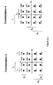
figure 2 shows four examples for signal constellations for a 16 QAM modulation scheme with Gray encoded bit symbols, -
figure 3 shows an exemplary signal constellation for 64-QAM Gray encoded bit symbols, -
figure 4 shows six exemplary signal constellations for 64-QAM Gray encoded bit symbols -
figure 5 is an exemplary embodiment of a communication system in which the method underlying the invention is employed, and -
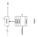
figure 6 explains details of the mapping unit shown infigure 5 . - For a better understanding of the embodiments, in the following the concept of a Log-Likelihood-Ratio (LLR) will be described as a metric for the bit reliabilities. First the straight forward calculation of the bit LLRs within the mapped symbols for a single transmission will be shown. Then the LLR calculation will be extended to the multiple transmission case.
- The mean LLR of the i-th bit bn i under the constraint that symbol sn has been transmitted for a transmission over a channel with additive white gaussian noise (AWGN) and equally likely symbols yields

where rn = sn denotes the mean received symbol under the constraint the symbol sn has been transmitted (AWGN case), dn,m 2 denotes the square of the Euclidean distance between the received symbol rn and the symbol sm , and Es /N 0 denotes the observed signal-to-noise ratio. - It can be seen from Equation (1) that the LLR depends on the signal-to-noise ratio Es /N 0 and the Euclidean distances dn,m between the signal constellation points.
- Considering multiple transmissions the mean LLR after the k-th transmission of the i-th bit bn i under the constraint that symbols s n (j) have been transmitted over independent AWGN channels and equally likely symbols yields

where j denotes the j-th transmission ((j-1)-th retransmission).Analogous to the single transmission case the mean LLRs depend on the signal-to-noise ratios and the Euclidean distances at each transmission time. - If no constellation rearrangement is performed the Euclidean distances d n,m (j) = d n,m (1) are constant for all transmissions and, hence, the bit reliabilities (LLRs) after k transmissions will be defined by the observed signal-to-noise ratio at each transmission time and the signal constellation points from the first transmission. For higher level modulation schemes (more than 2 bits per symbol) this results in varying mean LLRs for the bits, which in turn leads to different mean bit reliabilities. The differences in mean reliabilities remain over all retransmissions and lead to a degradation in decoder performance.
- In the following, the case of a 16-QAM system will be exemplarily considered resulting in 2 high reliable and 2 low reliable bits, where for the low reliable bits the reliability depends on transmitting a one or a zero (see
Figure 1 ). Hence, overall there exist 3 levels of reliabilities. - Level 1 (High Reliability, 2 bits): Bit mapping for ones (zeros) separated into the positive (negative) real half space for the i-bits and the imaginary half space the q-bits. Here, there is no difference whether the ones are mapped to the positive or to the negative half space.
- Level 2 (Low Reliability, 2 bits): Ones (zeros) are mapped to inner (outer) columns for the i-bits or to inner (outer) rows for the q-bits. Since there is a difference for the LLR depending on the mapping to the inner (outer) columns and rows,
Level 2 is further classified: - Level 2a: Mapping of in to inner columns and qn to inner rows respectively.
- Level 2b: Inverted mapping of Level 2a: Mapping of in to outer columns and qn to outer rows respectively.
- To ensure an optimal averaging process over the transmissions for all bits the levels of reliabilities have to be altered by changing the signal constellations according to the algorithms given in the following section.
- It has to be considered that the bit-mapping order is open prior initial transmission, but has to remain through retransmissions, e.g. bit-mapping for initial transmission: i1q1i2q2 ⇒ bit-mapping all retransmissions: i1q1i2q2.
- For the actual system implementation there are a number of possible signal constellations to achieve the averaging process over the retransmissions. Some examples for possible constellations are shown in
Figure 2 . The resulting bit reliabilities according toFigure 2 are given in Table 1.
- Moreover, Table 2 provides some examples how to combine the constellations for the
transmissions 1 to 4 (using 4 different mappings).Table 2. Examples for Constellation Rearrangement strategies for 16-QAM (using 4 mappings) with signal constellations according to Figure 2 and bit reliabilities according to Table 1. Transmission No. Scheme 1 (with Constellations) Scheme 2 (with Constellations) Scheme 3 (with Constellations) Scheme 4 (with Constellations) 1 1 1 1 1 2 2 2 3 3 3 3 4 2 4 4 4 3 4 2 - Two algorithms are given which describe schemes using 2 or 4 mappings overall. The approach using 2 mappings results in less system complexity, however has some performance degradation with respect to the approach using 4 mappings. The mapping for i- and q-bits can be done independently and, hence, in the following the mapping for the i-bits only is described. The algorithms for the q-bits work analog.
- Choose
Level 1 for i1 ⇒Level 2 for i2 - free choice if 2a or 2b - Choose
Level 1 for i2 ⇒Level 2 for i1 - free choice if 2a or 2b - Options:
- (a) Go to 1. Step and proceed with alternating between 1. and 2. Mapping
- (b)
Use 2. Mapping and proceed with using 2times 1. Mapping, 2times 2. Mapping and so on ... - Choose
Level 1 for i1 ⇒Level 2 for i2 - free choice if 2a or 2b - Choose
Level 1 for i2 ⇒Level 2 for i1 - free choice if 2a or 2b - Options:
- (a) Choose
Level 1 for i1 ⇒Level 2 for i2 with following options (a1) if in 1. Transmission 2a was used then use 2b (a2) if in 1. Transmission 2b was used then use 2a - (b) Choose
Level 1 for i2 ⇒Level 2 for i1 with following options (b1) if in 2. Transmission 2a was used then use 2b (b2) if in 2. Transmission 2b was used then use 2a - if option (a) in 3. Step
ChooseLevel 1 for i2 ⇒Level 2 for i1 with following options - (a1) if in 2. Transmission 2a was used then use 2b
- (a2) if in 2. Transmission 2b was used then use 2a
- (a1 ) if in 1. Transmission 2a was used then use 2b
- (a2) if in 1. Transmission 2b was used then use 2a
- Choose one out of 4 defined mappings
- Choose one out of 4 defined mappings except
- (a) the mapping used in 5. Step (previous transmission)
- (b) the
mapping giving Level 1 reliability to the same bit as in previous transmission - Choose one out of 2 remaining mappings not used in last 2 transmissions
- Choose mapping not used in last 3 transmissions
- Go to 5. Step
- In case of a 64-QAM system there will be 2 high reliable, 2 medium reliable and 2 low reliable bits, where for the low and medium reliable bits the reliability depends on transmitting a one or a zero (see
Figure 3 ). Hence, overall there exist 5 levels of reliabilities. - Level 1 (High Reliability, 2 bits): Bit mapping for ones (zeros) separated into the positive (negative) real half space for the i-bits and the imaginary half space for the q-bits. Here, there is no difference whether the ones are mapped to the positive or to the negative half space.
- Level 2 (Medium Reliability, 2 bits): Ones (zeros) are mapped to 4 inner and 2x2 outer columns for the i-bits or to 4 inner and 2x2 outer rows for the q-bits. Since there is a difference for the LLR depending on the mapping to the inner or outer column/
row Level 2 is further classified: - Level 2a: Mapping of in to 4 inner columns and qn to 4 inner rows respectively.
- Level 2b: Inverted mapping of 2a: in, to outer columns and qn to outer rows respectively
- Level 3 (Low Reliability, 2 bits): Ones (zeros) are mapped to columns 1-4-5-8/2-3-6-7 for the i-bits or to rows 1-4-5-8/2-3-6-7 for the q-bits. Since there is a difference for the LLR depending on the mapping to columns/rows 1-4-5-8 or 2-3-6-7
Level 3 is further classified: - Level 3a: Mapping of in to columns 2-3-6-7 and qn to rows 2-3-6-7 respectively
- Level 3b: Inverted mapping of 2a: in to columns 1-4-5-8 and qn to rows 1-4-5-8 respectively
- To ensure an optimal averaging process over the transmissions for all bits the levels of reliabilities have to be altered by changing the signal constellations according to the algorithms given in the following section.
- It has to be considered that the bit-mapping order is open prior initial transmission, but has to remain through retransmissions, e.g. bit-mapping for initial transmission: i1q1i2q2i3q3 ⇒ bit-mapping all retransmissions: i1q1i2q2 i3q3.
- Analog to 16-QAM for the actual system implementation there are a number of possible signal constellations to achieve the averaging process over the retransmissions. Some examples for possible constellations are shown in
Figure 4 . The resulting bit reliabilities according toFigure 4 are given in Table 3.
- Moreover, Table 4 provides some examples how to combine the constellations for the
transmissions 1 to 6 (using 6 different mappings).Table 4. Examples for Constellation Rearrangement strategies for 64-QAM (using 6 mappings) with signal constellations according to Figure 4 and bit reliabilities according to Table 3. Transmission No. Scheme 1 (with Constellations) Scheme 2 (with Constellations) Scheme 3 (with Constellations) Scheme 4 (with Constellations) 1 1 1 1 1 2 2 3 5 3 3 3 2 6 2 4 4 4 4 6 5 5 5 2 5 6 6 6 3 4 - Two algorithms are given which describe schemes using 3 or 6 mappings overall. The approach using 3 mappings results in less system complexity, however has some performance degradation with respect to the approach using 6 mappings.
- The mapping for i- and q-bits can be done independently and, hence, in the following the mapping for the i-bits only is described. The algorithms for the q-bits work analog.
- Choose
Level 1 for i1 - Choose
Level 2 for i2 (free choice if 2a or 2b)⇒ Level 3 for i3 - free choice if 3a or 3b - Options:
- (a) Choose
Level 1 for i2
ChooseLevel 2 for i3 (free choice if 2a or 2b)⇒ Level 3 for i1 - free choice if 3a or 3b - (b) Choose
Level 1 for i3
ChooseLevel 2 for i1 (free choice if 2a or 2b)⇒ Level 3 for i2 - free choice if 3a or 3b - if (a) in 2. Step
ChooseLevel 1 for i3
ChooseLevel 2 for i1 (free choice if 2a or 2b)⇒ Level 3 for i2 - free choice if 3a or 3b if (b) in 2. Step
ChooseLevel 1 for i2
ChooseLevel 2 for i3 (free choice if 2a or 2b)⇒ Level 3 for i1 - free choice if 3a or 3b - Choose one out of 3 defined mappings
- Choose one out of 3 defined mappings except the mapping used in previous transmission
- Choose one out of 3 defined mappings except the mapping used in last 2 transmissions
- Go to 4. Step
- Choose
Level 1 for i1 - Choose
Level 2 for i2 (free choice if 2a or 2b)⇒ Level 3 for i3 - free choice if 3a or 3b - Options:
- (a) Choose
Level 1 for i2
ChooseLevel 2 for i3 (free choice if 2a or 2b)⇒ Level 3 for i1 - free choice if 3a or 3b - (b) Choose
Level 1 for i3
ChooseLevel 2 for i1 (free choice if 2a or 2b)⇒ Level 3 for i2 - free choice if 3a or 3b - if (a) in 2. Step
ChooseLevel 1 for i3
ChooseLevel 2 for i1 (free choice if 2a or 2b)⇒ Level 3 for i2 - free choice if 3a or 3b
if (b) in 2. Step
ChooseLevel 1 for i2
ChooseLevel 2 for i3 (free choice if 2a or 2b)⇒ Level 3 for i1 - free choice if 3a or 3b - Choose
Level 1 for one bit out of i1, i2 or i3
ChooseLevel 2 for one out of two remaining bits with following restrictions - (a1) if in one of the previous transmission 2a was used for this bit then use 2b
- (a2) if in one of the previous transmission 2b was used for this bit then use
2a ⇒ Level 3 for remaining bit with following restrictions - (b1) if in one of the previous transmission 3a was used for this bit then use 3b
- (b2) if in one of the previous transmission 3b was used for this bit then use 3a
- Choose
Level 1 for one out of two bits not havingLevel 1 in 4. Step
ChooseLevel 2 for one out of two bits not havingLevel 2 in 4. Step with following restrictions - (a1) if in one of the previous transmission 2a was used for this bit then use 2b
- (a2) if in one of the previous transmission 2b was used for this bit then use
2a ⇒ Level 3 for remaining bit with following restrictions - (b1) if in one of the previous transmission 3a was used for this bit then use 3b
- (b2) if in one of the previous transmission 3b was used for this bit then use 3a
- Choose
Level 1 for bit not havingLevel 1 in 4. Step and 5. Step
ChooseLevel 2 for bit not havingLevel 2 in 4. Step and 5. Step with following restrictions - (a1) if in one of the previous transmission 2a was used for this bit then use 2b
- (a2) if in one of the previous transmission 2b was used for this bit then use
2a ⇒ Level 3 for remaining bit with following restrictions - (b1) if in one of the previous transmission 3a was used for this bit then use 3b
- (b2) if in one of the previous transmission 3b was used for this bit then use 3a
- Choose one out of 6 defined mappings
- Choose one out of 6 defined mappings except
- (a) the mapping used in 7. Step (previous transmission)
- (b) the
mapping giving Level 1 reliability to the same bit as in previous transmission - Choose one out of 6 defined mappings with giving
Level 1 reliability to the bit not havingLevel 1 in last 2 transmissions - Choose one out of 3 remaining mappings not used in last 3 transmissions
- Choose one out of 2 remaining mappings not used in last 4 transmissions
- Choose remaining mapping not used in last 5 transmissions
- Go to 7. Step
-
Figure 5 shows an exemplary embodiment of a communication system to which the present invention can be applied. More specifically, the communication system comprises atransmitter 10 and areceiver 20 which communicate through achannel 30 which can either be wire-bound or wireless, i.e. an air interface. From adata source 11, data packets are supplied to aFEC encoder 12, where redundancy bits are added to correct errors. The n bits output from the FEC decoder are subsequently supplied to amapping unit 13 acting as a modulator to output symbols formed according to the applied modulation scheme stored as a constellation pattern in a table 15. Upon transmission over thechannel 30, thereceiver 20 checks the received data packets, for example, by means of a cyclic redundancy check (CRC) for correctness. - If the received data packets are erroneous, the same are stored in a
temporary buffer 22 for subsequent soft combining with the retransmitted data packets. - A retransmission is launched by an automatic repeat request issued by an error detector (not shown) with the result that an identical data packet is transmitted from the
transmitter 10. In the combiningunit 21, the previously received erroneous data packets are soft-combined with the retransmitted data packets. The combiningunit 21 also acts as a demodulator and the same signal constellation pattern stored in the table 15 is used to demodulate the symbol which was used during the modulation of that symbol. - As illustrated in
figure 6 , the table 15 stores a plurality of signal constellation patterns which are selected for the individual (re)-transmissions according to a predetermined scheme. The scheme, i.e. the sequence of signal constellation patterns used for modulating/demodulating are either pre-stored in the transmitter and the receiver or are signaled by transmitter to the receiver prior to usage. - As mentioned before, the method underlying the invention rearranges the signal constellation patterns for the individual (re)-transmissions according to a predetermined scheme, such that the mean bit reliabilities are averaged out. Hence, the performance of the
FEC decoder 23 is significantly improved, resulting in a low bit error rate (BER) output from the decoder. - According to an illustrative embodiment of the hybrid ARQ retransmission method in a communication system, data packets being encoded with a forward error correction (FEC) technique prior to transmission are retransmitted based on an automatic repeat request and subsequently soft-combined with previously received erroneous data packets either on a symbol-by-symbol or a bit-by-bit basis, the symbols of said erroneous data packets being modulated employing a predetermined first signal constellation and the symbols of the retransmitted data packets being modulated employing at least a predetermined second signal constellation, each symbol bit having a mean bit reliability defined by the individual bit reliabilities over all symbols of the predetermined signal constellation characterized in that the predetermined first and the at least second signal constellation for the data packets are chosen such that the combined mean bit reliabilities for the respective bits of all transmissions are averaged out.
- According to the further embodiment of the retransmission method, the respective Euclidean distances between at least two modulated symbols of the first and respectively second signal constellation are different.
- According to the further embodiment of the retransmission method, the employed modulation scheme is Quadrature Amplitude Modulation (QAM), wherein more than two bits are mapped onto one symbol.
- According to the further embodiment of the retransmission method, the symbol bits of the data packets are Gray encoded.
- According to the further embodiment of the retransmission method, the employed modulation scheme is 16 DAM and that during modulation one of two levels of mean bit reliabilities are assigned to each of the four symbol bits.
- According to the further embodiment of the retransmission method, during modulation employing the first signal constellation, two bits of a symbol are assigned a high mean bit reliability and the two remaining bits of the symbol are assigned a low mean bit reliability and that during modulation employing the second signal constellation inverted mean bit reliabilities are assigned to the respective symbol bits.
- According to the further embodiment of the retransmission method, the employed modulation scheme is 64 CAM and that during modulation one of three levels of mean bit reliabilities are assigned to each of the six symbol bits.
- According to the further embodiment of the retransmission method, during modulation employing the fist signal constellation two bits of a symbol are as signed a high mean bit reliability, two further bits are assigned a medium mean bit reliability and two remaining bits of the symbol are assigned a low mean bit reliability and that during modulation employing the second signal constellation and a third signal constellation inverted mean bit reliabilities are assigned to respective symbol bits such that the sum of mean bit reliabilities for corresponding bits over all (re)-transmissions are near to equal.
- According to an illustrative embodiment of a receiver in a communication system embodied to carry out the method according to any of claims 1-8 further comprises table means to store the first and the at least second signal constellation pattern.
- According to the further embodiment of the receiver, the receiver further comprises storage means to store the sequence of signal constellations employed for modulating the symbol bits during all (re)-transmissions.
- According to an illustrative embodiment of a transmitter in a communication system the transmitter further comprises table means to store the first and the at least second signal constellation pattern.
- According to the further embodiment, the transmitter further comprises means to signal the sequence of signal constellations employed for modulating the symbol bits for all (re)-transmissions to the receiver.
Choose
Claims (7)
- A communication apparatus performing a hybrid automatic repeat request transmission, comprising:a encoding section that encodes data packets with a forward error correction hereinafter referred as FEC;a mapping section that maps the encoded data packets using one of a plurality of predetermined signal constellations to generate a symbol, each bit mapped onto the symbol having an individual bit reliability over all constellation points of the predetermined signal constellation;wherein the predetermined first and the second signal constellations for the data packets are selected such that the mean bit reliabilities for the respective bits mapped onto the symbol are averaged out through the retransmission.
- The communication apparatus according to claim 1, wherein the predetermined first and the second signal constellations for the data packets are selected such that the mean bit reliabilities for the respective bits mapped onto the symbol are averaged out through a combining with a first symbol modulated using a predetermined first signal constellation and a second symbol modulated using a predetermined second signal constellation.
- The communication apparatus according to claim 1 or 2, wherein the employed modulation scheme is Quadrature Amplitude Modulation hereinafter referred as QAM, wherein more than two bits are mapped onto one symbol.
- The communication apparatus according to one of claims 1-3, wherein the symbol bits of the data packets are Gray encoded.
- The communication apparatus according to one of claims 1-4, wherein the employed modulation scheme is 16 QAM and that during modulation one of two levels of mean bit reliabilities are assigned to each of the four symbol bits.
- The communication apparatus according to one of claims 1-4, wherein the employed modulation scheme is 64 QAM and that during modulation one of three levels of mean bit reliabilities are assigned to each of the six symbol bits.
- A hybrid ARQ transmission method in a communication apparatus, wherein data packets being encoded with a forward error correction hereinafter referred as FEC, are transmitted based on an automatic repeat request, a symbol of the data packets being modulated employing one of a plurality of predetermined signal constellations, each bit mapped onto the symbol having an individual bit reliability over all constellation points of the predetermined signal constellation, wherein the predetermined first and the second signal constellations for the data packets are selected such that the mean bit reliabilities for the respective bits mapped onto the symbol are averaged out through the retransmission.
Priority Applications (2)
| Application Number | Priority Date | Filing Date | Title |
|---|---|---|---|
| DK10178347.0T DK2259477T3 (en) | 2001-02-21 | 2001-02-21 | Hybrid ARQ method with signal constellation arrangement |
| EP10178347.0A EP2259477B1 (en) | 2001-02-21 | 2001-02-21 | Hybrid ARQ method with signal constellation rearrangement |
Applications Claiming Priority (4)
| Application Number | Priority Date | Filing Date | Title |
|---|---|---|---|
| EP10178347.0A EP2259477B1 (en) | 2001-02-21 | 2001-02-21 | Hybrid ARQ method with signal constellation rearrangement |
| EP04001471A EP1427128B9 (en) | 2001-02-21 | 2001-02-21 | Hybrid ARQ method with signal constellation rearrangement |
| EP06021982A EP1760928B1 (en) | 2001-02-21 | 2001-02-21 | Hybrid ARQ method with mapping rearrangement of the signals constellation |
| EP01923594A EP1293059B1 (en) | 2001-02-21 | 2001-02-21 | Hybrid arq method with signal constellation rearrangement |
Related Parent Applications (6)
| Application Number | Title | Priority Date | Filing Date |
|---|---|---|---|
| EP01923594A Division EP1293059B1 (en) | 2001-02-21 | 2001-02-21 | Hybrid arq method with signal constellation rearrangement |
| EP06021982A Division EP1760928B1 (en) | 2001-02-21 | 2001-02-21 | Hybrid ARQ method with mapping rearrangement of the signals constellation |
| EP01923594.4 Division | 2001-02-21 | ||
| EP04001471A Division EP1427128B9 (en) | 2001-02-21 | 2001-02-21 | Hybrid ARQ method with signal constellation rearrangement |
| EP04001471.4 Division | 2004-01-23 | ||
| EP06021982.1 Division | 2006-10-19 |
Publications (3)
| Publication Number | Publication Date |
|---|---|
| EP2259477A2 true EP2259477A2 (en) | 2010-12-08 |
| EP2259477A3 EP2259477A3 (en) | 2011-05-11 |
| EP2259477B1 EP2259477B1 (en) | 2017-07-19 |
Family
ID=37636065
Family Applications (2)
| Application Number | Title | Priority Date | Filing Date |
|---|---|---|---|
| EP10178347.0A Expired - Lifetime EP2259477B1 (en) | 2001-02-21 | 2001-02-21 | Hybrid ARQ method with signal constellation rearrangement |
| EP06021982A Expired - Lifetime EP1760928B1 (en) | 2001-02-21 | 2001-02-21 | Hybrid ARQ method with mapping rearrangement of the signals constellation |
Family Applications After (1)
| Application Number | Title | Priority Date | Filing Date |
|---|---|---|---|
| EP06021982A Expired - Lifetime EP1760928B1 (en) | 2001-02-21 | 2001-02-21 | Hybrid ARQ method with mapping rearrangement of the signals constellation |
Country Status (4)
| Country | Link |
|---|---|
| EP (2) | EP2259477B1 (en) |
| AT (1) | ATE532287T1 (en) |
| DK (1) | DK2259477T3 (en) |
| ES (1) | ES2373321T3 (en) |
Family Cites Families (2)
| Publication number | Priority date | Publication date | Assignee | Title |
|---|---|---|---|---|
| US6138260A (en) * | 1997-09-04 | 2000-10-24 | Conexant Systems, Inc. | Retransmission packet capture system within a wireless multiservice communications environment with turbo decoding |
| US6778558B2 (en) * | 1998-02-23 | 2004-08-17 | Lucent Technologies Inc. | System and method for incremental redundancy transmission in a communication system |
-
2001
- 2001-02-21 EP EP10178347.0A patent/EP2259477B1/en not_active Expired - Lifetime
- 2001-02-21 ES ES06021982T patent/ES2373321T3/en not_active Expired - Lifetime
- 2001-02-21 EP EP06021982A patent/EP1760928B1/en not_active Expired - Lifetime
- 2001-02-21 DK DK10178347.0T patent/DK2259477T3/en active
- 2001-02-21 AT AT06021982T patent/ATE532287T1/en active
Non-Patent Citations (5)
| Title |
|---|
| B.A. HARVEY; S. WICKER: "Packet Combining Systems based on the Viterbi Decoder", IEEE TRANSACTIONS ON COMMUNICATIONS, vol. 42, no. 2-4, April 1994 (1994-04-01) |
| D. CHASE: "Code combining: A maximum-likelihood decoding approach for combining an arbitrary number of noisy packets", IEEE TRANS. COMMUN., vol. COM-33, May 1985 (1985-05-01), pages 385 - 393, XP000758537, DOI: doi:10.1109/TCOM.1985.1096314 |
| M.P. SCHMITT: "Hybrid ARQ Scheme employing TCM and Packet Combining", ELECTRONICS LETTERS, vol. 34, no. 18, September 1998 (1998-09-01), XP006010263, DOI: doi:10.1049/el:19981232 |
| S. KALLEL: "Analysis of a type II hybrid ARQ scheme with code combining", IEEE TRANSACTIONS ON COMMUNICATIONS, vol. 38, no. 8, August 1990 (1990-08-01), XP002000135, DOI: doi:10.1109/26.58745 |
| S. KALLEL; R. LINK; S. BAKHTIYARI: "Throughput performance of Memory ARQ schemes", IEEE TRANSACTIONS ON VEHICULAR TECHNOLOGY, vol. 48, no. 3, May 1999 (1999-05-01), XP000906444, DOI: doi:10.1109/25.765006 |
Also Published As
| Publication number | Publication date |
|---|---|
| DK2259477T3 (en) | 2017-10-23 |
| EP1760928A3 (en) | 2009-03-04 |
| ES2373321T3 (en) | 2012-02-02 |
| EP2259477A3 (en) | 2011-05-11 |
| EP2259477B1 (en) | 2017-07-19 |
| EP1760928B1 (en) | 2011-11-02 |
| EP1760928A2 (en) | 2007-03-07 |
| ATE532287T1 (en) | 2011-11-15 |
Similar Documents
| Publication | Publication Date | Title |
|---|---|---|
| US6892341B2 (en) | Data transmission apparatus using a constellation rearrangement | |
| EP1830510B1 (en) | Hybrid ARQ method for packet data transmission | |
| EP1313250B1 (en) | Hybrid ARQ apparatus for packet data transmission | |
| US7697565B2 (en) | Data transmission apparatus and communication system using a constellation rearrangement | |
| EP1427128B9 (en) | Hybrid ARQ method with signal constellation rearrangement | |
| EP1760928B1 (en) | Hybrid ARQ method with mapping rearrangement of the signals constellation | |
| CA2488267C (en) | Hybrid arq method with signal constellation rearrangement | |
| HK1066949B (en) | Hybrid arq method with signal constellation rearrangement | |
| HK1054138B (en) | Hybrid arq method for packet data transmission | |
| HK1056060B (en) | Hybrid arq method for packet data transmission |
Legal Events
| Date | Code | Title | Description |
|---|---|---|---|
| PUAI | Public reference made under article 153(3) epc to a published international application that has entered the european phase |
Free format text: ORIGINAL CODE: 0009012 |
|
| AC | Divisional application: reference to earlier application |
Ref document number: 1427128 Country of ref document: EP Kind code of ref document: P Ref document number: 1293059 Country of ref document: EP Kind code of ref document: P Ref document number: 1760928 Country of ref document: EP Kind code of ref document: P |
|
| AK | Designated contracting states |
Kind code of ref document: A2 Designated state(s): AT BE CH CY DE DK ES FI FR GB GR IE IT LI LU MC NL PT SE TR |
|
| PUAL | Search report despatched |
Free format text: ORIGINAL CODE: 0009013 |
|
| AK | Designated contracting states |
Kind code of ref document: A3 Designated state(s): AT BE CH CY DE DK ES FI FR GB GR IE IT LI LU MC NL PT SE TR |
|
| 17P | Request for examination filed |
Effective date: 20110929 |
|
| 17Q | First examination report despatched |
Effective date: 20140312 |
|
| RAP1 | Party data changed (applicant data changed or rights of an application transferred) |
Owner name: PANASONIC INTELLECTUAL PROPERTY CORPORATION OF AME |
|
| REG | Reference to a national code |
Ref country code: DE Ref legal event code: R079 Ref document number: 60150521 Country of ref document: DE Free format text: PREVIOUS MAIN CLASS: H04L0001180000 Ipc: H04L0001000000 |
|
| GRAP | Despatch of communication of intention to grant a patent |
Free format text: ORIGINAL CODE: EPIDOSNIGR1 |
|
| STAA | Information on the status of an ep patent application or granted ep patent |
Free format text: STATUS: GRANT OF PATENT IS INTENDED |
|
| RIC1 | Information provided on ipc code assigned before grant |
Ipc: H04L 1/18 20060101ALI20170309BHEP Ipc: H04L 1/00 20060101AFI20170309BHEP Ipc: H04L 27/34 20060101ALI20170309BHEP |
|
| INTG | Intention to grant announced |
Effective date: 20170324 |
|
| RIN1 | Information on inventor provided before grant (corrected) |
Inventor name: WENGERTER, CHRISTIAN Inventor name: GOLITSCHEK EDLER VON ELBWART, ALEXANDER Inventor name: SCHMITT, MICHAEL PHILIPP Inventor name: SEIDEL, EIKO |
|
| GRAS | Grant fee paid |
Free format text: ORIGINAL CODE: EPIDOSNIGR3 |
|
| GRAA | (expected) grant |
Free format text: ORIGINAL CODE: 0009210 |
|
| STAA | Information on the status of an ep patent application or granted ep patent |
Free format text: STATUS: THE PATENT HAS BEEN GRANTED |
|
| AC | Divisional application: reference to earlier application |
Ref document number: 1760928 Country of ref document: EP Kind code of ref document: P Ref document number: 1293059 Country of ref document: EP Kind code of ref document: P Ref document number: 1427128 Country of ref document: EP Kind code of ref document: P |
|
| AK | Designated contracting states |
Kind code of ref document: B1 Designated state(s): AT BE CH CY DE DK ES FI FR GB GR IE IT LI LU MC NL PT SE TR |
|
| REG | Reference to a national code |
Ref country code: GB Ref legal event code: FG4D |
|
| REG | Reference to a national code |
Ref country code: CH Ref legal event code: EP |
|
| REG | Reference to a national code |
Ref country code: IE Ref legal event code: FG4D |
|
| REG | Reference to a national code |
Ref country code: AT Ref legal event code: REF Ref document number: 911345 Country of ref document: AT Kind code of ref document: T Effective date: 20170815 |
|
| REG | Reference to a national code |
Ref country code: DE Ref legal event code: R096 Ref document number: 60150521 Country of ref document: DE |
|
| REG | Reference to a national code |
Ref country code: NL Ref legal event code: FP |
|
| REG | Reference to a national code |
Ref country code: SE Ref legal event code: TRGR |
|
| REG | Reference to a national code |
Ref country code: DK Ref legal event code: T3 Effective date: 20171018 |
|
| REG | Reference to a national code |
Ref country code: ES Ref legal event code: FG2A Ref document number: 2644213 Country of ref document: ES Kind code of ref document: T3 Effective date: 20171128 |
|
| REG | Reference to a national code |
Ref country code: AT Ref legal event code: MK05 Ref document number: 911345 Country of ref document: AT Kind code of ref document: T Effective date: 20170719 |
|
| PG25 | Lapsed in a contracting state [announced via postgrant information from national office to epo] |
Ref country code: AT Free format text: LAPSE BECAUSE OF FAILURE TO SUBMIT A TRANSLATION OF THE DESCRIPTION OR TO PAY THE FEE WITHIN THE PRESCRIBED TIME-LIMIT Effective date: 20170719 |
|
| REG | Reference to a national code |
Ref country code: FR Ref legal event code: PLFP Year of fee payment: 18 |
|
| PG25 | Lapsed in a contracting state [announced via postgrant information from national office to epo] |
Ref country code: GR Free format text: LAPSE BECAUSE OF FAILURE TO SUBMIT A TRANSLATION OF THE DESCRIPTION OR TO PAY THE FEE WITHIN THE PRESCRIBED TIME-LIMIT Effective date: 20171020 |
|
| REG | Reference to a national code |
Ref country code: DE Ref legal event code: R097 Ref document number: 60150521 Country of ref document: DE |
|
| PLBE | No opposition filed within time limit |
Free format text: ORIGINAL CODE: 0009261 |
|
| STAA | Information on the status of an ep patent application or granted ep patent |
Free format text: STATUS: NO OPPOSITION FILED WITHIN TIME LIMIT |
|
| 26N | No opposition filed |
Effective date: 20180420 |
|
| REG | Reference to a national code |
Ref country code: CH Ref legal event code: PL |
|
| PG25 | Lapsed in a contracting state [announced via postgrant information from national office to epo] |
Ref country code: MC Free format text: LAPSE BECAUSE OF FAILURE TO SUBMIT A TRANSLATION OF THE DESCRIPTION OR TO PAY THE FEE WITHIN THE PRESCRIBED TIME-LIMIT Effective date: 20170719 |
|
| REG | Reference to a national code |
Ref country code: IE Ref legal event code: MM4A |
|
| REG | Reference to a national code |
Ref country code: BE Ref legal event code: MM Effective date: 20180228 |
|
| PG25 | Lapsed in a contracting state [announced via postgrant information from national office to epo] |
Ref country code: LU Free format text: LAPSE BECAUSE OF NON-PAYMENT OF DUE FEES Effective date: 20180221 Ref country code: CH Free format text: LAPSE BECAUSE OF NON-PAYMENT OF DUE FEES Effective date: 20180228 Ref country code: LI Free format text: LAPSE BECAUSE OF NON-PAYMENT OF DUE FEES Effective date: 20180228 |
|
| PG25 | Lapsed in a contracting state [announced via postgrant information from national office to epo] |
Ref country code: IE Free format text: LAPSE BECAUSE OF NON-PAYMENT OF DUE FEES Effective date: 20180221 |
|
| PG25 | Lapsed in a contracting state [announced via postgrant information from national office to epo] |
Ref country code: BE Free format text: LAPSE BECAUSE OF NON-PAYMENT OF DUE FEES Effective date: 20180228 |
|
| PG25 | Lapsed in a contracting state [announced via postgrant information from national office to epo] |
Ref country code: TR Free format text: LAPSE BECAUSE OF FAILURE TO SUBMIT A TRANSLATION OF THE DESCRIPTION OR TO PAY THE FEE WITHIN THE PRESCRIBED TIME-LIMIT Effective date: 20170719 |
|
| PGFP | Annual fee paid to national office [announced via postgrant information from national office to epo] |
Ref country code: NL Payment date: 20200219 Year of fee payment: 20 Ref country code: DK Payment date: 20200224 Year of fee payment: 20 Ref country code: DE Payment date: 20200219 Year of fee payment: 20 Ref country code: FI Payment date: 20200220 Year of fee payment: 20 Ref country code: SE Payment date: 20200220 Year of fee payment: 20 Ref country code: ES Payment date: 20200322 Year of fee payment: 20 Ref country code: GB Payment date: 20200219 Year of fee payment: 20 Ref country code: IT Payment date: 20200225 Year of fee payment: 20 |
|
| PG25 | Lapsed in a contracting state [announced via postgrant information from national office to epo] |
Ref country code: PT Free format text: LAPSE BECAUSE OF FAILURE TO SUBMIT A TRANSLATION OF THE DESCRIPTION OR TO PAY THE FEE WITHIN THE PRESCRIBED TIME-LIMIT Effective date: 20170719 |
|
| PG25 | Lapsed in a contracting state [announced via postgrant information from national office to epo] |
Ref country code: CY Free format text: LAPSE BECAUSE OF FAILURE TO SUBMIT A TRANSLATION OF THE DESCRIPTION OR TO PAY THE FEE WITHIN THE PRESCRIBED TIME-LIMIT Effective date: 20170719 |
|
| PGFP | Annual fee paid to national office [announced via postgrant information from national office to epo] |
Ref country code: FR Payment date: 20200219 Year of fee payment: 20 |
|
| REG | Reference to a national code |
Ref country code: DE Ref legal event code: R071 Ref document number: 60150521 Country of ref document: DE |
|
| REG | Reference to a national code |
Ref country code: DK Ref legal event code: EUP Expiry date: 20210221 |
|
| REG | Reference to a national code |
Ref country code: NL Ref legal event code: MK Effective date: 20210220 |
|
| REG | Reference to a national code |
Ref country code: GB Ref legal event code: PE20 Expiry date: 20210220 |
|
| REG | Reference to a national code |
Ref country code: FI Ref legal event code: MAE |
|
| REG | Reference to a national code |
Ref country code: SE Ref legal event code: EUG |
|
| PG25 | Lapsed in a contracting state [announced via postgrant information from national office to epo] |
Ref country code: GB Free format text: LAPSE BECAUSE OF EXPIRATION OF PROTECTION Effective date: 20210220 |
|
| REG | Reference to a national code |
Ref country code: ES Ref legal event code: FD2A Effective date: 20220128 |
|
| PG25 | Lapsed in a contracting state [announced via postgrant information from national office to epo] |
Ref country code: ES Free format text: LAPSE BECAUSE OF EXPIRATION OF PROTECTION Effective date: 20210222 |