EP2258920A2 - Packer providing multiple seals and having swellable element isolatable from the wellbore - Google Patents
Packer providing multiple seals and having swellable element isolatable from the wellbore Download PDFInfo
- Publication number
- EP2258920A2 EP2258920A2 EP10003636A EP10003636A EP2258920A2 EP 2258920 A2 EP2258920 A2 EP 2258920A2 EP 10003636 A EP10003636 A EP 10003636A EP 10003636 A EP10003636 A EP 10003636A EP 2258920 A2 EP2258920 A2 EP 2258920A2
- Authority
- EP
- European Patent Office
- Prior art keywords
- mandrel
- packer
- swellable
- bias unit
- tool
- Prior art date
- Legal status (The legal status is an assumption and is not a legal conclusion. Google has not performed a legal analysis and makes no representation as to the accuracy of the status listed.)
- Withdrawn
Links
- 239000012530 fluid Substances 0.000 claims abstract description 61
- 230000003213 activating effect Effects 0.000 claims abstract description 23
- 230000008961 swelling Effects 0.000 claims abstract description 15
- 238000002955 isolation Methods 0.000 claims description 53
- 239000003795 chemical substances by application Substances 0.000 claims description 24
- 230000007246 mechanism Effects 0.000 claims description 6
- XLYOFNOQVPJJNP-UHFFFAOYSA-N water Substances O XLYOFNOQVPJJNP-UHFFFAOYSA-N 0.000 claims description 6
- 238000004519 manufacturing process Methods 0.000 claims description 4
- 238000005553 drilling Methods 0.000 claims description 2
- 239000013536 elastomeric material Substances 0.000 claims description 2
- 238000000034 method Methods 0.000 claims 4
- 238000012856 packing Methods 0.000 claims 1
- 238000005086 pumping Methods 0.000 claims 1
- 230000000593 degrading effect Effects 0.000 abstract 1
- 239000000463 material Substances 0.000 description 14
- 238000004873 anchoring Methods 0.000 description 12
- 241000282472 Canis lupus familiaris Species 0.000 description 11
- 229920001971 elastomer Polymers 0.000 description 6
- 230000014759 maintenance of location Effects 0.000 description 6
- 238000007789 sealing Methods 0.000 description 6
- 239000003921 oil Substances 0.000 description 5
- 239000002184 metal Substances 0.000 description 4
- 230000006835 compression Effects 0.000 description 3
- 238000007906 compression Methods 0.000 description 3
- 239000000806 elastomer Substances 0.000 description 3
- 238000001125 extrusion Methods 0.000 description 3
- 239000005060 rubber Substances 0.000 description 3
- 229920002449 FKM Polymers 0.000 description 2
- 229920006172 Tetrafluoroethylene propylene Polymers 0.000 description 2
- 230000004913 activation Effects 0.000 description 2
- 230000007423 decrease Effects 0.000 description 2
- 239000007788 liquid Substances 0.000 description 2
- 244000043261 Hevea brasiliensis Species 0.000 description 1
- 229920000459 Nitrile rubber Polymers 0.000 description 1
- 229920006169 Perfluoroelastomer Polymers 0.000 description 1
- 230000004075 alteration Effects 0.000 description 1
- 230000008901 benefit Effects 0.000 description 1
- 238000011109 contamination Methods 0.000 description 1
- 238000007796 conventional method Methods 0.000 description 1
- 229920001577 copolymer Polymers 0.000 description 1
- 230000009977 dual effect Effects 0.000 description 1
- 230000000694 effects Effects 0.000 description 1
- 230000007613 environmental effect Effects 0.000 description 1
- HQQADJVZYDDRJT-UHFFFAOYSA-N ethene;prop-1-ene Chemical group C=C.CC=C HQQADJVZYDDRJT-UHFFFAOYSA-N 0.000 description 1
- -1 ethylene propylene diene Chemical class 0.000 description 1
- 229920001973 fluoroelastomer Polymers 0.000 description 1
- 229920002313 fluoropolymer Polymers 0.000 description 1
- 239000004811 fluoropolymer Substances 0.000 description 1
- 229920006168 hydrated nitrile rubber Polymers 0.000 description 1
- 239000010720 hydraulic oil Substances 0.000 description 1
- 238000007373 indentation Methods 0.000 description 1
- 229910052500 inorganic mineral Inorganic materials 0.000 description 1
- 230000001788 irregular Effects 0.000 description 1
- 229920003049 isoprene rubber Polymers 0.000 description 1
- 239000011707 mineral Substances 0.000 description 1
- 238000012986 modification Methods 0.000 description 1
- 230000004048 modification Effects 0.000 description 1
- 239000000178 monomer Substances 0.000 description 1
- 229920003052 natural elastomer Polymers 0.000 description 1
- 229920001194 natural rubber Polymers 0.000 description 1
- 150000002825 nitriles Chemical class 0.000 description 1
- 229920003023 plastic Polymers 0.000 description 1
- 239000004033 plastic Substances 0.000 description 1
- 229920001084 poly(chloroprene) Polymers 0.000 description 1
- 229920001200 poly(ethylene-vinyl acetate) Polymers 0.000 description 1
- 229920000636 poly(norbornene) polymer Polymers 0.000 description 1
- 239000012779 reinforcing material Substances 0.000 description 1
- 230000000717 retained effect Effects 0.000 description 1
- 229920003048 styrene butadiene rubber Polymers 0.000 description 1
Images




Classifications
-
- E—FIXED CONSTRUCTIONS
- E21—EARTH OR ROCK DRILLING; MINING
- E21B—EARTH OR ROCK DRILLING; OBTAINING OIL, GAS, WATER, SOLUBLE OR MELTABLE MATERIALS OR A SLURRY OF MINERALS FROM WELLS
- E21B33/00—Sealing or packing boreholes or wells
- E21B33/10—Sealing or packing boreholes or wells in the borehole
- E21B33/12—Packers; Plugs
- E21B33/1208—Packers; Plugs characterised by the construction of the sealing or packing means
-
- E—FIXED CONSTRUCTIONS
- E21—EARTH OR ROCK DRILLING; MINING
- E21B—EARTH OR ROCK DRILLING; OBTAINING OIL, GAS, WATER, SOLUBLE OR MELTABLE MATERIALS OR A SLURRY OF MINERALS FROM WELLS
- E21B23/00—Apparatus for displacing, setting, locking, releasing or removing tools, packers or the like in boreholes or wells
- E21B23/06—Apparatus for displacing, setting, locking, releasing or removing tools, packers or the like in boreholes or wells for setting packers
-
- E—FIXED CONSTRUCTIONS
- E21—EARTH OR ROCK DRILLING; MINING
- E21B—EARTH OR ROCK DRILLING; OBTAINING OIL, GAS, WATER, SOLUBLE OR MELTABLE MATERIALS OR A SLURRY OF MINERALS FROM WELLS
- E21B33/00—Sealing or packing boreholes or wells
- E21B33/10—Sealing or packing boreholes or wells in the borehole
- E21B33/12—Packers; Plugs
- E21B33/1208—Packers; Plugs characterised by the construction of the sealing or packing means
- E21B33/1216—Anti-extrusion means, e.g. means to prevent cold flow of rubber packing
-
- E—FIXED CONSTRUCTIONS
- E21—EARTH OR ROCK DRILLING; MINING
- E21B—EARTH OR ROCK DRILLING; OBTAINING OIL, GAS, WATER, SOLUBLE OR MELTABLE MATERIALS OR A SLURRY OF MINERALS FROM WELLS
- E21B33/00—Sealing or packing boreholes or wells
- E21B33/10—Sealing or packing boreholes or wells in the borehole
- E21B33/12—Packers; Plugs
- E21B33/126—Packers; Plugs with fluid-pressure-operated elastic cup or skirt
-
- E—FIXED CONSTRUCTIONS
- E21—EARTH OR ROCK DRILLING; MINING
- E21B—EARTH OR ROCK DRILLING; OBTAINING OIL, GAS, WATER, SOLUBLE OR MELTABLE MATERIALS OR A SLURRY OF MINERALS FROM WELLS
- E21B33/00—Sealing or packing boreholes or wells
- E21B33/10—Sealing or packing boreholes or wells in the borehole
- E21B33/12—Packers; Plugs
- E21B33/127—Packers; Plugs with inflatable sleeve
- E21B33/1277—Packers; Plugs with inflatable sleeve characterised by the construction or fixation of the sleeve
-
- E—FIXED CONSTRUCTIONS
- E21—EARTH OR ROCK DRILLING; MINING
- E21B—EARTH OR ROCK DRILLING; OBTAINING OIL, GAS, WATER, SOLUBLE OR MELTABLE MATERIALS OR A SLURRY OF MINERALS FROM WELLS
- E21B33/00—Sealing or packing boreholes or wells
- E21B33/10—Sealing or packing boreholes or wells in the borehole
- E21B33/12—Packers; Plugs
- E21B33/128—Packers; Plugs with a member expanded radially by axial pressure
Definitions
- Operators use packers downhole to isolate portions of a wellbore's annulus when performing various operations. For example, operators can selectively frac multiple isolated zones by deploying a tool string having one or more packers into an open or cased wellbore. When activated, the packers isolate the wellbore's annulus so the isolated zones can be separately treated.
- One conventional packer uses a compression-set element that expands radially outward to the borehole wall when subjected to compression. Being compression-set, the element's length is limited by practical limitations because a longer compression-set element would experience undesirable buckling and collapsing during use. However, a shorter compression-set element may not adequately seal against irregularities of the surrounding borehole wall. Moreover, this type of packer typically needs a sophisticated mechanism to actuate the compression-set element.
- Another conventional packer uses an inflatable element. When deployed, a differential pressure is introduced to inflate the element so that it produces a seal with the surrounding borehole wall. Compared to a compression-set packer, however, the inflatable packer can be significantly more costly and can be more difficult to implement and deploy.
- Another conventional packer uses a swellable element. When run into position downhole, fluid enlarges the swellable element until it produces a seal with the borehole wall. This can take up to several days to complete in some implementations. Once swollen, the element's material can begin to degrade during its continued exposure to the fluid, and a high differential pressure or an absence of the activating fluid that swelled the element can compromise the swellable element's seal.
- the swellable element may become extruded if it is allowed to swell in an uncontrolled manner.
- metal rings can anchor the top and bottom of the swellable element and prevent it from expanding axially beyond the anchoring points. Examples of such metal rings are used by TAM International and Swelltec. Backup rings may also be used in addition to the metal anchoring rings at either end, as done by Easywell, for example.
- the subject matter of the present disclosure is directed to overcoming, or at least reducing the effects of, one or more of the problems set forth above.
- a downhole tool such as a packer provides multiple seals when deployed downhole.
- an activating agent e.g ., oil, water, etc.
- a swellable packer element on the tool's mandrel swells. Because the swelling may take several days to seal the downhole annulus, the tool has one or more isolation elements disposed adjacent the swellable element to at least partially isolate the downhole annulus.
- the swellable packer element is exposed to the activating agent so it can begin to swell. As the swellable element swells, the one or more isolation elements are activated to at least partially isolate the downhole annulus.
- the isolation elements can produce one or more secondary seals (either full or partial) with the surrounding borehole wall to prevent fluid flow through the downhole annulus while the swellable element swells.
- the isolation elements can keep the swellable element from becoming overly extruded as it swells by limiting the axial expansion of the swellable element along the tool's mandrel.
- the isolation elements can at least partially isolate the swellable element from the downhole annulus and thereby limit the swellable elements exposure to downhole fluids that may tend to degrade the element over time.
- the one or more isolation elements are disposed on the tool's mandrel adjacent the swellable packer element and are at least partially deformable radially outward to the surrounding borehole wall to produce the isolation discussed above.
- one or more cup packers are biased to deform radially outward and are oriented to restrict fluid flow through the downhole annulus in one or more directions. These one or more cup packers may be biased to deform radially outward by their natural configuration, by fluid pressure in the downhole annulus acting on the cup packer, or by a bias unit configured to deform the cup packer.
- a compressible packer is disposed on the mandrel adjacent the swellable element, and a bias unit is releasably affixed on the mandrel adjacent the compressible packer.
- the bias unit is releasable on the mandrel and is axially biasable toward the compressible packer to at least partially deform the compressible packer radially outward to the surrounding borehole wall.
- the bias unit can be released in a number of ways.
- the swellable element can release the bias unit to compress the compressible packer.
- axial swelling of the swellable element can break the bias unit's temporary connection to the mandrel. This temporary connection can use shear pins and dogs to releasably affix the bias unit on the mandrel.
- the bias units can then compress against the compressible packer to deform the packer.
- fluid pressure communicated through the mandrel can release the bias unit to compress the compressible packer.
- fluid pressure from the mandrel's bore can enter a port and fill a chamber of the bias unit. The fluid pressure filling this chamber can then break the bias unit's temporary connection to the mandrel and can bias the unit axially toward the compressible packer to compress it.
- FIG. 1 illustrates a tubing string deployed downhole and having a tool with a swellable packer element capable of being isolated from the wellbore.
- FIG. 2 illustrates a partial cross-sectional of a packer according to certain teachings of the present disclosure.
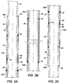
- FIGS. 3A-3C illustrate detailed cross-sections of the packer in FIG. 2 .
- FIGS. 4A-4C show portion of the packer in FIG. 2 during various stages of deployment.
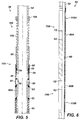
- FIG. 5 illustrates portion of another packer according to certain teachings of the present disclosure that is activated by fluid pressure and that has an alternate bias unit.
- FIG. 6 illustrates a partial cross-section of yet another packer according to certain teachings of the present disclosure that is activated by fluid pressure and that has another bias unit.
- FIGS. 7A-7C show portion of the packer in FIG. 6 during various stages of deployment.
- FIG. 8 shows a packer according to certain teachings of the present disclosure having a different symmetrical arrangement.
- FIG. 9 shows a packer according to certain teachings of the present disclosure having an asymmetrical arrangement.
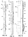
- FIG. 10 illustrates a packer according to certain teachings of the present disclosure having alternate deformable elements flanking a swellable element.
- FIG. 11 illustrates the packer of FIG. 10 with an inverted arrangement.
- FIG. 12 illustrates portion of a packer according to certain teachings of the present disclosure having a cup packer deformable by a bias unit.
- a tool 50 in FIG. 1 deploys downhole within a borehole 10 with a tubing string 22 extending from a rig 20 or the like.
- the tool 50 can be a packer used to isolate the downhole annulus 12 for various operations, such as treating separate zones in a frac operation.
- the downhole tool 50 can be a liner hanger, a wireline lock, a bridge plug, or other tool that uses an energized annular seal to seal the downhole annulus 12.
- the borehole 10 may have a uniform or irregular wall surface and may be an open hole, a casing, or any downhole tubular.
- the packer 50 has one or more swellable packer elements 60 disposed on a mandrel 52 and has one or more isolation elements 70 disposed on the mandrel 52 adjacent the swellable elements 60. As shown particularly in FIG. 1 , the packer 50 has one swellable element 60 and has two isolation elements 70A-B flanking the ends of the swellable element 60.
- an activating agent such as water, oil, production fluid, etc., engorges the swellable element 60, expanding it from an initial hardness of about 60 Durometer to a final hardness of about 20-30 Durometer, for example.
- the swellable element 60 fills the downhole annulus 12 to produce a fluid seal.
- each of the isolation element 70A-B has one or more deformable elements. When deploying the tool 10 downhole, these one or more deformable elements of the isolation elements 70A-B are at least partially deformed radially outward to the surrounding borehole wall so the elements 70A-B can at least partially isolate the downhole annulus 12.
- the isolation from the elements 70A-B can reduce or prevent issues with fluid passing through the downhole annulus 12 while the swellable element 60 swells.
- the isolation can prevent the swellable element 60 from over exposure to wellbore fluids in the annulus 12 (including the activating agent) that could degrade the element's material.
- the isolation elements 70A-B can also limit the possible extrusion of the swellable element 60 as its swells.
- FIG. 2 One arrangement of a packer 50 is shown in FIG. 2 .
- the packer 50 has a symmetrical arrangement with a swellable packer element 60 flanked at each end by isolation elements 70A-B as described previously.
- the swellable element 60 is a swellable sleeve of material that can swell in the presence of an activation agent, such as water, oil, production fluid, etc.
- the isolation elements 70A-B include compressible packers 80 that deform when compressed.
- these elements 60/70A-B are capable of forming different seals with the surrounding borehole wall.
- the compressible packers 80AB can provide a compressed form of seal particularly suited for sealing against uniform surfaces and for maintaining a high pressure differential.
- the swellable element 60 can provide an engorged or swollen form of seal. Although this swollen seal may be weaker than the compressed seal, the swollen seal can extend along a greater expanse of the borehole and may actually provide a better seal against less uniform surfaces downhole than can be achieved with the compressed seal.
- the swellable element 60 positions onto the outside of the mandrel 52 and can be bonded thereto using conventional techniques.
- the compressible packers 80A-B mount on the mandrel 52 at each end of the swellable element 60 and are capable of moving axially on the mandrel 52.
- Back-up rings 62 can be used between the adjoining ends of the swellable element 60 and packers 80A-B.
- additional back-up rings 82 can also position at the ends of the compressible packers 80A-B.
- the isolation elements 70A-B (shown in FIGS. 3A & 3C ) have sliding sleeves 85A-B movably mounted on the mandrel 52.
- Each sleeve 85A-B has a proximal end engaging one of the packers 80A-B (via a back-up ring 82) and has a distal end engaging a bias or pressure unit 90A-B.
- the bias units 90A-B are modular so that each bias unit 90A-B has a barrel 92 that threads onto an anchoring sleeve 95.
- the anchoring sleeves 95 couple to the sliding sleeves 85 by shear pins 88, although other temporary connections could be used.
- the anchoring sleeves 85 also have slots for dogs 56 that fit into a groove 54 in the mandrel 52. When engaged in this groove 54, the dogs 56 releasably affix or retain the bias units 90A-B in place on the mandrel 52 as an additional form of temporary connection on the packer 50.
- Each barrel 92 encloses a variable chamber 94 around the mandrel 52 that contains atmospheric pressure or other low pressure level sealed therein by seals 96/98.
- a lip on the end of the barrel 92 has an outer sealing ring 96 that engages the outside of the mandrel 52.
- an inner sealing ring 98 disposed on the outside of the mandrel 52 engages an inside of the barrel 92 to enclose the chamber 94, although other forms of sealing could be used.
- the packer 50 is deployed and used downhole.
- the packer 50 is initially deployed with the swelleable element 60 unexpanded.
- the sliding sleeve 85 is affixed to the anchoring sleeve 95 with the shear pins 88, and the bias unit's sleeve 95 and barrel 92 are held in place on the mandrel 52 by the dogs 56 engaged in the mandrel's groove 54. (Although not shown, the opposite portion of the packer 50 is similarly arranged.)
- the chamber 94 has atmospheric pressure or some other low pressure level when assembled at the surface.
- the high pressure environment of pumped or existing fluids in the annulus tends to compress this chamber 94 and force the barrel 92 and attached sleeve 95 axially on the mandrel 52 towards the compressible packer 80A.
- the barrel 92 initially remains fixed on the mandrel 52, being retained by the dogs 56 engaged in the mandrel's groove 54.
- a pumped or existing activating agent in the downhole annulus interacts with the swellable element 60, causing it to expand both axially and radially
- operators may use a mud system 30 as depicted in Fig. 1 to pump the activating agent downhole via the drill string 22, and the agent may enter the annulus via a bottom hole assembly, a sliding sleeve, or the like).
- the swellable element's radial expansion can eventually seal the element 60 against the surrounding borehole wall, although this can take several days to complete.
- the swellable element 60 may produce about 100 to 200-psi of force so that the breakable connection provided by the shear pins 88 or other temporary connection would need to be configured accordingly.
- an inner groove 86 on the inside of the shifted sliding sleeve 85 eventually meets the dogs 56, giving the dogs 56 the freedom to disengage from the mandrel's groove 54.
- the anchoring sleeve 85 is released from the mandrel 52 and is free to move axially on the mandrel 52.
- external pressure exerted on the released barrel 92 moves it axially along the mandrel 52 toward the swellable element 60 because the lower pressure in the chamber 94 attempts to decrease in volume relative to the higher surrounding pressure in the wellbore annulus.
- the shifting barrel 92 pushes the sleeves 85/95 axially toward the swellable element 60, and the shifting sleeve 85 pushes against the compressible packer 80A.
- the swellable element 60 pushes against the packer 80A from the other side as it continues to swell axially. This compression deforms the packer 80A outward to engage the surrounding borehole wall to at least partially isolate the swellable element 60 from the downhole annulus or to form a secondary seal with the borehole wall.
- the chamber 94 can have atmospheric pressure therein, the chamber 94 will move the barrel 92 as long as the packer 50 is run to a minimum depth for downhole pressure to actuate the barrel 92. Therefore, the pressure in the chamber 94 can be set for a particular implementation.
- Using the chambers 94 to energize the compressible packer 80A instead of - relying on the force generated by the swellable element 60 means that the force applied to the compressible packer 80A will likely not diminish over time.
- the current arrangement uses the barrel 92 and chamber 94 to provide the biasing force to compress the compressible packer 80A, other biasing arrangements that use springs or fluid filled chambers can be used in place of or in combination with this current arrangement. ( See e.g ., Figs. 5 & 6 ).
- the counterforce from the bias unit 90A and the compressible packer 80A can help limit the axial movement of the swellable element 60, thereby making the element 60 swell more radially outward to effectively engage the surrounding borehole wall as intended and limiting the possible extrusion of the swellable element 60 as its swells.
- the seal (entire or partial) provided by the compressible packer 80A can isolate the downhole annulus in which the swellable element 60 is positioned. This isolates the swellable element 60 from further exposure to wellbore fluids (including the activating agent) that could degrade the element's material over time.
- the bias units 90A-B use barrels 92 with low pressure chambers 94.
- the bias units 90A-B press axially against the compressible packers 80A-B.
- the packer 50 has a bias unit 100 that uses a spring 102 and a fixed ring 104.
- the sliding sleeve 85 is released to move on the mandrel 52 to free the dogs 56 and the anchoring sleeve 95 in the same way discussed previously. With the anchoring sleeve 95 released, the spring 102 pushes away from the fixed ring 104 to compress the compressible packer 80A.
- the bias units 90A-B are released by the axial movement of the swellable element 60 pushing the compressible elements 80A-B and the sleeves 85 until the shear pins 88 break and the dogs 56 release the anchoring sleeves 95.
- the packer 50 can use bias units that are mechanically or hydraulically released apart from the swelling of the swellable element 60.
- the bias unit (depicted here as the spring-based unit 100) is released by fluid pressure.
- the sliding sleeve 85 is surrounded by an outer sliding sleeve 87, and the mandrel 52 has one or more ports 58 that communicate the mandrel's bore with a sealed chamber 89 between the sleeves 85/87.
- FIG.6 another packer 50 is activated by fluid pressure.
- this packer 50 has a swellable element 60 with isolation elements 70A-B flanking each end and has back-up rings 62/82 used at the ends of the elements 60/70A-B.
- this packer 50 also uses bias units 110A-B disposed on the mandrel 52 beyond the compressible packers 80A-B. However, these bias units 110A-B are activated and moved directly by fluid pressure as discussed below.
- the bias unit 110A has a retention shoulder 112 affixed to the outside of the mandrel 52 and has a barrel 120 mounted on the mandrel 52 between the retention shoulder 112 and the compressible packer 80A.
- the barrel 120 connects to a lock ring 130.
- Shear pins 132 or the like temporarily affix the lock ring 130 (and barrel 120) to the shoulder 112, and a ratchet mechanism 133 on the lock ring 130 engages a serrated surface 53 on the outside of the mandrel 52.
- the barrel 120 connects to an engagement ring 140 that fits against the compressible packer 80A (via a back-up ring 82).
- a sealing ring 126 affixed to the mandrel 52 separates the enclosed space inside the barrel 120 into a discharge chamber 122 and a charge chamber 124. Fluid can enter the charge chamber 128 via a port 58 in the mandrel 52. Likewise, fluid can leave the discharge chamber 122 via a discharge outlet 124. (Although not shown, the opposite portion of the packer 50 is similarly arranged.)
- the packer 50 is initially deployed downhole with the barrel 120 connected to the retention shoulder 112 by the shear pins 132.
- an activating agent being either pumped or existing downhole
- the back-up ring 62 adjacent the swellable element 60 can be affixed to the mandrel 52 as shown and can retain the axial swelling of the swellable element 60.
- the ring 62 could be free to move along the mandrel 52.
- pumped fluid (which can include the activating agent) passing through the mandrel 52 enters the charge chamber 128 via the mandrel's port 58.
- fluid pressure builds, it forces the barrel 120 towards the compressible packer 80A, but the shear pins 132 prevent the barrel 120 from moving.
- the fluid pressure breaks the shear pins 132 holding the barrel's lock ring 130 to the retention shoulder 112.
- the barrel's charge chamber 128 expands with filling fluid, while the discharge chamber 122 in turn decreases in volume, expelling fluid from the outlet 124.
- the build-up of fluid pressure causes the barrel's engagement shoulder 140 to press against the compressible packer 80A.
- the force applied can be over several thousand psi to deform the compressible packer 80A.
- the ratchet mechanism 133 ratchets along the mandrel's serrated surface 53, preventing the barrel 120 from returning towards the retention shoulder 112.
- the shoulder 140 causes the compressible packer 80A to deform and expand radially outward toward the surrounding borehole wall.
- the bias unit 110A biased axially against the compressible packer 80A can at least partially isolate the swellable element 60 from the downhole annulus.
- the packer 50 has a symmetrical arrangement with isolation elements 70A-B flanking both ends of the swellable element 60. ( See e.g., Figs. 2 & 6 .)
- the packer 50 has an isolation element 70C flanked by swellable elements 60A-B.
- the isolation element 70C can use a different arrangement disclosed herein.
- the packer 50 can operate as discussed above with the swellable elements 60A-B swelling in the presence of an activating agent and the isolation element 70C at least partially isolating the swellable elements 60A-B from portions of the downhole annulus.
- the packer 50 can have an asymmetrical arrangement.
- the packer 50 has one isolation element 70D disposed on the mandrel 52 at one end of the swellable element 60 as before.
- the isolation element 70D uses a compressible packer 80 and a bias unit 90 as in FIG. 2 , although a different form of isolation element disclosed herein could be used.
- a retaining shoulder 75 is instead affixed to the mandrel 52 at the other end of the swellable element 60. Being affixed, the shoulder 75 can stop the axial expansion of the swellable element 60 along the mandrel 52.
- the swellable element's end can be fixed to mandrel 52 by another mechanism, or it can be free moving on the mandrel 52 or biased by a spring or other biasing mechanism
- the rest of packer 50 in FIG. 9 can operate the same way as described previously.
- the isolation elements 70A-B use compressible packers 80A-B that are deformed outwardly toward the surrounding borehole wall by compression.
- the isolation elements 70A-B of the packer 50 use alternate deformable elements flanking a swellable element 60.
- the isolation elements 70A-B each have a pair of cup packers 150, although only one cup packer may be used.
- Each cup packer 150 has a cup element 152 affixed to the mandrel 52 by a retention ring 154 and sleeve 156.
- the cup packers 150 of the elements 70A-B at least partially isolate the swellable element 60 from the downhole annulus, thereby preventing fluid loss while the swellable element 60 takes time to swell and limiting over exposure of the element 60 to downhole fluids.
- the first element 70A can prevent fluid buildup uphole from the packer 50 from passing downhole while the swellable element 60 is swelling with time.
- the second element 70B can prevent fluid buildup downhole from the packer 50 from passing uphole.
- the packer 50 in FIG. 11 has an inverted arrangement with oppositely directed isolation elements 70-B flanked by first and second swellable elements 60A-B.
- the first element 70A can prevent fluid buildup uphole from the packer 50 from passing downhole while the lower swellable element 60B is swelling with time.
- the second element 70B can prevent fluid buildup downhole from the packer 50 from passing uphole to the upper swellable element 60A as it swells.
- the cup packers 150 in FIGS. 10-11 deform radially outward either by natural bias or by a build-up of fluid pressure biasing against the inside of the cup packer 50.
- an isolation element 70E has a cup packer 150 and a bias unit 110.
- the bias unit 110 shown here is similar to that described above in FIG. 6 & 7A-7C , any of the other bias units disclosed herein could be used.
- the bias unit 110 operates as discussed previously, but the engagement shoulder 140 coupled to the barrel 120 has an expanding contour 142. When moved axially towards the cup packer 150, this contour 142 helps to deform the cup packer 150 radially outward toward the surrounding borehole wall to at least partially isolate the downhole annulus.
- An adjacent cup packer (not shown) disposed on the mandrel 52 may or may not also undergo a similar expansion.
- the sleeve 156 engaged by the cup packer's ring 154 may simply fit against the adjacent cup packer (not shown) in a similar way shown previously.
- the sleeve 156 can have a similar expanding contour to deform the adjacent cup packer (not shown), especially if the ring 154 is allowed to move along the mandrel 52.
- swelling of the swellable element 60 can be initiated in a number of ways.
- oil, water, or other activating agent existing downhole may swell the element 60, or operators may introduce the agent downhole.
- the swellable element 60 can be composed of a material that an activating agent engorges and causes to swell. Any of the swellable materials known and used in the art can be used for the element 60.
- the material can be an elastomer, such as ethylene propylene diene M-class rubber (EPDM), ethylene propylene copolymer (EPM) rubber, styrene butadiene rubber, natural rubber, ethylene propylene monomer rubber, ethylene vinylacetate rubber, hydrogenated acrylonitrile butadiene rubber, acrylonitrile butadiene rubber, isoprene rubber, chloroprene rubber and polynorbornen, nitrile, VITON® fluoroelastomer, AFLAS® fluoropolymer, KALREZ® perfluoroelastomer, or other suitable material.
- EPDM ethylene propylene diene M-class rubber
- EPM ethylene propylene copolymer
- styrene butadiene rubber natural rubber
- ethylene propylene monomer rubber ethylene vinylacetate rubber
- hydrogenated acrylonitrile butadiene rubber acrylonitrile butadiene rubber
- the swellable material of the element 60 may or may not be encased in another expandable material that is porous or has holes.
- the swellable element 60 depends on the particular application, the intended activating agent, and the expected environmental conditions downhole. Likewise, what activating agent is used to swell the element 60 depends on the properties of the element's material, the particular application, and what fluid (liquid and gas) is naturally occurring or can be injected downhole. Typically, the activating agent can be mineral-based oil, water, hydraulic oil, production fluid, drilling fluid, or any other liquid or gas designed to react with the particular material of the swellable element 60.
- the deformable elements used for the isolation elements 70 can be compressible packers 80 or cup packers 150. It will be appreciated that other deformable elements could be used, including, but not limited to, metallic rings, elastomeric seals, etc. In general, these deformable elements (e.g ., compressible packers 80, cup packers 150, etc.) can be composed of any expandable or otherwise malleable material such as metal, plastic, elastomer, or combination thereof that can stabilize the packer 50 and withstand tool movement and thermal fluctuations within the borehole.
- the compressible packers 80 when used can be uniform or can include grooves, ridges, indentations, or protrusions designed to allow the packers to conform to variations in the shape of the interior of the borehole.
- the cup packer 150 when used may be formed of any suitable type elastomeric material and may contain suitable reinforcing materials therein.
- the combination of one or more swellable elements 60 and one or more isolation elements 70 on the packer 50 produces a dual sealing system.
- the isolation elements 70 can provide a more immediate seal or isolation with the surrounding borehole wall, while the swellable elements 60 may enlarge over time and produce a seal along a longer expanse of the borehole.
- an isolation element 70 flanking each end of a swellable element 60 can help contain the swellable element 60, limiting its extrusion and engorgement that may weaken the element 60 overtime.
- the elements 60/70A-B may or may not be configured to work independently of one another as discussed previously.
- the swellable element 60 has been described as providing a primary seal while the isolation elements 70A-B provide secondary seals or at least partially isolate the swellable element 60 from the downhole annulus. This should not be taken to mean that one seal is stronger than the other, encompasses a greater volume of the borehole's annulus, is superior to the other, etc. Rather, particular characteristics of the various seals produced can be configured for a given implementation and may be intentionally varied. In fact, some implementations of the packer 50 may only require that the swellable element 60 expand enough axially to activate the bias units ( e.g ., 90 of FIG. 3A ), but not actually produce a complete seal with the surrounding borehole wall.
- the bias units e.g ., 90 of FIG. 3A
- some implementations of the packer 50 may only require that the isolation elements 70 provide an axial force counter to the swellable element 60 and at least partially deform toward the surrounding borehole wall, but not form a complete seal therewith.
- the amount of travel required to form the seals with the elements 60/70A-B depends on the volume to be sealed, the distance to the surrounding borehole wall, and the particulars of the desired implementation.
- a packer having a swellable element 60 and isolation elements 70A-B can use one type of bias unit (e.g ., 90 as in Fig. 3A ) for one compressible packer (e.g ., 80A) and another type of bias unit ( e.g ., 110 as in Fig. 7A ) for the other compressible packer ( e.g ., 80B).
- bias unit e.g . 90 as in Fig. 3A
- bias unit e.g ., 110 as in Fig. 7A
Landscapes
- Life Sciences & Earth Sciences (AREA)
- Engineering & Computer Science (AREA)
- Geology (AREA)
- Mining & Mineral Resources (AREA)
- Physics & Mathematics (AREA)
- Environmental & Geological Engineering (AREA)
- Fluid Mechanics (AREA)
- General Life Sciences & Earth Sciences (AREA)
- Geochemistry & Mineralogy (AREA)
- Consolidation Of Soil By Introduction Of Solidifying Substances Into Soil (AREA)
Abstract
Description
- Operators use packers downhole to isolate portions of a wellbore's annulus when performing various operations. For example, operators can selectively frac multiple isolated zones by deploying a tool string having one or more packers into an open or cased wellbore. When activated, the packers isolate the wellbore's annulus so the isolated zones can be separately treated.
- Different types of packers can be used in the wellbore. One conventional packer uses a compression-set element that expands radially outward to the borehole wall when subjected to compression. Being compression-set, the element's length is limited by practical limitations because a longer compression-set element would experience undesirable buckling and collapsing during use. However, a shorter compression-set element may not adequately seal against irregularities of the surrounding borehole wall. Moreover, this type of packer typically needs a sophisticated mechanism to actuate the compression-set element.
- Another conventional packer uses an inflatable element. When deployed, a differential pressure is introduced to inflate the element so that it produces a seal with the surrounding borehole wall. Compared to a compression-set packer, however, the inflatable packer can be significantly more costly and can be more difficult to implement and deploy.
- Another conventional packer uses a swellable element. When run into position downhole, fluid enlarges the swellable element until it produces a seal with the borehole wall. This can take up to several days to complete in some implementations. Once swollen, the element's material can begin to degrade during its continued exposure to the fluid, and a high differential pressure or an absence of the activating fluid that swelled the element can compromise the swellable element's seal.
- In addition, the swellable element may become extruded if it is allowed to swell in an uncontrolled manner. To limit the axial swelling of the element, metal rings can anchor the top and bottom of the swellable element and prevent it from expanding axially beyond the anchoring points. Examples of such metal rings are used by TAM International and Swelltec. Backup rings may also be used in addition to the metal anchoring rings at either end, as done by Easywell, for example.
- The subject matter of the present disclosure is directed to overcoming, or at least reducing the effects of, one or more of the problems set forth above.
- A downhole tool such as a packer provides multiple seals when deployed downhole. When exposed to an activating agent (e.g., oil, water, etc.), a swellable packer element on the tool's mandrel swells. Because the swelling may take several days to seal the downhole annulus, the tool has one or more isolation elements disposed adjacent the swellable element to at least partially isolate the downhole annulus. For example, when the tool is deployed, the swellable packer element is exposed to the activating agent so it can begin to swell. As the swellable element swells, the one or more isolation elements are activated to at least partially isolate the downhole annulus. By doing so, the isolation elements can produce one or more secondary seals (either full or partial) with the surrounding borehole wall to prevent fluid flow through the downhole annulus while the swellable element swells. In addition, the isolation elements can keep the swellable element from becoming overly extruded as it swells by limiting the axial expansion of the swellable element along the tool's mandrel. Finally, the isolation elements can at least partially isolate the swellable element from the downhole annulus and thereby limit the swellable elements exposure to downhole fluids that may tend to degrade the element over time.
- The one or more isolation elements are disposed on the tool's mandrel adjacent the swellable packer element and are at least partially deformable radially outward to the surrounding borehole wall to produce the isolation discussed above. In one arrangement of an isolation element, one or more cup packers are biased to deform radially outward and are oriented to restrict fluid flow through the downhole annulus in one or more directions. These one or more cup packers may be biased to deform radially outward by their natural configuration, by fluid pressure in the downhole annulus acting on the cup packer, or by a bias unit configured to deform the cup packer.
- In another arrangement of an isolation element, a compressible packer is disposed on the mandrel adjacent the swellable element, and a bias unit is releasably affixed on the mandrel adjacent the compressible packer. The bias unit is releasable on the mandrel and is axially biasable toward the compressible packer to at least partially deform the compressible packer radially outward to the surrounding borehole wall.
- The bias unit can be released in a number of ways. In one arrangement, the swellable element can release the bias unit to compress the compressible packer. For example, axial swelling of the swellable element can break the bias unit's temporary connection to the mandrel. This temporary connection can use shear pins and dogs to releasably affix the bias unit on the mandrel. Once released, the bias units can then compress against the compressible packer to deform the packer.
- In another arrangement, fluid pressure communicated through the mandrel can release the bias unit to compress the compressible packer. For example, fluid pressure from the mandrel's bore can enter a port and fill a chamber of the bias unit. The fluid pressure filling this chamber can then break the bias unit's temporary connection to the mandrel and can bias the unit axially toward the compressible packer to compress it.
- These and other arrangements are disclosed below. The foregoing summary is not intended to summarize each potential embodiment or every aspect of the present disclosure.
-
FIG. 1 illustrates a tubing string deployed downhole and having a tool with a swellable packer element capable of being isolated from the wellbore. -
FIG. 2 illustrates a partial cross-sectional of a packer according to certain teachings of the present disclosure. -
FIGS. 3A-3C illustrate detailed cross-sections of the packer inFIG. 2 . -
FIGS. 4A-4C show portion of the packer inFIG. 2 during various stages of deployment. -
FIG. 5 illustrates portion of another packer according to certain teachings of the present disclosure that is activated by fluid pressure and that has an alternate bias unit. -
FIG. 6 illustrates a partial cross-section of yet another packer according to certain teachings of the present disclosure that is activated by fluid pressure and that has another bias unit. -
FIGS. 7A-7C show portion of the packer inFIG. 6 during various stages of deployment. -
FIG. 8 shows a packer according to certain teachings of the present disclosure having a different symmetrical arrangement. -
FIG. 9 shows a packer according to certain teachings of the present disclosure having an asymmetrical arrangement. -
FIG. 10 illustrates a packer according to certain teachings of the present disclosure having alternate deformable elements flanking a swellable element. -
FIG. 11 illustrates the packer ofFIG. 10 with an inverted arrangement. -
FIG. 12 illustrates portion of a packer according to certain teachings of the present disclosure having a cup packer deformable by a bias unit. - A
tool 50 inFIG. 1 deploys downhole within aborehole 10 with atubing string 22 extending from arig 20 or the like. In general, thetool 50 can be a packer used to isolate thedownhole annulus 12 for various operations, such as treating separate zones in a frac operation. In addition to a packer, thedownhole tool 50 can be a liner hanger, a wireline lock, a bridge plug, or other tool that uses an energized annular seal to seal thedownhole annulus 12. For the purposes of the present disclosure, however, reference will be made to a packer. For its part, theborehole 10 may have a uniform or irregular wall surface and may be an open hole, a casing, or any downhole tubular. - The
packer 50 has one or moreswellable packer elements 60 disposed on amandrel 52 and has one or more isolation elements 70 disposed on themandrel 52 adjacent theswellable elements 60. As shown particularly inFIG. 1 , thepacker 50 has oneswellable element 60 and has twoisolation elements 70A-B flanking the ends of theswellable element 60. When deployed downhole, an activating agent, such as water, oil, production fluid, etc., engorges theswellable element 60, expanding it from an initial hardness of about 60 Durometer to a final hardness of about 20-30 Durometer, for example. As it swells, theswellable element 60 fills thedownhole annulus 12 to produce a fluid seal. - Because the swelling of the
element 60 can take several days to complete (e.g., 7-10 days), fluid may still be able to travel between portions of thedownhole annulus 12 past thepacker 50. This may be undersirable because fluid loss and contamination may occur while theswellable element 60 continues to swell. For this reason, operators use theisolation elements 70A-B to at least partially isolate thedownhole annulus 12. In generally, each of theisolation element 70A-B has one or more deformable elements. When deploying thetool 10 downhole, these one or more deformable elements of theisolation elements 70A-B are at least partially deformed radially outward to the surrounding borehole wall so theelements 70A-B can at least partially isolate thedownhole annulus 12. - The isolation from the
elements 70A-B can reduce or prevent issues with fluid passing through thedownhole annulus 12 while theswellable element 60 swells. In addition, the isolation can prevent theswellable element 60 from over exposure to wellbore fluids in the annulus 12 (including the activating agent) that could degrade the element's material. Finally, theisolation elements 70A-B can also limit the possible extrusion of theswellable element 60 as its swells. - One arrangement of a
packer 50 is shown inFIG. 2 . Again, thepacker 50 has a symmetrical arrangement with aswellable packer element 60 flanked at each end byisolation elements 70A-B as described previously. As shown, theswellable element 60 is a swellable sleeve of material that can swell in the presence of an activation agent, such as water, oil, production fluid, etc. As also shown, theisolation elements 70A-B includecompressible packers 80 that deform when compressed. - When the
packer 50 is deployed and activated, theseelements 60/70A-B are capable of forming different seals with the surrounding borehole wall. For example, the compressible packers 80AB can provide a compressed form of seal particularly suited for sealing against uniform surfaces and for maintaining a high pressure differential. On the other hand, theswellable element 60 can provide an engorged or swollen form of seal. Although this swollen seal may be weaker than the compressed seal, the swollen seal can extend along a greater expanse of the borehole and may actually provide a better seal against less uniform surfaces downhole than can be achieved with the compressed seal. - As shown in further detail in
Fig. 3B , theswellable element 60 positions onto the outside of themandrel 52 and can be bonded thereto using conventional techniques. Thecompressible packers 80A-B mount on themandrel 52 at each end of theswellable element 60 and are capable of moving axially on themandrel 52. Back-up rings 62 can be used between the adjoining ends of theswellable element 60 andpackers 80A-B. As shown inFigs. 3A & 3C , additional back-up rings 82 can also position at the ends of thecompressible packers 80A-B. - Beyond the
compressible packers 80A-B, theisolation elements 70A-B (shown inFIGS. 3A & 3C ) have slidingsleeves 85A-B movably mounted on themandrel 52. Eachsleeve 85A-B has a proximal end engaging one of thepackers 80A-B (via a back-up ring 82) and has a distal end engaging a bias orpressure unit 90A-B. Preferably, thebias units 90A-B are modular so that eachbias unit 90A-B has abarrel 92 that threads onto an anchoringsleeve 95. The anchoringsleeves 95 couple to the slidingsleeves 85 byshear pins 88, although other temporary connections could be used. The anchoringsleeves 85 also have slots fordogs 56 that fit into agroove 54 in themandrel 52. When engaged in thisgroove 54, thedogs 56 releasably affix or retain thebias units 90A-B in place on themandrel 52 as an additional form of temporary connection on thepacker 50. - Each
barrel 92 encloses avariable chamber 94 around themandrel 52 that contains atmospheric pressure or other low pressure level sealed therein byseals 96/98. For example, a lip on the end of thebarrel 92 has anouter sealing ring 96 that engages the outside of themandrel 52. Also, aninner sealing ring 98 disposed on the outside of themandrel 52 engages an inside of thebarrel 92 to enclose thechamber 94, although other forms of sealing could be used. - With an understanding of the components of the
packer 50. discussion now turns to how thepacker 50 is deployed and used downhole. As shown in the partial view ofFig. 4A , thepacker 50 is initially deployed with theswelleable element 60 unexpanded. Also, the slidingsleeve 85 is affixed to the anchoringsleeve 95 with the shear pins 88, and the bias unit'ssleeve 95 andbarrel 92 are held in place on themandrel 52 by thedogs 56 engaged in the mandrel'sgroove 54. (Although not shown, the opposite portion of thepacker 50 is similarly arranged.) - As noted previously, the
chamber 94 has atmospheric pressure or some other low pressure level when assembled at the surface. When thepacker 50 is deployed in the wellbore, however, the high pressure environment of pumped or existing fluids in the annulus tends to compress thischamber 94 and force thebarrel 92 and attachedsleeve 95 axially on themandrel 52 towards thecompressible packer 80A. Yet, thebarrel 92 initially remains fixed on themandrel 52, being retained by thedogs 56 engaged in the mandrel'sgroove 54. - Eventually, a pumped or existing activating agent in the downhole annulus interacts with the
swellable element 60, causing it to expand both axially and radially (For example, operators may use amud system 30 as depicted inFig. 1 to pump the activating agent downhole via thedrill string 22, and the agent may enter the annulus via a bottom hole assembly, a sliding sleeve, or the like). The swellable element's radial expansion can eventually seal theelement 60 against the surrounding borehole wall, although this can take several days to complete. - Meanwhile, the swellable element's axial expansion pushes against the adjacent
compressible packer 80A. In turn, thepacker 80A pushes against the adjacent slidingsleeve 85. When enough force is achieved, the shear pins 88 break, allowing the slidingsleeve 85 to shift along the anchoringsleeve 95 and away from theswellable element 60. In some implementations, theswellable element 60 may produce about 100 to 200-psi of force so that the breakable connection provided by the shear pins 88 or other temporary connection would need to be configured accordingly. - As shown in
Fig. 4B , aninner groove 86 on the inside of the shifted slidingsleeve 85 eventually meets thedogs 56, giving thedogs 56 the freedom to disengage from the mandrel'sgroove 54. As a result, the anchoringsleeve 85 is released from themandrel 52 and is free to move axially on themandrel 52. At this point, external pressure exerted on the releasedbarrel 92 moves it axially along themandrel 52 toward theswellable element 60 because the lower pressure in thechamber 94 attempts to decrease in volume relative to the higher surrounding pressure in the wellbore annulus. - As shown in
Fig. 4C , the shiftingbarrel 92 pushes thesleeves 85/95 axially toward theswellable element 60, and the shiftingsleeve 85 pushes against thecompressible packer 80A. Concurrently, theswellable element 60 pushes against thepacker 80A from the other side as it continues to swell axially. This compression deforms thepacker 80A outward to engage the surrounding borehole wall to at least partially isolate theswellable element 60 from the downhole annulus or to form a secondary seal with the borehole wall. - Because the
chamber 94 can have atmospheric pressure therein, thechamber 94 will move thebarrel 92 as long as thepacker 50 is run to a minimum depth for downhole pressure to actuate thebarrel 92. Therefore, the pressure in thechamber 94 can be set for a particular implementation. Using thechambers 94 to energize thecompressible packer 80A instead of - relying on the force generated by theswellable element 60 means that the force applied to thecompressible packer 80A will likely not diminish over time. Although the current arrangement uses thebarrel 92 andchamber 94 to provide the biasing force to compress thecompressible packer 80A, other biasing arrangements that use springs or fluid filled chambers can be used in place of or in combination with this current arrangement. (See e.g.,Figs. 5 & 6 ). - The counterforce from the
bias unit 90A and thecompressible packer 80A can help limit the axial movement of theswellable element 60, thereby making theelement 60 swell more radially outward to effectively engage the surrounding borehole wall as intended and limiting the possible extrusion of theswellable element 60 as its swells. In addition, the seal (entire or partial) provided by thecompressible packer 80A can isolate the downhole annulus in which theswellable element 60 is positioned. This isolates theswellable element 60 from further exposure to wellbore fluids (including the activating agent) that could degrade the element's material over time. - In the previous arrangement of
FIGS. 2 &3A-3B , thebias units 90A-B use barrels 92 withlow pressure chambers 94. When thebarrels 92 are released on themandrel 52, thebias units 90A-B press axially against thecompressible packers 80A-B. In an alternative arrangement shown inFIG. 5 , thepacker 50 has abias unit 100 that uses aspring 102 and a fixedring 104. The slidingsleeve 85 is released to move on themandrel 52 to free thedogs 56 and the anchoringsleeve 95 in the same way discussed previously. With the anchoringsleeve 95 released, thespring 102 pushes away from the fixedring 104 to compress thecompressible packer 80A. - In the previous arrangements of
FIGS. 2 &3A-3B , thebias units 90A-B are released by the axial movement of theswellable element 60 pushing thecompressible elements 80A-B and thesleeves 85 until the shear pins 88 break and thedogs 56 release the anchoringsleeves 95. As an alternative, thepacker 50 can use bias units that are mechanically or hydraulically released apart from the swelling of theswellable element 60. InFIG. 5 , for example, the bias unit (depicted here as the spring-based unit 100) is released by fluid pressure. As shown, the slidingsleeve 85 is surrounded by an outer slidingsleeve 87, and themandrel 52 has one ormore ports 58 that communicate the mandrel's bore with a sealedchamber 89 between thesleeves 85/87. - To activate the
packer 50'sbias unit 100, pumped fluid in the mandrel's bore enters the sealedchamber 89 through theport 58. Increased fluid pressure in thischamber 89 pushes the inner slidingsleeve 85 to break the shear pins 88. Once freed, the inner slidingsleeve 85 moves axially on themandrel 52 and releases thedogs 56. With thedogs 56 released, thebias unit 100 pushes the anchoringsleeve 95 along themandrel 52 and engages bothsleeves 85/87. Pushed further by thebias unit 100, thesesleeves 85/87/95 then compress against thecompressible packer 80A to deform it. Although shown in connection with the spring-basedunit 100, this alternate form of activation inFIG. 5 using fluid pressure can be applied to the other bias units disclosed herein. - In
FIG.6 , anotherpacker 50 is activated by fluid pressure. Again, thispacker 50 has aswellable element 60 withisolation elements 70A-B flanking each end and has back-up rings 62/82 used at the ends of theelements 60/70A-B. Similar to previous arrangements, thispacker 50 also usesbias units 110A-B disposed on themandrel 52 beyond thecompressible packers 80A-B. However, thesebias units 110A-B are activated and moved directly by fluid pressure as discussed below. - As shown in detail in
FIG. 7A , thebias unit 110A has aretention shoulder 112 affixed to the outside of themandrel 52 and has abarrel 120 mounted on themandrel 52 between theretention shoulder 112 and thecompressible packer 80A. Towards theshoulder 112, thebarrel 120 connects to alock ring 130. Shear pins 132 or the like temporarily affix the lock ring 130 (and barrel 120) to theshoulder 112, and aratchet mechanism 133 on thelock ring 130 engages aserrated surface 53 on the outside of themandrel 52. Towards thecompressible packer 80A, thebarrel 120 connects to anengagement ring 140 that fits against thecompressible packer 80A (via a back-up ring 82). - Internally, a sealing
ring 126 affixed to themandrel 52 separates the enclosed space inside thebarrel 120 into adischarge chamber 122 and acharge chamber 124. Fluid can enter thecharge chamber 128 via aport 58 in themandrel 52. Likewise, fluid can leave thedischarge chamber 122 via adischarge outlet 124. (Although not shown, the opposite portion of thepacker 50 is similarly arranged.) - As shown in
FIG. 7A , thepacker 50 is initially deployed downhole with thebarrel 120 connected to theretention shoulder 112 by the shear pins 132. As before, the presence of an activating agent (being either pumped or existing downhole) causes theswellable element 60 to swell. The back-upring 62 adjacent theswellable element 60 can be affixed to themandrel 52 as shown and can retain the axial swelling of theswellable element 60. However, thering 62 could be free to move along themandrel 52. - Meanwhile, pumped fluid (which can include the activating agent) passing through the
mandrel 52 enters thecharge chamber 128 via the mandrel'sport 58. As fluid pressure builds, it forces thebarrel 120 towards thecompressible packer 80A, but the shear pins 132 prevent thebarrel 120 from moving. Eventually as shown inFIG. 7B , the fluid pressure breaks the shear pins 132 holding the barrel'slock ring 130 to theretention shoulder 112. At this point, the barrel'scharge chamber 128 expands with filling fluid, while thedischarge chamber 122 in turn decreases in volume, expelling fluid from theoutlet 124. - As the
barrel 120 is biased axially toward thecompressible packer 80A, the build-up of fluid pressure causes the barrel'sengagement shoulder 140 to press against thecompressible packer 80A. The force applied can be over several thousand psi to deform thecompressible packer 80A. Meanwhile, theratchet mechanism 133 ratchets along the mandrel'sserrated surface 53, preventing thebarrel 120 from returning towards theretention shoulder 112. Eventually as shown inFIG. 7C , theshoulder 140 causes thecompressible packer 80A to deform and expand radially outward toward the surrounding borehole wall. In this way, thebias unit 110A biased axially against thecompressible packer 80A can at least partially isolate theswellable element 60 from the downhole annulus. - In previous arrangements, the
packer 50 has a symmetrical arrangement withisolation elements 70A-B flanking both ends of theswellable element 60. (See e.g.,Figs. 2 &6 .) In a different symmetrical arrangement shown inFIG. 8 , thepacker 50 has anisolation element 70C flanked byswellable elements 60A-B. Although depicted with acompressible packer 80 and abias unit 110 as inFIG. 6 , theisolation element 70C can use a different arrangement disclosed herein. Thepacker 50 can operate as discussed above with theswellable elements 60A-B swelling in the presence of an activating agent and theisolation element 70C at least partially isolating theswellable elements 60A-B from portions of the downhole annulus. - As an alternative to a symmetrical arrangement, the
packer 50 can have an asymmetrical arrangement. InFIG. 9 , for example, thepacker 50 has oneisolation element 70D disposed on themandrel 52 at one end of theswellable element 60 as before. Here, theisolation element 70D uses acompressible packer 80 and abias unit 90 as inFIG. 2 , although a different form of isolation element disclosed herein could be used. Rather than having another isolation element flank theswellable element 60, a retainingshoulder 75 is instead affixed to themandrel 52 at the other end of theswellable element 60. Being affixed, theshoulder 75 can stop the axial expansion of theswellable element 60 along themandrel 52. As an alternative to the fixedshoulder 75, however, the swellable element's end can be fixed tomandrel 52 by another mechanism, or it can be free moving on themandrel 52 or biased by a spring or other biasing mechanism The rest ofpacker 50 inFIG. 9 can operate the same way as described previously. - In previous arrangements, the
isolation elements 70A-B usecompressible packers 80A-B that are deformed outwardly toward the surrounding borehole wall by compression. InFIG. 10 , theisolation elements 70A-B of thepacker 50 use alternate deformable elements flanking aswellable element 60. Here, theisolation elements 70A-B each have a pair ofcup packers 150, although only one cup packer may be used. Eachcup packer 150 has acup element 152 affixed to themandrel 52 by aretention ring 154 andsleeve 156. - When deployed downhole, the
cup packers 150 of theelements 70A-B at least partially isolate theswellable element 60 from the downhole annulus, thereby preventing fluid loss while theswellable element 60 takes time to swell and limiting over exposure of theelement 60 to downhole fluids. For example, thefirst element 70A can prevent fluid buildup uphole from thepacker 50 from passing downhole while theswellable element 60 is swelling with time. Likewise, thesecond element 70B can prevent fluid buildup downhole from thepacker 50 from passing uphole. - The
packer 50 inFIG. 11 has an inverted arrangement with oppositely directed isolation elements 70-B flanked by first and secondswellable elements 60A-B. In this inverted arrangement, thefirst element 70A can prevent fluid buildup uphole from thepacker 50 from passing downhole while the lowerswellable element 60B is swelling with time. Likewise, thesecond element 70B can prevent fluid buildup downhole from thepacker 50 from passing uphole to the upperswellable element 60A as it swells. - The
cup packers 150 inFIGS. 10-11 deform radially outward either by natural bias or by a build-up of fluid pressure biasing against the inside of thecup packer 50. In an alternative arrangement shown inFIG. 12 , anisolation element 70E has acup packer 150 and abias unit 110. Although thebias unit 110 shown here is similar to that described above inFIG. 6 &7A-7C , any of the other bias units disclosed herein could be used. Thebias unit 110 operates as discussed previously, but theengagement shoulder 140 coupled to thebarrel 120 has an expandingcontour 142. When moved axially towards thecup packer 150, thiscontour 142 helps to deform thecup packer 150 radially outward toward the surrounding borehole wall to at least partially isolate the downhole annulus. - An adjacent cup packer (not shown) disposed on the
mandrel 52 may or may not also undergo a similar expansion. For example, thesleeve 156 engaged by the cup packer'sring 154 may simply fit against the adjacent cup packer (not shown) in a similar way shown previously. Alternatively, thesleeve 156 can have a similar expanding contour to deform the adjacent cup packer (not shown), especially if thering 154 is allowed to move along themandrel 52. - As disclosed herein, swelling of the
swellable element 60 can be initiated in a number of ways. For example, oil, water, or other activating agent existing downhole may swell theelement 60, or operators may introduce the agent downhole. In general, theswellable element 60 can be composed of a material that an activating agent engorges and causes to swell. Any of the swellable materials known and used in the art can be used for theelement 60. For example, the material can be an elastomer, such as ethylene propylene diene M-class rubber (EPDM), ethylene propylene copolymer (EPM) rubber, styrene butadiene rubber, natural rubber, ethylene propylene monomer rubber, ethylene vinylacetate rubber, hydrogenated acrylonitrile butadiene rubber, acrylonitrile butadiene rubber, isoprene rubber, chloroprene rubber and polynorbornen, nitrile, VITON® fluoroelastomer, AFLAS® fluoropolymer, KALREZ® perfluoroelastomer, or other suitable material. (AFLAS is a registered trademark of the Asahi Glass Co., Ltd., and KALREZ and VITON are registered trademarks of DuPont Performance Elastomers). The swellable material of theelement 60 may or may not be encased in another expandable material that is porous or has holes. - What particular material is used for the
swellable element 60 depends on the particular application, the intended activating agent, and the expected environmental conditions downhole. Likewise, what activating agent is used to swell theelement 60 depends on the properties of the element's material, the particular application, and what fluid (liquid and gas) is naturally occurring or can be injected downhole. Typically, the activating agent can be mineral-based oil, water, hydraulic oil, production fluid, drilling fluid, or any other liquid or gas designed to react with the particular material of theswellable element 60. - As disclosed herein, the deformable elements used for the isolation elements 70 can be
compressible packers 80 orcup packers 150. It will be appreciated that other deformable elements could be used, including, but not limited to, metallic rings, elastomeric seals, etc. In general, these deformable elements (e.g.,compressible packers 80,cup packers 150, etc.) can be composed of any expandable or otherwise malleable material such as metal, plastic, elastomer, or combination thereof that can stabilize thepacker 50 and withstand tool movement and thermal fluctuations within the borehole. In addition, thecompressible packers 80 when used can be uniform or can include grooves, ridges, indentations, or protrusions designed to allow the packers to conform to variations in the shape of the interior of the borehole. Moreover, thecup packer 150 when used may be formed of any suitable type elastomeric material and may contain suitable reinforcing materials therein. - As disclosed herein, the combination of one or more
swellable elements 60 and one or more isolation elements 70 on thepacker 50 produces a dual sealing system. The isolation elements 70 can provide a more immediate seal or isolation with the surrounding borehole wall, while theswellable elements 60 may enlarge over time and produce a seal along a longer expanse of the borehole. As discussed above, an isolation element 70 flanking each end of aswellable element 60 can help contain theswellable element 60, limiting its extrusion and engorgement that may weaken theelement 60 overtime. In addition, theelements 60/70A-B may or may not be configured to work independently of one another as discussed previously. - As disclosed herein, the
swellable element 60 has been described as providing a primary seal while theisolation elements 70A-B provide secondary seals or at least partially isolate theswellable element 60 from the downhole annulus. This should not be taken to mean that one seal is stronger than the other, encompasses a greater volume of the borehole's annulus, is superior to the other, etc. Rather, particular characteristics of the various seals produced can be configured for a given implementation and may be intentionally varied. In fact, some implementations of thepacker 50 may only require that theswellable element 60 expand enough axially to activate the bias units (e.g., 90 ofFIG. 3A ), but not actually produce a complete seal with the surrounding borehole wall. In addition, some implementations of thepacker 50 may only require that the isolation elements 70 provide an axial force counter to theswellable element 60 and at least partially deform toward the surrounding borehole wall, but not form a complete seal therewith. In any event, the amount of travel required to form the seals with theelements 60/70A-B depends on the volume to be sealed, the distance to the surrounding borehole wall, and the particulars of the desired implementation. - The foregoing description of preferred and other embodiments is not intended to limit or restrict the scope or applicability of the inventive concepts conceived of by the Applicants. Arrangements disclosed in one embodiment can be combined or exchanged with those disclosed for another arrangement herein. As one example, a packer having a
swellable element 60 andisolation elements 70A-B can use one type of bias unit (e.g., 90 as inFig. 3A ) for one compressible packer (e.g., 80A) and another type of bias unit (e.g., 110 as inFig. 7A ) for the other compressible packer (e.g., 80B). These and other arrangements will be apparent to one skilled in the art having the benefit of the present disclosure. - In exchange for disclosing the inventive concepts contained herein, the Applicants desire all patent rights afforded by the appended claims. Therefore, it is intended that the appended claims include all modifications and alterations to the full extent that they come within the scope of the following claims or the equivalents thereof.
Claims (15)
- A downhole tool, comprising:a mandrel;a swellable packer disposed on the mandrel and being swellable within a downhole annulus in the presence of an activating agent; andan isolation element disposed on the mandrel adjacent the swellable packer, the isolation element being at least partially deformable radially outward to a surrounding borehole wall and at least partially isolating the swellable element from a portion of the downhole annulus.
- The tool of claim 1, wherein the swellable packer swells radially outward to the surrounding borehole wall to form a seal therewith.
- The tool of claim 1, wherein the swellable packer comprises an elastomeric material disposed on an outer surface of the mandrel and being swellable in the presence of the activating agent selected from the group consisting of a fluid, a gas, an oil, water, production fluid, and drilling fluid.
- The tool of claim 1, wherein the isolation element comprises at least one cup packer being biased to deform radially outward and oriented to restrict fluid flow in at least one direction.
- The tool of claim 1, wherein the isolation element comprises:at least one first cup packer being biased to deform radially outward and oriented to restrict fluid flow in a first direction; andat least one second cup packer being biased to deform radially outward and oriented to restrict fluid flow in a second direction opposite the first direction.
- The tool of claim 1, wherein the isolation element comprises:a compressible packer being compressible to deform radially outward; anda bias unit releasably affixed on the mandrel adjacent the compressible packer, the bias unit being releasable on the mandrel and being axially biasable toward the compressible packer to at least partially deform the compressible packer radially outward to the surrounding borehole wall.
- The tool of claim 6, wherein:the bias unit is releasable on the mandrel in response to axial swelling of the swellable packer;the isolation element comprises a sleeve disposed on the mandrel between the compressible packer and the bias unit and being affixable to the bias unit by a breakable connection, the axial swelling of the swellable packer moving the sleeve and breaking the breakable connection between the sleeve and the bias unit; orthe bias unit comprises at least one dog being engageable with the mandrel to releasably affix the bias unit on the mandrel, and wherein the movement of the sleeve releases the at least one dog from engagement with the mandrel.
- The tool of claim 6, wherein the bias unit comprises:a barrel disposed on the mandrel and containing a chamber with an internal pressure, the bias unit being axially biasable toward the compressible element in response to external pressure being greater than the internal pressure; ora spring disposed on the mandrel and being biased toward the compressible packer.
- The tool of claim 6, wherein the bias unit is releasable on the mandrel in response to fluid pressure conveyed through the mandrel; and wherein:the mandrel defines a port communicating with the fluid pressure conveyed through the mandrel, and wherein the isolation element comprises a sleeve disposed on the mandrel between the compressible packer and the bias unit and being affixable to the bias unit by a breakable connection, the fluid pressure conveyed through the port moving the sleeve and breaking the breakable connection between the sleeve and the bias unit; orthe bias unit comprises at least one dog being engageable with the mandrel to releasably affix the bias unit on the mandrel, and wherein the movement of the sleeve releases the at least one dog from engagement with the mandrel.
- The tool of claim 6, wherein the bias unit is releasable on the mandrel in response to fluid pressure conveyed through the mandrel; and wherein:the mandrel defines a port communicating with the fluid pressure conveyed through the mandrel, and wherein the bias unit comprises a barrel disposed on the mandrel and containing a chamber, the barrel being axially biasable toward the compressible packer in response to the fluid pressure communicated into the chamber via the port;the barrel is affixable to the mandrel by a breakable connection, the fluid pressure in the chamber moving the barrel and breaking the breakable connection between the barrel and the mandrel; orthe bias unit comprises a ratchet mechanism engaging the mandrel and preventing movement of the barrel away from the compressible packer.
- The tool of claim 1, further comprising:a second swellable packer disposed on the mandrel on an opposite end of the isolation element, the second swellable packer being swellable within the downhole annulus in the presence of the activating agent; ora second isolation element disposed on the mandrel adjacent an end of the swellable packer opposite the other isolation element, the second isolation element being at least partially deformable radially outward to the surrounding borehole wall and at least partially isolating the swellable element from a portion of the downhole annulus.
- A wellbore packing method, comprising:deploying a tool downhole;swelling a swellable packer on the tool in a downhole annulus by interacting the swellable packer with an activating agent; andat least partially isolating the swellable element from a portion of the downhole annulus by at least partially deforming a deformable element on the tool radially outward to a surrounding borehole wall.
- The method of claim 12, wherein interacting the swellable element with the activating agent comprises:pumping the activating agent downhole; orexposing the swellable element to existing fluid downhole.
- The method of claim 12, wherein the deformable element comprises:at least one cup packer disposed on the tool; orat least one compressible packer disposed on the tool.
- The method of claim 12,
wherein at least partially deforming the deformable element comprises:releasing a bias unit on the tool, andbiasing the released bias unit axially on the tool toward the deformable element; andwherein:the bias unit is released in response to the swelling of the swellable element,the bias unit is released in response to fluid pressure communicated through the tool,biasing the released bias unit comprises filing a chamber in the bias unit with the fluid pressure communicated through the tool, orthe released bias unit is biased axially on the tool in response to external pressure downhole.
Applications Claiming Priority (1)
| Application Number | Priority Date | Filing Date | Title |
|---|---|---|---|
| US12/415,571 US8087459B2 (en) | 2009-03-31 | 2009-03-31 | Packer providing multiple seals and having swellable element isolatable from the wellbore |
Publications (2)
| Publication Number | Publication Date |
|---|---|
| EP2258920A2 true EP2258920A2 (en) | 2010-12-08 |
| EP2258920A3 EP2258920A3 (en) | 2012-05-30 |
Family
ID=42782693
Family Applications (1)
| Application Number | Title | Priority Date | Filing Date |
|---|---|---|---|
| EP10003636A Withdrawn EP2258920A3 (en) | 2009-03-31 | 2010-04-01 | Packer providing multiple seals and having swellable element isolatable from the wellbore |
Country Status (5)
| Country | Link |
|---|---|
| US (1) | US8087459B2 (en) |
| EP (1) | EP2258920A3 (en) |
| AU (1) | AU2010201301B2 (en) |
| CA (1) | CA2697605C (en) |
| GB (1) | GB2469212B (en) |
Cited By (3)
| Publication number | Priority date | Publication date | Assignee | Title |
|---|---|---|---|---|
| EP2407633A3 (en) * | 2010-07-13 | 2013-08-14 | Weatherford/Lamb, Inc. | Downhole packer having tandem packer elements for isolating frac zones |
| EP2407632A3 (en) * | 2010-07-13 | 2013-08-14 | Weatherford/Lamb, Inc. | Downhole packer having swellable sleeve |
| WO2022132170A1 (en) * | 2020-12-16 | 2022-06-23 | Halliburton Energy Services, Inc. | Wellbore packer with expandable metal elements |
Families Citing this family (46)
| Publication number | Priority date | Publication date | Assignee | Title |
|---|---|---|---|---|
| GB2459457B (en) | 2008-04-22 | 2012-05-09 | Swelltec Ltd | Downhole apparatus and method |
| US8474528B2 (en) * | 2009-09-22 | 2013-07-02 | Schlumberger Technology Corporation | Slurry bypass system for improved gravel packing |
| US8695697B2 (en) | 2010-02-01 | 2014-04-15 | Weatherford/Lamb, Inc. | Downhole tool having setting valve for packing element |
| US8602116B2 (en) | 2010-04-12 | 2013-12-10 | Halliburton Energy Services, Inc. | Sequenced packing element system |
| US8397803B2 (en) * | 2010-07-06 | 2013-03-19 | Halliburton Energy Services, Inc. | Packing element system with profiled surface |
| US20130153219A1 (en) * | 2011-12-19 | 2013-06-20 | Halliburton Energy Services, Inc. | Plug and abandonment system |
| US9540501B2 (en) | 2012-04-16 | 2017-01-10 | Zeon Chemicals L.P. | Water swellable rubber composition having stable swelling property at high temperatures |
| US9611708B2 (en) | 2012-07-13 | 2017-04-04 | Weatherford Technology Holdings, Llc | Packer setting and/or unsetting |
| PL2847420T3 (en) | 2012-09-21 | 2018-01-31 | Halliburton Energy Services Inc | Swellable packer having reinforcement plate |
| US9476280B2 (en) | 2013-03-14 | 2016-10-25 | Weatherford Technology Holdings, Llc | Double compression set packer |
| EP3025013B1 (en) * | 2013-07-22 | 2019-11-06 | Tam International Inc. | Grooved swellable packer |
| US10364636B2 (en) | 2013-07-22 | 2019-07-30 | Tam International, Inc. | Swellable casing anchor |
| US9637997B2 (en) * | 2013-08-29 | 2017-05-02 | Weatherford Technology Holdings, Llc | Packer having swellable and compressible elements |
| CA2879783C (en) | 2014-02-13 | 2019-01-22 | Marathon Petroleum Company Lp | A method for replacing a packing chamber in an existing valve |
| EP3094813B1 (en) * | 2014-04-09 | 2019-12-04 | Halliburton Energy Services Inc. | Sealing element for downhole tool |
| MX2017000528A (en) * | 2014-09-19 | 2017-05-01 | Halliburton Energy Services Inc | SWELLGUARD ER. INSULATION TOOL. |
| US10408000B2 (en) | 2016-05-12 | 2019-09-10 | Weatherford Technology Holdings, Llc | Rotating control device, and installation and retrieval thereof |
| US10167694B2 (en) | 2016-08-31 | 2019-01-01 | Weatherford Technology Holdings, Llc | Pressure control device, and installation and retrieval of components thereof |
| CN106522872A (en) * | 2016-12-26 | 2017-03-22 | 隆学武 | Rubber barrel with metal sealing rings, packer and bridge plug |
| US10696906B2 (en) | 2017-09-29 | 2020-06-30 | Marathon Petroleum Company Lp | Tower bottoms coke catching device |
| US10865621B2 (en) | 2017-10-13 | 2020-12-15 | Weatherford Technology Holdings, Llc | Pressure equalization for well pressure control device |
| CN109838215A (en) * | 2017-11-27 | 2019-06-04 | 中国石油天然气股份有限公司 | Packer |
| US12000720B2 (en) | 2018-09-10 | 2024-06-04 | Marathon Petroleum Company Lp | Product inventory monitoring |
| US12031676B2 (en) | 2019-03-25 | 2024-07-09 | Marathon Petroleum Company Lp | Insulation securement system and associated methods |
| US11975316B2 (en) | 2019-05-09 | 2024-05-07 | Marathon Petroleum Company Lp | Methods and reforming systems for re-dispersing platinum on reforming catalyst |
| CA3212048A1 (en) | 2019-05-30 | 2020-11-30 | Marathon Petroleum Company Lp | Methods and systems for minimizing nox and co emissions in natural draft heaters |
| CA3141713C (en) | 2019-07-16 | 2024-02-13 | Halliburton Energy Services, Inc. | Swellable rubber element that also creates a cup packer |
| CA3109606C (en) | 2020-02-19 | 2022-12-06 | Marathon Petroleum Company Lp | Low sulfur fuel oil blends for paraffinic resid stability and associated methods |
| NO346617B1 (en) * | 2020-03-09 | 2022-10-31 | Hydra Systems As | A fluid diverter tool, system and method of diverting a fluid flow in a well |
| CN112012688B (en) * | 2020-10-16 | 2022-07-15 | 山东大东联石油设备有限公司 | Relay seat-sealing type packer and method |
| US11702600B2 (en) | 2021-02-25 | 2023-07-18 | Marathon Petroleum Company Lp | Assemblies and methods for enhancing fluid catalytic cracking (FCC) processes during the FCC process using spectroscopic analyzers |
| US12461022B2 (en) | 2021-02-25 | 2025-11-04 | Marathon Petroleum Company Lp | Methods and assemblies for determining and using standardized spectral responses for calibration of spectroscopic analyzers |
| US20250012744A1 (en) | 2021-02-25 | 2025-01-09 | Marathon Petroleum Company Lp | Methods and assemblies for enhancing control of refining processes using spectroscopic analyzers |
| US12473500B2 (en) | 2021-02-25 | 2025-11-18 | Marathon Petroleum Company Lp | Assemblies and methods for enhancing control of fluid catalytic cracking (FCC) processes using spectroscopic analyzers |
| US11905468B2 (en) | 2021-02-25 | 2024-02-20 | Marathon Petroleum Company Lp | Assemblies and methods for enhancing control of fluid catalytic cracking (FCC) processes using spectroscopic analyzers |
| US11898109B2 (en) | 2021-02-25 | 2024-02-13 | Marathon Petroleum Company Lp | Assemblies and methods for enhancing control of hydrotreating and fluid catalytic cracking (FCC) processes using spectroscopic analyzers |
| US11692141B2 (en) | 2021-10-10 | 2023-07-04 | Marathon Petroleum Company Lp | Methods and systems for enhancing processing of hydrocarbons in a fluid catalytic cracking unit using a renewable additive |
| US11802257B2 (en) | 2022-01-31 | 2023-10-31 | Marathon Petroleum Company Lp | Systems and methods for reducing rendered fats pour point |
| US12234701B2 (en) | 2022-09-12 | 2025-02-25 | Saudi Arabian Oil Company | Tubing hangers and related methods of isolating a tubing |
| US12311305B2 (en) | 2022-12-08 | 2025-05-27 | Marathon Petroleum Company Lp | Removable flue gas strainer and associated methods |
| CA3238046A1 (en) | 2023-05-12 | 2025-07-07 | Marathon Petroleum Company Lp | Systems, apparatuses, and methods for sample cylinder inspection, pressurization, and sample disposal |
| US12188328B2 (en) | 2023-05-15 | 2025-01-07 | Saudi Arabian Oil Company | Wellbore back pressure valve with pressure gauge |
| US12442257B2 (en) | 2023-05-23 | 2025-10-14 | Saudi Arabian Oil Company | Completing and working over a wellbore |
| US12533615B2 (en) | 2023-06-02 | 2026-01-27 | Marathon Petroleum Company Lp | Methods and systems for reducing contaminants in a feed stream |
| US12415962B2 (en) | 2023-11-10 | 2025-09-16 | Marathon Petroleum Company Lp | Systems and methods for producing aviation fuel |
| US12599848B2 (en) | 2024-06-03 | 2026-04-14 | Marathon Petroleum Company Lp | Systems, analyzers, controllers, and associated methods to enhance fluid separation for distillation operations |
Family Cites Families (47)
| Publication number | Priority date | Publication date | Assignee | Title |
|---|---|---|---|---|
| US2657751A (en) * | 1950-02-20 | 1953-11-03 | Johnston Testers Inc | Open hole packer of the sleeve type |
| US2702220A (en) * | 1952-01-21 | 1955-02-15 | Juliet F Johnson | Packing cup |
| US2725941A (en) * | 1953-04-06 | 1955-12-06 | Langford W Henshaw | Special tool open hole packer |
| US4433847A (en) * | 1982-03-25 | 1984-02-28 | Baker Oil Tools, Inc. | Conduit sealing system |
| US4441721A (en) | 1982-05-06 | 1984-04-10 | Halliburton Company | High temperature packer with low temperature setting capabilities |
| US4515213A (en) * | 1983-02-09 | 1985-05-07 | Memory Metals, Inc. | Packing tool apparatus for sealing well bores |
| US4711301A (en) * | 1985-09-05 | 1987-12-08 | Weatherford U.S., Inc. | Valve assembly for inflatable packer |
| US5423382A (en) * | 1993-11-10 | 1995-06-13 | Dresser Industries, Inc. | Apparatus for releasing perforating gun equipment from a well casing |
| US5447200A (en) * | 1994-05-18 | 1995-09-05 | Dedora; Garth | Method and apparatus for downhole sand clean-out operations in the petroleum industry |
| GB9602219D0 (en) * | 1996-02-03 | 1996-04-03 | Appleton Robert P | Inflatable packer |
| US5819854A (en) * | 1996-02-06 | 1998-10-13 | Baker Hughes Incorporated | Activation of downhole tools |
| US5810082A (en) * | 1996-08-30 | 1998-09-22 | Baker Hughes Incorporated | Hydrostatically actuated packer |
| US5806596A (en) * | 1996-11-26 | 1998-09-15 | Baker Hughes Incorporated | One-trip whipstock setting and squeezing method |
| US5924491A (en) * | 1997-07-03 | 1999-07-20 | Baker Hughes Incorporated | Thru-tubing anchor seal assembly and/or packer release devices |
| US6119774A (en) * | 1998-07-21 | 2000-09-19 | Baker Hughes Incorporated | Caged slip system |
| US6241017B1 (en) * | 1998-10-19 | 2001-06-05 | Baker Hughes Incorporated | Caged slip system and release methods |
| US6513595B1 (en) * | 2000-06-09 | 2003-02-04 | Weatherford/Lamb, Inc. | Port collar assembly for use in a wellbore |
| NO312478B1 (en) * | 2000-09-08 | 2002-05-13 | Freyer Rune | Procedure for sealing annulus in oil production |
| US6612372B1 (en) * | 2000-10-31 | 2003-09-02 | Weatherford/Lamb, Inc. | Two-stage downhole packer |
| CA2435382C (en) * | 2001-01-26 | 2007-06-19 | E2Tech Limited | Device and method to seal boreholes |
| WO2002088514A1 (en) * | 2001-04-30 | 2002-11-07 | Weatherford/Lamb, Inc. | Automatic tubing filler |
| MY135121A (en) | 2001-07-18 | 2008-02-29 | Shell Int Research | Wellbore system with annular seal member |
| US6834152B2 (en) * | 2001-09-10 | 2004-12-21 | California Institute Of Technology | Strip loaded waveguide with low-index transition layer |
| US20030127222A1 (en) | 2002-01-07 | 2003-07-10 | Weatherford International, Inc. | Modular liner hanger |
| US6854522B2 (en) * | 2002-09-23 | 2005-02-15 | Halliburton Energy Services, Inc. | Annular isolators for expandable tubulars in wellbores |
| US6834725B2 (en) * | 2002-12-12 | 2004-12-28 | Weatherford/Lamb, Inc. | Reinforced swelling elastomer seal element on expandable tubular |
| US6907937B2 (en) * | 2002-12-23 | 2005-06-21 | Weatherford/Lamb, Inc. | Expandable sealing apparatus |
| MXPA06000959A (en) | 2003-07-29 | 2006-03-30 | Shell Int Research | System for sealing a space in a wellbore. |
| US7234533B2 (en) * | 2003-10-03 | 2007-06-26 | Schlumberger Technology Corporation | Well packer having an energized sealing element and associated method |
| WO2005052308A1 (en) * | 2003-11-25 | 2005-06-09 | Baker Hughes Incorporated | Swelling layer inflatable |
| US20050171248A1 (en) * | 2004-02-02 | 2005-08-04 | Yanmei Li | Hydrogel for use in downhole seal applications |
| GB2411918B (en) * | 2004-03-12 | 2006-11-22 | Schlumberger Holdings | System and method to seal using a swellable material |
| US7392851B2 (en) * | 2004-11-04 | 2008-07-01 | Schlumberger Technology Corporation | Inflatable packer assembly |
| CN2799849Y (en) * | 2005-05-25 | 2006-07-26 | 中国石油化工股份有限公司河南油田分公司石油工程技术研究院 | Packer for plugging shot hole |
| US7373991B2 (en) * | 2005-07-18 | 2008-05-20 | Schlumberger Technology Corporation | Swellable elastomer-based apparatus, oilfield elements comprising same, and methods of using same in oilfield applications |
| US7661471B2 (en) * | 2005-12-01 | 2010-02-16 | Baker Hughes Incorporated | Self energized backup system for packer sealing elements |
| US7392841B2 (en) * | 2005-12-28 | 2008-07-01 | Baker Hughes Incorporated | Self boosting packing element |
| US7431098B2 (en) * | 2006-01-05 | 2008-10-07 | Schlumberger Technology Corporation | System and method for isolating a wellbore region |
| US7387158B2 (en) * | 2006-01-18 | 2008-06-17 | Baker Hughes Incorporated | Self energized packer |
| US7552768B2 (en) * | 2006-07-26 | 2009-06-30 | Baker Hughes Incorporated | Swelling packer element with enhanced sealing force |
| EP2086762A2 (en) * | 2006-10-20 | 2009-08-12 | Halliburton Energy Services, Inc. | Swellable packer construction for continuous or segmented tubing |
| US8485265B2 (en) * | 2006-12-20 | 2013-07-16 | Schlumberger Technology Corporation | Smart actuation materials triggered by degradation in oilfield environments and methods of use |
| WO2008097312A1 (en) * | 2007-02-06 | 2008-08-14 | Halliburton Energy Services, Inc. | Swellable packer with enhanced sealing capability |
| US20080220991A1 (en) * | 2007-03-06 | 2008-09-11 | Halliburton Energy Services, Inc. - Dallas | Contacting surfaces using swellable elements |
| US7806193B2 (en) | 2007-06-06 | 2010-10-05 | Baker Hughes Incorporated | Swellable packer with back-up systems |
| CN201155319Y (en) * | 2008-02-13 | 2008-11-26 | 刘景斌 | Packer capable of adhibiting and descaling |
| CN201258720Y (en) * | 2008-10-02 | 2009-06-17 | 刘景斌 | Self-expansion bonding packer |
-
2009
- 2009-03-31 US US12/415,571 patent/US8087459B2/en not_active Expired - Fee Related
-
2010
- 2010-03-23 CA CA2697605A patent/CA2697605C/en not_active Expired - Fee Related
- 2010-03-31 AU AU2010201301A patent/AU2010201301B2/en not_active Ceased
- 2010-04-01 EP EP10003636A patent/EP2258920A3/en not_active Withdrawn
- 2010-05-07 GB GB1007709.7A patent/GB2469212B/en not_active Expired - Fee Related
Non-Patent Citations (1)
| Title |
|---|
| None |
Cited By (6)
| Publication number | Priority date | Publication date | Assignee | Title |
|---|---|---|---|---|
| EP2407633A3 (en) * | 2010-07-13 | 2013-08-14 | Weatherford/Lamb, Inc. | Downhole packer having tandem packer elements for isolating frac zones |
| EP2407632A3 (en) * | 2010-07-13 | 2013-08-14 | Weatherford/Lamb, Inc. | Downhole packer having swellable sleeve |
| WO2022132170A1 (en) * | 2020-12-16 | 2022-06-23 | Halliburton Energy Services, Inc. | Wellbore packer with expandable metal elements |
| US11421505B2 (en) | 2020-12-16 | 2022-08-23 | Halliburton Energy Services, Inc. | Wellbore packer with expandable metal elements |
| GB2615054A (en) * | 2020-12-16 | 2023-07-26 | Halliburton Energy Services Inc | Wellbore packer with expandable metal elements |
| GB2615054B (en) * | 2020-12-16 | 2024-10-23 | Halliburton Energy Services Inc | Wellbore packer with expandable metal elements |
Also Published As
| Publication number | Publication date |
|---|---|
| GB2469212A (en) | 2010-10-06 |
| GB2469212B (en) | 2013-07-24 |
| US8087459B2 (en) | 2012-01-03 |
| US20100243235A1 (en) | 2010-09-30 |
| AU2010201301A1 (en) | 2010-10-14 |
| EP2258920A3 (en) | 2012-05-30 |
| GB201007709D0 (en) | 2010-06-23 |
| CA2697605A1 (en) | 2010-09-30 |
| AU2010201301B2 (en) | 2011-06-23 |
| CA2697605C (en) | 2012-09-25 |
Similar Documents
| Publication | Publication Date | Title |
|---|---|---|
| CA2697605C (en) | Packer providing multiple seals and having swellable element isolatable from the wellbore | |
| US9567822B2 (en) | Downhole tool having setting valve for packing element | |
| AU2011202199B2 (en) | Downhole packer having tandem packer elements for isolating frac zones | |
| EP3728788B1 (en) | Packing element booster | |
| EP2407632A2 (en) | Downhole packer having swellable sleeve | |
| AU737036B2 (en) | Downhole packer | |
| CA2582751C (en) | Secondary lock for a downhole tool | |
| AU2014312415B2 (en) | Packer having swellable and compressible elements | |
| EP2410120A2 (en) | Swellable packer anchors | |
| RU2320844C2 (en) | Method for pipe spool installation in well | |
| CA2740684C (en) | Tandem packer with compressible and swelling seals |
Legal Events
| Date | Code | Title | Description |
|---|---|---|---|
| PUAI | Public reference made under article 153(3) epc to a published international application that has entered the european phase |
Free format text: ORIGINAL CODE: 0009012 |
|
| AK | Designated contracting states |
Kind code of ref document: A2 Designated state(s): AT BE BG CH CY CZ DE DK EE ES FI FR GB GR HR HU IE IS IT LI LT LU LV MC MK MT NL NO PL PT RO SE SI SK SM TR |
|
| AX | Request for extension of the european patent |
Extension state: AL BA ME RS |
|
| PUAL | Search report despatched |
Free format text: ORIGINAL CODE: 0009013 |
|
| RIC1 | Information provided on ipc code assigned before grant |
Ipc: E21B 33/126 20060101ALI20120420BHEP Ipc: E21B 33/12 20060101ALI20120420BHEP Ipc: E21B 23/06 20060101ALI20120420BHEP Ipc: E21B 23/04 20060101AFI20120420BHEP |
|
| AK | Designated contracting states |
Kind code of ref document: A3 Designated state(s): AT BE BG CH CY CZ DE DK EE ES FI FR GB GR HR HU IE IS IT LI LT LU LV MC MK MT NL NO PL PT RO SE SI SK SM TR |
|
| AX | Request for extension of the european patent |
Extension state: AL BA ME RS |
|
| 17P | Request for examination filed |
Effective date: 20121127 |
|
| 17Q | First examination report despatched |
Effective date: 20130204 |
|
| RAP1 | Party data changed (applicant data changed or rights of an application transferred) |
Owner name: WEATHERFORD/LAMB, INC. |
|
| RAP1 | Party data changed (applicant data changed or rights of an application transferred) |
Owner name: WEATHERFORD TECHNOLOGY HOLDINGS, LLC |
|
| STAA | Information on the status of an ep patent application or granted ep patent |
Free format text: STATUS: EXAMINATION IS IN PROGRESS |
|
| STAA | Information on the status of an ep patent application or granted ep patent |
Free format text: STATUS: THE APPLICATION IS DEEMED TO BE WITHDRAWN |
|
| 18D | Application deemed to be withdrawn |
Effective date: 20191101 |