EP2258579A1 - Additional autonomous power supply system for vehicle, especially for industrial or commercial vehicle - Google Patents
Additional autonomous power supply system for vehicle, especially for industrial or commercial vehicle Download PDFInfo
- Publication number
- EP2258579A1 EP2258579A1 EP09425218A EP09425218A EP2258579A1 EP 2258579 A1 EP2258579 A1 EP 2258579A1 EP 09425218 A EP09425218 A EP 09425218A EP 09425218 A EP09425218 A EP 09425218A EP 2258579 A1 EP2258579 A1 EP 2258579A1
- Authority
- EP
- European Patent Office
- Prior art keywords
- vehicle
- recharging
- batteries
- power supply
- additional
- Prior art date
- Legal status (The legal status is an assumption and is not a legal conclusion. Google has not performed a legal analysis and makes no representation as to the accuracy of the status listed.)
- Granted
Links
Images
Classifications
-
- B—PERFORMING OPERATIONS; TRANSPORTING
- B60—VEHICLES IN GENERAL
- B60L—PROPULSION OF ELECTRICALLY-PROPELLED VEHICLES; SUPPLYING ELECTRIC POWER FOR AUXILIARY EQUIPMENT OF ELECTRICALLY-PROPELLED VEHICLES; ELECTRODYNAMIC BRAKE SYSTEMS FOR VEHICLES IN GENERAL; MAGNETIC SUSPENSION OR LEVITATION FOR VEHICLES; MONITORING OPERATING VARIABLES OF ELECTRICALLY-PROPELLED VEHICLES; ELECTRIC SAFETY DEVICES FOR ELECTRICALLY-PROPELLED VEHICLES
- B60L1/00—Supplying electric power to auxiliary equipment of vehicles
-
- B—PERFORMING OPERATIONS; TRANSPORTING
- B60—VEHICLES IN GENERAL
- B60L—PROPULSION OF ELECTRICALLY-PROPELLED VEHICLES; SUPPLYING ELECTRIC POWER FOR AUXILIARY EQUIPMENT OF ELECTRICALLY-PROPELLED VEHICLES; ELECTRODYNAMIC BRAKE SYSTEMS FOR VEHICLES IN GENERAL; MAGNETIC SUSPENSION OR LEVITATION FOR VEHICLES; MONITORING OPERATING VARIABLES OF ELECTRICALLY-PROPELLED VEHICLES; ELECTRIC SAFETY DEVICES FOR ELECTRICALLY-PROPELLED VEHICLES
- B60L8/00—Electric propulsion with power supply from forces of nature, e.g. sun or wind
- B60L8/003—Converting light into electric energy, e.g. by using photo-voltaic systems
-
- H—ELECTRICITY
- H02—GENERATION; CONVERSION OR DISTRIBUTION OF ELECTRIC POWER
- H02J—ELECTRIC POWER NETWORKS; CIRCUIT ARRANGEMENTS OR SYSTEMS FOR SUPPLYING OR DISTRIBUTING ELECTRIC POWER; SYSTEMS FOR STORING ELECTRIC ENERGY
- H02J7/00—Circuit arrangements for charging or discharging batteries or for supplying loads from batteries
- H02J7/34—Parallel operation in networks using both storage and other DC sources, e.g. providing buffering
-
- H—ELECTRICITY
- H02—GENERATION; CONVERSION OR DISTRIBUTION OF ELECTRIC POWER
- H02J—ELECTRIC POWER NETWORKS; CIRCUIT ARRANGEMENTS OR SYSTEMS FOR SUPPLYING OR DISTRIBUTING ELECTRIC POWER; SYSTEMS FOR STORING ELECTRIC ENERGY
- H02J7/00—Circuit arrangements for charging or discharging batteries or for supplying loads from batteries
- H02J7/34—Parallel operation in networks using both storage and other DC sources, e.g. providing buffering
- H02J7/342—The other DC source being a battery actively interacting with the first one, i.e. battery to battery charging
-
- H—ELECTRICITY
- H02—GENERATION; CONVERSION OR DISTRIBUTION OF ELECTRIC POWER
- H02J—ELECTRIC POWER NETWORKS; CIRCUIT ARRANGEMENTS OR SYSTEMS FOR SUPPLYING OR DISTRIBUTING ELECTRIC POWER; SYSTEMS FOR STORING ELECTRIC ENERGY
- H02J7/00—Circuit arrangements for charging or discharging batteries or for supplying loads from batteries
- H02J7/34—Parallel operation in networks using both storage and other DC sources, e.g. providing buffering
- H02J7/35—Parallel operation in networks using both storage and other DC sources, e.g. providing buffering with light sensitive cells
-
- Y—GENERAL TAGGING OF NEW TECHNOLOGICAL DEVELOPMENTS; GENERAL TAGGING OF CROSS-SECTIONAL TECHNOLOGIES SPANNING OVER SEVERAL SECTIONS OF THE IPC; TECHNICAL SUBJECTS COVERED BY FORMER USPC CROSS-REFERENCE ART COLLECTIONS [XRACs] AND DIGESTS
- Y02—TECHNOLOGIES OR APPLICATIONS FOR MITIGATION OR ADAPTATION AGAINST CLIMATE CHANGE
- Y02T—CLIMATE CHANGE MITIGATION TECHNOLOGIES RELATED TO TRANSPORTATION
- Y02T10/00—Road transport of goods or passengers
- Y02T10/60—Other road transportation technologies with climate change mitigation effect
- Y02T10/7072—Electromobility specific charging systems or methods for batteries, ultracapacitors, supercapacitors or double-layer capacitors
Definitions
- the present invention relates to the field of power supply for vehicle, and in particular to an additional autonomous power supply system for vehicle, in particular an industrial or commercial vehicle.
- Vehicles especially the cabins of industrial or commercial vehicles, have, at present, various accessories, for example a food heater, a fridge or a mobile phone, laptop, etc. in charge, which are characterized by a high consumption of electric current.
- various accessories for example a food heater, a fridge or a mobile phone, laptop, etc. in charge, which are characterized by a high consumption of electric current.
- the driver or the passenger of an industrial vehicle mainly use one or more 12V sockets available in the cabin, for the withdrawal of the current.
- these sockets are power supplied by means of the primary starting batteries of the vehicle, which normally generate a 24 V voltage. This voltage is then lowered to 12 V by a device which converts the battery voltage.
- the starting batteries of the vehicle are recharged by the electric generation system activated by the primary engine.
- Some of these accessories are power supplied also when the primary engine is stopped, since, for example, they are operating during the overnight stops, which are often long and last the whole night. In some parking places it is not allowed to park and keep the vehicle engine started during the stop, and therefore it is not possible to start it for recharging the batteries, so it would be necessary to leave and move the vehicle.
- Primary batteries are generally not suitable for cyclic charging and discharging, which is a typical property of batteries used for this kind of accessories, and are damaged if the charging level goes below a certain threshold.
- each socket may deliver up to 10 A.
- the aim of the present invention is to provide an additional autonomous power supply system for vehicle, especially for industrial or commercial vehicles, suitable for overcoming all the drawbacks mentioned above.
- the main idea of this invention is to make the various 12 V sockets for the accessories independent from the primary batteries, by creating an autonomous system that will allow to use lighter and cheaper primary batteries only for vehicular functions.
- the idea is making the power supply of the accessories independent from vehicle's batteries by means of a system of additional hermetic batteries, which are maintenance-free and are suitable for cyclic charge-discharge.
- the subject of the present invention is an additional autonomous power supply system for vehicle, especially for industrial or commercial vehicle, said vehicle being provided with primary batteries used only for power supplying the primary functions of the vehicle, said system comprising: - an additional system of one or more hermetic batteries, for power supplying the accessories used in the vehicle;
- the subject of the present invention is an additional autonomous power supply system for vehicle, especially for industrial or commercial vehicle, as described more fully in the claims, which are an integral part of this description.
- number 1 indicates the primary batteries of the vehicle.
- a heavy vehicle generally have two 12 V batteries connected in series in order to have a 24 V voltage at the external terminals.
- Number 2 indicates a voltage divider which receives a 24 V voltage in input from the primary batteries 1 and provides a 12 V voltage in output to an additional battery system of the hermetic type 3, which, according the invention, will be used for power supplying the accessories normally used in the vehicle's cabin, by means of the various 12 V sockets 6 available.
- the recharging of the additional battery system of the hermetic type 3 is carried out essentially in two ways:
- Solar panels may be placed on the upper part of the vehicle; for example they may be of the flexible type in order to follow the outline of the surface where they are placed. It is possible to use solar panels which can provide currents of about 2 A and having a voltage of 14 V.
- a charge controller circuit 5 is also present and is suitable to control the charging of the additional hermetic battery system 3 in the sense explained above. Moreover it disconnects the power supply of the additional hermetic battery system 3 when the latter is full.
- the charge controller may be an independent component, or its function may be performed by a variant of the voltage divider 2 whose input are also the solar panels.
- the hermetic battery may be of a type known in the art, and is of a different type with respect to the primary batteries: it is small and less heavy, suitable for cyclic discharge, it may be easily placed in any place in the cabin, e.g. under the bed, it is of the maintenance-free type, it may be turned upside down, it does not have any cap, it may be positioned upside-down or laid horizontally, it does not suffer from complete discharge, therefore it may be discharged completely without having problems, while the primary batteries would have been damaged so that it would be necessary to replace them. It can be recharged when the vehicle is started, while when the vehicle is stationary primary batteries are not affected and it is possible to use 12V solar panels.
- the primary batteries of the vehicle may have dimensions suitable for power supplying only the primary functions of the vehicle, such as starting, turning the headlights on, power supplying the vehicular control unit: therefore less power is enough.
- the power is determined on the basis of regulations fixing the value of the starting current at -18 °C.
- primary batteries are now of the 220 Ah type, each of these weighing 58 Kg. While, using the system according to this invention, the batteries may be reduced to the 130 Ah type, each of these weighing 43 Kg, or 110 Ah, weighing 35 Kg.
- One of the batteries that may be used according to this invention is for example of the 32 Ah type, weighing 11 Kg, or of the 24 Ah type, weighing 7 Kg. Its cost and its weight are remarkably lower than the ones of an equivalent primary battery.
Landscapes
- Engineering & Computer Science (AREA)
- Power Engineering (AREA)
- Transportation (AREA)
- Mechanical Engineering (AREA)
- Charge And Discharge Circuits For Batteries Or The Like (AREA)
- Secondary Cells (AREA)
Abstract
an additional system of hermetic batteries (3), used for power supplying the accessories used in the vehicle; means for recharging (2, 4) said additional system of hermetic batteries (3); and means for controlling the recharging (5).
Description
- The present invention relates to the field of power supply for vehicle, and in particular to an additional autonomous power supply system for vehicle, in particular an industrial or commercial vehicle.
- Vehicles, especially the cabins of industrial or commercial vehicles, have, at present, various accessories, for example a food heater, a fridge or a mobile phone, laptop, etc. in charge, which are characterized by a high consumption of electric current.
- The driver or the passenger of an industrial vehicle, mainly use one or more 12V sockets available in the cabin, for the withdrawal of the current.
- At present these sockets are power supplied by means of the primary starting batteries of the vehicle, which normally generate a 24 V voltage. This voltage is then lowered to 12 V by a device which converts the battery voltage. The starting batteries of the vehicle are recharged by the electric generation system activated by the primary engine.
- Some of these accessories are power supplied also when the primary engine is stopped, since, for example, they are operating during the overnight stops, which are often long and last the whole night. In some parking places it is not allowed to park and keep the vehicle engine started during the stop, and therefore it is not possible to start it for recharging the batteries, so it would be necessary to leave and move the vehicle.
- Primary batteries are generally not suitable for cyclic charging and discharging, which is a typical property of batteries used for this kind of accessories, and are damaged if the charging level goes below a certain threshold.
- Therefore, in order to avoid damaging, it is now necessary to oversize the primary batteries in order to satisfy the need of power supplying the accessory devices, while for the primary functions of the vehicle, such as starting, turning the headlights on, power supplying the vehicular control units, a lower power produced by smaller primary batteries could be enough. Consequently, primary batteries are more expensive and heavier, and moreover they are not the most suitable type of battery for providing electric current for continual consumption, while they are more suitable for providing high starting current.
- Usually current is provided by 12 V sockets, because these accessories are designed to work also on cars and not only on heavy vehicles where battery voltage is 24 V, therefore a device for reducing the voltage from 24 to 12 V is also needed.
- In the cabin of a heavy vehicle there are at least two 12 V sockets, there is also one socket near the bed: each socket may deliver up to 10 A.
- Therefore the aim of the present invention is to provide an additional autonomous power supply system for vehicle, especially for industrial or commercial vehicles, suitable for overcoming all the drawbacks mentioned above.
- The main idea of this invention is to make the various 12 V sockets for the accessories independent from the primary batteries, by creating an autonomous system that will allow to use lighter and cheaper primary batteries only for vehicular functions.
- More in particular, the idea is making the power supply of the accessories independent from vehicle's batteries by means of a system of additional hermetic batteries, which are maintenance-free and are suitable for cyclic charge-discharge.
- The subject of the present invention is an additional autonomous power supply system for vehicle, especially for industrial or commercial vehicle, said vehicle being provided with primary batteries used only for power supplying the primary functions of the vehicle, said system comprising: - an additional system of one or more hermetic batteries, for power supplying the accessories used in the vehicle;
- means for recharging said one or more hermetic batteries;
- means for controlling said recharging, performing said control in such a way as:
- when the vehicle engine is started, said recharging takes place by means of primary batteries, and/or by means of an external recharging system belonging to said means for recharging;
- when the vehicle engine is stopped, said recharging takes place by means of said external system, while the connection with the primary batteries is interrupted; the latter being recovered only in case of absence of light, if the charging level is critical or in case of detected failure.
- In particular the subject of the present invention is an additional autonomous power supply system for vehicle, especially for industrial or commercial vehicle, as described more fully in the claims, which are an integral part of this description.
- Further purposes and advantages of the present invention will become clear from the following detailed description of a preferred embodiment (and relative alternative embodiments) and the drawings that are attached hereto, which are merely illustrative and not limitative, in which:
-
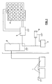
figure 1 shows a general circuit scheme of the additional autonomous power supply system according to the present invention. - In
figure 1 number 1 indicates the primary batteries of the vehicle. A heavy vehicle generally have two 12 V batteries connected in series in order to have a 24 V voltage at the external terminals. - Number 2 indicates a voltage divider which receives a 24 V voltage in input from the primary batteries 1 and provides a 12 V voltage in output to an additional battery system of the
hermetic type 3, which, according the invention, will be used for power supplying the accessories normally used in the vehicle's cabin, by means of the various 12 V sockets 6 available. - The recharging of the additional battery system of the
hermetic type 3 is carried out essentially in two ways: - when the vehicle engine is started, the recharging takes place by means of the primary batteries 1 and of the voltage divider 2 from 24 V to 12 V, when present, for example a 10 A DC/DC converter, and/or by means of an external recharging system, e.g. by means of one or more 12V
solar panels 4. - when the vehicle engine is stopped, the recharging takes place by means of the external system, while the connection with the primary batteries is interrupted; the latter being recovered only in case of absence of light, by means of the voltage divider 2, if the charging level is critical or in case of detected failure.
- Solar panels may be placed on the upper part of the vehicle; for example they may be of the flexible type in order to follow the outline of the surface where they are placed. It is possible to use solar panels which can provide currents of about 2 A and having a voltage of 14 V.
- A charge controller circuit 5 is also present and is suitable to control the charging of the additional
hermetic battery system 3 in the sense explained above. Moreover it disconnects the power supply of the additionalhermetic battery system 3 when the latter is full.
The charge controller may be an independent component, or its function may be performed by a variant of the voltage divider 2 whose input are also the solar panels. - The hermetic battery may be of a type known in the art, and is of a different type with respect to the primary batteries: it is small and less heavy, suitable for cyclic discharge, it may be easily placed in any place in the cabin, e.g. under the bed, it is of the maintenance-free type, it may be turned upside down, it does not have any cap, it may be positioned upside-down or laid horizontally, it does not suffer from complete discharge, therefore it may be discharged completely without having problems, while the primary batteries would have been damaged so that it would be necessary to replace them.
It can be recharged when the vehicle is started, while when the vehicle is stationary primary batteries are not affected and it is possible to use 12V solar panels. - This way the primary batteries of the vehicle may have dimensions suitable for power supplying only the primary functions of the vehicle, such as starting, turning the headlights on, power supplying the vehicular control unit: therefore less power is enough. The power is determined on the basis of regulations fixing the value of the starting current at -18 °C.
- For example, in case of large-sized industrial vehicle, primary batteries are now of the 220 Ah type, each of these weighing 58 Kg. While, using the system according to this invention, the batteries may be reduced to the 130 Ah type, each of these weighing 43 Kg, or 110 Ah, weighing 35 Kg.
- One of the batteries that may be used according to this invention is for example of the 32 Ah type, weighing 11 Kg, or of the 24 Ah type, weighing 7 Kg. Its cost and its weight are remarkably lower than the ones of an equivalent primary battery.
- It will be apparent to the person skilled in the art that other alternative and equivalent embodiments of the invention can be conceived and reduced to practice without departing from the scope of the invention.
- The advantages deriving from the use of this invention are evident, and result in:
- higher endurance with the engine stopped;
- smaller starting batteries;
- lower or zero current withdrawal from vehicle's batteries;
- smaller DC/DC converters being used;
- lowering of the stress for the alternator, which can be smaller;
- lower fuel consumption.
- From the description set forth above it will be possible for the person skilled in the art to embody the invention with no need of describing further construction details.
Claims (3)
- Additional autonomous power supply system for vehicle, especially for industrial or commercial vehicle, said vehicle being provided with primary batteries used only for power supplying the primary functions of the vehicle, said system comprising:- an additional system of one or more hermetic batteries (3), for power supplying the accessories used in the vehicle;- means for recharging (2, 4) said one or more hermetic batteries (3);- means for controlling said recharging (5), performing said control in such a way as:- when the vehicle engine is started, said recharging takes place by means of primary batteries (1), and/or by means of an external recharging system (4) belonging to said means for recharging;- when the vehicle engine is stopped, said recharging takes place by means of said external system, while the connection with the primary batteries is interrupted; the latter being recovered only in case of absence of light, if the charging level is critical or in case of detected failure.
- Additional autonomous power supply system for vehicle as in claim 1, wherein said primary batteries (1) provide current to said additional system of hermetic batteries (3) by means of a voltage divider (2) belonging to said recharging means.
- Additional autonomous power supply system for vehicle as in claim 1, wherein said external recharging system comprises solar panels (4).
Priority Applications (2)
| Application Number | Priority Date | Filing Date | Title |
|---|---|---|---|
| ES09425218.6T ES2584452T3 (en) | 2009-06-03 | 2009-06-03 | Additional autonomous power supply system for vehicles, in particular for commercial or industrial vehicles |
| EP09425218.6A EP2258579B1 (en) | 2009-06-03 | 2009-06-03 | Additional autonomous power supply system for vehicle, especially for industrial or commercial vehicle |
Applications Claiming Priority (1)
| Application Number | Priority Date | Filing Date | Title |
|---|---|---|---|
| EP09425218.6A EP2258579B1 (en) | 2009-06-03 | 2009-06-03 | Additional autonomous power supply system for vehicle, especially for industrial or commercial vehicle |
Publications (2)
| Publication Number | Publication Date |
|---|---|
| EP2258579A1 true EP2258579A1 (en) | 2010-12-08 |
| EP2258579B1 EP2258579B1 (en) | 2016-04-27 |
Family
ID=41278697
Family Applications (1)
| Application Number | Title | Priority Date | Filing Date |
|---|---|---|---|
| EP09425218.6A Active EP2258579B1 (en) | 2009-06-03 | 2009-06-03 | Additional autonomous power supply system for vehicle, especially for industrial or commercial vehicle |
Country Status (2)
| Country | Link |
|---|---|
| EP (1) | EP2258579B1 (en) |
| ES (1) | ES2584452T3 (en) |
Cited By (7)
| Publication number | Priority date | Publication date | Assignee | Title |
|---|---|---|---|---|
| US11235712B2 (en) | 2018-08-08 | 2022-02-01 | Uatc, Llc | Automatically adjustable partition wall for an autonomous vehicle |
| US11281216B2 (en) | 2018-08-08 | 2022-03-22 | Uatc, Llc | Systems and methods for providing a ridesharing vehicle service using an autonomous vehicle |
| US11340625B2 (en) | 2018-08-08 | 2022-05-24 | Uatc, Llc | Autonomous vehicle compatible robot |
| US11358521B2 (en) | 2018-08-08 | 2022-06-14 | Uatc, Llc | Vehicle wheel units |
| US11376992B2 (en) | 2018-08-08 | 2022-07-05 | Uatc, Llc | Automated vehicle seats |
| US11440440B2 (en) | 2018-08-08 | 2022-09-13 | Uatc, Llc | Modular autonomous-vehicle interior |
| US11608002B2 (en) | 2018-08-08 | 2023-03-21 | Uatc, Llc | Transportation receptacle for vehicles |
Citations (3)
| Publication number | Priority date | Publication date | Assignee | Title |
|---|---|---|---|---|
| DE3841769C1 (en) | 1988-12-12 | 1990-06-07 | Juergen 8014 Neubiberg De Wemhoener | Circuit for ensuring the provision of starting energy in motor vehicles with internal combustion engines |
| US5905356A (en) * | 1996-11-18 | 1999-05-18 | Wells; Gilbert Michael | Solar powered charger for vehicular accessories and cordless tools |
| WO2007025096A1 (en) * | 2005-08-24 | 2007-03-01 | Ward Thomas A | Hybrid vehicle with modular solar panel and battery charging system to supplement regenerative braking |
-
2009
- 2009-06-03 ES ES09425218.6T patent/ES2584452T3/en active Active
- 2009-06-03 EP EP09425218.6A patent/EP2258579B1/en active Active
Patent Citations (3)
| Publication number | Priority date | Publication date | Assignee | Title |
|---|---|---|---|---|
| DE3841769C1 (en) | 1988-12-12 | 1990-06-07 | Juergen 8014 Neubiberg De Wemhoener | Circuit for ensuring the provision of starting energy in motor vehicles with internal combustion engines |
| US5905356A (en) * | 1996-11-18 | 1999-05-18 | Wells; Gilbert Michael | Solar powered charger for vehicular accessories and cordless tools |
| WO2007025096A1 (en) * | 2005-08-24 | 2007-03-01 | Ward Thomas A | Hybrid vehicle with modular solar panel and battery charging system to supplement regenerative braking |
Cited By (16)
| Publication number | Priority date | Publication date | Assignee | Title |
|---|---|---|---|---|
| US11235712B2 (en) | 2018-08-08 | 2022-02-01 | Uatc, Llc | Automatically adjustable partition wall for an autonomous vehicle |
| US11281216B2 (en) | 2018-08-08 | 2022-03-22 | Uatc, Llc | Systems and methods for providing a ridesharing vehicle service using an autonomous vehicle |
| US11340625B2 (en) | 2018-08-08 | 2022-05-24 | Uatc, Llc | Autonomous vehicle compatible robot |
| US11358521B2 (en) | 2018-08-08 | 2022-06-14 | Uatc, Llc | Vehicle wheel units |
| US11376992B2 (en) | 2018-08-08 | 2022-07-05 | Uatc, Llc | Automated vehicle seats |
| US11377045B2 (en) | 2018-08-08 | 2022-07-05 | Uatc, Llc | Distinct user and item delivery for autonomous vehicles |
| US11440490B2 (en) | 2018-08-08 | 2022-09-13 | Uatc, Llc | Location-based checklist interface for autonomous vehicle users |
| US11440440B2 (en) | 2018-08-08 | 2022-09-13 | Uatc, Llc | Modular autonomous-vehicle interior |
| US11608002B2 (en) | 2018-08-08 | 2023-03-21 | Uatc, Llc | Transportation receptacle for vehicles |
| US11642985B2 (en) | 2018-08-08 | 2023-05-09 | Uatc, Llc | Automated vehicle seats |
| US11794671B2 (en) | 2018-08-08 | 2023-10-24 | Uatc, Llc | Automatically adjustable partition wall for an autonomous vehicle |
| US11835952B2 (en) | 2018-08-08 | 2023-12-05 | Uatc, Llc | Systems and methods for providing a ridesharing vehicle service using an autonomous vehicle |
| US11841709B2 (en) | 2018-08-08 | 2023-12-12 | Uatc, Llc | Autonomous vehicle compatible robot |
| US12187202B2 (en) | 2018-08-08 | 2025-01-07 | Aurora Operations, Inc. | Automatically adjustable partition wall for an autonomous vehicle |
| US12214698B2 (en) | 2018-08-08 | 2025-02-04 | Aurora Operations, Inc. | Automated vehicle seats |
| US12216476B2 (en) | 2018-08-08 | 2025-02-04 | Aurora Operations, Inc. | Autonomous vehicle compatible robot |
Also Published As
| Publication number | Publication date |
|---|---|
| ES2584452T3 (en) | 2016-09-27 |
| EP2258579B1 (en) | 2016-04-27 |
Similar Documents
| Publication | Publication Date | Title |
|---|---|---|
| KR101583340B1 (en) | Apparatus for battery control and method for battery control for electrical vehicles | |
| CN105324269B (en) | Utilize the battery charge controller of Vehicular solar battery | |
| KR101496483B1 (en) | Solar charged hybrid power system | |
| US10471837B2 (en) | Method for charging a direct current traction battery at a direct current charging pillar | |
| KR101743855B1 (en) | Charging control device using in-vehicle solar cell | |
| KR101617292B1 (en) | Electric vehicles and method for sub-battery charging control thereof | |
| EP2258579B1 (en) | Additional autonomous power supply system for vehicle, especially for industrial or commercial vehicle | |
| EP2596982A2 (en) | Power supply system for electric vehicle and control method thereof | |
| US20120286720A1 (en) | Jump-starting method and device for implementing the method | |
| US20120139338A1 (en) | High voltage system of electric vehicles | |
| CN102782980A (en) | Power supply system and electric vehicle | |
| US20130268158A1 (en) | Abnormality diagnosis apparatus for power control system | |
| CN103094948B (en) | Power supply system for electric vehicle and control method thereof | |
| KR102909364B1 (en) | Battery control method and battery system providing the same | |
| US10322687B2 (en) | Stabilization circuit for a vehicle electrical system | |
| KR20150127779A (en) | A bi-directional multi-voltage driving charger for multiple auxiliary batteries | |
| CN105966248A (en) | Method for voltage regulation of an electrical system of a motor vehicle | |
| US20100286856A1 (en) | Hybrid vehicle with a body builder equipment circuit and battery set | |
| JP2019071770A (en) | Supply of low voltage in-vehicle electrical system of electric drive vehicle | |
| CN110091815A (en) | Electric system for autonomous vehicle | |
| JP5598216B2 (en) | Vehicle power supply control device | |
| EP3678275A1 (en) | Recharging system for electric vehicles | |
| US12606038B2 (en) | Multi-energy portable power panel for vehicle | |
| CN115378062B (en) | Energy monitoring system for vehicles | |
| KR101187449B1 (en) | two direction regenerative braking control method of electric vehicle with non contact electromagnetic inductive charging |
Legal Events
| Date | Code | Title | Description |
|---|---|---|---|
| PUAI | Public reference made under article 153(3) epc to a published international application that has entered the european phase |
Free format text: ORIGINAL CODE: 0009012 |
|
| AK | Designated contracting states |
Kind code of ref document: A1 Designated state(s): AT BE BG CH CY CZ DE DK EE ES FI FR GB GR HR HU IE IS IT LI LT LU LV MC MK MT NL NO PL PT RO SE SI SK TR |
|
| AX | Request for extension of the european patent |
Extension state: AL BA RS |
|
| 17P | Request for examination filed |
Effective date: 20101203 |
|
| 17Q | First examination report despatched |
Effective date: 20101228 |
|
| GRAP | Despatch of communication of intention to grant a patent |
Free format text: ORIGINAL CODE: EPIDOSNIGR1 |
|
| INTG | Intention to grant announced |
Effective date: 20151110 |
|
| GRAS | Grant fee paid |
Free format text: ORIGINAL CODE: EPIDOSNIGR3 |
|
| GRAA | (expected) grant |
Free format text: ORIGINAL CODE: 0009210 |
|
| AK | Designated contracting states |
Kind code of ref document: B1 Designated state(s): AT BE BG CH CY CZ DE DK EE ES FI FR GB GR HR HU IE IS IT LI LT LU LV MC MK MT NL NO PL PT RO SE SI SK TR |
|
| REG | Reference to a national code |
Ref country code: GB Ref legal event code: FG4D |
|
| REG | Reference to a national code |
Ref country code: CH Ref legal event code: EP |
|
| REG | Reference to a national code |
Ref country code: AT Ref legal event code: REF Ref document number: 794348 Country of ref document: AT Kind code of ref document: T Effective date: 20160515 |
|
| REG | Reference to a national code |
Ref country code: IE Ref legal event code: FG4D |
|
| REG | Reference to a national code |
Ref country code: DE Ref legal event code: R096 Ref document number: 602009038182 Country of ref document: DE |
|
| REG | Reference to a national code |
Ref country code: CH Ref legal event code: NV Representative=s name: RENTSCH PARTNER AG, CH |
|
| REG | Reference to a national code |
Ref country code: FR Ref legal event code: PLFP Year of fee payment: 8 |
|
| REG | Reference to a national code |
Ref country code: NL Ref legal event code: FP |
|
| REG | Reference to a national code |
Ref country code: SE Ref legal event code: TRGR |
|
| REG | Reference to a national code |
Ref country code: LT Ref legal event code: MG4D |
|
| REG | Reference to a national code |
Ref country code: AT Ref legal event code: MK05 Ref document number: 794348 Country of ref document: AT Kind code of ref document: T Effective date: 20160427 |
|
| REG | Reference to a national code |
Ref country code: ES Ref legal event code: FG2A Ref document number: 2584452 Country of ref document: ES Kind code of ref document: T3 Effective date: 20160927 |
|
| PG25 | Lapsed in a contracting state [announced via postgrant information from national office to epo] |
Ref country code: FI Free format text: LAPSE BECAUSE OF FAILURE TO SUBMIT A TRANSLATION OF THE DESCRIPTION OR TO PAY THE FEE WITHIN THE PRESCRIBED TIME-LIMIT Effective date: 20160427 Ref country code: NO Free format text: LAPSE BECAUSE OF FAILURE TO SUBMIT A TRANSLATION OF THE DESCRIPTION OR TO PAY THE FEE WITHIN THE PRESCRIBED TIME-LIMIT Effective date: 20160727 Ref country code: PL Free format text: LAPSE BECAUSE OF FAILURE TO SUBMIT A TRANSLATION OF THE DESCRIPTION OR TO PAY THE FEE WITHIN THE PRESCRIBED TIME-LIMIT Effective date: 20160427 Ref country code: LT Free format text: LAPSE BECAUSE OF FAILURE TO SUBMIT A TRANSLATION OF THE DESCRIPTION OR TO PAY THE FEE WITHIN THE PRESCRIBED TIME-LIMIT Effective date: 20160427 |
|
| PG25 | Lapsed in a contracting state [announced via postgrant information from national office to epo] |
Ref country code: GR Free format text: LAPSE BECAUSE OF FAILURE TO SUBMIT A TRANSLATION OF THE DESCRIPTION OR TO PAY THE FEE WITHIN THE PRESCRIBED TIME-LIMIT Effective date: 20160728 Ref country code: HR Free format text: LAPSE BECAUSE OF FAILURE TO SUBMIT A TRANSLATION OF THE DESCRIPTION OR TO PAY THE FEE WITHIN THE PRESCRIBED TIME-LIMIT Effective date: 20160427 Ref country code: PT Free format text: LAPSE BECAUSE OF FAILURE TO SUBMIT A TRANSLATION OF THE DESCRIPTION OR TO PAY THE FEE WITHIN THE PRESCRIBED TIME-LIMIT Effective date: 20160829 Ref country code: AT Free format text: LAPSE BECAUSE OF FAILURE TO SUBMIT A TRANSLATION OF THE DESCRIPTION OR TO PAY THE FEE WITHIN THE PRESCRIBED TIME-LIMIT Effective date: 20160427 Ref country code: LV Free format text: LAPSE BECAUSE OF FAILURE TO SUBMIT A TRANSLATION OF THE DESCRIPTION OR TO PAY THE FEE WITHIN THE PRESCRIBED TIME-LIMIT Effective date: 20160427 |
|
| PG25 | Lapsed in a contracting state [announced via postgrant information from national office to epo] |
Ref country code: BE Free format text: LAPSE BECAUSE OF FAILURE TO SUBMIT A TRANSLATION OF THE DESCRIPTION OR TO PAY THE FEE WITHIN THE PRESCRIBED TIME-LIMIT Effective date: 20160427 |
|
| REG | Reference to a national code |
Ref country code: DE Ref legal event code: R097 Ref document number: 602009038182 Country of ref document: DE |
|
| PG25 | Lapsed in a contracting state [announced via postgrant information from national office to epo] |
Ref country code: EE Free format text: LAPSE BECAUSE OF FAILURE TO SUBMIT A TRANSLATION OF THE DESCRIPTION OR TO PAY THE FEE WITHIN THE PRESCRIBED TIME-LIMIT Effective date: 20160427 Ref country code: SK Free format text: LAPSE BECAUSE OF FAILURE TO SUBMIT A TRANSLATION OF THE DESCRIPTION OR TO PAY THE FEE WITHIN THE PRESCRIBED TIME-LIMIT Effective date: 20160427 Ref country code: DK Free format text: LAPSE BECAUSE OF FAILURE TO SUBMIT A TRANSLATION OF THE DESCRIPTION OR TO PAY THE FEE WITHIN THE PRESCRIBED TIME-LIMIT Effective date: 20160427 Ref country code: RO Free format text: LAPSE BECAUSE OF FAILURE TO SUBMIT A TRANSLATION OF THE DESCRIPTION OR TO PAY THE FEE WITHIN THE PRESCRIBED TIME-LIMIT Effective date: 20160427 Ref country code: CZ Free format text: LAPSE BECAUSE OF FAILURE TO SUBMIT A TRANSLATION OF THE DESCRIPTION OR TO PAY THE FEE WITHIN THE PRESCRIBED TIME-LIMIT Effective date: 20160427 Ref country code: MC Free format text: LAPSE BECAUSE OF FAILURE TO SUBMIT A TRANSLATION OF THE DESCRIPTION OR TO PAY THE FEE WITHIN THE PRESCRIBED TIME-LIMIT Effective date: 20160427 |
|
| PLBE | No opposition filed within time limit |
Free format text: ORIGINAL CODE: 0009261 |
|
| STAA | Information on the status of an ep patent application or granted ep patent |
Free format text: STATUS: NO OPPOSITION FILED WITHIN TIME LIMIT |
|
| REG | Reference to a national code |
Ref country code: IE Ref legal event code: MM4A |
|
| 26N | No opposition filed |
Effective date: 20170130 |
|
| REG | Reference to a national code |
Ref country code: FR Ref legal event code: PLFP Year of fee payment: 9 |
|
| PG25 | Lapsed in a contracting state [announced via postgrant information from national office to epo] |
Ref country code: SI Free format text: LAPSE BECAUSE OF FAILURE TO SUBMIT A TRANSLATION OF THE DESCRIPTION OR TO PAY THE FEE WITHIN THE PRESCRIBED TIME-LIMIT Effective date: 20160427 Ref country code: IE Free format text: LAPSE BECAUSE OF NON-PAYMENT OF DUE FEES Effective date: 20160603 |
|
| REG | Reference to a national code |
Ref country code: CH Ref legal event code: PCAR Free format text: NEW ADDRESS: BELLERIVESTRASSE 203 POSTFACH, 8034 ZUERICH (CH) |
|
| PG25 | Lapsed in a contracting state [announced via postgrant information from national office to epo] |
Ref country code: HU Free format text: LAPSE BECAUSE OF FAILURE TO SUBMIT A TRANSLATION OF THE DESCRIPTION OR TO PAY THE FEE WITHIN THE PRESCRIBED TIME-LIMIT; INVALID AB INITIO Effective date: 20090603 Ref country code: CY Free format text: LAPSE BECAUSE OF FAILURE TO SUBMIT A TRANSLATION OF THE DESCRIPTION OR TO PAY THE FEE WITHIN THE PRESCRIBED TIME-LIMIT Effective date: 20160427 |
|
| PG25 | Lapsed in a contracting state [announced via postgrant information from national office to epo] |
Ref country code: TR Free format text: LAPSE BECAUSE OF FAILURE TO SUBMIT A TRANSLATION OF THE DESCRIPTION OR TO PAY THE FEE WITHIN THE PRESCRIBED TIME-LIMIT Effective date: 20160427 Ref country code: LU Free format text: LAPSE BECAUSE OF NON-PAYMENT OF DUE FEES Effective date: 20160603 Ref country code: MK Free format text: LAPSE BECAUSE OF FAILURE TO SUBMIT A TRANSLATION OF THE DESCRIPTION OR TO PAY THE FEE WITHIN THE PRESCRIBED TIME-LIMIT Effective date: 20160427 Ref country code: IS Free format text: LAPSE BECAUSE OF FAILURE TO SUBMIT A TRANSLATION OF THE DESCRIPTION OR TO PAY THE FEE WITHIN THE PRESCRIBED TIME-LIMIT Effective date: 20160427 Ref country code: MT Free format text: LAPSE BECAUSE OF NON-PAYMENT OF DUE FEES Effective date: 20160630 |
|
| REG | Reference to a national code |
Ref country code: FR Ref legal event code: PLFP Year of fee payment: 10 |
|
| PG25 | Lapsed in a contracting state [announced via postgrant information from national office to epo] |
Ref country code: BG Free format text: LAPSE BECAUSE OF FAILURE TO SUBMIT A TRANSLATION OF THE DESCRIPTION OR TO PAY THE FEE WITHIN THE PRESCRIBED TIME-LIMIT Effective date: 20160427 |
|
| P01 | Opt-out of the competence of the unified patent court (upc) registered |
Effective date: 20230523 |
|
| PGFP | Annual fee paid to national office [announced via postgrant information from national office to epo] |
Ref country code: DE Payment date: 20250626 Year of fee payment: 17 |
|
| PGFP | Annual fee paid to national office [announced via postgrant information from national office to epo] |
Ref country code: GB Payment date: 20250617 Year of fee payment: 17 |
|
| PGFP | Annual fee paid to national office [announced via postgrant information from national office to epo] |
Ref country code: NL Payment date: 20250624 Year of fee payment: 17 |
|
| PGFP | Annual fee paid to national office [announced via postgrant information from national office to epo] |
Ref country code: FR Payment date: 20250624 Year of fee payment: 17 |
|
| PGFP | Annual fee paid to national office [announced via postgrant information from national office to epo] |
Ref country code: SE Payment date: 20250619 Year of fee payment: 17 |
|
| PGFP | Annual fee paid to national office [announced via postgrant information from national office to epo] |
Ref country code: ES Payment date: 20250710 Year of fee payment: 17 |
|
| PGFP | Annual fee paid to national office [announced via postgrant information from national office to epo] |
Ref country code: IT Payment date: 20250612 Year of fee payment: 17 |
|
| PGFP | Annual fee paid to national office [announced via postgrant information from national office to epo] |
Ref country code: CH Payment date: 20250701 Year of fee payment: 17 |