EP2257865B1 - Reduction of power consumption in remote control electronics - Google Patents
Reduction of power consumption in remote control electronics Download PDFInfo
- Publication number
- EP2257865B1 EP2257865B1 EP09724798.5A EP09724798A EP2257865B1 EP 2257865 B1 EP2257865 B1 EP 2257865B1 EP 09724798 A EP09724798 A EP 09724798A EP 2257865 B1 EP2257865 B1 EP 2257865B1
- Authority
- EP
- European Patent Office
- Prior art keywords
- remote control
- user
- control device
- remote
- motion sensors
- Prior art date
- Legal status (The legal status is an assumption and is not a legal conclusion. Google has not performed a legal analysis and makes no representation as to the accuracy of the status listed.)
- Active
Links
Images



Classifications
-
- G—PHYSICS
- G06—COMPUTING OR CALCULATING; COUNTING
- G06F—ELECTRIC DIGITAL DATA PROCESSING
- G06F1/00—Details not covered by groups G06F3/00 - G06F13/00 and G06F21/00
- G06F1/26—Power supply means, e.g. regulation thereof
- G06F1/32—Means for saving power
- G06F1/3203—Power management, i.e. event-based initiation of a power-saving mode
- G06F1/3234—Power saving characterised by the action undertaken
- G06F1/3296—Power saving characterised by the action undertaken by lowering the supply or operating voltage
-
- G—PHYSICS
- G06—COMPUTING OR CALCULATING; COUNTING
- G06F—ELECTRIC DIGITAL DATA PROCESSING
- G06F1/00—Details not covered by groups G06F3/00 - G06F13/00 and G06F21/00
- G06F1/26—Power supply means, e.g. regulation thereof
- G06F1/32—Means for saving power
- G06F1/3203—Power management, i.e. event-based initiation of a power-saving mode
-
- G—PHYSICS
- G06—COMPUTING OR CALCULATING; COUNTING
- G06F—ELECTRIC DIGITAL DATA PROCESSING
- G06F1/00—Details not covered by groups G06F3/00 - G06F13/00 and G06F21/00
- G06F1/26—Power supply means, e.g. regulation thereof
- G06F1/32—Means for saving power
- G06F1/3203—Power management, i.e. event-based initiation of a power-saving mode
- G06F1/3206—Monitoring of events, devices or parameters that trigger a change in power modality
- G06F1/3231—Monitoring the presence, absence or movement of users
-
- G—PHYSICS
- G06—COMPUTING OR CALCULATING; COUNTING
- G06F—ELECTRIC DIGITAL DATA PROCESSING
- G06F1/00—Details not covered by groups G06F3/00 - G06F13/00 and G06F21/00
- G06F1/26—Power supply means, e.g. regulation thereof
- G06F1/32—Means for saving power
- G06F1/3203—Power management, i.e. event-based initiation of a power-saving mode
- G06F1/3234—Power saving characterised by the action undertaken
- G06F1/325—Power saving in peripheral device
- G06F1/3259—Power saving in cursor control device, e.g. mouse, joystick, trackball
-
- G—PHYSICS
- G06—COMPUTING OR CALCULATING; COUNTING
- G06F—ELECTRIC DIGITAL DATA PROCESSING
- G06F3/00—Input arrangements for transferring data to be processed into a form capable of being handled by the computer; Output arrangements for transferring data from processing unit to output unit, e.g. interface arrangements
- G06F3/01—Input arrangements or combined input and output arrangements for interaction between user and computer
- G06F3/03—Arrangements for converting the position or the displacement of a member into a coded form
- G06F3/033—Pointing devices displaced or positioned by the user, e.g. mice, trackballs, pens or joysticks; Accessories therefor
- G06F3/0346—Pointing devices displaced or positioned by the user, e.g. mice, trackballs, pens or joysticks; Accessories therefor with detection of the device orientation or free movement in a three-dimensional [3D] space, e.g. 3D mice, 6-DOF [six degrees of freedom] pointers using gyroscopes, accelerometers or tilt-sensors
-
- G—PHYSICS
- G08—SIGNALLING
- G08C—TRANSMISSION SYSTEMS FOR MEASURED VALUES, CONTROL OR SIMILAR SIGNALS
- G08C17/00—Arrangements for transmitting signals characterised by the use of a wireless electrical link
- G08C17/02—Arrangements for transmitting signals characterised by the use of a wireless electrical link using a radio link
-
- H—ELECTRICITY
- H02—GENERATION; CONVERSION OR DISTRIBUTION OF ELECTRIC POWER
- H02J—ELECTRIC POWER NETWORKS; CIRCUIT ARRANGEMENTS OR SYSTEMS FOR SUPPLYING OR DISTRIBUTING ELECTRIC POWER; SYSTEMS FOR STORING ELECTRIC ENERGY
- H02J9/00—Circuit arrangements for emergency or stand-by power supply, e.g. for emergency lighting
- H02J9/005—Circuit arrangements for emergency or stand-by power supply, e.g. for emergency lighting using a power saving mode
-
- G—PHYSICS
- G08—SIGNALLING
- G08C—TRANSMISSION SYSTEMS FOR MEASURED VALUES, CONTROL OR SIMILAR SIGNALS
- G08C2201/00—Transmission systems of control signals via wireless link
- G08C2201/10—Power supply of remote control devices
- G08C2201/12—Power saving techniques of remote control or controlled devices
-
- G—PHYSICS
- G08—SIGNALLING
- G08C—TRANSMISSION SYSTEMS FOR MEASURED VALUES, CONTROL OR SIMILAR SIGNALS
- G08C2201/00—Transmission systems of control signals via wireless link
- G08C2201/30—User interface
- G08C2201/32—Remote control based on movements, attitude of remote control device
-
- Y—GENERAL TAGGING OF NEW TECHNOLOGICAL DEVELOPMENTS; GENERAL TAGGING OF CROSS-SECTIONAL TECHNOLOGIES SPANNING OVER SEVERAL SECTIONS OF THE IPC; TECHNICAL SUBJECTS COVERED BY FORMER USPC CROSS-REFERENCE ART COLLECTIONS [XRACs] AND DIGESTS
- Y02—TECHNOLOGIES OR APPLICATIONS FOR MITIGATION OR ADAPTATION AGAINST CLIMATE CHANGE
- Y02D—CLIMATE CHANGE MITIGATION TECHNOLOGIES IN INFORMATION AND COMMUNICATION TECHNOLOGIES [ICT], I.E. INFORMATION AND COMMUNICATION TECHNOLOGIES AIMING AT THE REDUCTION OF THEIR OWN ENERGY USE
- Y02D10/00—Energy efficient computing, e.g. low power processors, power management or thermal management
-
- Y—GENERAL TAGGING OF NEW TECHNOLOGICAL DEVELOPMENTS; GENERAL TAGGING OF CROSS-SECTIONAL TECHNOLOGIES SPANNING OVER SEVERAL SECTIONS OF THE IPC; TECHNICAL SUBJECTS COVERED BY FORMER USPC CROSS-REFERENCE ART COLLECTIONS [XRACs] AND DIGESTS
- Y02—TECHNOLOGIES OR APPLICATIONS FOR MITIGATION OR ADAPTATION AGAINST CLIMATE CHANGE
- Y02D—CLIMATE CHANGE MITIGATION TECHNOLOGIES IN INFORMATION AND COMMUNICATION TECHNOLOGIES [ICT], I.E. INFORMATION AND COMMUNICATION TECHNOLOGIES AIMING AT THE REDUCTION OF THEIR OWN ENERGY USE
- Y02D30/00—Reducing energy consumption in communication networks
- Y02D30/50—Reducing energy consumption in communication networks in wire-line communication networks, e.g. low power modes or reduced link rate
Definitions
- the present invention relates generally to remote control electronics, and more particularly to an apparatus and method to conserve power consumption of remote control electronics.
- GB2398138 describes an apparatus and method for activating a user input device from a sleep or power saving mode comprising a system to sense an electrical property associated with the proximity of the user's hand and send a wake up signal to a controller if the electrical property exceeds a threshold value.
- the input device is a cordless mouse communicating with a computer system.
- the sensor may be an antenna connected to a signal source which may be dedicated or the system clock.
- the antenna may also comprise a conductive portion on the housing of the apparatus.
- the signal source may also be an RF generator which may be used in the communication with the computer.
- the sensor may be a capacitive or pressure sensor.
- the threshold value may be adaptively adjusted with measuring being completed on an adjustable period. Further embodiments of the invention include the wakeup signal being generated by an accelerometer or listening for packets from the computer system. In a further embodiment monitoring for activity may be done using different clock frequencies.
- US2003058222 describes capacitive proximity sensing that is carried out by detecting a relative change in the capacitance of a "scoop" capacitor formed by a conductor and a surrounding ground plane.
- the conductor may be a plate provided in the form of an adhesive label printed with conductive ink.
- Charge is transferred between the "scoop” capacitor and a relatively large “bucket” capacitor, and a voltage of the bucket capacitor is applied to an input threshold switch.
- a state transition e.g., from low to high, or high to low
- the presence or absence of an object or body portion in close proximity to or contact with a device can be determined by comparing TouchVal with a predetermined threshold value (TouchOff). TouchOff can be adjusted to take into account environmentally induced (non-touch related) changes in the capacitance of the scoop capacitor.
- Power management is provided in a user operated data input device utilizing proximity sensing and switching between three or more power states. Switching between the power states occurs based upon the presence or absence of input activity, and an operation instrumentality (e.g., a hand) in close proximity to or contact with the device.
- switching to and from a BEACON state which provides a reduced flash rate of a surface illuminating light source, is carried out based upon a detected presence or absence of a trackable surface.
- US2007102525 describes a system and method for activating an electronic device from a low power state.
- an activation circuit for an electronic device is provided.
- the circuit comprises: a motion sensor circuit; an input device; and a monitoring circuit connected to the input device.
- the monitoring circuit provides power to the input device when the motion sensor circuit detects a notable movement of the device and selectively generates an activation signal used to activate the electronic device to a higher power state in response to receiving a notable signal received from the input device.
- US2005/174324 describes systems and methods that provide a free space pointing device and methods for free space pointing which provide accurate translation of movement of the free space pointing device into user interface commands, e.g., cursor movement.
- the free space pointing device includes a plurality of accelerometers. This document does not disclose reducing data transmission of motion data when it is detected that user is not holding the device.
- control interface should be interpreted as including, but not limited to, buttons, touchpads, switches, and the like.
- One embodiment takes the form of an apparatus for reducing power consumption in remote control electronics.
- the embodiment may include a remote control capable of controlling multiple pieces of remote electronic devices, such as a set-top box receiver or a display screen. Control may be exercised by, for example, actuating buttons on the remote control, contact with a touchpad, or may be through moving the remote control spatially with respect to the electronic device being controlled. For example, the remote control controls the position of objects and/or icons displayed on a display screen by moving the remote control spatially relative to the screen.
- the embodiment further includes a capacitive sensor that selectively operationally couples at least certain power consuming elements of the remote control electronics to a power source based on whether a user is holding the remote control.
- a capacitive sensor that selectively operationally couples at least certain power consuming elements of the remote control electronics to a power source based on whether a user is holding the remote control.
- Exemplary portions of the remote control device that may be selectively coupled to and from the power source include gyroscopes, accelerometers, touch pads, data link circuitry and so forth.
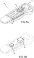
- Fig.1A depicts a top perspective view of an exemplary remote control 100 according to a first embodiment.
- the remote control 100 is shown as a single handheld device, other implementations are possible.
- the remote control 100 may be implemented in the form of a remote keyboard or multiple handheld devices.
- the remote control 100 is powered by one or more batteries (not shown) and includes one or more buttons 110. These buttons 110 allow a user of the remote control 100 to activate and deactivate one or more remote electronic devices 200, as shown in Fig. 2 .
- the remote electronic devices 200 that are controllable with the remote control 100 may be any variety of electronics, such as set-top boxes (STBs), TVs, digital video recorders (DVRs) for other receivers used in receiving television programming across any suitable wired or wireless network.
- STBs set-top boxes
- DVRs digital video recorders
- One such STB is the ViP722ksu model manufactured by EchoStar Technologies LLC of Englewood, CO, United States.
- the remote control 100 and the remote electronic devices 200 communicate using many different signal types and communication protocols.
- the remote control 100 may utilize radio frequency (RF), infrared (IR), Bluetooth, ZigBee, EC-Net, etc., transmitters and receivers 115 to communicate with the electronic devices.
- RF radio frequency
- IR infrared
- Bluetooth ZigBee
- EC-Net EC-Net
- transmitters and receivers 115 to communicate with the electronic devices.
- Exemplary transmit and receive protocols include IEEE 802.15.1 and 802.15.4.
- the remote control 100 may be configured to provide the entire functionality of the remote electronic device being controlled.
- the electronic devices 200 may couple to a television 210.
- the electronic devices 200 may couple to the television 210 in many ways, both physically and electrically, and that they may be a single unit.
- the electronic devices may operationally couple to another device or, in some embodiments, no device at all.
- the television 210 and/or remote devices 200 may be configured to present a user selection menu 220 to the user.
- User selection menu 220 may be manipulated by the user of the remote control 100 to select various options presented on the television 210. As one example, as shown in Fig.
- the user selection menu 220 may be used to adjust a slider 230 in order to display different movies available for purchase.
- the user selection menu 220 may appear to move not only in the X and Y directions, but also the Z direction.
- the remote control 100 may use several different mechanisms for controlling the user selection menu 220.
- a touch pad 120 is shown by which a user of the remote control 100 can move the user selection menu 220.
- the remote control 100 may include one or more gyroscopes 130 and/or accelerometers 140 for detecting a user's movement of the remote control in three dimensions and, consequently, the user's desired movement of the user selection menu 220. Regardless of whether the remote control 100 uses the touch pad 120, the gyroscopes 130, or the accelerometers 140, operating these devices may cause the remote control 100 to draw heavily from its internal power supply (such as a battery).
- the remote control 100 includes one or more capacitive sensors 150 that detect whether the remote control 100 is being held by a user and may facilitate adjusting the power consumption of high current consuming circuitry accordingly.
- the capacitive sensors 150 are placed along the periphery of the remote control 100 where the user's hands touch the remote control 100, but they may be located anywhere on the remote control 100.
- Fig. 1C illustrates a top plan view of the remote control 100 showing the capacitive sensors 150 on opposite sides of the remote control 100.
- inductive or resistive sensors may be used that detect the electrical properties of a user's body by forming an electrical network with the user's body.
- the capacitive sensors may be used on remote devices other than the handheld remote controls depicted in Fig. 1A-1C .
- the concepts may be applied to head gear or chest straps worn by the user.
- Fig. 3A represents a cross sectional view of the remote control 100, with the capacitive sensor 150 shown in detail.
- the capacitive sensor 150 includes a plurality of electrodes 310 and 320, such as one or more positive electrodes 310 as well as one or more negative electrodes 320.
- the positive and negative electrodes 310 and 320 are sandwiched between a dielectric 330.
- the positive electrode 310 is separated from the negative electrodes 320 by distances d 1 and d 2 .
- distances d 1 and d 2 are equal to each other, although in other embodiments they may not be.
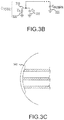
- Fig. 3B shows a schematic representation of the total capacitance C TOTAL of the capacitive sensor 150 from Fig.
- C TOTAL ⁇ A d 1 + d 2 d 1 ⁇ d 2
- ⁇ 1 and ⁇ 2 may be reflected in the calculation as shown in Equation (2), below.
- ⁇ 1 reflects the dielectric constant of the material in the distance d 1
- ⁇ 2 reflects the dielectric constant of the material in the distance d 2 .
- the value of C TOTAL is tuned by varying the thickness of the dielectrics of the material 330 i.e., modifying distances d 1 and d 2 .
- redundant electrodes may be implemented in place or in addition to either electrodes 310 or 320, and during operation the value of C TOTAL is tuned by selectively coupling in and out these redundant electrodes.
- C TOTAL A ⁇ 2 ⁇ d 1 + ⁇ 1 ⁇ d 2 d 1 ⁇ d 2
- a capacitor C HUMAN schematically represents the capacitance resulting from a user picking up the remote control 100.
- Capacitor C HUMAN generally has a value less than 300 pF, although in some implementations, this value is much smaller. It should be recognized that regardless of the implementation specific size of C HUMAN , C HUMAN relates to an expected capacitance value associated with the user holding the remote control 100.
- the capacitive sensor 150 may be implemented in a variety of forms, including as traces on either rigid circuit boards or flexible circuit boards. Regardless of whether the capacitive sensor 150 is implemented on rigid or flexible circuit boards or in another fashion, the positive and negative electrodes 310 and 320 may be maintained substantially parallel such that the separation distances d 1 and d 2 remain constant over the separation area A. In some embodiments, the positive and negative electrodes 310 and 320 are implemented in unused space along the circuit board housing additional electrical components of the remote control 100. Additionally, in some embodiments, the capacitive sensor 150 running along the periphery of the remote control may be covered by an overlay 340 (see Fig. 3C ) to protect the positive and negative electrodes 310 and 320.
- Fig. 3C represents the cross sectional view of the remote control from Fig. 3A , including an overlay.
- the overlay 340 may be any variety of material, such as plastic or glass, and Equations (1) and (2) would be modified accordingly to reflect the new value for C TOTAL accounting for the dielectric of overlay 340.
- Fig. 4 is a block diagram of the remote control 100 according to some embodiments.
- the remote control includes a microprocessor 400 that couples to the buttons 110, the touch pad 120, the gyroscopes 130, the accelerometers 140, the transmitter/receiver block 115, the capacitive sensor 150, batteries 405 and sensing circuitry 410.
- the microprocessor 400 transmits and receives signals to these system components and enables one or more of them to enter a low power state depending upon readings from the capacitive sensor 150.
- the low power state may include selectively decoupling one or more of the touch pad 120, the gyroscopes 130, and/or the accelerometers 140 from the batteries 405, while still allowing the microprocessor 400 to be coupled to the batteries 405. In this manner, the microprocessor 400 may receive indications from the capacitive sensor 150 as to whether a user is holding the remote control 100.
- a switch 415 (such as a single transistor) may be used to shut down any portion of remote control 100 based on the presence of a predetermined capacitance.
- a device may have an enable/disable function that can be controlled by the sense circuitry 410.
- power to the remote control 100 may be provided via a voltage regulator in the event that the power required by the remote control does not match the power provided by the batteries 405. Accordingly, the switch 415 may be coupled to an enable/disable function of such a regulator instead of the batteries 405.
- the microprocessor 400 may adjust the frequency of communication between the transmitter/receiver block 115 and the device that the remote control 100 is controlling, or alternatively, the information communicated between the remote control 100 and the device that the remote control 100 is controlling.
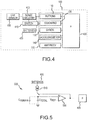
- Fig. 5 illustrates one of the many exemplary detection circuits that may be implemented as sense circuitry 410.
- the exemplary circuit 410 includes a current source 510 that couples to a power source, which in the case of the remote control 100 is the batteries 405.
- the current source 510 couples to the capacitance shown in Fig. 3B , C TOTAL and optionally CHUMAN when present, through a switch 520 that is controlled by an amplifier 530.
- the amplifier 530 is incorporated within the microcontroller 400.
- the amplifier 530 has a negative terminal coupled to a reference voltage V REF and a positive terminal coupled to C TOTAL (and optionally C HUMAN , when present).
- the output of the amplifier 530 controls the switch 520 to provide negative feedback and maintain the voltage at the positive terminal of the amplifier at V REF .
- the capacitance CHUMAN is present and CHUMAN is electrically in parallel with C TOTAL , which increases the value of the capacitance at the positive node of the amplifier 530.
- Increasing the capacitance at the positive terminal of the amplifier 530 decreases the overall voltage.
- the amplifier 530 provides negative feedback by regulating switch 520 to allow more current to flow in the combination of C TOTAL and CHUMAN. This, in turn, increases the voltage at the positive terminal of the amplifier 530 until it equals the voltage V REF again.
- the microprocessor (from Fig.
- the microprocessor 400 may perform various signal processing tasks on this data, including determining whether a user is holding the remote 100, de-bouncing the circuit 410, and/or re-calibrating C TOTAL by using the redundant connections described above.
- Fig. 6 illustrates an exemplary algorithm 600 implemented by the remote control 100 according to some embodiments not part of the claimed invention.
- the capacitive sensor 150 determines if someone is holding the remote control 100. The acts performed in block 610 may be performed using the circuitry 410 shown in Fig. 5 .
- a timer is initiated. The timer may be initiated from within the microprocessor 400, or elsewhere using specialized timer circuitry. This timer may be initialized each time a user has moved the remote control.
- the microprocessor 400 may then determine, in decision block 620, whether the capacitance is equal to or below C TOTAL (i.e., the user is not holding the remote control 100) or greater than this value (i.e., the user is holding the remote control 100). If the capacitance has not changed and still equals C TOTAL , the microprocessor may cause the remote control 100 to enter a low power mode by powering down one or more of the power intensive modules as shown in block 630. For example, the gyroscopes 130 and/or accelerometers 140 may be powered down.
- the microprocessor may cause the remote control 100 to wake up from a low power mode as shown in block 640. This may include waking up one or more of the modules previously powered down in block 630. In one embodiment, the time it takes to wake up the remote control 100 from the low power mode may be less than or equal to 100 milliseconds.
- the microprocessor may direct the sense circuitry to enter a low power state. For example, the sense circuitry 410 may be directed to power down every 50 milliseconds if the timer indicates no movement of the remote control.
- the frequency with which algorithm 600 is executed by the remote control 100 may vary based on the operational state of the remote control 100. For example, if the remote control 100 is in a low power mode algorithm 600 may be executed less frequently (based on value of initiated timer) than if the remote control 100 is "woken up".
Landscapes
- Engineering & Computer Science (AREA)
- Theoretical Computer Science (AREA)
- Physics & Mathematics (AREA)
- General Engineering & Computer Science (AREA)
- General Physics & Mathematics (AREA)
- Human Computer Interaction (AREA)
- Business, Economics & Management (AREA)
- Emergency Management (AREA)
- Power Engineering (AREA)
- Computer Networks & Wireless Communication (AREA)
- Selective Calling Equipment (AREA)
- Details Of Television Systems (AREA)
Description
- The present invention relates generally to remote control electronics, and more particularly to an apparatus and method to conserve power consumption of remote control electronics.
- Electronic devices are ubiquitous in society and can be found in everything from toaster ovens to set-top cable boxes. With the proliferation of integrated circuitry, these electronic devices are becoming more and more sophisticated. Many of these electronic devices-especially consumer electronic devices-include the ability to be remotely controlled by a user. The user expects to be able to harness the full functionality of the particular electronic device remotely, and therefore, the remote control electronics are also becoming more and more sophisticated. This increased sophistication of the remote control electronics presents special power consumption problems because the remote control electronics are usually battery powered.
- Thus, there is a need for an apparatus and method for reducing power consumption of remote control electronics.
-
GB2398138 -
US2003058222 describes capacitive proximity sensing that is carried out by detecting a relative change in the capacitance of a "scoop" capacitor formed by a conductor and a surrounding ground plane. The conductor may be a plate provided in the form of an adhesive label printed with conductive ink. Charge is transferred between the "scoop" capacitor and a relatively large "bucket" capacitor, and a voltage of the bucket capacitor is applied to an input threshold switch. A state transition (e.g., from low to high, or high to low) of the input threshold switch is detected and a value (TouchVal) indicative of a number of cycles of charge transfer required to reach the state transition is determined. The presence or absence of an object or body portion in close proximity to or contact with a device can be determined by comparing TouchVal with a predetermined threshold value (TouchOff). TouchOff can be adjusted to take into account environmentally induced (non-touch related) changes in the capacitance of the scoop capacitor. Power management is provided in a user operated data input device utilizing proximity sensing and switching between three or more power states. Switching between the power states occurs based upon the presence or absence of input activity, and an operation instrumentality (e.g., a hand) in close proximity to or contact with the device. In an optical surface tracking cursor control device embodiment, switching to and from a BEACON state, which provides a reduced flash rate of a surface illuminating light source, is carried out based upon a detected presence or absence of a trackable surface. -
US2007102525 describes a system and method for activating an electronic device from a low power state. In the system, an activation circuit for an electronic device is provided. The circuit comprises: a motion sensor circuit; an input device; and a monitoring circuit connected to the input device. The monitoring circuit provides power to the input device when the motion sensor circuit detects a notable movement of the device and selectively generates an activation signal used to activate the electronic device to a higher power state in response to receiving a notable signal received from the input device. -
US2005/174324 describes systems and methods that provide a free space pointing device and methods for free space pointing which provide accurate translation of movement of the free space pointing device into user interface commands, e.g., cursor movement. The free space pointing device includes a plurality of accelerometers. This document does not disclose reducing data transmission of motion data when it is detected that user is not holding the device. - The invention is defined in the independent claims, to which the reader is now directed. Preferred or advantageous embodiments are set out in the dependent claims.
-
-
Fig.1A depicts an oblique view of an exemplary remote control according to one embodiment; -
Fig. 1B shows a phantom perspective view of the remote control including additional components; -
Fig. 1C illustrates a top plan view of the remote control with capacitive sensors; -
Fig. 2 illustrates the remote control operating one or more exemplary remote electronic devices; and -
Fig. 3A depicts a cross sectional view of the remote control showing the capacitive sensors; -
Fig. 3B shows a schematic representation of the capacitive sensor; -
Fig. 3C represents the cross sectional view of the remote control fromFig. 3A , including an overlay; -
Fig. 4 depicts a block diagram of the remote control; -
Fig. 5 illustrates an exemplary detection circuit; and -
Fig. 6 represents an algorithm performed by the remote control. - The use of the same reference symbols in different drawings indicates similar or identical items.
- The following discussion describes various embodiments that may reduce consumption in certain electronic devices. Although one or more of these embodiments may be described in detail, the embodiments disclosed should not be interpreted or otherwise used as limiting the scope of the disclosure. In addition, one skilled in the art will understand that the following description has broad application, and the discussion of any embodiment is meant only to be exemplary, and is not intended to intimate that the scope of the disclosure is limited to these embodiments. References to "control interface" should be interpreted as including, but not limited to, buttons, touchpads, switches, and the like.
- One embodiment takes the form of an apparatus for reducing power consumption in remote control electronics. The embodiment may include a remote control capable of controlling multiple pieces of remote electronic devices, such as a set-top box receiver or a display screen. Control may be exercised by, for example, actuating buttons on the remote control, contact with a touchpad, or may be through moving the remote control spatially with respect to the electronic device being controlled. For example, the remote control controls the position of objects and/or icons displayed on a display screen by moving the remote control spatially relative to the screen.
- The embodiment further includes a capacitive sensor that selectively operationally couples at least certain power consuming elements of the remote control electronics to a power source based on whether a user is holding the remote control. Exemplary portions of the remote control device that may be selectively coupled to and from the power source include gyroscopes, accelerometers, touch pads, data link circuitry and so forth.
-
Fig.1A depicts a top perspective view of an exemplaryremote control 100 according to a first embodiment. It should be noted that although theremote control 100 is shown as a single handheld device, other implementations are possible. For example, theremote control 100 may be implemented in the form of a remote keyboard or multiple handheld devices. In any event, theremote control 100 is powered by one or more batteries (not shown) and includes one ormore buttons 110. Thesebuttons 110 allow a user of theremote control 100 to activate and deactivate one or more remoteelectronic devices 200, as shown inFig. 2 . The remoteelectronic devices 200 that are controllable with theremote control 100 may be any variety of electronics, such as set-top boxes (STBs), TVs, digital video recorders (DVRs) for other receivers used in receiving television programming across any suitable wired or wireless network. One such STB is the ViP722ksu model manufactured by EchoStar Technologies LLC of Englewood, CO, United States. - The
remote control 100 and the remoteelectronic devices 200 communicate using many different signal types and communication protocols. For example, as shown inFig. 1A , theremote control 100 may utilize radio frequency (RF), infrared (IR), Bluetooth, ZigBee, EC-Net, etc., transmitters andreceivers 115 to communicate with the electronic devices. Exemplary transmit and receive protocols include IEEE 802.15.1 and 802.15.4. - The
remote control 100 may be configured to provide the entire functionality of the remote electronic device being controlled. Referring still to the exemplary embodiment shown inFig. 2 , theelectronic devices 200 may couple to atelevision 210. Theelectronic devices 200 may couple to thetelevision 210 in many ways, both physically and electrically, and that they may be a single unit. Likewise, the electronic devices may operationally couple to another device or, in some embodiments, no device at all. Regardless of their implementation, thetelevision 210 and/orremote devices 200 may be configured to present auser selection menu 220 to the user.User selection menu 220 may be manipulated by the user of theremote control 100 to select various options presented on thetelevision 210. As one example, as shown inFig. 2 , theuser selection menu 220 may be used to adjust aslider 230 in order to display different movies available for purchase. In some embodiments, theuser selection menu 220 may appear to move not only in the X and Y directions, but also the Z direction. Theremote control 100 may use several different mechanisms for controlling theuser selection menu 220. - Referring back to
Fig.1A , atouch pad 120 is shown by which a user of theremote control 100 can move theuser selection menu 220. Alternatively, as shown in the phantom perspective view ofFig.1B , theremote control 100 may include one ormore gyroscopes 130 and/oraccelerometers 140 for detecting a user's movement of the remote control in three dimensions and, consequently, the user's desired movement of theuser selection menu 220. Regardless of whether theremote control 100 uses thetouch pad 120, thegyroscopes 130, or theaccelerometers 140, operating these devices may cause theremote control 100 to draw heavily from its internal power supply (such as a battery). In one embodiment, theremote control 100 includes one or morecapacitive sensors 150 that detect whether theremote control 100 is being held by a user and may facilitate adjusting the power consumption of high current consuming circuitry accordingly. In one example, thecapacitive sensors 150 are placed along the periphery of theremote control 100 where the user's hands touch theremote control 100, but they may be located anywhere on theremote control 100.Fig. 1C illustrates a top plan view of theremote control 100 showing thecapacitive sensors 150 on opposite sides of theremote control 100. - Alternatives to capacitive sensors may be used without departing from the scope of the disclosure. For example, in some embodiments, inductive or resistive sensors may be used that detect the electrical properties of a user's body by forming an electrical network with the user's body.
- Similarly, the capacitive sensors may be used on remote devices other than the handheld remote controls depicted in
Fig. 1A-1C . For example, instead of being implemented in a handheld remote, the concepts may be applied to head gear or chest straps worn by the user. -
Fig. 3A represents a cross sectional view of theremote control 100, with thecapacitive sensor 150 shown in detail. In one example, thecapacitive sensor 150 includes a plurality ofelectrodes positive electrodes 310 as well as one or morenegative electrodes 320. The positive andnegative electrodes positive electrode 310 is separated from thenegative electrodes 320 by distances d1 and d2. In some embodiments, distances d1 and d2 are equal to each other, although in other embodiments they may not be.Fig. 3B shows a schematic representation of the total capacitance C TOTAL of thecapacitive sensor 150 fromFig. 3A withnodes electrodes material 330.
- Note that in the event that the distances d1 and d2 are not equal and/or different materials with different dielectric constants are used in the gaps between the positive and
negative electrodes electrodes 
- Referring still to
Fig. 3B , a capacitor C HUMAN schematically represents the capacitance resulting from a user picking up theremote control 100. Capacitor C HUMAN generally has a value less than 300 pF, although in some implementations, this value is much smaller. It should be recognized that regardless of the implementation specific size of CHUMAN, CHUMAN relates to an expected capacitance value associated with the user holding theremote control 100. - Referring again to
Fig. 3A , thecapacitive sensor 150 may be implemented in a variety of forms, including as traces on either rigid circuit boards or flexible circuit boards. Regardless of whether thecapacitive sensor 150 is implemented on rigid or flexible circuit boards or in another fashion, the positive andnegative electrodes negative electrodes remote control 100. Additionally, in some embodiments, thecapacitive sensor 150 running along the periphery of the remote control may be covered by an overlay 340 (seeFig. 3C ) to protect the positive andnegative electrodes Fig. 3C represents the cross sectional view of the remote control fromFig. 3A , including an overlay. Theoverlay 340 may be any variety of material, such as plastic or glass, and Equations (1) and (2) would be modified accordingly to reflect the new value for C TOTAL accounting for the dielectric ofoverlay 340. -
Fig. 4 is a block diagram of theremote control 100 according to some embodiments. As shown, the remote control includes amicroprocessor 400 that couples to thebuttons 110, thetouch pad 120, thegyroscopes 130, theaccelerometers 140, the transmitter/receiver block 115, thecapacitive sensor 150,batteries 405 andsensing circuitry 410. During operation, themicroprocessor 400 transmits and receives signals to these system components and enables one or more of them to enter a low power state depending upon readings from thecapacitive sensor 150. The low power state may include selectively decoupling one or more of thetouch pad 120, thegyroscopes 130, and/or theaccelerometers 140 from thebatteries 405, while still allowing themicroprocessor 400 to be coupled to thebatteries 405. In this manner, themicroprocessor 400 may receive indications from thecapacitive sensor 150 as to whether a user is holding theremote control 100. - Alternatively, instead of
microprocessor 400, a switch 415 (such as a single transistor) may be used to shut down any portion ofremote control 100 based on the presence of a predetermined capacitance. Another alternative is that a device may have an enable/disable function that can be controlled by thesense circuitry 410. In yet another alternative, power to theremote control 100 may be provided via a voltage regulator in the event that the power required by the remote control does not match the power provided by thebatteries 405. Accordingly, theswitch 415 may be coupled to an enable/disable function of such a regulator instead of thebatteries 405. In still other embodiments, during low power mode, themicroprocessor 400 may adjust the frequency of communication between the transmitter/receiver block 115 and the device that theremote control 100 is controlling, or alternatively, the information communicated between theremote control 100 and the device that theremote control 100 is controlling. -
Fig. 5 illustrates one of the many exemplary detection circuits that may be implemented assense circuitry 410. Theexemplary circuit 410 includes acurrent source 510 that couples to a power source, which in the case of theremote control 100 is thebatteries 405. Thecurrent source 510 couples to the capacitance shown inFig. 3B , C TOTAL and optionally CHUMAN when present, through a switch 520 that is controlled by anamplifier 530. In some embodiments, theamplifier 530 is incorporated within themicrocontroller 400. Theamplifier 530 has a negative terminal coupled to a reference voltage V REF and a positive terminal coupled to C TOTAL (and optionally C HUMAN, when present). The output of theamplifier 530 controls the switch 520 to provide negative feedback and maintain the voltage at the positive terminal of the amplifier at V REF. In the event that a user is holding theremote control 100, the capacitance CHUMAN is present and CHUMAN is electrically in parallel with C TOTAL, which increases the value of the capacitance at the positive node of theamplifier 530. Increasing the capacitance at the positive terminal of theamplifier 530 decreases the overall voltage. Theamplifier 530 provides negative feedback by regulating switch 520 to allow more current to flow in the combination of C TOTAL and CHUMAN. This, in turn, increases the voltage at the positive terminal of theamplifier 530 until it equals the voltage V REF again. The microprocessor (fromFig. 4 ) also couples to output of theamplifier 530 to monitor whether theamplifier 530 is taking action to correct for the presence of CHUMAN. Themicroprocessor 400 may perform various signal processing tasks on this data, including determining whether a user is holding the remote 100, de-bouncing thecircuit 410, and/or re-calibrating C TOTAL by using the redundant connections described above. -
Fig. 6 illustrates anexemplary algorithm 600 implemented by theremote control 100 according to some embodiments not part of the claimed invention. Inblock 610, thecapacitive sensor 150 determines if someone is holding theremote control 100. The acts performed inblock 610 may be performed using thecircuitry 410 shown inFig. 5 . Inblock 615, a timer is initiated. The timer may be initiated from within themicroprocessor 400, or elsewhere using specialized timer circuitry. This timer may be initialized each time a user has moved the remote control. With the capacitance measured fromblock 610, themicroprocessor 400 may then determine, indecision block 620, whether the capacitance is equal to or below C TOTAL (i.e., the user is not holding the remote control 100) or greater than this value (i.e., the user is holding the remote control 100). If the capacitance has not changed and still equals C TOTAL, the microprocessor may cause theremote control 100 to enter a low power mode by powering down one or more of the power intensive modules as shown inblock 630. For example, thegyroscopes 130 and/oraccelerometers 140 may be powered down. If, on the other hand, the capacitance has changed and now exceeds C TOTAL (e.g., CHUMAN has been added to the standard capacitance) the microprocessor may cause theremote control 100 to wake up from a low power mode as shown inblock 640. This may include waking up one or more of the modules previously powered down inblock 630. In one embodiment, the time it takes to wake up theremote control 100 from the low power mode may be less than or equal to 100 milliseconds. Inblock 650, if the user has been holding theremote control 100 for an extended period of time without movement, then the microprocessor may direct the sense circuitry to enter a low power state. For example, thesense circuitry 410 may be directed to power down every 50 milliseconds if the timer indicates no movement of the remote control. - The frequency with which
algorithm 600 is executed by theremote control 100 may vary based on the operational state of theremote control 100. For example, if theremote control 100 is in a lowpower mode algorithm 600 may be executed less frequently (based on value of initiated timer) than if theremote control 100 is "woken up".
Claims (4)
- A method of operating a wireless remote control device, comprising the acts of:generating, using one or more motion sensors, one or more signals indicative of the device's motion;transmitting, with a transmitter/receiver block, the one or more signals to one or more remote electronic component;detecting, with a capacitive sensor, whether the remote control device is being held by a user;characterized in thatin the event that the remote control device is not being held by a user, entering a low power mode, wherein the act of entering low power mode comprises reducing data transmission of the one or more signals from the device; andin the event that the remote control device is not being held by a user for a predetermined period of time, determining whether the one or more motion sensors are changing, and in the event that the one or more motion sensors are not changing for the predetermined period of time, disabling the one or more motion sensors.
- The method of claim 1, wherein the act of transmitting further comprises the act of controlling the position of one or more user selection devices on screen based on the remote control device's motion.
- A wireless remote control device, comprising:at least one control interface (110) configured to allow control of a remote electronic component;at least one power source (405);a transmitter/receiver block (115);one or more motion sensors (130, 140);a capacitive sensor (150) configured to detect a capacitance; anda microcontroller (400);characterized in thatthe wireless remote control device being configured to carry out the method of any of claims 1 or 2.
- A broadcast receiver system, comprising:a set-top box receiver; anda remote controlling device, comprising a device according to claim 3.
Applications Claiming Priority (2)
| Application Number | Priority Date | Filing Date | Title |
|---|---|---|---|
| US12/056,819 US9520743B2 (en) | 2008-03-27 | 2008-03-27 | Reduction of power consumption in remote control electronics |
| PCT/US2009/037871 WO2009120608A1 (en) | 2008-03-27 | 2009-03-20 | Reduction of power consumption in remote control electronics |
Publications (2)
| Publication Number | Publication Date |
|---|---|
| EP2257865A1 EP2257865A1 (en) | 2010-12-08 |
| EP2257865B1 true EP2257865B1 (en) | 2019-11-13 |
Family
ID=40717158
Family Applications (1)
| Application Number | Title | Priority Date | Filing Date |
|---|---|---|---|
| EP09724798.5A Active EP2257865B1 (en) | 2008-03-27 | 2009-03-20 | Reduction of power consumption in remote control electronics |
Country Status (9)
| Country | Link |
|---|---|
| US (2) | US9520743B2 (en) |
| EP (1) | EP2257865B1 (en) |
| JP (1) | JP5510754B2 (en) |
| KR (1) | KR101283193B1 (en) |
| CN (1) | CN101981534B (en) |
| CA (1) | CA2714982C (en) |
| MX (1) | MX2010010574A (en) |
| TW (2) | TW200945888A (en) |
| WO (1) | WO2009120608A1 (en) |
Families Citing this family (33)
| Publication number | Priority date | Publication date | Assignee | Title |
|---|---|---|---|---|
| US9520743B2 (en) * | 2008-03-27 | 2016-12-13 | Echostar Technologies L.L.C. | Reduction of power consumption in remote control electronics |
| US8082455B2 (en) * | 2008-03-27 | 2011-12-20 | Echostar Technologies L.L.C. | Systems and methods for controlling the power state of remote control electronics |
| US8009054B2 (en) | 2008-04-16 | 2011-08-30 | Echostar Technologies L.L.C. | Systems, methods and apparatus for adjusting a low battery detection threshold of a remote control |
| US7907060B2 (en) * | 2008-05-08 | 2011-03-15 | Echostar Technologies L.L.C. | Systems, methods and apparatus for detecting replacement of a battery in a remote control |
| US20090303097A1 (en) * | 2008-06-09 | 2009-12-10 | Echostar Technologies Llc | Systems, methods and apparatus for changing an operational mode of a remote control |
| US8305249B2 (en) | 2008-07-18 | 2012-11-06 | EchoStar Technologies, L.L.C. | Systems and methods for controlling power consumption in electronic devices |
| US20100070995A1 (en) * | 2008-09-15 | 2010-03-18 | Yang Pan | System and method of rendering advertisements by employing switching-on screen of television |
| US9094723B2 (en) * | 2008-12-16 | 2015-07-28 | Echostar Technologies L.L.C. | Systems and methods for a remote alarm |
| US20100165196A1 (en) * | 2008-12-29 | 2010-07-01 | General Instrument Corporation | Av presentation system including an rcu for controlling at least one av presentation device |
| US9257034B2 (en) * | 2009-02-19 | 2016-02-09 | Echostar Technologies L.L.C. | Systems, methods and apparatus for providing an audio indicator via a remote control |
| US8134475B2 (en) * | 2009-03-16 | 2012-03-13 | Echostar Technologies L.L.C. | Backlighting remote controls |
| US8339246B2 (en) * | 2009-12-30 | 2012-12-25 | Echostar Technologies Llc | Systems, methods and apparatus for locating a lost remote control |
| EP2619968A4 (en) * | 2011-01-28 | 2013-10-09 | Siemens Medical Instr Pte Ltd | CONFIGURATION OF CONTROL DEVICE FOR REMOTE CONTROL OF ELECTRONIC DEVICE |
| US8528012B2 (en) | 2011-09-06 | 2013-09-03 | Motorola Mobility Llc | Interactive remote control system and method |
| JP2013106315A (en) * | 2011-11-16 | 2013-05-30 | Toshiba Corp | Information terminal, home appliances, information processing method, and information processing program |
| US9704387B1 (en) * | 2012-10-31 | 2017-07-11 | Robert C. Goodman | Self-illuminating remote controller |
| DE102013110681A1 (en) * | 2013-09-26 | 2015-03-26 | Terex Mhps Gmbh | Control switch for operating a machine, in particular a wireless, portable and hand-operated remote control for a crane |
| CN103645651A (en) * | 2013-11-20 | 2014-03-19 | 乐视致新电子科技(天津)有限公司 | Power-saving remote control |
| KR102161677B1 (en) * | 2014-01-03 | 2020-10-05 | 삼성전자주식회사 | Remote control device and controlling method thereof |
| US9872341B2 (en) | 2014-11-26 | 2018-01-16 | Applied Materials, Inc. | Consolidated filter arrangement for devices in an RF environment |
| KR20170011870A (en) * | 2015-07-24 | 2017-02-02 | 삼성전자주식회사 | Electronic device and method thereof for providing content |
| US10210863B2 (en) | 2016-11-02 | 2019-02-19 | Roku, Inc. | Reception of audio commands |
| US10599377B2 (en) | 2017-07-11 | 2020-03-24 | Roku, Inc. | Controlling visual indicators in an audio responsive electronic device, and capturing and providing audio using an API, by native and non-native computing devices and services |
| US10455322B2 (en) * | 2017-08-18 | 2019-10-22 | Roku, Inc. | Remote control with presence sensor |
| US10777197B2 (en) | 2017-08-28 | 2020-09-15 | Roku, Inc. | Audio responsive device with play/stop and tell me something buttons |
| US11062710B2 (en) | 2017-08-28 | 2021-07-13 | Roku, Inc. | Local and cloud speech recognition |
| US11062702B2 (en) | 2017-08-28 | 2021-07-13 | Roku, Inc. | Media system with multiple digital assistants |
| US11145298B2 (en) | 2018-02-13 | 2021-10-12 | Roku, Inc. | Trigger word detection with multiple digital assistants |
| USD919602S1 (en) * | 2019-02-08 | 2021-05-18 | Lg Electronics Inc. | Remote control |
| DE102019001107A1 (en) * | 2019-02-15 | 2020-08-20 | TRACTO-TECHNlK GmbH & Co. KG | System with an auger and an input device. A method of controlling an operation of an earth boring apparatus and using an earth boring apparatus |
| USD931836S1 (en) * | 2019-02-25 | 2021-09-28 | Tech4Home, Lda. | Wireless remote control |
| CN110687838A (en) * | 2019-09-19 | 2020-01-14 | 徐州智瑞工程机械有限公司 | Remote control device for engineering machinery |
| USD924845S1 (en) * | 2019-12-03 | 2021-07-13 | Fm Marketing Gmbh | Wireless remote control |
Citations (3)
| Publication number | Priority date | Publication date | Assignee | Title |
|---|---|---|---|---|
| US20030058222A1 (en) * | 2001-09-07 | 2003-03-27 | Microsoft Corporation | Data input device power management including beacon state |
| US20050174324A1 (en) * | 2003-10-23 | 2005-08-11 | Hillcrest Communications, Inc. | User interface devices and methods employing accelerometers |
| US20070102525A1 (en) * | 2005-11-10 | 2007-05-10 | Research In Motion Limited | System and method for activating an electronic device |
Family Cites Families (133)
| Publication number | Priority date | Publication date | Assignee | Title |
|---|---|---|---|---|
| US4067000A (en) | 1976-05-28 | 1978-01-03 | Rca Corporation | Remote control transmitter with an audible battery life indicator |
| US4231026A (en) | 1978-09-13 | 1980-10-28 | Power Conversion, Inc. | Battery discharge level detection circuit |
| JPS60121931A (en) | 1983-12-06 | 1985-06-29 | 富士写真フイルム株式会社 | DC power supply |
| JPH0657723B2 (en) * | 1984-07-13 | 1994-08-03 | エルフ アトケム ソシエテ アノニム | Novel ionic fluorinated polymer and method for producing the same |
| US4578671A (en) | 1984-12-05 | 1986-03-25 | International Business Machines Corp. | Remote indicating low battery voltage enunciator method and apparatus |
| JPH01114298A (en) | 1987-10-28 | 1989-05-02 | Fujitsu Ten Ltd | Remote controller |
| NL8702749A (en) | 1987-11-18 | 1989-06-16 | Philips Nv | REMOTE CONTROL SYSTEM WITH AWAKE SIGNAL. |
| JPH0620386Y2 (en) | 1988-11-10 | 1994-06-01 | 菩提哉 中島 | Artificial reef |
| US5164652A (en) | 1989-04-21 | 1992-11-17 | Motorola, Inc. | Method and apparatus for determining battery type and modifying operating characteristics |
| JPH0492946A (en) | 1990-08-03 | 1992-03-25 | Matsushita Electric Ind Co Ltd | Data transfer system |
| JP2683953B2 (en) | 1990-10-12 | 1997-12-03 | 松下電工 株式会社 | Wireless security transmitter |
| US5945918A (en) | 1990-12-19 | 1999-08-31 | Mark G. McGonigal | Apparatus and method for locating a remote control unit |
| US5204657A (en) | 1991-05-28 | 1993-04-20 | Impact Products Corporation | Locating device |
| US5294915A (en) | 1991-12-27 | 1994-03-15 | Owen C Randal | Means for locating a remote control device |
| EP0693212B1 (en) * | 1993-04-07 | 1999-12-08 | Noise Cancellation Technologies, Inc. | Hybrid analog/digital vibration control system |
| US5506572A (en) | 1993-06-23 | 1996-04-09 | Lodgenet Entertainment Corporation | Low battery detection system |
| US5408668A (en) | 1993-07-28 | 1995-04-18 | Tornai; Richard | Method and apparatus for controlling the provision of power to computer peripherals |
| KR950016433A (en) | 1993-11-30 | 1995-06-17 | 김광호 | How to display the low battery on the remote control |
| US5598143A (en) | 1993-12-13 | 1997-01-28 | Wentz; Jeff D. | Remote control beeper locator |
| US5455560A (en) | 1994-02-25 | 1995-10-03 | Owen; C. Randal | Means for locating a remote control device |
| KR950035498A (en) | 1994-05-30 | 1995-12-30 | 배순훈 | Remote control with night light |
| US5519760A (en) | 1994-06-22 | 1996-05-21 | Gte Laboratories Incorporated | Cellular network-based location system |
| US5684471A (en) | 1995-07-24 | 1997-11-04 | Zenith Electronics Corporation | IR remote control transmitter with power saving feature |
| US5638050A (en) | 1995-12-29 | 1997-06-10 | Universal Electronics, Inc. | System for locating an object |
| CA2191632A1 (en) | 1996-02-13 | 1997-08-14 | James Lee Combs | Video processor for processing two analog composite video signals |
| US5999799A (en) | 1996-04-26 | 1999-12-07 | Samsung Electronics Co., Ltd. | Auto-finder and distance warning method and apparatus for a remote control input device |
| US5926090A (en) | 1996-08-26 | 1999-07-20 | Sharper Image Corporation | Lost article detector unit with adaptive actuation signal recognition and visual and/or audible locating signal |
| JPH10136574A (en) | 1996-10-31 | 1998-05-22 | Hitachi Ltd | Battery control device |
| US6002450A (en) | 1997-03-24 | 1999-12-14 | Evolve Products, Inc. | Two-way remote control with advertising display |
| US5990868A (en) | 1997-04-01 | 1999-11-23 | Compaq Computer Corp. | Method and apparatus for performing power conservation in a pointing device located on a wireless data entry device |
| JP3739177B2 (en) | 1997-06-04 | 2006-01-25 | セコム株式会社 | Security system |
| US6094239A (en) | 1997-09-30 | 2000-07-25 | Weber; Harold J. | Remote control for a television enabling a user to enter and review a channel selection choice immediately prior to sending an encoded channel selection command to the television |
| GB2331610B (en) | 1997-11-19 | 2002-01-23 | Lg Electronics Inc | Method for assigning a remote controller identification code and power-saving electronic appliance and remote controller using the method |
| JP3536686B2 (en) | 1998-10-23 | 2004-06-14 | 株式会社ノーリツ | Water heater |
| JP3157796B2 (en) | 1998-12-28 | 2001-04-16 | 日本電気移動通信株式会社 | Mobile phone |
| US6373256B1 (en) | 1999-01-08 | 2002-04-16 | Fairchild Semiconductor Corporation | Programmable low battery detector |
| US6407779B1 (en) | 1999-03-29 | 2002-06-18 | Zilog, Inc. | Method and apparatus for an intuitive universal remote control system |
| JP3792066B2 (en) | 1999-03-31 | 2006-06-28 | シャープ株式会社 | Low power consumption peripherals |
| JP3720211B2 (en) | 1999-05-24 | 2005-11-24 | シャープ株式会社 | Battery voltage display device for wireless communication system |
| US6191551B1 (en) | 1999-06-30 | 2001-02-20 | Research In Motion Limited | Automatic battery detection system and method for detecting a rechargeable battery with low remaining charge |
| JP2001086233A (en) | 1999-07-13 | 2001-03-30 | Denso Corp | Mobile device with lighting function |
| US6449726B1 (en) | 1999-07-21 | 2002-09-10 | Spotware Technologies, Inc. | Method, system, software, and signal for estimating battery life in a remote control device |
| MY128954A (en) | 1999-11-15 | 2007-03-30 | Intelligent Control Technology M Sdn Bhd | Wireless remote control for alternate current (a.c.) electrical lighting and appliances with learn function |
| TW456112B (en) | 1999-12-10 | 2001-09-21 | Sun Wave Technology Corp | Multi-function remote control with touch screen display |
| JP4514883B2 (en) | 2000-03-17 | 2010-07-28 | シャープ株式会社 | Information equipment capable of two-way wireless communication |
| JP2001268668A (en) | 2000-03-21 | 2001-09-28 | Seiko Epson Corp | Remote control system and its setting method |
| US6791467B1 (en) | 2000-03-23 | 2004-09-14 | Flextronics Semiconductor, Inc. | Adaptive remote controller |
| US7411631B1 (en) | 2000-05-31 | 2008-08-12 | Intel Corporation | Power management for processor-based appliances |
| EP1316208A1 (en) | 2000-06-29 | 2003-06-04 | Woori Technology Inc. | Remote controller and broadcasting receiver having electronic program guide (epu) function and service system and method using same |
| US20030026424A1 (en) | 2000-07-07 | 2003-02-06 | Thales Broadcast & Multimedia, Inc. | System, method and computer program product for delivery and utilization of content over a communications medium |
| WO2002017265A2 (en) | 2000-08-22 | 2002-02-28 | Trivett Sam W | Remote control locator system |
| JP2002111864A (en) | 2000-10-03 | 2002-04-12 | Pioneer Electronic Corp | Portable information terminal device having illumination controlling function |
| US6573832B1 (en) | 2000-11-21 | 2003-06-03 | Lyne Fugere-Ramirez | Remote control finder |
| US6985069B2 (en) | 2000-12-06 | 2006-01-10 | Koninklijke Philips Electronics N.V. | Remote control with status indicator |
| JP2004532664A (en) | 2000-12-21 | 2004-10-28 | インシュレット コーポレイション | Medical device remote control device and method |
| US7653926B2 (en) | 2000-12-29 | 2010-01-26 | At&T Intellectual Property I, L.P. | Remote control device with event notifier |
| US6859196B2 (en) * | 2001-01-12 | 2005-02-22 | Logitech Europe S.A. | Pointing device with hand detection |
| US6938101B2 (en) | 2001-01-29 | 2005-08-30 | Universal Electronics Inc. | Hand held device having a browser application |
| US6834249B2 (en) | 2001-03-29 | 2004-12-21 | Arraycomm, Inc. | Method and apparatus for controlling a computing system |
| US20040250273A1 (en) | 2001-04-02 | 2004-12-09 | Bellsouth Intellectual Property Corporation | Digital video broadcast device decoder |
| US20030035074A1 (en) | 2001-08-17 | 2003-02-20 | Dubil Thomas James | Remote control device having a display for displaying a television channel guide |
| EP1288786A1 (en) | 2001-08-24 | 2003-03-05 | Thomson Licensing S.A. | Method for the serial transfer of data between two electronic bus stations and communication system |
| JP4974202B2 (en) * | 2001-09-19 | 2012-07-11 | ルネサスエレクトロニクス株式会社 | Semiconductor integrated circuit |
| KR100910122B1 (en) | 2001-10-26 | 2009-08-03 | 코닌클리케 필립스 일렉트로닉스 엔.브이. | Two-way remote control system |
| US6961859B2 (en) | 2002-01-30 | 2005-11-01 | Hewlett Packard Development Company, L.P | Computing device having programmable state transitions |
| JP4004817B2 (en) | 2002-02-28 | 2007-11-07 | パイオニア株式会社 | Remote control device, electronic device, and electronic device system |
| US6664744B2 (en) | 2002-04-03 | 2003-12-16 | Mitsubishi Electric Research Laboratories, Inc. | Automatic backlight for handheld devices |
| CN100414965C (en) | 2002-04-22 | 2008-08-27 | 汤姆森特许公司 | Remote control with low battery indication |
| JP2004092946A (en) | 2002-08-29 | 2004-03-25 | Mitsubishi Electric Corp | Air conditioner wireless remote control device |
| US7336925B2 (en) | 2002-10-28 | 2008-02-26 | Nokia Corporation | Graphical indication of a proximately located device |
| US20040095152A1 (en) * | 2002-11-14 | 2004-05-20 | Tsang Ho | Power saving apparatus circuit and method |
| KR20040043362A (en) | 2002-11-18 | 2004-05-24 | 삼성전자주식회사 | Remote power control apparatus and control method thereof |
| CN1287522C (en) | 2002-12-20 | 2006-11-29 | 阿尔卑斯电气株式会社 | Inputting device with electrostatic sensor |
| US20070128899A1 (en) | 2003-01-12 | 2007-06-07 | Yaron Mayer | System and method for improving the efficiency, comfort, and/or reliability in Operating Systems, such as for example Windows |
| KR100514191B1 (en) | 2003-01-23 | 2005-09-13 | 삼성전자주식회사 | remote controller and set-top-box for it |
| US7199783B2 (en) * | 2003-02-07 | 2007-04-03 | Avago Technologies Ecbu Ip (Singapore) Pte. Ltd. | Wake-up detection method and apparatus embodying the same |
| US7751477B2 (en) | 2003-02-13 | 2010-07-06 | Broadcom Corporation | Communications signal transcoder |
| PL360344A1 (en) | 2003-05-26 | 2004-11-29 | Advanced Digital Broadcast Ltd. | A system of decoding equipment management and method for managing decoding equipment |
| US7774527B2 (en) | 2003-08-07 | 2010-08-10 | Samsung Electronics Co., Ltd. | Apparatus and method for controlling numerous slave devices in an integrated manner |
| US7015791B2 (en) * | 2003-08-19 | 2006-03-21 | General Motors Corporation | Keyless entry module and method |
| US20050073497A1 (en) | 2003-09-12 | 2005-04-07 | Taek Sung Kim | Remote control device capable of sensing motion |
| US7362227B2 (en) | 2003-10-15 | 2008-04-22 | Walter Taehwan Kim | Anti-theft and security system for computers |
| GB2411278B (en) | 2004-02-20 | 2008-05-07 | Pelikon Ltd | Improved displays |
| JP3947881B2 (en) | 2004-06-30 | 2007-07-25 | Necパーソナルプロダクツ株式会社 | Portable information processing terminal and battery remaining amount display method |
| EP1617315A1 (en) | 2004-07-13 | 2006-01-18 | Harman Becker Automotive Systems GmbH | Adaptive time-out system |
| US7746242B2 (en) | 2004-07-21 | 2010-06-29 | Honeywell International Inc. | Low battery indicator |
| US20060034611A1 (en) | 2004-08-16 | 2006-02-16 | Weidong Li | Method and system for reducing power consumption of IrDA enabled handsets by turning on/off an IrDA port dynamically |
| US7498951B2 (en) | 2004-10-18 | 2009-03-03 | Ixi Mobile (R &D), Ltd. | Motion sensitive illumination system and method for a mobile computing device |
| JP4400416B2 (en) * | 2004-10-26 | 2010-01-20 | パナソニック電工株式会社 | Wireless remote control system |
| US8090309B2 (en) | 2004-10-27 | 2012-01-03 | Chestnut Hill Sound, Inc. | Entertainment system with unified content selection |
| US7805263B2 (en) | 2004-11-08 | 2010-09-28 | Koninklijke Philips Electronics N.V. | Wireless battery status management for medical devices |
| JP4238848B2 (en) | 2005-06-24 | 2009-03-18 | ソニー株式会社 | Remote control device and remote control method |
| US8223001B2 (en) | 2005-07-19 | 2012-07-17 | Marvell International Ltd. | Two way remote control |
| US20070060823A1 (en) * | 2005-08-19 | 2007-03-15 | Giroux Guy M | Internally vented multi-function esophageal gastric tube |
| US7927216B2 (en) | 2005-09-15 | 2011-04-19 | Nintendo Co., Ltd. | Video game system with wireless modular handheld controller |
| EP1922875A2 (en) | 2005-08-23 | 2008-05-21 | Koninklijke Philips Electronics N.V. | Method of controlling power states in a multimedia system |
| JP4001296B2 (en) | 2005-08-25 | 2007-10-31 | トッキ株式会社 | Method and apparatus for vacuum deposition of organic materials |
| US7786623B2 (en) | 2005-09-07 | 2010-08-31 | Amx Llc | Power management for electronic devices |
| US20070080823A1 (en) | 2005-10-07 | 2007-04-12 | Apple Computer, Inc. | Techniques for pairing remote controllers with host devices |
| KR100667842B1 (en) | 2005-12-05 | 2007-01-11 | 삼성전자주식회사 | How to efficiently control the power of digital TVs and digital TVs for them |
| US20100238046A1 (en) | 2006-01-27 | 2010-09-23 | Hoon-Bong Lee | Remote Controlling System For Electric Device |
| US20070185968A1 (en) | 2006-02-08 | 2007-08-09 | Sbc Knowledge Ventures, L.P. | Communicating with a remote control |
| US7395717B2 (en) * | 2006-02-10 | 2008-07-08 | Milliken & Company | Flexible capacitive sensor |
| JP2007251893A (en) | 2006-03-20 | 2007-09-27 | Seiko Epson Corp | Remote control device |
| JP2007295186A (en) | 2006-04-24 | 2007-11-08 | Canon Inc | Remote control system and remote device control device |
| JP2007318512A (en) | 2006-05-26 | 2007-12-06 | Canon Inc | Remote equipment control system |
| JP2007323137A (en) | 2006-05-30 | 2007-12-13 | Funai Electric Co Ltd | Electronic device system and controller |
| JP2008028584A (en) | 2006-07-20 | 2008-02-07 | Pioneer Electronic Corp | Remote controller |
| JP4884867B2 (en) | 2006-07-25 | 2012-02-29 | 任天堂株式会社 | Information processing apparatus and information processing program |
| JP2008042748A (en) | 2006-08-09 | 2008-02-21 | Sharp Corp | Remote control device, audiovisual device, and remote operation method |
| US20080040758A1 (en) | 2006-08-10 | 2008-02-14 | Todd Beetcher | Media system and method for purchasing, downloading and playing media content |
| US8077263B2 (en) | 2006-10-23 | 2011-12-13 | Sony Corporation | Decoding multiple remote control code sets |
| US8265314B2 (en) | 2007-04-25 | 2012-09-11 | Schumaier Daniel R | Preprogrammed hearing assistance device with program selection based on patient usage |
| WO2008146095A1 (en) | 2007-05-31 | 2008-12-04 | Freescale Semiconductor, Inc. | Device and mehod for transmitting data in a wideband wireless network and computer program product |
| US8065624B2 (en) * | 2007-06-28 | 2011-11-22 | Panasonic Corporation | Virtual keypad systems and methods |
| US20090002218A1 (en) | 2007-06-28 | 2009-01-01 | Matsushita Electric Industrial Co., Ltd. | Direction and holding-style invariant, symmetric design, touch and button based remote user interaction device |
| TWI330804B (en) | 2007-07-23 | 2010-09-21 | Sunplus Mmedia Inc | Remote controlled positioning system, control system and display device thereof |
| US7738792B2 (en) | 2007-07-24 | 2010-06-15 | Winbond Electronics Corporation | Multi-protocol infrared receiver |
| US7852255B2 (en) | 2007-07-31 | 2010-12-14 | Carmen Rapisarda | Motion activated remote control back-lighting |
| US8479028B2 (en) | 2007-09-17 | 2013-07-02 | Intel Corporation | Techniques for communications based power management |
| KR101536750B1 (en) | 2007-11-08 | 2015-07-15 | 삼성전자주식회사 | A remote control device for setting a mode according to the state of a broadcast receiving apparatus |
| KR101434295B1 (en) | 2008-01-07 | 2014-09-25 | 삼성전자주식회사 | A method of providing a part of a screen displayed on a display device through a GUI via a GUI and an electronic device |
| US9513718B2 (en) | 2008-03-19 | 2016-12-06 | Computime, Ltd. | User action remote control |
| US9520743B2 (en) * | 2008-03-27 | 2016-12-13 | Echostar Technologies L.L.C. | Reduction of power consumption in remote control electronics |
| US8082455B2 (en) | 2008-03-27 | 2011-12-20 | Echostar Technologies L.L.C. | Systems and methods for controlling the power state of remote control electronics |
| US8009054B2 (en) | 2008-04-16 | 2011-08-30 | Echostar Technologies L.L.C. | Systems, methods and apparatus for adjusting a low battery detection threshold of a remote control |
| US7907060B2 (en) | 2008-05-08 | 2011-03-15 | Echostar Technologies L.L.C. | Systems, methods and apparatus for detecting replacement of a battery in a remote control |
| US8417296B2 (en) * | 2008-06-05 | 2013-04-09 | Apple Inc. | Electronic device with proximity-based radio power control |
| US20090303097A1 (en) | 2008-06-09 | 2009-12-10 | Echostar Technologies Llc | Systems, methods and apparatus for changing an operational mode of a remote control |
| US8667597B2 (en) | 2008-06-25 | 2014-03-04 | Lockheed Martin Corporation | Systems, methods, and products for secure code execution |
| US9202372B2 (en) | 2008-06-27 | 2015-12-01 | Echostar Technologies L.L.C. | Systems and methods for remote control setup |
| US8305249B2 (en) | 2008-07-18 | 2012-11-06 | EchoStar Technologies, L.L.C. | Systems and methods for controlling power consumption in electronic devices |
| US8134475B2 (en) | 2009-03-16 | 2012-03-13 | Echostar Technologies L.L.C. | Backlighting remote controls |
-
2008
- 2008-03-27 US US12/056,819 patent/US9520743B2/en active Active
-
2009
- 2009-03-11 TW TW098107906A patent/TW200945888A/en unknown
- 2009-03-11 TW TW105214382U patent/TWM547208U/en not_active IP Right Cessation
- 2009-03-20 CA CA2714982A patent/CA2714982C/en active Active
- 2009-03-20 JP JP2011501940A patent/JP5510754B2/en active Active
- 2009-03-20 CN CN200980110450.3A patent/CN101981534B/en active Active
- 2009-03-20 MX MX2010010574A patent/MX2010010574A/en active IP Right Grant
- 2009-03-20 KR KR1020107023794A patent/KR101283193B1/en active Active
- 2009-03-20 WO PCT/US2009/037871 patent/WO2009120608A1/en not_active Ceased
- 2009-03-20 EP EP09724798.5A patent/EP2257865B1/en active Active
-
2016
- 2016-11-03 US US15/342,653 patent/US10198066B2/en active Active
Patent Citations (3)
| Publication number | Priority date | Publication date | Assignee | Title |
|---|---|---|---|---|
| US20030058222A1 (en) * | 2001-09-07 | 2003-03-27 | Microsoft Corporation | Data input device power management including beacon state |
| US20050174324A1 (en) * | 2003-10-23 | 2005-08-11 | Hillcrest Communications, Inc. | User interface devices and methods employing accelerometers |
| US20070102525A1 (en) * | 2005-11-10 | 2007-05-10 | Research In Motion Limited | System and method for activating an electronic device |
Also Published As
| Publication number | Publication date |
|---|---|
| CN101981534B (en) | 2016-07-06 |
| US9520743B2 (en) | 2016-12-13 |
| TW200945888A (en) | 2009-11-01 |
| JP2011517541A (en) | 2011-06-09 |
| WO2009120608A1 (en) | 2009-10-01 |
| TWM547208U (en) | 2017-08-11 |
| US10198066B2 (en) | 2019-02-05 |
| JP5510754B2 (en) | 2014-06-04 |
| CA2714982C (en) | 2017-11-28 |
| KR20100136519A (en) | 2010-12-28 |
| US20090243909A1 (en) | 2009-10-01 |
| CN101981534A (en) | 2011-02-23 |
| KR101283193B1 (en) | 2013-07-05 |
| MX2010010574A (en) | 2010-11-01 |
| US20170075413A1 (en) | 2017-03-16 |
| CA2714982A1 (en) | 2009-10-01 |
| EP2257865A1 (en) | 2010-12-08 |
Similar Documents
| Publication | Publication Date | Title |
|---|---|---|
| US10198066B2 (en) | Reduction of power consumption in remote control electronics | |
| US11954270B2 (en) | Electronic device for controlling communication connection with input device and method of controlling same | |
| US8823645B2 (en) | Apparatus for remotely controlling another apparatus and having self-orientating capability | |
| US8134475B2 (en) | Backlighting remote controls | |
| US20020126094A1 (en) | Input device with capacitive antenna | |
| US9298333B2 (en) | Gesturing architecture using proximity sensing | |
| KR102369162B1 (en) | Mobile device having transmitter for wireless charging of stylus pen | |
| US20050128191A1 (en) | Position detecting apparatus and position pointer | |
| KR100967316B1 (en) | Touch sensing device and electronic device connected with touch sensing device | |
| JP2009518936A (en) | Communication device and method using human body contact sensing | |
| KR102475781B1 (en) | Digital pen for charging battery and method for operating thefeof | |
| CN113949409B (en) | Radio frequency circuit and electronic equipment | |
| US20110109553A1 (en) | Wireless touchpad mouse | |
| CN103164940B (en) | A kind of telepilot | |
| US20100188213A1 (en) | Usb fingerprint scanner with touch sensor | |
| KR101233201B1 (en) | Wireless mouse system and power controlling method of wireless mouse | |
| KR20050108267A (en) | Remote controller for controlling oscillation period |
Legal Events
| Date | Code | Title | Description |
|---|---|---|---|
| PUAI | Public reference made under article 153(3) epc to a published international application that has entered the european phase |
Free format text: ORIGINAL CODE: 0009012 |
|
| 17P | Request for examination filed |
Effective date: 20101025 |
|
| AK | Designated contracting states |
Kind code of ref document: A1 Designated state(s): AT BE BG CH CY CZ DE DK EE ES FI FR GB GR HR HU IE IS IT LI LT LU LV MC MK MT NL NO PL PT RO SE SI SK TR |
|
| AX | Request for extension of the european patent |
Extension state: AL BA RS |
|
| DAX | Request for extension of the european patent (deleted) | ||
| STAA | Information on the status of an ep patent application or granted ep patent |
Free format text: STATUS: EXAMINATION IS IN PROGRESS |
|
| 17Q | First examination report despatched |
Effective date: 20170704 |
|
| GRAP | Despatch of communication of intention to grant a patent |
Free format text: ORIGINAL CODE: EPIDOSNIGR1 |
|
| STAA | Information on the status of an ep patent application or granted ep patent |
Free format text: STATUS: GRANT OF PATENT IS INTENDED |
|
| RAP1 | Party data changed (applicant data changed or rights of an application transferred) |
Owner name: DISH TECHNOLOGIES L.L.C. |
|
| INTG | Intention to grant announced |
Effective date: 20190528 |
|
| GRAS | Grant fee paid |
Free format text: ORIGINAL CODE: EPIDOSNIGR3 |
|
| GRAA | (expected) grant |
Free format text: ORIGINAL CODE: 0009210 |
|
| STAA | Information on the status of an ep patent application or granted ep patent |
Free format text: STATUS: THE PATENT HAS BEEN GRANTED |
|
| AK | Designated contracting states |
Kind code of ref document: B1 Designated state(s): AT BE BG CH CY CZ DE DK EE ES FI FR GB GR HR HU IE IS IT LI LT LU LV MC MK MT NL NO PL PT RO SE SI SK TR |
|
| REG | Reference to a national code |
Ref country code: GB Ref legal event code: FG4D |
|
| REG | Reference to a national code |
Ref country code: CH Ref legal event code: EP Ref country code: AT Ref legal event code: REF Ref document number: 1202352 Country of ref document: AT Kind code of ref document: T Effective date: 20191115 |
|
| REG | Reference to a national code |
Ref country code: DE Ref legal event code: R096 Ref document number: 602009060431 Country of ref document: DE |
|
| REG | Reference to a national code |
Ref country code: IE Ref legal event code: FG4D |
|
| REG | Reference to a national code |
Ref country code: NL Ref legal event code: FP |
|
| REG | Reference to a national code |
Ref country code: LT Ref legal event code: MG4D |
|
| PG25 | Lapsed in a contracting state [announced via postgrant information from national office to epo] |
Ref country code: LT Free format text: LAPSE BECAUSE OF FAILURE TO SUBMIT A TRANSLATION OF THE DESCRIPTION OR TO PAY THE FEE WITHIN THE PRESCRIBED TIME-LIMIT Effective date: 20191113 Ref country code: NO Free format text: LAPSE BECAUSE OF FAILURE TO SUBMIT A TRANSLATION OF THE DESCRIPTION OR TO PAY THE FEE WITHIN THE PRESCRIBED TIME-LIMIT Effective date: 20200213 Ref country code: GR Free format text: LAPSE BECAUSE OF FAILURE TO SUBMIT A TRANSLATION OF THE DESCRIPTION OR TO PAY THE FEE WITHIN THE PRESCRIBED TIME-LIMIT Effective date: 20200214 Ref country code: PL Free format text: LAPSE BECAUSE OF FAILURE TO SUBMIT A TRANSLATION OF THE DESCRIPTION OR TO PAY THE FEE WITHIN THE PRESCRIBED TIME-LIMIT Effective date: 20191113 Ref country code: ES Free format text: LAPSE BECAUSE OF FAILURE TO SUBMIT A TRANSLATION OF THE DESCRIPTION OR TO PAY THE FEE WITHIN THE PRESCRIBED TIME-LIMIT Effective date: 20191113 Ref country code: PT Free format text: LAPSE BECAUSE OF FAILURE TO SUBMIT A TRANSLATION OF THE DESCRIPTION OR TO PAY THE FEE WITHIN THE PRESCRIBED TIME-LIMIT Effective date: 20200313 Ref country code: LV Free format text: LAPSE BECAUSE OF FAILURE TO SUBMIT A TRANSLATION OF THE DESCRIPTION OR TO PAY THE FEE WITHIN THE PRESCRIBED TIME-LIMIT Effective date: 20191113 Ref country code: SE Free format text: LAPSE BECAUSE OF FAILURE TO SUBMIT A TRANSLATION OF THE DESCRIPTION OR TO PAY THE FEE WITHIN THE PRESCRIBED TIME-LIMIT Effective date: 20191113 Ref country code: BG Free format text: LAPSE BECAUSE OF FAILURE TO SUBMIT A TRANSLATION OF THE DESCRIPTION OR TO PAY THE FEE WITHIN THE PRESCRIBED TIME-LIMIT Effective date: 20200213 Ref country code: FI Free format text: LAPSE BECAUSE OF FAILURE TO SUBMIT A TRANSLATION OF THE DESCRIPTION OR TO PAY THE FEE WITHIN THE PRESCRIBED TIME-LIMIT Effective date: 20191113 |
|
| PG25 | Lapsed in a contracting state [announced via postgrant information from national office to epo] |
Ref country code: IS Free format text: LAPSE BECAUSE OF FAILURE TO SUBMIT A TRANSLATION OF THE DESCRIPTION OR TO PAY THE FEE WITHIN THE PRESCRIBED TIME-LIMIT Effective date: 20200313 Ref country code: HR Free format text: LAPSE BECAUSE OF FAILURE TO SUBMIT A TRANSLATION OF THE DESCRIPTION OR TO PAY THE FEE WITHIN THE PRESCRIBED TIME-LIMIT Effective date: 20191113 |
|
| PG25 | Lapsed in a contracting state [announced via postgrant information from national office to epo] |
Ref country code: DK Free format text: LAPSE BECAUSE OF FAILURE TO SUBMIT A TRANSLATION OF THE DESCRIPTION OR TO PAY THE FEE WITHIN THE PRESCRIBED TIME-LIMIT Effective date: 20191113 Ref country code: EE Free format text: LAPSE BECAUSE OF FAILURE TO SUBMIT A TRANSLATION OF THE DESCRIPTION OR TO PAY THE FEE WITHIN THE PRESCRIBED TIME-LIMIT Effective date: 20191113 Ref country code: RO Free format text: LAPSE BECAUSE OF FAILURE TO SUBMIT A TRANSLATION OF THE DESCRIPTION OR TO PAY THE FEE WITHIN THE PRESCRIBED TIME-LIMIT Effective date: 20191113 Ref country code: CZ Free format text: LAPSE BECAUSE OF FAILURE TO SUBMIT A TRANSLATION OF THE DESCRIPTION OR TO PAY THE FEE WITHIN THE PRESCRIBED TIME-LIMIT Effective date: 20191113 |
|
| REG | Reference to a national code |
Ref country code: DE Ref legal event code: R097 Ref document number: 602009060431 Country of ref document: DE |
|
| REG | Reference to a national code |
Ref country code: AT Ref legal event code: MK05 Ref document number: 1202352 Country of ref document: AT Kind code of ref document: T Effective date: 20191113 |
|
| PG25 | Lapsed in a contracting state [announced via postgrant information from national office to epo] |
Ref country code: SK Free format text: LAPSE BECAUSE OF FAILURE TO SUBMIT A TRANSLATION OF THE DESCRIPTION OR TO PAY THE FEE WITHIN THE PRESCRIBED TIME-LIMIT Effective date: 20191113 |
|
| PLBE | No opposition filed within time limit |
Free format text: ORIGINAL CODE: 0009261 |
|
| STAA | Information on the status of an ep patent application or granted ep patent |
Free format text: STATUS: NO OPPOSITION FILED WITHIN TIME LIMIT |
|
| 26N | No opposition filed |
Effective date: 20200814 |
|
| PG25 | Lapsed in a contracting state [announced via postgrant information from national office to epo] |
Ref country code: MC Free format text: LAPSE BECAUSE OF FAILURE TO SUBMIT A TRANSLATION OF THE DESCRIPTION OR TO PAY THE FEE WITHIN THE PRESCRIBED TIME-LIMIT Effective date: 20191113 |
|
| REG | Reference to a national code |
Ref country code: CH Ref legal event code: PL |
|
| PG25 | Lapsed in a contracting state [announced via postgrant information from national office to epo] |
Ref country code: AT Free format text: LAPSE BECAUSE OF FAILURE TO SUBMIT A TRANSLATION OF THE DESCRIPTION OR TO PAY THE FEE WITHIN THE PRESCRIBED TIME-LIMIT Effective date: 20191113 Ref country code: SI Free format text: LAPSE BECAUSE OF FAILURE TO SUBMIT A TRANSLATION OF THE DESCRIPTION OR TO PAY THE FEE WITHIN THE PRESCRIBED TIME-LIMIT Effective date: 20191113 |
|
| REG | Reference to a national code |
Ref country code: BE Ref legal event code: MM Effective date: 20200331 |
|
| PG25 | Lapsed in a contracting state [announced via postgrant information from national office to epo] |
Ref country code: LU Free format text: LAPSE BECAUSE OF NON-PAYMENT OF DUE FEES Effective date: 20200320 |
|
| PG25 | Lapsed in a contracting state [announced via postgrant information from national office to epo] |
Ref country code: IT Free format text: LAPSE BECAUSE OF FAILURE TO SUBMIT A TRANSLATION OF THE DESCRIPTION OR TO PAY THE FEE WITHIN THE PRESCRIBED TIME-LIMIT Effective date: 20191113 Ref country code: LI Free format text: LAPSE BECAUSE OF NON-PAYMENT OF DUE FEES Effective date: 20200331 Ref country code: IE Free format text: LAPSE BECAUSE OF NON-PAYMENT OF DUE FEES Effective date: 20200320 Ref country code: CH Free format text: LAPSE BECAUSE OF NON-PAYMENT OF DUE FEES Effective date: 20200331 |
|
| PG25 | Lapsed in a contracting state [announced via postgrant information from national office to epo] |
Ref country code: BE Free format text: LAPSE BECAUSE OF NON-PAYMENT OF DUE FEES Effective date: 20200331 |
|
| PG25 | Lapsed in a contracting state [announced via postgrant information from national office to epo] |
Ref country code: TR Free format text: LAPSE BECAUSE OF FAILURE TO SUBMIT A TRANSLATION OF THE DESCRIPTION OR TO PAY THE FEE WITHIN THE PRESCRIBED TIME-LIMIT Effective date: 20191113 Ref country code: MT Free format text: LAPSE BECAUSE OF FAILURE TO SUBMIT A TRANSLATION OF THE DESCRIPTION OR TO PAY THE FEE WITHIN THE PRESCRIBED TIME-LIMIT Effective date: 20191113 Ref country code: CY Free format text: LAPSE BECAUSE OF FAILURE TO SUBMIT A TRANSLATION OF THE DESCRIPTION OR TO PAY THE FEE WITHIN THE PRESCRIBED TIME-LIMIT Effective date: 20191113 |
|
| PG25 | Lapsed in a contracting state [announced via postgrant information from national office to epo] |
Ref country code: MK Free format text: LAPSE BECAUSE OF FAILURE TO SUBMIT A TRANSLATION OF THE DESCRIPTION OR TO PAY THE FEE WITHIN THE PRESCRIBED TIME-LIMIT Effective date: 20191113 |
|
| P01 | Opt-out of the competence of the unified patent court (upc) registered |
Effective date: 20230529 |
|
| PGFP | Annual fee paid to national office [announced via postgrant information from national office to epo] |
Ref country code: FR Payment date: 20251231 Year of fee payment: 18 |
|
| PGFP | Annual fee paid to national office [announced via postgrant information from national office to epo] |
Ref country code: NL Payment date: 20260106 Year of fee payment: 18 |
|
| PGFP | Annual fee paid to national office [announced via postgrant information from national office to epo] |
Ref country code: GB Payment date: 20260106 Year of fee payment: 18 |
|
| PGFP | Annual fee paid to national office [announced via postgrant information from national office to epo] |
Ref country code: DE Payment date: 20260102 Year of fee payment: 18 |