EP2257722B1 - A method and device for automatic or semiautomatic selection of a better starting gear in a vehicle - Google Patents
A method and device for automatic or semiautomatic selection of a better starting gear in a vehicle Download PDFInfo
- Publication number
- EP2257722B1 EP2257722B1 EP08712749.4A EP08712749A EP2257722B1 EP 2257722 B1 EP2257722 B1 EP 2257722B1 EP 08712749 A EP08712749 A EP 08712749A EP 2257722 B1 EP2257722 B1 EP 2257722B1
- Authority
- EP
- European Patent Office
- Prior art keywords
- vehicle
- take
- starting gear
- gear
- attempt
- Prior art date
- Legal status (The legal status is an assumption and is not a legal conclusion. Google has not performed a legal analysis and makes no representation as to the accuracy of the status listed.)
- Revoked
Links
- 238000000034 method Methods 0.000 title claims description 25
- 230000005540 biological transmission Effects 0.000 claims description 29
- 238000004590 computer program Methods 0.000 claims description 13
- 230000001141 propulsive effect Effects 0.000 claims description 5
- 230000004913 activation Effects 0.000 claims 1
- 238000012545 processing Methods 0.000 description 9
- 238000004364 calculation method Methods 0.000 description 4
- 230000008859 change Effects 0.000 description 4
- 238000004891 communication Methods 0.000 description 4
- 238000002485 combustion reaction Methods 0.000 description 3
- 238000011161 development Methods 0.000 description 3
- 230000018109 developmental process Effects 0.000 description 3
- 230000006870 function Effects 0.000 description 3
- 230000008569 process Effects 0.000 description 3
- 238000005096 rolling process Methods 0.000 description 3
- 230000003213 activating effect Effects 0.000 description 2
- 230000008901 benefit Effects 0.000 description 2
- 230000000994 depressogenic effect Effects 0.000 description 2
- 239000000446 fuel Substances 0.000 description 2
- 230000002779 inactivation Effects 0.000 description 2
- 241000446313 Lamella Species 0.000 description 1
- 238000013500 data storage Methods 0.000 description 1
- 230000001419 dependent effect Effects 0.000 description 1
- 238000010586 diagram Methods 0.000 description 1
- 238000009429 electrical wiring Methods 0.000 description 1
- 238000005516 engineering process Methods 0.000 description 1
- 230000007613 environmental effect Effects 0.000 description 1
- 230000009347 mechanical transmission Effects 0.000 description 1
- 238000012986 modification Methods 0.000 description 1
- 230000004048 modification Effects 0.000 description 1
- 238000003825 pressing Methods 0.000 description 1
- 230000004044 response Effects 0.000 description 1
- 239000004065 semiconductor Substances 0.000 description 1
Images

Classifications
-
- F—MECHANICAL ENGINEERING; LIGHTING; HEATING; WEAPONS; BLASTING
- F16—ENGINEERING ELEMENTS AND UNITS; GENERAL MEASURES FOR PRODUCING AND MAINTAINING EFFECTIVE FUNCTIONING OF MACHINES OR INSTALLATIONS; THERMAL INSULATION IN GENERAL
- F16H—GEARING
- F16H61/00—Control functions within control units of change-speed- or reversing-gearings for conveying rotary motion ; Control of exclusively fluid gearing, friction gearing, gearings with endless flexible members or other particular types of gearing
- F16H61/02—Control functions within control units of change-speed- or reversing-gearings for conveying rotary motion ; Control of exclusively fluid gearing, friction gearing, gearings with endless flexible members or other particular types of gearing characterised by the signals used
- F16H61/0202—Control functions within control units of change-speed- or reversing-gearings for conveying rotary motion ; Control of exclusively fluid gearing, friction gearing, gearings with endless flexible members or other particular types of gearing characterised by the signals used the signals being electric
- F16H61/0204—Control functions within control units of change-speed- or reversing-gearings for conveying rotary motion ; Control of exclusively fluid gearing, friction gearing, gearings with endless flexible members or other particular types of gearing characterised by the signals used the signals being electric for gearshift control, e.g. control functions for performing shifting or generation of shift signal
- F16H61/0213—Control functions within control units of change-speed- or reversing-gearings for conveying rotary motion ; Control of exclusively fluid gearing, friction gearing, gearings with endless flexible members or other particular types of gearing characterised by the signals used the signals being electric for gearshift control, e.g. control functions for performing shifting or generation of shift signal characterised by the method for generating shift signals
-
- B—PERFORMING OPERATIONS; TRANSPORTING
- B60—VEHICLES IN GENERAL
- B60T—VEHICLE BRAKE CONTROL SYSTEMS OR PARTS THEREOF; BRAKE CONTROL SYSTEMS OR PARTS THEREOF, IN GENERAL; ARRANGEMENT OF BRAKING ELEMENTS ON VEHICLES IN GENERAL; PORTABLE DEVICES FOR PREVENTING UNWANTED MOVEMENT OF VEHICLES; VEHICLE MODIFICATIONS TO FACILITATE COOLING OF BRAKES
- B60T7/00—Brake-action initiating means
- B60T7/12—Brake-action initiating means for automatic initiation; for initiation not subject to will of driver or passenger
- B60T7/122—Brake-action initiating means for automatic initiation; for initiation not subject to will of driver or passenger for locking of reverse movement
-
- B—PERFORMING OPERATIONS; TRANSPORTING
- B60—VEHICLES IN GENERAL
- B60T—VEHICLE BRAKE CONTROL SYSTEMS OR PARTS THEREOF; BRAKE CONTROL SYSTEMS OR PARTS THEREOF, IN GENERAL; ARRANGEMENT OF BRAKING ELEMENTS ON VEHICLES IN GENERAL; PORTABLE DEVICES FOR PREVENTING UNWANTED MOVEMENT OF VEHICLES; VEHICLE MODIFICATIONS TO FACILITATE COOLING OF BRAKES
- B60T2201/00—Particular use of vehicle brake systems; Special systems using also the brakes; Special software modules within the brake system controller
- B60T2201/06—Hill holder; Start aid systems on inclined road
-
- F—MECHANICAL ENGINEERING; LIGHTING; HEATING; WEAPONS; BLASTING
- F16—ENGINEERING ELEMENTS AND UNITS; GENERAL MEASURES FOR PRODUCING AND MAINTAINING EFFECTIVE FUNCTIONING OF MACHINES OR INSTALLATIONS; THERMAL INSULATION IN GENERAL
- F16H—GEARING
- F16H61/00—Control functions within control units of change-speed- or reversing-gearings for conveying rotary motion ; Control of exclusively fluid gearing, friction gearing, gearings with endless flexible members or other particular types of gearing
- F16H61/02—Control functions within control units of change-speed- or reversing-gearings for conveying rotary motion ; Control of exclusively fluid gearing, friction gearing, gearings with endless flexible members or other particular types of gearing characterised by the signals used
- F16H61/0202—Control functions within control units of change-speed- or reversing-gearings for conveying rotary motion ; Control of exclusively fluid gearing, friction gearing, gearings with endless flexible members or other particular types of gearing characterised by the signals used the signals being electric
- F16H61/0204—Control functions within control units of change-speed- or reversing-gearings for conveying rotary motion ; Control of exclusively fluid gearing, friction gearing, gearings with endless flexible members or other particular types of gearing characterised by the signals used the signals being electric for gearshift control, e.g. control functions for performing shifting or generation of shift signal
- F16H61/0213—Control functions within control units of change-speed- or reversing-gearings for conveying rotary motion ; Control of exclusively fluid gearing, friction gearing, gearings with endless flexible members or other particular types of gearing characterised by the signals used the signals being electric for gearshift control, e.g. control functions for performing shifting or generation of shift signal characterised by the method for generating shift signals
- F16H2061/023—Drive-off gear selection, i.e. optimising gear ratio for drive off of a vehicle
-
- F—MECHANICAL ENGINEERING; LIGHTING; HEATING; WEAPONS; BLASTING
- F16—ENGINEERING ELEMENTS AND UNITS; GENERAL MEASURES FOR PRODUCING AND MAINTAINING EFFECTIVE FUNCTIONING OF MACHINES OR INSTALLATIONS; THERMAL INSULATION IN GENERAL
- F16H—GEARING
- F16H59/00—Control inputs to control units of change-speed- or reversing-gearings for conveying rotary motion
- F16H59/60—Inputs being a function of ambient conditions
- F16H59/66—Road conditions, e.g. slope, slippery
Definitions
- the present invention relates to a method for automatic or semiautomatic selection of a better starting gear in a vehicle according to the claim 1 below.
- the invention also relates to a vehicle comprising a control unit arranged to perform steps for automatic or semiautomatic selection of a better starting gear according to the claim 6.
- the invention also relates to a computer program and computer program products for carrying out said method.
- WO02/42108A1 discloses: A method for automatic or semi automatic selection of a better starting gear in a vehicle, comprising the following steps executed in mentioned order:
- a gearbox of the AMT-type usually comprises an input shaft, an intermediate shaft, which has at least one toothed gear meshing with a toothed gear on the input shaft, and main shaft with toothed gears, which mesh with toothed gears on the intermediate shaft.
- the main shaft is then further connected to an output shaft coupled to the driving wheels via a propeller shaft, for example.
- Each pair of toothed gears has a different gear ratio from another pair of gears in the gearbox.
- Different transmission ratios are obtained in that different pairs of gears transmit the torque from the engine to the driving wheels.
- the development of computer technology has also had an impact on electronic control and feedback systems for a vehicle engine, and these systems have become more precise, faster and more adaptable to prevailing engine and environmental conditions.
- the entire combustion process can be precisely controlled according to any operating situation.
- the vehicle's throttle lever an accelerator pedal, for example
- the throttle lever is therefore equipped with sensors for detecting the throttle lever position, that is to say what throttle opening is required.
- an automatic disc clutch as described above is included in the AMT and is usually controlled by means of information on the position of the throttle lever, the rotational speed of the engine, the engine output torque, the position of the disc clutch and from a reference position of the disc clutch, which is selected on the basis of when the disc clutch just begins to transmit torque (traction position), this position being relatively easy to define.
- a torque typically transmitted in the reference position may be in the order of 30 Nm.
- the engine output torque is mostly calculated from the quantity of fuel injected into the engine. In the starting sequence and maneuvering the vehicle is typically started from stationary or a virtually stationary state, and the engine commences the sequence at idling speed.
- the reference position of the disc clutch is used to give the driver of the vehicle more accurate control of the vehicle take off in that the disc clutch assumes the reference position immediately a starting gear is selected and engaged.
- the vehicle is prepared for immediate take off.
- the driver experiences only a small flat spot, if any, when the accelerator pedal is depressed. The driver therefore obtains a theoretically direct response and the vehicle in principle starts to move as soon as the accelerator pedal starts to be depressed.
- the selection of an appropriate starting gear in an AMT is normally based on a calculation from at least parameters such as road inclination and vehicle weight. Even though this calculation covers a lot of vehicle starting situations a selected starting gear will sometimes not become right due to a changed vehicle condition, which the calculation cannot foresee.
- One such situation can be when a long-distance truck has been parked with the truck on a horizontal part of the road and the trailer in a down slope. From a starting gear selection point of view this situation can get even worse if the trailer and truck when parked are empty and then the trailer is loaded before a take-off. Such a calculation will probably not take into account the weight change of the trailer and that it is parked in a down slope.
- the method according to the invention describes a method for automatic or semiautomatic selection of a better starting gear in a vehicle.
- the method is characterized by the following steps executed in mentioned order:
- the advantage of the method according to the invention is that a wrongly selected starting gear is automatically or semi automatically changed.
- a further advantage is that the starting gear change can be performed in an uphill situation. Thus, it will be possible to change the wrongly selected starting gear without risking that the vehicle is rolling off in the wrong direction.
- the step of detecting that said first vehicle take off is not possible with said first starting gear is done by calculating heat energy developed in the clutch during the first vehicle take off attempt and interrupting said first vehicle take off attempt if said heat energy exceeds a predetermined heat energy limit.
- the step of detecting that said first vehicle take off is not possible with said first starting gear can be done by the driver.
- the subsequent step of interrupting the first vehicle take off can be performed manually by the driver. This gives increased operational freedom to the driver.
- the step of interrupting the first vehicle take off can be performed by the driver manually selecting a lower gear by, for example, operating a gear shift lever.
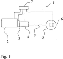
- Figure 1 schematically discloses a drive train 1 of a vehicle with braking device 6, which in the shown example is arranged to brake driven wheel 5 of the vehicle.
- Said wheel 5 is driven by a propulsion unit 2 via a stagegeared automatic transmission 3, 4 and a propeller shaft 8 in a known way.
- the automatic transmission can comprise of; a clutch 3 and an automated manual transmission (AMT) 4, or a double clutch transmission (DCT) 3 and 4, or a torque converter 3 and an automatic gearbox 4.
- AMT automated manual transmission
- DCT double clutch transmission
- Said propulsion unit can be a combustion engine or a combination of a combustion engine and an electric motor/generator, so called hybrid electric vehicle (HEV).
- HEV hybrid electric vehicle
- the braking device 6 is in the shown example disclosed as a service brake, which for example can be controlled by the driver of the vehicle through a brake pedal (not shown) in a known way.
- a service brake which for example can be controlled by the driver of the vehicle through a brake pedal (not shown) in a known way.
- other braking devices in the vehicle in combination with the service brake or instead of said service brake, such as auxiliary brakes or electric brakes (for example said motor/generator) to stop the vehicle.
- a control unit 7 can be arranged to control the propulsion unit 2 and its torque output, the automatic transmission 3, 4 and the braking device 6 in accordance with different input signals such as rotational speeds of propulsion unit, rotational speeds of input/output shaft of said transmission, selected gear in the transmission and driver input through for example an accelerator pedal and a brake pedal in a known way.
- Said control unit can in an alternative embodiment comprise of two or several control units connected for example through a network. Said controlling functions according to the invention can be divided between said control units.
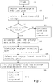
- the control unit 7 is programmed to select and engage a first vehicle starting gear at vehicle stand still and said transmission being disengaged from the propulsion unit 2. See S2 in flow chart in figure 2 , where the control sequence starts in S1.
- a starting gear can for example be automatically selected and engaged if the driver has chosen an automatic mode through a gear shift lever (not shown). It can also be possible for the driver to make a manual selection of the starting gear, even though the engagement as such of the gear is performed by the control unit.
- the meaning of the transmission 3, 4 being disengaged from the propulsion unit can for example be a disengaged clutch 3, arranged between the propulsion unit and a stagegeared transmission (DCT or AMT with a clutch) or a torque converter empty of oil, meaning that the torque converter will not transmit any torque from the propulsion unit to the stagegeared transmission.
- the control unit 7 is further programmed to, on driver demand for example through the accelerator pedal, control vehicle propulsive torque produced by said propulsion unit and engagement of said transmission to the propulsion unit in such a way as to attempt to achieve a first vehicle take off (S3 in figure 2 ). The take off attempt as such is performed in a known way.
- the propulsion unit is gradually engaged with the transmission and more and more torque delivered by the propulsion unit is transmitted to the driven wheel.
- the transmission comprises of a lamella type clutch, such as in an AMT with an automated clutch or a DCT.
- a measure of this wear can be to calculate heat energy created during clutch slip. This can be done by taking the torque and multiply with the rotational speed difference over the clutch and integrate the multiplied sum over time. If the calculated heat created during the clutch slip of the first vehicle take off is over a predetermined value the control unit is according to the invention programmed to detect this as said first starting gear being a to high starting gear (S4 and "Yes" in figure 2 ). Thus, the first starting gear is wrongly selected for the prevailing vehicle starting situation. If the starting gear is not too high then the control unit is programmed to complete the take off attempt (S5 and "No" in figure 2 ).
- the control unit 7 will then automatically interrupt (S6) the first vehicle take off and brake the vehicle by activating said braking device and then disengaging (S7) said first vehicle starting gear.
- the braking device When the braking device is activated the vehicle is stopped and/or hindered from rolling in the opposite travel direction compared to the selected travel direction, for example when starting in an uphill.
- the control unit When the first starting gear is disengaged the control unit is programmed to select and engage a second vehicle starting gear which is a lower gear compared to said first starting gear (S8), thus this second starting gear has a higher gear ratio compared to the first starting gear.
- the control unit can be programmed to directly select the lowest possible starting gear after a first interrupted take off attempt.
- control unit When the second starting gear is engaged the control unit is programmed to start a second vehicle take off attempt (S9) by controlling propulsive torque produced by said propulsion unit and engagement of said transmission in such a way as to achieve a second vehicle take off.
- S9 a second vehicle take off attempt
- the sequence in figure 2 is ended by the completion of the second take off attempt with the lowest possible starting gear.
- the first vehicle take off attempt was initiated by the driver maneuvering, for example an accelerator pedal, and demanding a certain torque output from the propulsion unit.
- This driver input tells the control unit to control the propulsion unit and the clutch (or torque converter) in a predetermined way.
- the driver has the possibility to continue demanding the same torque output before the second take off attempt, thus the driver can continue demanding the same torque output during said both take off attempts.
- the control unit is according to the invention programmed to inactivate said braking device 6 (see also S9).
- the inactivation of the braking device can be done gradually in a predefined controlled way and follow the gradual increase of transmitted torque to the driven wheel.
- Said controlled inactivation of the braking device is known as such.
- the clutch wear can be measured by calculating heat energy and compared to a predetermined value. If the calculated heat energy value is below the predetermined value and the transmission of torque to the driven wheel 5 is enough as to keep the vehicle at least in stand still and the braking device 6 has been inactivated, then said control unit is programmed to continue to engage the clutch until it is fully engaged and the vehicle will take off.
- step S31 to S39 correspond to steps S1 to S9 in figure 2 .
- step S310 in figure 3 the control unit is programmed to detect if the second starting gear also is too high or not. If not the take off attempt continues in S311 until completed, if yes then the control unit is programmed to go back to step S36 and interrupt the take off attempt and prepare for another take off attempt with an even lower starting gear.
- control unit can be programmed to interpret how bad the first take off attempt was and as a result select an adapted lower second starting gear. For example if the first take off attempt is performed with gear three, the control unit can choose between gear two or gear one before the second take off attempt. The choice between the mentioned starting gears can be decided by the control unit being programmed to again calculate heat energy during the clutch slip and as further information also register the rotational speed of an input shaft of the gearbox in the transmission. In this way the control unit can assess how close to success this take off attempt was. If the rotational speed of the input shaft was relatively low then gear one (in this case the same as the lowest possible) will be selected as the new starting gear. If the rotational speed of the input shaft was relatively high then gear two will be selected as the next starting gear.
- a further input that can be considered by the control unit 7 in all mentioned embodiments of the invention can be the rotational speed of the propulsion unit, that is, the rotational speed decides which torque output that is available from the propulsion unit in order to be able to transmit a certain amount of torque to the drive wheels to be able to reach a successful vehicle take off.
- the step S3 of detecting that said first vehicle take off is not possible with said first starting gear can be detected by the driver instead.
- the driver can interrupt the take off attempt by, for example, directly select another starting gear through a gear shift lever.
- the driver can choose the lowest possible gear (corresponding to step S8) or just select a lower gear than the first starting gear (corresponding to step S38). This manual interruption and starting gear selection initiates the control unit 7 to automatically perform steps corresponding to steps S6 to S10.
- control unit can be programmed to warn the driver.
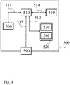
- Figure 4 shows an apparatus 500 according to one embodiment of the invention, comprising a nonvolatile memory 520, a processor 510 and a read and write memory 560.
- the memory 520 has a first memory part 530, in which a computer program for controlling the apparatus 500 is stored.
- the computer program in the memory part 530 for controlling the apparatus 500 can be an operating system.
- the apparatus 500 can be enclosed in, for example, a control unit, such as the control unit 7.
- the data-processing unit 510 can comprise, for example, a microcomputer.
- the memory 520 also has a second memory part 540, in which a program for controlling the engine, the clutch, the transmission and the braking device according to the invention is stored.
- the program with functions according to the invention is stored in a separate nonvolatile data storage medium 550, such as, for example, a CD or an exchangeable semiconductor memory.
- the program can be stored in an executable form or in a compressed state.
- the data-processing unit 510 runs a specific function, it should be clear that the data-processing unit 510 is running a specific part of the program stored in the memory 540 or a specific part of the program stored in the nonvolatile recording medium 550.
- the data-processing unit 510 is tailored for communication with the memory 550 through a data bus 514.
- the data-processing unit 510 is also tailored for communication with the memory 520 through a data bus 512.
- the data-processing unit 510 is tailored for communication with the memory 560 through a data bus 511.
- the data-processing unit 510 is also tailored for communication with a data port 590 by the use of a data bus 515.
- the method according to the present invention can be executed by the data-processing unit 510, by the data-processing unit 510 running the program stored in the memory 540 or the program stored in the nonvolatile recording medium 550.
Landscapes
- Engineering & Computer Science (AREA)
- Mechanical Engineering (AREA)
- General Engineering & Computer Science (AREA)
- Transportation (AREA)
- Control Of Transmission Device (AREA)
- Regulating Braking Force (AREA)
Description
- The present invention relates to a method for automatic or semiautomatic selection of a better starting gear in a vehicle according to the
claim 1 below.
The invention also relates to a vehicle comprising a control unit arranged to perform steps for automatic or semiautomatic selection of a better starting gear according to theclaim 6.
The invention also relates to a computer program and computer program products for carrying out said method. -
WO02/42108A1 - selecting and engaging a first vehicle starting gear at vehicle stand still
- on driver demand controlling vehicle propulsion torque by gradually engaging a propulsion unit to driven wheels of the vehicle as to attempt to achieve a first vehicle take off
- detecting if said first vehicle starting gear is too high for a prevailing condition of the first vehicle take off
- disengaging said first vehicle starting gear
- selecting and engaging an adapted second starting gear which is a lower gear compared to said first starting gear and having a higher gear ratio -controlling vehicle propulsion torque by gradually engaging said propulsion unit to said driven wheels as to attempt to achieve a second vehicle take off.
- A gearbox of the AMT-type usually comprises an input shaft, an intermediate shaft, which has at least one toothed gear meshing with a toothed gear on the input shaft, and main shaft with toothed gears, which mesh with toothed gears on the intermediate shaft. The main shaft is then further connected to an output shaft coupled to the driving wheels via a propeller shaft, for example. Each pair of toothed gears has a different gear ratio from another pair of gears in the gearbox.
- Different transmission ratios are obtained in that different pairs of gears transmit the torque from the engine to the driving wheels.
- The development of computer technology has also had an impact on electronic control and feedback systems for a vehicle engine, and these systems have become more precise, faster and more adaptable to prevailing engine and environmental conditions. The entire combustion process can be precisely controlled according to any operating situation. The vehicle's throttle lever (an accelerator pedal, for example), which primarily controls the fuel supply to the engine, controls the vehicle's engine via electrical wiring and electronic signals. The throttle lever is therefore equipped with sensors for detecting the throttle lever position, that is to say what throttle opening is required.
- In the process of vehicle take off an automatic disc clutch as described above is included in the AMT and is usually controlled by means of information on the position of the throttle lever, the rotational speed of the engine, the engine output torque, the position of the disc clutch and from a reference position of the disc clutch, which is selected on the basis of when the disc clutch just begins to transmit torque (traction position), this position being relatively easy to define. A torque typically transmitted in the reference position may be in the order of 30 Nm. The engine output torque is mostly calculated from the quantity of fuel injected into the engine. In the starting sequence and maneuvering the vehicle is typically started from stationary or a virtually stationary state, and the engine commences the sequence at idling speed. The position of the disc clutch and hence the degree of engagement, which determines the torque transmitted from the engine to the gearbox, primarily depends on where the driver positions the throttle lever. The reference position of the disc clutch is used to give the driver of the vehicle more accurate control of the vehicle take off in that the disc clutch assumes the reference position immediately a starting gear is selected and engaged. The vehicle is prepared for immediate take off. Thus in many situations the driver experiences only a small flat spot, if any, when the accelerator pedal is depressed. The driver therefore obtains a theoretically direct response and the vehicle in principle starts to move as soon as the accelerator pedal starts to be depressed.
- The selection of an appropriate starting gear in an AMT is normally based on a calculation from at least parameters such as road inclination and vehicle weight. Even though this calculation covers a lot of vehicle starting situations a selected starting gear will sometimes not become right due to a changed vehicle condition, which the calculation cannot foresee. One such situation can be when a long-distance truck has been parked with the truck on a horizontal part of the road and the trailer in a down slope. From a starting gear selection point of view this situation can get even worse if the trailer and truck when parked are empty and then the trailer is loaded before a take-off. Such a calculation will probably not take into account the weight change of the trailer and that it is parked in a down slope. This will most likely make the AMT to select a too high starting gear and an unsuccessful vehicle take off is most likely to happen due to the weight increase of the trailer and in that the trailer is parked in a down slope that counteracts propulsive power. The driver will have to interrupt an unsuccessful take off attempt and hinder the truck from rolling backwards by, for example, activating the service brakes. Then a more proper starting gear will have to be selected manually since the AMT control unit will not know about the changed condition.
- There is therefore a need to make it easier for the driver to handle such take offs as mentioned above. This is the primary object of the invention described below.
- The means of achieving the object of the invention in respect of the method according to the invention are described in
claim 1 and the device inclaim 6. The other claims describe embodiments and developments of the method according to the invention (claims 2 to 5). - The method according to the invention describes a method for automatic or semiautomatic selection of a better starting gear in a vehicle. The method is characterized by the following steps executed in mentioned order:
- selecting and engaging a first vehicle starting gear at vehicle stand still,
- on driver demand controlling vehicle propulsion torque in such a way as to attempt to achieve a first vehicle take off,
- detecting if said first vehicle starting gear is to high for a prevailing condition of the first vehicle take off,
- if the first vehicle starting gear is too high then interrupting the first vehicle take off and braking the vehicle,
- disengaging said first vehicle starting gear,
- selecting and engaging a second starting gear which is a lower gear compared to said first starting gear and having a higher gear ratio,
- controlling vehicle propulsion torque in such a way as to attempt to achieve a second vehicle take off,
- and if said second vehicle take off attempt results in a transmitting of torque to driven wheels of the vehicle being enough as to perform a take off then stop braking the vehicle.
- The advantage of the method according to the invention is that a wrongly selected starting gear is automatically or semi automatically changed. A further advantage is that the starting gear change can be performed in an uphill situation. Thus, it will be possible to change the wrongly selected starting gear without risking that the vehicle is rolling off in the wrong direction.
- According to an advantageous second embodiment of the method according to the invention the step of detecting that said first vehicle take off is not possible with said first starting gear is done by calculating heat energy developed in the clutch during the first vehicle take off attempt and interrupting said first vehicle take off attempt if said heat energy exceeds a predetermined heat energy limit. This is an advantageous way of detecting if a starting gear was wrongly selected.
- According to an advantageous further embodiment of the method according to the invention the step of detecting that said first vehicle take off is not possible with said first starting gear can be done by the driver. The subsequent step of interrupting the first vehicle take off can be performed manually by the driver. This gives increased operational freedom to the driver. The step of interrupting the first vehicle take off can be performed by the driver manually selecting a lower gear by, for example, operating a gear shift lever.
- According to an advantageous further embodiment of the method according to the invention if said second take off attempt results in transmission of torque to the driven wheels enough to keep the vehicle at least in stand still, then continuing controlling clutch engagement of a clutch until the clutch is fully engaged and the vehicle takes off. This point in the engagement is a further indication of a successful starting gear selection and clutch engagement process.
- Further advantageous embodiments of the invention are set forth in the succeeding dependent claims.
- The present invention will be described in more detail below with reference to the drawings attached, which by way of example show further preferred embodiments of the invention.
-
Figure 1 shows a schematic diagram of an embodiment of a device for achieving the objects of the invention. -
Figure 2 and3 show two different flow charts disclosing the different steps of two different embodiments of the invention.Figure 4 shows diagrammatically a computer device that is used according to an embodiment of the invention. -
Figure 1 schematically discloses adrive train 1 of a vehicle withbraking device 6, which in the shown example is arranged to brake drivenwheel 5 of the vehicle.Said wheel 5 is driven by apropulsion unit 2 via a stagegearedautomatic transmission clutch 3 and an automated manual transmission (AMT) 4, or a double clutch transmission (DCT) 3 and 4, or atorque converter 3 and anautomatic gearbox 4. Said propulsion unit can be a combustion engine or a combination of a combustion engine and an electric motor/generator, so called hybrid electric vehicle (HEV). Thebraking device 6 is in the shown example disclosed as a service brake, which for example can be controlled by the driver of the vehicle through a brake pedal (not shown) in a known way. For the invention it is also possible to use other braking devices in the vehicle in combination with the service brake or instead of said service brake, such as auxiliary brakes or electric brakes (for example said motor/generator) to stop the vehicle. - A
control unit 7 can be arranged to control thepropulsion unit 2 and its torque output, theautomatic transmission braking device 6 in accordance with different input signals such as rotational speeds of propulsion unit, rotational speeds of input/output shaft of said transmission, selected gear in the transmission and driver input through for example an accelerator pedal and a brake pedal in a known way. Said control unit can in an alternative embodiment comprise of two or several control units connected for example through a network. Said controlling functions according to the invention can be divided between said control units. - According to one embodiment of the invention, the
control unit 7 is programmed to select and engage a first vehicle starting gear at vehicle stand still and said transmission being disengaged from thepropulsion unit 2. See S2 in flow chart infigure 2 , where the control sequence starts in S1. A starting gear can for example be automatically selected and engaged if the driver has chosen an automatic mode through a gear shift lever (not shown). It can also be possible for the driver to make a manual selection of the starting gear, even though the engagement as such of the gear is performed by the control unit. The meaning of thetransmission disengaged clutch 3, arranged between the propulsion unit and a stagegeared transmission (DCT or AMT with a clutch) or a torque converter empty of oil, meaning that the torque converter will not transmit any torque from the propulsion unit to the stagegeared transmission. Thecontrol unit 7 is further programmed to, on driver demand for example through the accelerator pedal, control vehicle propulsive torque produced by said propulsion unit and engagement of said transmission to the propulsion unit in such a way as to attempt to achieve a first vehicle take off (S3 infigure 2 ). The take off attempt as such is performed in a known way. Thus, the propulsion unit is gradually engaged with the transmission and more and more torque delivered by the propulsion unit is transmitted to the driven wheel. If the first starting gear is too high, that is, the gear ratio is to low, there will be excessive clutch wear if the transmission comprises of a lamella type clutch, such as in an AMT with an automated clutch or a DCT. A measure of this wear can be to calculate heat energy created during clutch slip. This can be done by taking the torque and multiply with the rotational speed difference over the clutch and integrate the multiplied sum over time. If the calculated heat created during the clutch slip of the first vehicle take off is over a predetermined value the control unit is according to the invention programmed to detect this as said first starting gear being a to high starting gear (S4 and "Yes" infigure 2 ). Thus, the first starting gear is wrongly selected for the prevailing vehicle starting situation. If the starting gear is not too high then the control unit is programmed to complete the take off attempt (S5 and "No" infigure 2 ). - If the starting gear is too high, the
control unit 7 will then automatically interrupt (S6) the first vehicle take off and brake the vehicle by activating said braking device and then disengaging (S7) said first vehicle starting gear. When the braking device is activated the vehicle is stopped and/or hindered from rolling in the opposite travel direction compared to the selected travel direction, for example when starting in an uphill. When the first starting gear is disengaged the control unit is programmed to select and engage a second vehicle starting gear which is a lower gear compared to said first starting gear (S8), thus this second starting gear has a higher gear ratio compared to the first starting gear. In one embodiment of the invention the control unit can be programmed to directly select the lowest possible starting gear after a first interrupted take off attempt. When the second starting gear is engaged the control unit is programmed to start a second vehicle take off attempt (S9) by controlling propulsive torque produced by said propulsion unit and engagement of said transmission in such a way as to achieve a second vehicle take off. The sequence infigure 2 is ended by the completion of the second take off attempt with the lowest possible starting gear. - The first vehicle take off attempt was initiated by the driver maneuvering, for example an accelerator pedal, and demanding a certain torque output from the propulsion unit. This driver input tells the control unit to control the propulsion unit and the clutch (or torque converter) in a predetermined way. The driver has the possibility to continue demanding the same torque output before the second take off attempt, thus the driver can continue demanding the same torque output during said both take off attempts. If said second vehicle take off attempt results in a transmission of torque to the driven
wheel 5 enough to perform a take off then the control unit is according to the invention programmed to inactivate said braking device 6 (see also S9). The inactivation of the braking device can be done gradually in a predefined controlled way and follow the gradual increase of transmitted torque to the driven wheel. Said controlled inactivation of the braking device is known as such. Also during the second take off attempt the clutch wear can be measured by calculating heat energy and compared to a predetermined value. If the calculated heat energy value is below the predetermined value and the transmission of torque to the drivenwheel 5 is enough as to keep the vehicle at least in stand still and thebraking device 6 has been inactivated, then said control unit is programmed to continue to engage the clutch until it is fully engaged and the vehicle will take off. - In one alterative embodiment of the invention disclosed in
figure 3 the above starting process can be repeated until the lowest gear has been selected and tried for take off. Thus, the starting gear can be lowered one gear step at a time. Infigure 3 step S31 to S39 correspond to steps S1 to S9 infigure 2 . One difference is that in the sequence offigure 3 in step S38 not the lowest possible starting gear is selected but instead the next lower starting gear. In step S310 infigure 3 the control unit is programmed to detect if the second starting gear also is too high or not. If not the take off attempt continues in S311 until completed, if yes then the control unit is programmed to go back to step S36 and interrupt the take off attempt and prepare for another take off attempt with an even lower starting gear. - In a further embodiment of the invention the control unit can be programmed to interpret how bad the first take off attempt was and as a result select an adapted lower second starting gear. For example if the first take off attempt is performed with gear three, the control unit can choose between gear two or gear one before the second take off attempt. The choice between the mentioned starting gears can be decided by the control unit being programmed to again calculate heat energy during the clutch slip and as further information also register the rotational speed of an input shaft of the gearbox in the transmission. In this way the control unit can assess how close to success this take off attempt was. If the rotational speed of the input shaft was relatively low then gear one (in this case the same as the lowest possible) will be selected as the new starting gear. If the rotational speed of the input shaft was relatively high then gear two will be selected as the next starting gear.
- A further input that can be considered by the
control unit 7 in all mentioned embodiments of the invention can be the rotational speed of the propulsion unit, that is, the rotational speed decides which torque output that is available from the propulsion unit in order to be able to transmit a certain amount of torque to the drive wheels to be able to reach a successful vehicle take off. - In an alternative embodiment of the invention according to
figure 2 the step S3 of detecting that said first vehicle take off is not possible with said first starting gear can be detected by the driver instead. Thus, if the driver notices that the selected and engaged starting gear is too high the driver can interrupt the take off attempt by, for example, directly select another starting gear through a gear shift lever. The driver can choose the lowest possible gear (corresponding to step S8) or just select a lower gear than the first starting gear (corresponding to step S38). This manual interruption and starting gear selection initiates thecontrol unit 7 to automatically perform steps corresponding to steps S6 to S10. - In a further embodiment it is possible for the driver to change the selected starting gear before the take off attempt has even started, that is, before the driver requesting take off for example by pressing the accelerator pedal. Such an embodiment will thus upon manual selection of a lower second starting gear automatically initiate the
control unit 7 to perform steps corresponding to steps S6 to S10. - The mentioned two semiautomatic driver initiated embodiments of the invention can be combined with each other or with the above described fully automatic embodiments of the invention for selecting a better starting gear.
- Of coarse there can be embodiments of the invention where a vehicle only has functionality according to the above described fully automatic embodiments of selecting a better starting gear.
- In all the above mentioned embodiments, if the lowest gear is not possible to start with without risking severe transmission wear the control unit can be programmed to warn the driver.
-
Figure 4 shows anapparatus 500 according to one embodiment of the invention, comprising anonvolatile memory 520, aprocessor 510 and a read and writememory 560. Thememory 520 has afirst memory part 530, in which a computer program for controlling theapparatus 500 is stored. The computer program in thememory part 530 for controlling theapparatus 500 can be an operating system. Theapparatus 500 can be enclosed in, for example, a control unit, such as thecontrol unit 7. The data-processing unit 510 can comprise, for example, a microcomputer. - The
memory 520 also has asecond memory part 540, in which a program for controlling the engine, the clutch, the transmission and the braking device according to the invention is stored. In an alternative embodiment, the program with functions according to the invention is stored in a separate nonvolatiledata storage medium 550, such as, for example, a CD or an exchangeable semiconductor memory. The program can be stored in an executable form or in a compressed state. - When it is stated below that the data-
processing unit 510 runs a specific function, it should be clear that the data-processing unit 510 is running a specific part of the program stored in thememory 540 or a specific part of the program stored in thenonvolatile recording medium 550. - The data-
processing unit 510 is tailored for communication with thememory 550 through adata bus 514. The data-processing unit 510 is also tailored for communication with thememory 520 through adata bus 512. In addition, the data-processing unit 510 is tailored for communication with thememory 560 through adata bus 511. The data-processing unit 510 is also tailored for communication with adata port 590 by the use of adata bus 515. - The method according to the present invention can be executed by the data-
processing unit 510, by the data-processing unit 510 running the program stored in thememory 540 or the program stored in thenonvolatile recording medium 550. - The invention should not be deemed to be limited to the embodiments described above, but rather a number of further variants and modifications are conceivable within the scope of the following patent claims.
Claims (9)
- A method for automatic or semiautomatic selection of a better starting gear in a vehicle, comprising the following steps executed in mentioned order:- selecting and engaging a first vehicle starting gear at vehicle stand still (S2, S32),- on driver demand controlling vehicle propulsion torque in such a way as to attempt to achieve a first vehicle take off (S3, S33),- detecting if said first vehicle starting gear is too high for a prevailing condition of the first vehicle take off (S4, S34),- if the first vehicle starting gear is too high then interrupting the first vehicle take off and braking the vehicle (S6, S36),- disengaging said first vehicle starting gear (S7, S37),- selecting and engaging a second starting gear which is a lower gear compared to said first starting gear and having a higher gear ratio (S8, S38),- controlling vehicle propulsion torque in such a way as to attempt to achieve a second vehicle take off,- and if said second vehicle take off attempt results in a transmitting of torque to driven wheels of the vehicle being enough as to perform a take off then stop braking the vehicle (S9, S39) .
- The method as claimed in the preceding claim, characterized in that the step of detecting that said first vehicle take off is not possible with said first starting gear is done by calculating heat energy developed in the clutch during the first vehicle take off attempt and interrupting said first vehicle take off attempt if said heat energy exceeds a predetermined heat energy limit.
- The method as claimed in claim 1, characterized in that the step of detecting that said first vehicle take off is not possible with said first starting gear is done by the driver and in that the subsequent step of interrupting the first vehicle take off is performed manually by the driver.
- The method as claimed in the preceding claim, characterized in that the step of interrupting the first vehicle take off is performed by the driver manually selecting a lower gear.
- The method as claimed in one of the preceding claims, characterized in that if said second take off attempt results in transmission of torque to the driven wheels enough to keep the vehicle at least in stand still, then continuing controlling clutch engagement of a clutch until the clutch is fully engaged and the vehicle takes off (S10, S310) .
- A vehicle comprising a propulsion unit (2) drivingly connected to a stage geared automatic transmission (3, 4), which is drivingly connected to driven wheels (5) of the vehicle, a braking device (6) arranged to be able to stop the vehicle, at least a control unit (7) arranged to control said propulsion unit, said automatic transmission and said braking device in dependence of different input signals, said control unit (7) is arranged to execute the following steps in mentioned order:- select and engage a first vehicle starting gear at vehicle stand still and when said transmission is disengaged from said propulsion unit (S2, S32),- on driver demand control vehicle propulsive torque produced by said propulsion unit and engagement of said transmission to said propulsion unit in such a way as to attempt to achieve a first vehicle take off (S3, S33),- detect if said first vehicle starting gear is too high for a prevailing condition of the first vehicle take off (S4, S34),- if the first vehicle starting gear is too high then interrupt the first vehicle take off and braking the vehicle by activation of said braking device (S6, S36),- disengage said first vehicle starting gear (S7, S37),- select and engage a second vehicle starting gear which is a lower gear compared to said first starting gear and which has a higher gear ratio (S8, S38),- control vehicle propulsive torque produced by said propulsion unit and engagement of said transmission in such a way as to attempt to achieve a second vehicle take off,- if said second vehicle take off attempt results in a transmission of torque to the driven wheels enough to perform a take off then inactivate said braking device (S9, S39).
- A computer program comprising a program code for executing the method as claimed in claim 1, when said computer program is executed on a computer.
- A computer program product comprising a program code, stored on a computer-readable medium, for executing the method as claimed in claim 1, when said computer program is executed on the computer.
- A computer program product directly loadable into an internal memory in a computer, which computer program product comprises a computer program for executing the method as claimed in claim 1, when said computer program on the computer program product is executed on the computer.
Applications Claiming Priority (1)
| Application Number | Priority Date | Filing Date | Title |
|---|---|---|---|
| PCT/SE2008/000165 WO2009108087A1 (en) | 2008-02-28 | 2008-02-28 | A method and device for automatic or semiautomatic selection of a better starting gear in a vehicle |
Publications (3)
| Publication Number | Publication Date |
|---|---|
| EP2257722A1 EP2257722A1 (en) | 2010-12-08 |
| EP2257722A4 EP2257722A4 (en) | 2018-04-18 |
| EP2257722B1 true EP2257722B1 (en) | 2019-01-02 |
Family
ID=41016319
Family Applications (1)
| Application Number | Title | Priority Date | Filing Date |
|---|---|---|---|
| EP08712749.4A Revoked EP2257722B1 (en) | 2008-02-28 | 2008-02-28 | A method and device for automatic or semiautomatic selection of a better starting gear in a vehicle |
Country Status (6)
| Country | Link |
|---|---|
| US (1) | US8401750B2 (en) |
| EP (1) | EP2257722B1 (en) |
| JP (1) | JP5254366B2 (en) |
| CN (1) | CN101952621B (en) |
| BR (1) | BRPI0822301B1 (en) |
| WO (1) | WO2009108087A1 (en) |
Families Citing this family (16)
| Publication number | Priority date | Publication date | Assignee | Title |
|---|---|---|---|---|
| CN102132075B (en) * | 2008-08-28 | 2014-10-29 | 沃尔沃拉斯特瓦格纳公司 | Method and vehicle transmission for selecting a starting gear in a vehicle |
| SE534650C2 (en) * | 2010-02-01 | 2011-11-08 | Scania Cv Ab | Procedure and system for controlling a gearbox |
| DE102010028282A1 (en) * | 2010-04-28 | 2011-12-01 | Zf Friedrichshafen Ag | Method for determining a starting gear in a motor vehicle |
| CN103121450B (en) * | 2011-11-18 | 2016-08-24 | 北汽福田汽车股份有限公司 | A kind of ramp way control method of pure electric automobile |
| CN103386967B (en) * | 2012-05-08 | 2016-01-13 | 上海捷能汽车技术有限公司 | For control method and the power system of automatic transmission with hydraulic torque converter |
| JP6401253B2 (en) | 2013-10-02 | 2018-10-10 | ボルボトラックコーポレーション | Method and apparatus for adjusting starter gear of vehicle |
| DE102015005850A1 (en) * | 2015-05-06 | 2016-11-10 | GM Global Technology Operations LLC (n. d. Ges. d. Staates Delaware) | Method for operating a motor vehicle |
| SE540141C2 (en) | 2016-03-23 | 2018-04-10 | Scania Cv Ab | A method of operating a hybrid driveline, a hybrid driveline and a vehicle, comprising such a hybrid driveline |
| WO2017195070A1 (en) | 2016-05-09 | 2017-11-16 | 3M Innovative Properties Company | Hydrofluoroolefins and methods of using same |
| US11021161B2 (en) | 2016-07-19 | 2021-06-01 | Volvo Truck Corporation | Method and arrangement for determining road inclination |
| CN106882180B (en) * | 2017-01-09 | 2019-02-12 | 北京理工大学 | A starting control method for an unmanned tracked vehicle |
| CN111742166B (en) * | 2018-05-14 | 2022-07-22 | 舍弗勒技术股份两合公司 | Shift control method for automatic transmission, shift control device for automatic transmission, and vehicle power system |
| CN110553031A (en) * | 2019-09-27 | 2019-12-10 | 南京汽车集团有限公司 | starting gear selection and control method for light truck AMT (automated mechanical Transmission) |
| CN112728069B (en) * | 2020-12-25 | 2022-07-08 | 采埃孚商用车系统(青岛)有限公司 | Method and system for selecting proper starting gear |
| CN114475277A (en) * | 2022-03-11 | 2022-05-13 | 东风汽车集团股份有限公司 | Analysis method for automatic gear shifting and economic speed per hour of driving |
| CN116572959A (en) * | 2023-06-19 | 2023-08-11 | 一汽解放汽车有限公司 | A vehicle starting method, device, electronic equipment and storage medium |
Citations (12)
| Publication number | Priority date | Publication date | Assignee | Title |
|---|---|---|---|---|
| CN1089906A (en) | 1992-08-27 | 1994-07-27 | 易通公司 | Start ratio engagement control system and method |
| DE19602006A1 (en) | 1995-01-28 | 1996-08-01 | Luk Getriebe Systeme Gmbh | Device and a method for controlling a torque transmission system |
| CN1215670A (en) | 1997-02-01 | 1999-05-05 | 易通公司 | Start ratio selection for vehicular automated transmissions |
| DE19839837A1 (en) | 1998-09-02 | 2000-03-09 | Zahnradfabrik Friedrichshafen | Procedure for determining a starting gear |
| WO2002042108A1 (en) | 2000-11-21 | 2002-05-30 | Eaton Corporation | Starting and driveline shock protection control method and system |
| US20040025617A1 (en) | 2000-07-26 | 2004-02-12 | Fowler Martin Stanley | Automatic selection of start gear |
| WO2004058551A1 (en) | 2002-12-30 | 2004-07-15 | Volvo Lastvagnar Ab | Method and device for hill start |
| DE102004023581A1 (en) | 2004-05-13 | 2005-12-08 | Adam Opel Ag | Clutch controlling method for motor vehicle gear, involves evaluating temperature of clutch and comparing temperature with temperature threshold value, where control unit is substitution strategy for starting vehicle |
| DE102005029566A1 (en) | 2004-06-30 | 2006-02-02 | Luk Lamellen Und Kupplungsbau Beteiligungs Kg | Method for protection of automatically actuated clutch of vehicle from overload, involves preventing overload state of clutch through targeted intervention in vehicle management as function of driving situation and energy input in clutch |
| US20060079373A1 (en) | 2004-10-12 | 2006-04-13 | Honda Motor Co., Ltd. | Control device for hydraulic automatic transmission for vehicle |
| WO2007030057A1 (en) | 2005-09-08 | 2007-03-15 | Volvo Lastvagnar Ab | A method for adapting gear selection in a vehicle |
| JP2007132364A (en) | 2005-11-08 | 2007-05-31 | Hino Motors Ltd | Starting gear selection alarm device |
Family Cites Families (4)
| Publication number | Priority date | Publication date | Assignee | Title |
|---|---|---|---|---|
| JPS636259A (en) * | 1986-06-26 | 1988-01-12 | Isuzu Motors Ltd | Electronic control automatic transmission |
| JPS6343829A (en) * | 1986-08-12 | 1988-02-24 | Isuzu Motors Ltd | Starting gear selector for electronically controlled automatic transmission |
| JP2005048893A (en) * | 2003-07-30 | 2005-02-24 | Nissan Diesel Motor Co Ltd | Clutch control device |
| JP2006001338A (en) * | 2004-06-16 | 2006-01-05 | Hitachi Ltd | Control device, control method and vehicle for vehicle with automatic clutch |
-
2008
- 2008-02-28 WO PCT/SE2008/000165 patent/WO2009108087A1/en not_active Ceased
- 2008-02-28 BR BRPI0822301-7A patent/BRPI0822301B1/en active IP Right Grant
- 2008-02-28 US US12/919,824 patent/US8401750B2/en active Active
- 2008-02-28 JP JP2010548637A patent/JP5254366B2/en active Active
- 2008-02-28 CN CN200880127347.5A patent/CN101952621B/en active Active
- 2008-02-28 EP EP08712749.4A patent/EP2257722B1/en not_active Revoked
Patent Citations (15)
| Publication number | Priority date | Publication date | Assignee | Title |
|---|---|---|---|---|
| CN1089906A (en) | 1992-08-27 | 1994-07-27 | 易通公司 | Start ratio engagement control system and method |
| DE19602006A1 (en) | 1995-01-28 | 1996-08-01 | Luk Getriebe Systeme Gmbh | Device and a method for controlling a torque transmission system |
| US5823912A (en) | 1995-01-28 | 1998-10-20 | Luk Getriebe-Systeme Gmbh | Method and apparatus for detecting friction heat of a clutch and regulating the clutch |
| CN1215670A (en) | 1997-02-01 | 1999-05-05 | 易通公司 | Start ratio selection for vehicular automated transmissions |
| DE19839837A1 (en) | 1998-09-02 | 2000-03-09 | Zahnradfabrik Friedrichshafen | Procedure for determining a starting gear |
| US20040025617A1 (en) | 2000-07-26 | 2004-02-12 | Fowler Martin Stanley | Automatic selection of start gear |
| US6953410B2 (en) | 2000-07-26 | 2005-10-11 | Eaton Corporation | Automatic selection of start gear |
| WO2002042108A1 (en) | 2000-11-21 | 2002-05-30 | Eaton Corporation | Starting and driveline shock protection control method and system |
| WO2004058551A1 (en) | 2002-12-30 | 2004-07-15 | Volvo Lastvagnar Ab | Method and device for hill start |
| US20060079377A1 (en) | 2002-12-30 | 2006-04-13 | Volvo Lastvagnar Ab | Method and device for hill start |
| DE102004023581A1 (en) | 2004-05-13 | 2005-12-08 | Adam Opel Ag | Clutch controlling method for motor vehicle gear, involves evaluating temperature of clutch and comparing temperature with temperature threshold value, where control unit is substitution strategy for starting vehicle |
| DE102005029566A1 (en) | 2004-06-30 | 2006-02-02 | Luk Lamellen Und Kupplungsbau Beteiligungs Kg | Method for protection of automatically actuated clutch of vehicle from overload, involves preventing overload state of clutch through targeted intervention in vehicle management as function of driving situation and energy input in clutch |
| US20060079373A1 (en) | 2004-10-12 | 2006-04-13 | Honda Motor Co., Ltd. | Control device for hydraulic automatic transmission for vehicle |
| WO2007030057A1 (en) | 2005-09-08 | 2007-03-15 | Volvo Lastvagnar Ab | A method for adapting gear selection in a vehicle |
| JP2007132364A (en) | 2005-11-08 | 2007-05-31 | Hino Motors Ltd | Starting gear selection alarm device |
Also Published As
| Publication number | Publication date |
|---|---|
| EP2257722A4 (en) | 2018-04-18 |
| EP2257722A1 (en) | 2010-12-08 |
| WO2009108087A1 (en) | 2009-09-03 |
| BRPI0822301A2 (en) | 2020-08-11 |
| CN101952621B (en) | 2014-05-07 |
| BRPI0822301B1 (en) | 2021-02-17 |
| JP2011518064A (en) | 2011-06-23 |
| US20110010060A1 (en) | 2011-01-13 |
| CN101952621A (en) | 2011-01-19 |
| JP5254366B2 (en) | 2013-08-07 |
| US8401750B2 (en) | 2013-03-19 |
Similar Documents
| Publication | Publication Date | Title |
|---|---|---|
| EP2257722B1 (en) | A method and device for automatic or semiautomatic selection of a better starting gear in a vehicle | |
| EP2148800B1 (en) | Method for increasing active duration time of an automatic freewheeling function in a vehicle | |
| EP2620339B1 (en) | Control of a freewheel mode for a motor vehicle with engine off | |
| EP2594445B1 (en) | Gear shift control device for hybrid vehicle drive system | |
| EP1177927B1 (en) | Apparatus and method for determining a state of a hybrid power train | |
| CN100497058C (en) | Method and device for controlling gear shift of mechanical transmission | |
| EP3575130A1 (en) | Vehicle control system and method of controlling the same, and braking device | |
| EP1303422B1 (en) | Calculation of automated friction clutch urge torque on grades | |
| WO2004058551A1 (en) | Method and device for hill start | |
| JP2004514106A (en) | Control method and control device used for automatic transmission system for vehicle | |
| JP2004504574A (en) | Automatic selection of starting gear | |
| KR101638533B1 (en) | Method and system for control of a clutch at a vehicle | |
| JPH1071875A (en) | Automobile and method to be applied to this automobile | |
| US8162800B2 (en) | Method for controlling disengagement of an automated clutch in a vehicle | |
| JP5185954B2 (en) | How to operate an automatic or semi-automatic transmission of a large vehicle in idling mode | |
| EP1994299B1 (en) | A method and a device for controlling a disc clutch | |
| CN107269835B (en) | Shift control device for hybrid vehicle | |
| GB2356438A (en) | Clutch control system | |
| WO2010024732A1 (en) | Method and device for selecting a starting gear in a vehicle | |
| JPS6011720A (en) | Method of controlling clutch | |
| US11535236B2 (en) | Method of controlling a hybrid propulsion system of a vehicle | |
| RU2462634C2 (en) | Method and device of automatic or semiautomatic gear selection for breakaway | |
| WO1996010492A2 (en) | Improvements in transmission systems for vehicles | |
| WO2007030042A1 (en) | Method and device for controlling a clutch in a vehicle | |
| JP2023169919A (en) | Vehicle control device |
Legal Events
| Date | Code | Title | Description |
|---|---|---|---|
| PUAI | Public reference made under article 153(3) epc to a published international application that has entered the european phase |
Free format text: ORIGINAL CODE: 0009012 |
|
| 17P | Request for examination filed |
Effective date: 20100928 |
|
| AK | Designated contracting states |
Kind code of ref document: A1 Designated state(s): AT BE BG CH CY CZ DE DK EE ES FI FR GB GR HR HU IE IS IT LI LT LU LV MC MT NL NO PL PT RO SE SI SK TR |
|
| AX | Request for extension of the european patent |
Extension state: AL BA MK RS |
|
| DAX | Request for extension of the european patent (deleted) | ||
| RA4 | Supplementary search report drawn up and despatched (corrected) |
Effective date: 20180320 |
|
| RIC1 | Information provided on ipc code assigned before grant |
Ipc: F16H 61/02 20060101AFI20180314BHEP Ipc: B60T 7/12 20060101ALI20180314BHEP |
|
| REG | Reference to a national code |
Ref country code: DE Ref legal event code: R079 Ref document number: 602008058571 Country of ref document: DE Free format text: PREVIOUS MAIN CLASS: F16H0061020000 Ipc: F16H0059660000 |
|
| GRAP | Despatch of communication of intention to grant a patent |
Free format text: ORIGINAL CODE: EPIDOSNIGR1 |
|
| STAA | Information on the status of an ep patent application or granted ep patent |
Free format text: STATUS: GRANT OF PATENT IS INTENDED |
|
| RIC1 | Information provided on ipc code assigned before grant |
Ipc: B60T 7/12 20060101ALI20180601BHEP Ipc: F16H 59/66 20060101AFI20180601BHEP Ipc: F16H 61/02 20060101ALI20180601BHEP |
|
| INTG | Intention to grant announced |
Effective date: 20180702 |
|
| GRAS | Grant fee paid |
Free format text: ORIGINAL CODE: EPIDOSNIGR3 |
|
| GRAJ | Information related to disapproval of communication of intention to grant by the applicant or resumption of examination proceedings by the epo deleted |
Free format text: ORIGINAL CODE: EPIDOSDIGR1 |
|
| GRAL | Information related to payment of fee for publishing/printing deleted |
Free format text: ORIGINAL CODE: EPIDOSDIGR3 |
|
| STAA | Information on the status of an ep patent application or granted ep patent |
Free format text: STATUS: REQUEST FOR EXAMINATION WAS MADE |
|
| GRAR | Information related to intention to grant a patent recorded |
Free format text: ORIGINAL CODE: EPIDOSNIGR71 |
|
| STAA | Information on the status of an ep patent application or granted ep patent |
Free format text: STATUS: GRANT OF PATENT IS INTENDED |
|
| GRAA | (expected) grant |
Free format text: ORIGINAL CODE: 0009210 |
|
| STAA | Information on the status of an ep patent application or granted ep patent |
Free format text: STATUS: THE PATENT HAS BEEN GRANTED |
|
| INTC | Intention to grant announced (deleted) | ||
| INTG | Intention to grant announced |
Effective date: 20181121 |
|
| RIN1 | Information on inventor provided before grant (corrected) |
Inventor name: KARLSSON, LARS |
|
| AK | Designated contracting states |
Kind code of ref document: B1 Designated state(s): AT BE BG CH CY CZ DE DK EE ES FI FR GB GR HR HU IE IS IT LI LT LU LV MC MT NL NO PL PT RO SE SI SK TR |
|
| REG | Reference to a national code |
Ref country code: GB Ref legal event code: FG4D |
|
| REG | Reference to a national code |
Ref country code: CH Ref legal event code: EP Ref country code: AT Ref legal event code: REF Ref document number: 1084788 Country of ref document: AT Kind code of ref document: T Effective date: 20190115 |
|
| REG | Reference to a national code |
Ref country code: IE Ref legal event code: FG4D |
|
| REG | Reference to a national code |
Ref country code: DE Ref legal event code: R096 Ref document number: 602008058571 Country of ref document: DE |
|
| REG | Reference to a national code |
Ref country code: SE Ref legal event code: TRGR |
|
| REG | Reference to a national code |
Ref country code: NL Ref legal event code: MP Effective date: 20190102 |
|
| REG | Reference to a national code |
Ref country code: LT Ref legal event code: MG4D |
|
| REG | Reference to a national code |
Ref country code: AT Ref legal event code: MK05 Ref document number: 1084788 Country of ref document: AT Kind code of ref document: T Effective date: 20190102 |
|
| PG25 | Lapsed in a contracting state [announced via postgrant information from national office to epo] |
Ref country code: NL Free format text: LAPSE BECAUSE OF FAILURE TO SUBMIT A TRANSLATION OF THE DESCRIPTION OR TO PAY THE FEE WITHIN THE PRESCRIBED TIME-LIMIT Effective date: 20190102 |
|
| REG | Reference to a national code |
Ref country code: DE Ref legal event code: R026 Ref document number: 602008058571 Country of ref document: DE |
|
| PLBI | Opposition filed |
Free format text: ORIGINAL CODE: 0009260 |
|
| PG25 | Lapsed in a contracting state [announced via postgrant information from national office to epo] |
Ref country code: ES Free format text: LAPSE BECAUSE OF FAILURE TO SUBMIT A TRANSLATION OF THE DESCRIPTION OR TO PAY THE FEE WITHIN THE PRESCRIBED TIME-LIMIT Effective date: 20190102 Ref country code: PL Free format text: LAPSE BECAUSE OF FAILURE TO SUBMIT A TRANSLATION OF THE DESCRIPTION OR TO PAY THE FEE WITHIN THE PRESCRIBED TIME-LIMIT Effective date: 20190102 Ref country code: PT Free format text: LAPSE BECAUSE OF FAILURE TO SUBMIT A TRANSLATION OF THE DESCRIPTION OR TO PAY THE FEE WITHIN THE PRESCRIBED TIME-LIMIT Effective date: 20190502 Ref country code: NO Free format text: LAPSE BECAUSE OF FAILURE TO SUBMIT A TRANSLATION OF THE DESCRIPTION OR TO PAY THE FEE WITHIN THE PRESCRIBED TIME-LIMIT Effective date: 20190402 Ref country code: FI Free format text: LAPSE BECAUSE OF FAILURE TO SUBMIT A TRANSLATION OF THE DESCRIPTION OR TO PAY THE FEE WITHIN THE PRESCRIBED TIME-LIMIT Effective date: 20190102 Ref country code: LT Free format text: LAPSE BECAUSE OF FAILURE TO SUBMIT A TRANSLATION OF THE DESCRIPTION OR TO PAY THE FEE WITHIN THE PRESCRIBED TIME-LIMIT Effective date: 20190102 |
|
| 26 | Opposition filed |
Opponent name: SCANIA CV AB Effective date: 20190628 |
|
| PG25 | Lapsed in a contracting state [announced via postgrant information from national office to epo] |
Ref country code: BG Free format text: LAPSE BECAUSE OF FAILURE TO SUBMIT A TRANSLATION OF THE DESCRIPTION OR TO PAY THE FEE WITHIN THE PRESCRIBED TIME-LIMIT Effective date: 20190402 Ref country code: HR Free format text: LAPSE BECAUSE OF FAILURE TO SUBMIT A TRANSLATION OF THE DESCRIPTION OR TO PAY THE FEE WITHIN THE PRESCRIBED TIME-LIMIT Effective date: 20190102 Ref country code: GR Free format text: LAPSE BECAUSE OF FAILURE TO SUBMIT A TRANSLATION OF THE DESCRIPTION OR TO PAY THE FEE WITHIN THE PRESCRIBED TIME-LIMIT Effective date: 20190403 Ref country code: LV Free format text: LAPSE BECAUSE OF FAILURE TO SUBMIT A TRANSLATION OF THE DESCRIPTION OR TO PAY THE FEE WITHIN THE PRESCRIBED TIME-LIMIT Effective date: 20190102 Ref country code: IS Free format text: LAPSE BECAUSE OF FAILURE TO SUBMIT A TRANSLATION OF THE DESCRIPTION OR TO PAY THE FEE WITHIN THE PRESCRIBED TIME-LIMIT Effective date: 20190502 |
|
| REG | Reference to a national code |
Ref country code: CH Ref legal event code: PL |
|
| PLAX | Notice of opposition and request to file observation + time limit sent |
Free format text: ORIGINAL CODE: EPIDOSNOBS2 |
|
| PG25 | Lapsed in a contracting state [announced via postgrant information from national office to epo] |
Ref country code: CZ Free format text: LAPSE BECAUSE OF FAILURE TO SUBMIT A TRANSLATION OF THE DESCRIPTION OR TO PAY THE FEE WITHIN THE PRESCRIBED TIME-LIMIT Effective date: 20190102 Ref country code: LU Free format text: LAPSE BECAUSE OF NON-PAYMENT OF DUE FEES Effective date: 20190228 Ref country code: RO Free format text: LAPSE BECAUSE OF FAILURE TO SUBMIT A TRANSLATION OF THE DESCRIPTION OR TO PAY THE FEE WITHIN THE PRESCRIBED TIME-LIMIT Effective date: 20190102 Ref country code: MC Free format text: LAPSE BECAUSE OF FAILURE TO SUBMIT A TRANSLATION OF THE DESCRIPTION OR TO PAY THE FEE WITHIN THE PRESCRIBED TIME-LIMIT Effective date: 20190102 Ref country code: SK Free format text: LAPSE BECAUSE OF FAILURE TO SUBMIT A TRANSLATION OF THE DESCRIPTION OR TO PAY THE FEE WITHIN THE PRESCRIBED TIME-LIMIT Effective date: 20190102 Ref country code: IT Free format text: LAPSE BECAUSE OF FAILURE TO SUBMIT A TRANSLATION OF THE DESCRIPTION OR TO PAY THE FEE WITHIN THE PRESCRIBED TIME-LIMIT Effective date: 20190102 Ref country code: DK Free format text: LAPSE BECAUSE OF FAILURE TO SUBMIT A TRANSLATION OF THE DESCRIPTION OR TO PAY THE FEE WITHIN THE PRESCRIBED TIME-LIMIT Effective date: 20190102 Ref country code: EE Free format text: LAPSE BECAUSE OF FAILURE TO SUBMIT A TRANSLATION OF THE DESCRIPTION OR TO PAY THE FEE WITHIN THE PRESCRIBED TIME-LIMIT Effective date: 20190102 Ref country code: AT Free format text: LAPSE BECAUSE OF FAILURE TO SUBMIT A TRANSLATION OF THE DESCRIPTION OR TO PAY THE FEE WITHIN THE PRESCRIBED TIME-LIMIT Effective date: 20190102 |
|
| REG | Reference to a national code |
Ref country code: BE Ref legal event code: MM Effective date: 20190228 |
|
| REG | Reference to a national code |
Ref country code: IE Ref legal event code: MM4A |
|
| GBPC | Gb: european patent ceased through non-payment of renewal fee |
Effective date: 20190402 |
|
| PG25 | Lapsed in a contracting state [announced via postgrant information from national office to epo] |
Ref country code: CH Free format text: LAPSE BECAUSE OF NON-PAYMENT OF DUE FEES Effective date: 20190228 Ref country code: LI Free format text: LAPSE BECAUSE OF NON-PAYMENT OF DUE FEES Effective date: 20190228 |
|
| PG25 | Lapsed in a contracting state [announced via postgrant information from national office to epo] |
Ref country code: GB Free format text: LAPSE BECAUSE OF NON-PAYMENT OF DUE FEES Effective date: 20190402 Ref country code: IE Free format text: LAPSE BECAUSE OF NON-PAYMENT OF DUE FEES Effective date: 20190228 |
|
| PLBB | Reply of patent proprietor to notice(s) of opposition received |
Free format text: ORIGINAL CODE: EPIDOSNOBS3 |
|
| PG25 | Lapsed in a contracting state [announced via postgrant information from national office to epo] |
Ref country code: SI Free format text: LAPSE BECAUSE OF FAILURE TO SUBMIT A TRANSLATION OF THE DESCRIPTION OR TO PAY THE FEE WITHIN THE PRESCRIBED TIME-LIMIT Effective date: 20190102 Ref country code: BE Free format text: LAPSE BECAUSE OF NON-PAYMENT OF DUE FEES Effective date: 20190228 |
|
| PG25 | Lapsed in a contracting state [announced via postgrant information from national office to epo] |
Ref country code: TR Free format text: LAPSE BECAUSE OF FAILURE TO SUBMIT A TRANSLATION OF THE DESCRIPTION OR TO PAY THE FEE WITHIN THE PRESCRIBED TIME-LIMIT Effective date: 20190102 |
|
| PG25 | Lapsed in a contracting state [announced via postgrant information from national office to epo] |
Ref country code: MT Free format text: LAPSE BECAUSE OF NON-PAYMENT OF DUE FEES Effective date: 20190228 |
|
| PLAB | Opposition data, opponent's data or that of the opponent's representative modified |
Free format text: ORIGINAL CODE: 0009299OPPO |
|
| R26 | Opposition filed (corrected) |
Opponent name: SCANIA CV AB Effective date: 20190628 |
|
| PG25 | Lapsed in a contracting state [announced via postgrant information from national office to epo] |
Ref country code: CY Free format text: LAPSE BECAUSE OF FAILURE TO SUBMIT A TRANSLATION OF THE DESCRIPTION OR TO PAY THE FEE WITHIN THE PRESCRIBED TIME-LIMIT Effective date: 20190102 |
|
| PG25 | Lapsed in a contracting state [announced via postgrant information from national office to epo] |
Ref country code: HU Free format text: LAPSE BECAUSE OF FAILURE TO SUBMIT A TRANSLATION OF THE DESCRIPTION OR TO PAY THE FEE WITHIN THE PRESCRIBED TIME-LIMIT; INVALID AB INITIO Effective date: 20080228 |
|
| PLAB | Opposition data, opponent's data or that of the opponent's representative modified |
Free format text: ORIGINAL CODE: 0009299OPPO |
|
| APBM | Appeal reference recorded |
Free format text: ORIGINAL CODE: EPIDOSNREFNO |
|
| APBP | Date of receipt of notice of appeal recorded |
Free format text: ORIGINAL CODE: EPIDOSNNOA2O |
|
| APAH | Appeal reference modified |
Free format text: ORIGINAL CODE: EPIDOSCREFNO |
|
| R26 | Opposition filed (corrected) |
Opponent name: SCANIA CV AB Effective date: 20190628 |
|
| APBQ | Date of receipt of statement of grounds of appeal recorded |
Free format text: ORIGINAL CODE: EPIDOSNNOA3O |
|
| PGFP | Annual fee paid to national office [announced via postgrant information from national office to epo] |
Ref country code: DE Payment date: 20240228 Year of fee payment: 17 |
|
| REG | Reference to a national code |
Ref country code: DE Ref legal event code: R103 Ref document number: 602008058571 Country of ref document: DE Ref country code: DE Ref legal event code: R064 Ref document number: 602008058571 Country of ref document: DE |
|
| APBU | Appeal procedure closed |
Free format text: ORIGINAL CODE: EPIDOSNNOA9O |
|
| PGFP | Annual fee paid to national office [announced via postgrant information from national office to epo] |
Ref country code: FR Payment date: 20240226 Year of fee payment: 17 |
|
| RDAF | Communication despatched that patent is revoked |
Free format text: ORIGINAL CODE: EPIDOSNREV1 |
|
| STAA | Information on the status of an ep patent application or granted ep patent |
Free format text: STATUS: PATENT REVOKED |
|
| RDAG | Patent revoked |
Free format text: ORIGINAL CODE: 0009271 |
|
| REG | Reference to a national code |
Ref country code: CH Ref legal event code: PL |
|
| 27W | Patent revoked |
Effective date: 20240524 |
|
| REG | Reference to a national code |
Ref country code: SE Ref legal event code: ECNC |
|
| PGFP | Annual fee paid to national office [announced via postgrant information from national office to epo] |
Ref country code: SE Payment date: 20250224 Year of fee payment: 18 |