EP2257445B1 - Optical system for mixing the light emitted by a plurality of light sources - Google Patents
Optical system for mixing the light emitted by a plurality of light sources Download PDFInfo
- Publication number
- EP2257445B1 EP2257445B1 EP08751489.9A EP08751489A EP2257445B1 EP 2257445 B1 EP2257445 B1 EP 2257445B1 EP 08751489 A EP08751489 A EP 08751489A EP 2257445 B1 EP2257445 B1 EP 2257445B1
- Authority
- EP
- European Patent Office
- Prior art keywords
- light
- optical system
- designed
- longitudinal
- optical axis
- Prior art date
- Legal status (The legal status is an assumption and is not a legal conclusion. Google has not performed a legal analysis and makes no representation as to the accuracy of the status listed.)
- Active
Links
Images

Classifications
-
- F—MECHANICAL ENGINEERING; LIGHTING; HEATING; WEAPONS; BLASTING
- F21—LIGHTING
- F21V—FUNCTIONAL FEATURES OR DETAILS OF LIGHTING DEVICES OR SYSTEMS THEREOF; STRUCTURAL COMBINATIONS OF LIGHTING DEVICES WITH OTHER ARTICLES, NOT OTHERWISE PROVIDED FOR
- F21V7/00—Reflectors for light sources
- F21V7/0091—Reflectors for light sources using total internal reflection
-
- F—MECHANICAL ENGINEERING; LIGHTING; HEATING; WEAPONS; BLASTING
- F21—LIGHTING
- F21V—FUNCTIONAL FEATURES OR DETAILS OF LIGHTING DEVICES OR SYSTEMS THEREOF; STRUCTURAL COMBINATIONS OF LIGHTING DEVICES WITH OTHER ARTICLES, NOT OTHERWISE PROVIDED FOR
- F21V13/00—Producing particular characteristics or distribution of the light emitted by means of a combination of elements specified in two or more of main groups F21V1/00 - F21V11/00
- F21V13/02—Combinations of only two kinds of elements
- F21V13/04—Combinations of only two kinds of elements the elements being reflectors and refractors
-
- F—MECHANICAL ENGINEERING; LIGHTING; HEATING; WEAPONS; BLASTING
- F21—LIGHTING
- F21V—FUNCTIONAL FEATURES OR DETAILS OF LIGHTING DEVICES OR SYSTEMS THEREOF; STRUCTURAL COMBINATIONS OF LIGHTING DEVICES WITH OTHER ARTICLES, NOT OTHERWISE PROVIDED FOR
- F21V5/00—Refractors for light sources
- F21V5/04—Refractors for light sources of lens shape
-
- F—MECHANICAL ENGINEERING; LIGHTING; HEATING; WEAPONS; BLASTING
- F21—LIGHTING
- F21Y—INDEXING SCHEME ASSOCIATED WITH SUBCLASSES F21K, F21L, F21S and F21V, RELATING TO THE FORM OR THE KIND OF THE LIGHT SOURCES OR OF THE COLOUR OF THE LIGHT EMITTED
- F21Y2115/00—Light-generating elements of semiconductor light sources
- F21Y2115/10—Light-emitting diodes [LED]
Definitions
- the present invention relates to an optical system for mixing the light emitted by a plurality of light sources.
- the present invention finds advantageous, though non-exclusive, application in mixing of the light emitted by a plurality of light sources constituted by LEDs, to which the ensuing description will make explicit reference without this implying any loss of generality.
- electronic lighting devices of the type comprising a plurality of LEDs integrated in a single electronic component and an optical system for mixing the light emitted by said LEDs, said optical system being designed so as to exploit the single-point-source approximation.
- An optical system of the above sort is normally constituted by a single body made of transparent material having an index of refraction higher than that of the air.
- Said body has an optical axis, an inlet window perpendicular to the optical axis for collecting the light to be mixed, and an outlet window for supplying mixed light, which is also perpendicular to the optical axis and is designed to be set with the optical axis in a centred position between the LEDs in such a way that the latter will all face the inlet window.
- the inlet window normally has a central portion of surface shaped like a single convergent lens, which is coaxial to the optical axis and is set with its own focus in a position substantially centred between the LEDs for collecting rays of light emitted with small angles with respect to the optical axis, and a portion of lateral surface that surrounds the convergent lens for collecting rays of light emitted with large angles with respect to the optical axis.
- the body has a lateral outer surface, the curvature of which is such as to intercept and reflect, by total internal reflection, the rays of light collected by the inlet window in such a way that they will be conveyed in directions slightly divergent with respect to the optical axis. Said divergence enables the rays of light collected to be mixed together in an efficient way.
- a known solution to said problem is that of appropriately sizing, and in particular oversizing, the optical system so as to be able to fit within the single-point-source approximation.
- the optical system so as to be able to fit within the single-point-source approximation.
- Unfortunately to obtain an efficiency equal to the one that is obtained with LEDs integrated in a single electronic component, it is necessary to increase the dimensions of the optical system, and this is particularly disagreeable from the aesthetic and functional standpoint in the contexts of use mentioned above.
- the aim of the present invention is to provide an optical system for mixing the light emitted by a number of discrete LED components that will be free from the drawbacks described above and, at the same time, will be easy and inexpensive to produce.
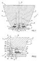
- the reference number 1 designates as a whole an electronic lighting device comprising four LEDs 2, only two of which are visible in Figure 1 , of the type made on respective discrete electronic components and mounted on a substantially plane support 3 so as to be centred on the vertices of a square ( Figure 2 ), a control unit (not illustrated) for controlling electrical supply of the LEDs 2, and an optical system 4 made according to the present invention positioned above the LEDs 2 for collecting and mixing the light emitted by the LEDs 2 themselves.
- the support 3 on which the LEDs 2 are mounted is constituted, for example, by a printed-circuit board made on which are the electrical connections between the LEDs 2 and the control unit.
- the LEDs 2 are designed to emit respective light radiation of different colours, chosen as desired according to the colour and the tone of colour of the light that it is desired to obtain at output from the optical system 4.
- the optical system 4 comprises an optical mixer body 5, which is made of a transparent material, and in particular polymethyl methacrylate (known by the acronym PMMA), and presents an axial symmetry with respect to a longitudinal axis 6, an inlet window 7, which is perpendicular to the axis 6 and through which the light to be mixed emitted by the LEDs 2 is collected, and an outlet window 8, which is perpendicular to the axis 6 and from which mixed light exits.
- PMMA polymethyl methacrylate
- the mixer body 5 is designed to be mounted on the support 3 with the axis 6 perpendicular thereto at the centroid of the square in which the LEDs 2 are arranged in such a way that these are set facing the inlet window 7.
- the mixer body 5 comprises four longitudinal portions 9 contiguous to one another, each of which is associated to a respective one of the LEDs 2, extends between the inlet window 7 and the outlet window 8 and has a respective optical axis 10 substantially parallel to the axis 6 and a respective focus 11 lying on the optical axis 10 in a position corresponding to the inlet window 7.
- the optical axes 10 are set at equal distances apart from the axis 6 so that each focus 11 will be centred on the corresponding LED 2 to enable the light emitted by the LED 2 to be collected and conveyed, towards the outlet window 8, by the respective longitudinal portion 9.
- the optical axes 10 are arranged in such a way that each vertex of the square in which the LEDs 2 are arranged will lie substantially on a respective optical axis 10. Visible in Figure 1 are only two of the four longitudinal portions 9, i.e., those associated to the two visible LEDs 2.
- the light collected by the longitudinal portions 9 propagates within the mixer body 5 from the inlet window 7 to the outlet window 8 according to rays that are slightly divergent with respect to the optical axes 10, hence undergoing a process of optical mixing.
- the outlet window 8 of the mixer body 5 is constituted by a layer of small lenses (not illustrated) of a known type designed to increase the divergence of the rays of outgoing light.
- the optical system 4 further comprises a reflector device 12 set in a position corresponding to the inlet window 7 of the mixer body 5 and set between the LEDs 2 for separating the LEDs 2 optically from one another in such a way that all the light emitted by each LED 2 will be collected by the respective longitudinal portion 9.
- the reflector device 12 comprises four concave reflecting surfaces 13 arranged according to an axial symmetry with respect to the axis 6 and associated, each, to a respective LED 2, and hence to a respective longitudinal portion 9.
- each reflecting surface 13 are such that a part of light that the corresponding LED 2 emits laterally towards the longitudinal portions 9 associated to the other LEDs 2 and that, in the absence of the reflecting surface 13 itself, would be collected by said longitudinal portions 9, is, instead, reflected in such a way as to be collected by the longitudinal portion 9 associated to said LED 2, as will be explained better hereinafter.
- the mixer body 5 comprises a pin 14, which projects from the surface of the inlet window 7 sharing the axis 6 and is designed to engage a blind hole 15 made axially in the reflector device 12 for connecting the latter, fixedly and coaxially, to the mixer body 5.
- the inlet window 7 comprises four subwindows 16, each of which is associated to a respective longitudinal portion 9.
- Each subwindow 16 has a surface made on which is an aspherical convergent lens 17, which has a focus coinciding with the focus 11 of the corresponding longitudinal portion 9, and a plurality of Fresnel halfrings ( Figure 2 ), hereinafter referred to as a whole and for reasons of simplicity as Fresnel lens 18, operating as a convergent lens.
- each subwindow 16 further comprises a portion of lateral surface 19 obtained substantially by rotation, through a quarter of a full circle about the corresponding optical axis 10, of a first broken line 20 ( Figure 2 ) comprising a plurality of segments (not illustrated) forming, in a plane passing through the optical axis 10, respective angles with respect to the optical axis 10 itself.
- each reflecting surface 13 is set with its own concavity facing the portion of lateral surface 19 of the respective longitudinal portion 9 in such a way that the corresponding LEDs 2 will be substantially positioned between the reflecting surface 13 and the portion of lateral surface 19 ( Figure 2 ).
- each longitudinal portion 9 has a lateral surface 21 of separation between the transparent medium of the mixer body 5 and the surrounding air, the lateral surface of which is designated by 21, extends between the subwindow 16 and the outlet window 8 and is obtained substantially by rotation, of a quarter of a full circle about the corresponding optical axis 10, of a second broken line 22 comprising a plurality of segments (not illustrated) forming, in a plane passing through the optical axis 10, respective angles with respect to the optical axis 10 itself.
- each reflecting surface 13 is obtained by rotation, through half of a full circle about the corresponding optical axis 10, of a generatrix 23 defined in a plane (not illustrated) passing through the optical axis 10.
- the reflecting surface 13 has a semicircular cross section along any plane orthogonal to the axis 6.
- the generatrix 23 comprises a first curve 24, which is defined by a respective second-degree polynomial function, and a second curve 25, which has one end coinciding with one end of the curve 24 and is constituted by a succession of six curves (not illustrated) radiused to one another and defined by respective mathematical functions.
- the two end curves of the succession of curves are defined by respective sixth-degree polynomial functions
- the two central curves of the succession of curves are defined by respective root functions
- the remaining two curves, which are positioned, each, between a respective end curve and the central curves are defined by respective eighth-degree polynomial functions.
- the curves 24 and 25 are not radiused to one another. Following the mechanism of generation by rotation described above, the curve 24 generates a first portion 26 of the reflecting surface 13 set with an edge 26a of its own contiguous to the corresponding Fresnel lens 18 ( Figure 2 ), and the curve 25 generates a second portion 27 of the reflecting surface 13 set with an edge 27a of its own contiguous to the corresponding LED 2.
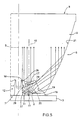
- Figure 5 illustrates one of the longitudinal portions 9 and the corresponding reflecting surface 13 of the view of Figure 1 , where, however, the section filling lines have been removed for reasons of greater clarity.
- each LED 2 can be considered as being made up of multiple light beams that have different orientations with respect to the optical axis 10 of the longitudinal portion 9 associated to said LED 2 and that are hence collected from different portions by the respective subwindow 16 and are then conveyed, during their propagation within the longitudinal portion 9, towards the outlet window 8 in directions slightly divergent from the optical axis 10, i.e., in directions forming with the optical axis 10 angles smaller than or equal to 10°. Said divergence causes the light beams collected by the various longitudinal portions 9 to mix with one another during their propagation towards the outlet window 8.
- a first one of said light beams, designated by 28, emitted centrally with respect to the corresponding optical axis 10, and in particular a conical beam 28 sharing the optical axis 10 and having its vertex substantially on the corresponding focus 11, is collected by the lens 7 and is then conveyed towards the outlet window 8 in said divergent directions.
- Another beam 29 emitted laterally with respect to the optical axis 10 and substantially oriented towards the other subwindows 16, and in particular oriented towards the pin 14, is intercepted by the first portion 26 of the reflecting surface 13 and is then reflected on, and collected by, the Fresnel lens 18, which conveys the beam 29 collected towards the outlet window 8 in said divergent directions.
- a fourth beam 31, emitted laterally with respect to the optical axis 10 in such a way as to be substantially oriented towards the other subwindows 16, and in particular oriented specularly, with respect to the optical axis 10, to a part of the beam 30, is, instead, intercepted by the second portion 27 of the reflecting surface 13 and is then reflected on, and collected by, the portion of lateral surface 19.
- the set of the beams 29 and 31 constitutes a beam emitted specularly, with respect to the optical axis 10, to the beam 30.
- the lateral surface 21 is designed to reflect, via total internal reflection, the beams 30 and 31 collected by the portion of lateral surface 19 so that they converge in said divergent directions.
- optical system 4 comprises a number of longitudinal portions 9 different from four to adapt to electronic devices comprising a number of LEDs 2 different from four, provided that said LEDs 2 are arranged at the vertices of a regular polygon, for example, an equilateral triangle, or else a pentagon.
- the portion of lateral surface 19 of each subwindow 16 and the lateral surface 21 of each longitudinal portion 9 are obtained by rotation of a submultiple of a full circle, said submultiple depending upon the number of the LEDs 2, for example, one third of a full circle in the case of three LEDs 2 or one fifth of a full circle in the case of five LEDs 2.
- each longitudinal portion 9 must be sized in such a way that each of said optical axes 10 passes through a respective vertex of said regular polygon.
- the main advantage of the optical system 4 described above is to supply, at the outlet window 8, a concentrated light spot, which is optimally mixed, albeit presenting external dimensions comparable to those of known optical systems, thanks to the particular division of the mixer body 5 into the multiple longitudinal portions 9 associated to the respective LEDs 2 and appropriately shaped in a position corresponding to the inlet window 7 and the lateral surface 21.
- Another advantage is that an efficiency is obtained, in terms of ratio between the amount of light emitted by the LEDs 2 and the amount of mixed light supplied by the outlet window 8 given the same external dimensions, that is very high, up to 75%, thanks to the particular reflector device 12 set between the LEDs 2, which recovers a part of the light emitted laterally by each LED 2 that would be lost and/or collected in an inefficient way by the longitudinal portions 9 associated to the other LEDs 2 producing, in particular, undesirable patches of colour in the light spot supplied at the outlet window 8.
- the optical system 4 enables maximum freedom in the choice and control of the LED components 2 in order to obtain the desired colour and/or light intensity at the outlet window 8. For example, it enables choice of the combination of colours of the LEDs 2 on the basis of the commercial availability of discrete components, which is much wider than that of integrated components, or else, it enables a lighting device to be provided, which is able to control as desired the brightness and the tone of the light spot at output by appropriately controlling the electrical supply of the LEDs 2, or else, it enables use of a number of LEDs 2 all of the same colour to obtain a light spot of that colour but having a much higher light intensity.
- an optical system 4 according to the following points.
Landscapes
- Engineering & Computer Science (AREA)
- General Engineering & Computer Science (AREA)
- Non-Portable Lighting Devices Or Systems Thereof (AREA)
Description
- The present invention relates to an optical system for mixing the light emitted by a plurality of light sources.
- In particular, the present invention finds advantageous, though non-exclusive, application in mixing of the light emitted by a plurality of light sources constituted by LEDs, to which the ensuing description will make explicit reference without this implying any loss of generality.
- Currently existing on the market are electronic components that integrate a plurality of LEDs, which are able to emit respective light radiation of different colours. For example, very widespread on the market are electronic components that integrate three LEDs, which are arranged at the vertices of a triangle and are able to emit light in the three fundamental colours, i.e., red, green and blue. Given that a LED source can be considered as a Lambertian point source with a wide angle of emission, the integration of three LEDs in a single component substantially enables approximation, from the optical standpoint, of the three light sources with a single Lambertian point source.
- Likewise known are electronic lighting devices of the type comprising a plurality of LEDs integrated in a single electronic component and an optical system for mixing the light emitted by said LEDs, said optical system being designed so as to exploit the single-point-source approximation.
- An optical system of the above sort is normally constituted by a single body made of transparent material having an index of refraction higher than that of the air. Said body has an optical axis, an inlet window perpendicular to the optical axis for collecting the light to be mixed, and an outlet window for supplying mixed light, which is also perpendicular to the optical axis and is designed to be set with the optical axis in a centred position between the LEDs in such a way that the latter will all face the inlet window. The inlet window normally has a central portion of surface shaped like a single convergent lens, which is coaxial to the optical axis and is set with its own focus in a position substantially centred between the LEDs for collecting rays of light emitted with small angles with respect to the optical axis, and a portion of lateral surface that surrounds the convergent lens for collecting rays of light emitted with large angles with respect to the optical axis. The body has a lateral outer surface, the curvature of which is such as to intercept and reflect, by total internal reflection, the rays of light collected by the inlet window in such a way that they will be conveyed in directions slightly divergent with respect to the optical axis. Said divergence enables the rays of light collected to be mixed together in an efficient way.
- However, the efficiency of the optical systems mentioned above drops drastically in the case of use of discrete LED components, which can hence no longer be considered as a single point source even if they are mounted close to one another according to a regular arrangement. The use of discrete LEDs is necessary when it is desired not to be tied down to the format of the integrated components with a number of LEDs that are commercially, i.e., when it is desired to use a different number of LEDs with different combinations of basic colours in order to create new colours or different tones of one and the same basic colour. Said need is increasingly felt in various contexts, such as architecture, theatrical shows, and lighting techniques in general.
- A known solution to said problem is that of appropriately sizing, and in particular oversizing, the optical system so as to be able to fit within the single-point-source approximation. Unfortunately, to obtain an efficiency equal to the one that is obtained with LEDs integrated in a single electronic component, it is necessary to increase the dimensions of the optical system, and this is particularly disagreeable from the aesthetic and functional standpoint in the contexts of use mentioned above.
- The aim of the present invention is to provide an optical system for mixing the light emitted by a number of discrete LED components that will be free from the drawbacks described above and, at the same time, will be easy and inexpensive to produce.
- Provided according to the present invention is an optical system for mixing the light emitted by a plurality of light sources according to the annexed claims.
- The present invention will now be described with reference to the annexed drawings, which illustrate a non-limiting example of embodiment thereof, and in which:
-
Figure 1 illustrates, according to a view in longitudinal section, an electronic lighting device comprising a plurality of LEDs and the optical system made according to the teachings of the present invention; -
Figure 2 illustrates in greater detail a portion of the optical system ofFigure 1 ; -
Figure 3 illustrates, according to a view in elevation from beneath, the optical system made according to the present invention; -
Figure 4 illustrates, according to an axonometric view, a component of the optical system ofFigure 1 ; and -
Figure 5 is a schematic illustration of the operation of the optical system ofFigure 1 in the presence of light emitted by the LEDs. - In
Figure 1 , the reference number 1 designates as a whole an electronic lighting device comprising fourLEDs 2, only two of which are visible inFigure 1 , of the type made on respective discrete electronic components and mounted on a substantiallyplane support 3 so as to be centred on the vertices of a square (Figure 2 ), a control unit (not illustrated) for controlling electrical supply of theLEDs 2, and anoptical system 4 made according to the present invention positioned above theLEDs 2 for collecting and mixing the light emitted by theLEDs 2 themselves. Thesupport 3 on which theLEDs 2 are mounted is constituted, for example, by a printed-circuit board made on which are the electrical connections between theLEDs 2 and the control unit. TheLEDs 2 are designed to emit respective light radiation of different colours, chosen as desired according to the colour and the tone of colour of the light that it is desired to obtain at output from theoptical system 4. - The
optical system 4 comprises anoptical mixer body 5, which is made of a transparent material, and in particular polymethyl methacrylate (known by the acronym PMMA), and presents an axial symmetry with respect to alongitudinal axis 6, aninlet window 7, which is perpendicular to theaxis 6 and through which the light to be mixed emitted by theLEDs 2 is collected, and anoutlet window 8, which is perpendicular to theaxis 6 and from which mixed light exits. - The
mixer body 5 is designed to be mounted on thesupport 3 with theaxis 6 perpendicular thereto at the centroid of the square in which theLEDs 2 are arranged in such a way that these are set facing theinlet window 7. In particular, themixer body 5 comprises fourlongitudinal portions 9 contiguous to one another, each of which is associated to a respective one of theLEDs 2, extends between theinlet window 7 and theoutlet window 8 and has a respectiveoptical axis 10 substantially parallel to theaxis 6 and arespective focus 11 lying on theoptical axis 10 in a position corresponding to theinlet window 7. Theoptical axes 10 are set at equal distances apart from theaxis 6 so that eachfocus 11 will be centred on thecorresponding LED 2 to enable the light emitted by theLED 2 to be collected and conveyed, towards theoutlet window 8, by the respectivelongitudinal portion 9. In other words, theoptical axes 10 are arranged in such a way that each vertex of the square in which theLEDs 2 are arranged will lie substantially on a respectiveoptical axis 10. Visible inFigure 1 are only two of the fourlongitudinal portions 9, i.e., those associated to the twovisible LEDs 2. - As will be explained better hereinafter, the light collected by the
longitudinal portions 9 propagates within themixer body 5 from theinlet window 7 to theoutlet window 8 according to rays that are slightly divergent with respect to theoptical axes 10, hence undergoing a process of optical mixing. In order to improve mixing of the light at output from theoptical system 4, theoutlet window 8 of themixer body 5 is constituted by a layer of small lenses (not illustrated) of a known type designed to increase the divergence of the rays of outgoing light. - The
optical system 4 further comprises areflector device 12 set in a position corresponding to theinlet window 7 of themixer body 5 and set between theLEDs 2 for separating theLEDs 2 optically from one another in such a way that all the light emitted by eachLED 2 will be collected by the respectivelongitudinal portion 9. In particular, thereflector device 12 comprises four concave reflectingsurfaces 13 arranged according to an axial symmetry with respect to theaxis 6 and associated, each, to arespective LED 2, and hence to a respectivelongitudinal portion 9. The curvature and arrangement of each reflectingsurface 13 are such that a part of light that thecorresponding LED 2 emits laterally towards thelongitudinal portions 9 associated to theother LEDs 2 and that, in the absence of the reflectingsurface 13 itself, would be collected by saidlongitudinal portions 9, is, instead, reflected in such a way as to be collected by thelongitudinal portion 9 associated to saidLED 2, as will be explained better hereinafter. - The
mixer body 5 comprises apin 14, which projects from the surface of theinlet window 7 sharing theaxis 6 and is designed to engage ablind hole 15 made axially in thereflector device 12 for connecting the latter, fixedly and coaxially, to themixer body 5. - With reference to
Figure 2 , which illustrates in greater detail a portion of the cross-sectional view ofFigure 1 , and toFigure 3 , which illustrates theoptical system 4 according to a view from theinlet window 7 orthogonal to theaxis 6, theinlet window 7 comprises foursubwindows 16, each of which is associated to a respectivelongitudinal portion 9. Eachsubwindow 16 has a surface made on which is an asphericalconvergent lens 17, which has a focus coinciding with thefocus 11 of the correspondinglongitudinal portion 9, and a plurality of Fresnel halfrings (Figure 2 ), hereinafter referred to as a whole and for reasons of simplicity as Fresnellens 18, operating as a convergent lens. The Fresnellens 18 is coaxial and confocal to thelens 17 and is set between the latter and thepin 14 so as to surround thelens 17 partially. The surface of eachsubwindow 16 further comprises a portion oflateral surface 19 obtained substantially by rotation, through a quarter of a full circle about the correspondingoptical axis 10, of a first broken line 20 (Figure 2 ) comprising a plurality of segments (not illustrated) forming, in a plane passing through theoptical axis 10, respective angles with respect to theoptical axis 10 itself. In addition, each reflectingsurface 13 is set with its own concavity facing the portion oflateral surface 19 of the respectivelongitudinal portion 9 in such a way that thecorresponding LEDs 2 will be substantially positioned between the reflectingsurface 13 and the portion of lateral surface 19 (Figure 2 ). - With reference to
Figure 2 , eachlongitudinal portion 9 has alateral surface 21 of separation between the transparent medium of themixer body 5 and the surrounding air, the lateral surface of which is designated by 21, extends between thesubwindow 16 and theoutlet window 8 and is obtained substantially by rotation, of a quarter of a full circle about the correspondingoptical axis 10, of a secondbroken line 22 comprising a plurality of segments (not illustrated) forming, in a plane passing through theoptical axis 10, respective angles with respect to theoptical axis 10 itself. - With reference to
Figure 2 and toFigure 4 , which illustrates just thereflector device 12 according to an axonometric view, the curvature of each reflectingsurface 13 is obtained by rotation, through half of a full circle about the correspondingoptical axis 10, of ageneratrix 23 defined in a plane (not illustrated) passing through theoptical axis 10. In other words, the reflectingsurface 13 has a semicircular cross section along any plane orthogonal to theaxis 6. Thegeneratrix 23 comprises afirst curve 24, which is defined by a respective second-degree polynomial function, and asecond curve 25, which has one end coinciding with one end of thecurve 24 and is constituted by a succession of six curves (not illustrated) radiused to one another and defined by respective mathematical functions. To be precise, the two end curves of the succession of curves are defined by respective sixth-degree polynomial functions, the two central curves of the succession of curves are defined by respective root functions, and the remaining two curves, which are positioned, each, between a respective end curve and the central curves, are defined by respective eighth-degree polynomial functions. - The
curves curve 24 generates afirst portion 26 of the reflectingsurface 13 set with anedge 26a of its own contiguous to the corresponding Fresnel lens 18 (Figure 2 ), and thecurve 25 generates asecond portion 27 of the reflectingsurface 13 set with anedge 27a of its own contiguous to thecorresponding LED 2. - Operation of the
optical system 4 is described hereinafter with particular reference toFigure 5 , which illustrates one of thelongitudinal portions 9 and the corresponding reflectingsurface 13 of the view ofFigure 1 , where, however, the section filling lines have been removed for reasons of greater clarity. - The light emitted by each
LED 2 can be considered as being made up of multiple light beams that have different orientations with respect to theoptical axis 10 of thelongitudinal portion 9 associated to saidLED 2 and that are hence collected from different portions by therespective subwindow 16 and are then conveyed, during their propagation within thelongitudinal portion 9, towards theoutlet window 8 in directions slightly divergent from theoptical axis 10, i.e., in directions forming with theoptical axis 10 angles smaller than or equal to 10°. Said divergence causes the light beams collected by the variouslongitudinal portions 9 to mix with one another during their propagation towards theoutlet window 8. - In particular, a first one of said light beams, designated by 28, emitted centrally with respect to the corresponding
optical axis 10, and in particular aconical beam 28 sharing theoptical axis 10 and having its vertex substantially on thecorresponding focus 11, is collected by thelens 7 and is then conveyed towards theoutlet window 8 in said divergent directions. Anotherbeam 29 emitted laterally with respect to theoptical axis 10 and substantially oriented towards theother subwindows 16, and in particular oriented towards thepin 14, is intercepted by thefirst portion 26 of thereflecting surface 13 and is then reflected on, and collected by, the Fresnellens 18, which conveys thebeam 29 collected towards theoutlet window 8 in said divergent directions. Afurther beam 30, emitted laterally with respect to theoptical axis 10 and oriented in the direction of recession from theother LEDs 2, i.e., towards thelateral surface 21, is collected directly, i.e., without any intermediate reflections, by the portion oflateral surface 19. Afourth beam 31, emitted laterally with respect to theoptical axis 10 in such a way as to be substantially oriented towards theother subwindows 16, and in particular oriented specularly, with respect to theoptical axis 10, to a part of thebeam 30, is, instead, intercepted by thesecond portion 27 of thereflecting surface 13 and is then reflected on, and collected by, the portion oflateral surface 19. The set of thebeams optical axis 10, to thebeam 30. Thelateral surface 21 is designed to reflect, via total internal reflection, thebeams lateral surface 19 so that they converge in said divergent directions. - Further variants not illustrated of the
optical system 4 according to the present invention comprise a number oflongitudinal portions 9 different from four to adapt to electronic devices comprising a number ofLEDs 2 different from four, provided that saidLEDs 2 are arranged at the vertices of a regular polygon, for example, an equilateral triangle, or else a pentagon. In these cases, the portion oflateral surface 19 of each subwindow 16 and thelateral surface 21 of eachlongitudinal portion 9 are obtained by rotation of a submultiple of a full circle, said submultiple depending upon the number of theLEDs 2, for example, one third of a full circle in the case of threeLEDs 2 or one fifth of a full circle in the case of fiveLEDs 2. In other words, eachlongitudinal portion 9 must be sized in such a way that each of saidoptical axes 10 passes through a respective vertex of said regular polygon. - The main advantage of the
optical system 4 described above, as compared to the optical systems known at the current state of the art and suitable for being applied on three LEDs integrated in just one electronic component, is to supply, at theoutlet window 8, a concentrated light spot, which is optimally mixed, albeit presenting external dimensions comparable to those of known optical systems, thanks to the particular division of themixer body 5 into the multiplelongitudinal portions 9 associated to therespective LEDs 2 and appropriately shaped in a position corresponding to theinlet window 7 and thelateral surface 21. - Another advantage is that an efficiency is obtained, in terms of ratio between the amount of light emitted by the
LEDs 2 and the amount of mixed light supplied by theoutlet window 8 given the same external dimensions, that is very high, up to 75%, thanks to theparticular reflector device 12 set between theLEDs 2, which recovers a part of the light emitted laterally by eachLED 2 that would be lost and/or collected in an inefficient way by thelongitudinal portions 9 associated to theother LEDs 2 producing, in particular, undesirable patches of colour in the light spot supplied at theoutlet window 8. - Finally, the
optical system 4 according to the present invention enables maximum freedom in the choice and control of theLED components 2 in order to obtain the desired colour and/or light intensity at theoutlet window 8. For example, it enables choice of the combination of colours of theLEDs 2 on the basis of the commercial availability of discrete components, which is much wider than that of integrated components, or else, it enables a lighting device to be provided, which is able to control as desired the brightness and the tone of the light spot at output by appropriately controlling the electrical supply of theLEDs 2, or else, it enables use of a number ofLEDs 2 all of the same colour to obtain a light spot of that colour but having a much higher light intensity. - According to further aspects, there is provided an
optical system 4 according to the following points. - 1. An optical system for mixing the light emitted by a plurality of light sources (2); the optical system (4) comprising an optical mixer body (5), which is made of transparent material and has an inlet window (7) for collecting the light emitted by the light sources (2), an outlet window (8) for supplying mixed light, and a longitudinal axis (6) transverse to the inlet and outlet windows (7, 8); the optical system (4) being characterized in that the mixer body (5) comprises a plurality of longitudinal portions (9) contiguous to one another, each of which is associated to a respective one of said light sources (2), extends between the inlet window (7) and the outlet window (8), has a respective optical axis (10) parallel to the longitudinal axis (6) and a respective focus (11) lying on the optical axis (10) in a position corresponding to the inlet window (7); the optical system (4) being designed to be positioned with each focus (11) centred on the respective light source (2) so that the light emitted thereby will be collected and conveyed, towards the outlet window (8), by the respective longitudinal portion (9).
- 2. The optical system according to point 1, wherein said light sources (2) are centred on respective vertices of a regular polygon; said optical axes (10) being set at equal distances apart from said longitudinal axis (6) in such a way that each vertex of said polygon will lie substantially on a respective optical axis (10).
- 3. The optical system according to
point 2, wherein said plurality of light sources comprises four light sources (2) centred on the vertices of a square. - 4. The optical system according to one of the preceding points, wherein each of said light sources is a LED (2).
Claims (15)
- An optical system for mixing the light emitted by a plurality of light sources (2); the optical system (4) comprising an optical mixer body (5), which is made of transparent material and has an inlet window (7) for collecting the light emitted by the light sources (2), an outlet window (8) for supplying mixed light, and a longitudinal axis (6) transverse to the inlet and outlet windows (7, 8); the optical system (4) being characterized in that the mixer body (5) comprises a plurality of longitudinal portions (9) contiguous to one another, each of which is associated to a respective one of said light sources (2), extends between the inlet window (7) and the outlet window (8), has a respective optical axis (10) parallel to the longitudinal axis (6) and a respective focus (11) lying on the optical axis (10) in a position corresponding to the inlet window (7); the optical system (4) being designed to be positioned with each focus (11) centred on the respective light source (2) so that the light emitted thereby will be collected and conveyed, towards the outlet window (8), by the respective longitudinal portion (9).
- The optical system according to Claim 1, wherein said inlet window (7) comprises a plurality of subwindows (16), each of which is associated to a respective one of said longitudinal portions (9); each of said light sources (2) being designed to emit a respective first light beam (31) oriented towards the subwindows (16) of the other longitudinal portions (9); the optical system (4) comprising reflector means (12), which are arranged in a position corresponding to said inlet window (7) so as to be set between the light sources (2) and are designed to reflect the first light beam (31) of each light source (2) in such a way that said first light beam (31) will be collected by the subwindow (16) corresponding to said light source (2).
- The optical system according to Claim 2, wherein each of said light sources (2) is designed to emit a respective second light beam (28) sharing said optical axis (10) of the respective said longitudinal portion (9); each of said subwindows (16) comprising a respective first lens (17), which is confocal to said focus (11) of the respective longitudinal portion (9) and is designed to collect the second light beam (28) for conveying it towards said outlet window (8).
- The optical system according to Claim 2 or Claim 3, wherein each of said light sources (2) is designed to emit a respective third light beam (30) oriented in a direction of recession from the other light sources (2); each of said subwindows (16) presenting a respective portion of lateral surface (19), which is obtained by partial rotation, about said optical axis (10) of the respective longitudinal portion (9), of a first broken line (20) defined in a plane passing through the optical axis (10) and is designed to collect directly the third light beam (30) of the corresponding light source (2).
- The optical system according to Claim 4, wherein said reflector means (12) are designed to reflect said second light beam (28) of each light source (2) in such a way that the second light beam (28) itself will be collected by the portion of lateral surface (19) of the subwindow (16) corresponding to said light source (2).
- The optical system according to Claim 5, wherein each of said longitudinal portions (9) comprises a respective lateral surface (21), which extends between said inlet window (7) and said outlet window (8), is obtained by partial rotation, about said optical axis (10) of the longitudinal portion (9), of a second broken line (22) defined in a plane passing through the optical axis (10), and is designed to reflect, via total internal reflection, the light beams (30, 31) collected by said portion of lateral surface (19) of the respective subwindow (16) in such a way as to convey said light beams (30, 31) towards the outlet window (8).
- The optical system according to any one of Claims 2 to 6, wherein each of said light sources (2) is designed to emit a fourth light beam (29) oriented towards the subwindows (16) of the other longitudinal portions (9); each of said subwindows (16) comprising a respective second lens (18), which comprises a plurality of Fresnel halfrings and is confocal to said focus (11) of the respective longitudinal portion (9); said reflector means (12) being designed to reflect the fourth light beam (29) of each light source (2) towards the second lens (18) corresponding to said light source (2); the second lens (18) being designed to collect the fourth light beam (29) for conveying it towards said outlet window (8).
- The optical system according to any one of Claims 2 to 7, wherein said reflector means (12) comprise a plurality of concave reflecting surfaces (13), each of which is associated to a respective one of said longitudinal portions (9) and has a semicircular cross section in any plane orthogonal to said longitudinal axis (6).
- The optical system according to any one of Claims 5 to 8, wherein said reflector means (12) comprise a plurality of concave reflecting surfaces (13), each of which is associated to a respective one of said longitudinal portions (9) and is positioned with its concavity facing said portion of lateral surface (19) of the subwindow (16) corresponding to said longitudinal portion (9).
- The optical system according to any one of Claims 5 to 9, wherein each said reflecting surface (13) comprises a first portion of surface (27), which is obtained by rotation, through half of a full circle about said optical axis (10) of the respective longitudinal portion (9), of a first curve (25) defined in a plane passing through the optical axis (10), and is designed to intercept and reflect said first light beam (31) of the respective source in such a way that the first light beam (31) itself will be collected by said portion of lateral surface (19) of the subwindow (16) corresponding to said longitudinal portion (9).
- The optical system according to Claim 10, wherein said first curve (25) comprises a succession of a pre-set number of third curve radiused to one another and defined by respective mathematical functions; at least one of said third curves being defined by a polynomial function of a degree higher than three.
- The optical system according to Claim 7, wherein said reflector means (12) comprise a plurality of concave reflecting surfaces (13), each of which is associated to a respective one of said longitudinal portions (9); each reflecting surface (13) comprising a second portion of surface (26), which is obtained by rotation, through half of a full circle about said optical axis (10) of the respective longitudinal portion (9), of a second curve (24) defined in a plane passing through the optical axis (10), and is designed to intercept said fourth light beam (29) of the respective light source (2) to reflect it onto said second lens (18) corresponding to said longitudinal portion (9); said second curve (24) being defined by a second-degree polynomial function.
- The optical system according to one of the preceding claims, wherein said light sources (2) are centred on respective vertices of a regular polygon; said optical axes (10) being set at equal distances apart from said longitudinal axis (6) in such a way that each vertex of said polygon will lie substantially on a respective optical axis (10).
- The optical system according to one of the preceding claims, wherein each of said light sources (2) is designed to emit a light radiation of a respective colour.
- The optical system according to one of the preceding claims, wherein said light emitted by each said light source (2) comprises a respective plurality of light beams (28-31), and the respective said longitudinal portion (9) is designed to collect said light beams (28-31) and convey them towards the outlet window (8) in respective directions forming, with said respective optical axis (10), angles smaller than or equal to 10° in such a way that the plurality of light beams (28-31) collected by the various longitudinal portions (9) mix together during their propagation towards the outlet window (8).
Applications Claiming Priority (1)
| Application Number | Priority Date | Filing Date | Title |
|---|---|---|---|
| PCT/IT2008/000140 WO2009110011A1 (en) | 2008-03-03 | 2008-03-03 | Optical system for mixing the light emitted by a plurality of light sources |
Publications (2)
| Publication Number | Publication Date |
|---|---|
| EP2257445A1 EP2257445A1 (en) | 2010-12-08 |
| EP2257445B1 true EP2257445B1 (en) | 2014-05-07 |
Family
ID=40084390
Family Applications (1)
| Application Number | Title | Priority Date | Filing Date |
|---|---|---|---|
| EP08751489.9A Active EP2257445B1 (en) | 2008-03-03 | 2008-03-03 | Optical system for mixing the light emitted by a plurality of light sources |
Country Status (2)
| Country | Link |
|---|---|
| EP (1) | EP2257445B1 (en) |
| WO (1) | WO2009110011A1 (en) |
Families Citing this family (5)
| Publication number | Priority date | Publication date | Assignee | Title |
|---|---|---|---|---|
| FR2961290B1 (en) * | 2010-06-10 | 2012-07-27 | Cooper Technologies Co | LIGHTING DEVICE |
| FR2962783B1 (en) * | 2010-07-15 | 2014-11-14 | Cooper Technologies Co | THERMAL DISSIPATING LIGHTING DEVICE |
| NL2008163C2 (en) | 2012-01-20 | 2013-07-25 | Orga Holding B V | Beacon light optic, beacon light, method for obtaining a beacon light optic. |
| US9435515B2 (en) | 2014-01-31 | 2016-09-06 | Energizer Brands, Llc | Near-field lens with convex hyperbolic surface |
| CN112902117B (en) * | 2021-01-18 | 2025-04-01 | 深圳极光王科技股份有限公司 | Lamp mixing device and lamp mixing method |
Family Cites Families (4)
| Publication number | Priority date | Publication date | Assignee | Title |
|---|---|---|---|---|
| US6547416B2 (en) * | 2000-12-21 | 2003-04-15 | Koninklijke Philips Electronics N.V. | Faceted multi-chip package to provide a beam of uniform white light from multiple monochrome LEDs |
| JP4153370B2 (en) * | 2002-07-04 | 2008-09-24 | 株式会社小糸製作所 | Vehicle lighting |
| DE10314524A1 (en) * | 2003-03-31 | 2004-10-28 | Osram Opto Semiconductors Gmbh | Headlights and headlight element |
| EP1826474A1 (en) * | 2006-02-22 | 2007-08-29 | Optics Lite S.r.L. | Optical projector with radial LED light source |
-
2008
- 2008-03-03 WO PCT/IT2008/000140 patent/WO2009110011A1/en not_active Ceased
- 2008-03-03 EP EP08751489.9A patent/EP2257445B1/en active Active
Also Published As
| Publication number | Publication date |
|---|---|
| EP2257445A1 (en) | 2010-12-08 |
| WO2009110011A1 (en) | 2009-09-11 |
Similar Documents
| Publication | Publication Date | Title |
|---|---|---|
| US9435506B2 (en) | Lighting device in a motor vehicle having a plate-shaped light conductor and a rod-shaped light conductor | |
| EP2093482A2 (en) | An apparatus and method for improved illumination area fill | |
| EP2756224B1 (en) | High recycling efficiency solid state light source device | |
| US11668445B2 (en) | Multi-beam vehicle light | |
| CN101652686B (en) | Lighting structure | |
| CN107023796B (en) | Collimating lens and optical module for automobile | |
| CN104755832A (en) | Lighting systems providing direct and indirect lighting | |
| EP2604521B1 (en) | Combined aircraft landing and taxi light | |
| US8465180B2 (en) | Optical element for asymmetric light distribution | |
| US20090046459A1 (en) | Lighting device | |
| EP2257445A1 (en) | Optical system for mixing the light emitted by a plurality of light sources | |
| US20140078730A1 (en) | Lamp system having parabolic reflector with two reflections for recycling light | |
| CN207762609U (en) | Collimate LED lens and collimation LED light | |
| CN103994395A (en) | Led optical system and lamp | |
| US8356914B2 (en) | Luminaires and optics for control and distribution of multiple quasi point source light sources such as LEDs | |
| US7600894B1 (en) | Luminaires and optics for control and distribution of multiple quasi point source light sources such as LEDs | |
| CN109519870A (en) | Realize the optical system of uniformly light-emitting | |
| CN101675330B (en) | Led illumination for line scan camera | |
| CN116557807B (en) | Evenly illuminate thick-walled structures and headlights | |
| CN112628621A (en) | Laser light source device | |
| US9651218B2 (en) | Lighting modules with optimized emission | |
| CN208620295U (en) | A kind of Film Optics lens and lighting device with micro-structure | |
| JP2017212036A (en) | Vehicular lighting fixture | |
| CN220523936U (en) | Thick wall assembly with uniform lighting | |
| US7025484B2 (en) | Light source |
Legal Events
| Date | Code | Title | Description |
|---|---|---|---|
| PUAI | Public reference made under article 153(3) epc to a published international application that has entered the european phase |
Free format text: ORIGINAL CODE: 0009012 |
|
| 17P | Request for examination filed |
Effective date: 20101004 |
|
| AK | Designated contracting states |
Kind code of ref document: A1 Designated state(s): AT BE BG CH CY CZ DE DK EE ES FI FR GB GR HR HU IE IS IT LI LT LU LV MC MT NL NO PL PT RO SE SI SK TR |
|
| AX | Request for extension of the european patent |
Extension state: AL BA MK RS |
|
| DAX | Request for extension of the european patent (deleted) | ||
| RAP1 | Party data changed (applicant data changed or rights of an application transferred) |
Owner name: DATALOGIC AUTOMATION S.R.L. |
|
| REG | Reference to a national code |
Ref country code: DE Ref legal event code: R079 Ref document number: 602008032078 Country of ref document: DE Free format text: PREVIOUS MAIN CLASS: B60Q0001000000 Ipc: F21V0005040000 |
|
| RIC1 | Information provided on ipc code assigned before grant |
Ipc: F21Y 101/02 20060101ALI20130827BHEP Ipc: F21V 13/04 20060101ALI20130827BHEP Ipc: F21V 5/04 20060101AFI20130827BHEP Ipc: F21V 7/00 20060101ALI20130827BHEP |
|
| GRAP | Despatch of communication of intention to grant a patent |
Free format text: ORIGINAL CODE: EPIDOSNIGR1 |
|
| INTG | Intention to grant announced |
Effective date: 20131007 |
|
| GRAS | Grant fee paid |
Free format text: ORIGINAL CODE: EPIDOSNIGR3 |
|
| RAP1 | Party data changed (applicant data changed or rights of an application transferred) |
Owner name: DATALOGIC IP TECH S.R.L. |
|
| GRAA | (expected) grant |
Free format text: ORIGINAL CODE: 0009210 |
|
| AK | Designated contracting states |
Kind code of ref document: B1 Designated state(s): AT BE BG CH CY CZ DE DK EE ES FI FR GB GR HR HU IE IS IT LI LT LU LV MC MT NL NO PL PT RO SE SI SK TR |
|
| REG | Reference to a national code |
Ref country code: GB Ref legal event code: FG4D |
|
| REG | Reference to a national code |
Ref country code: AT Ref legal event code: REF Ref document number: 666986 Country of ref document: AT Kind code of ref document: T Effective date: 20140515 |
|
| REG | Reference to a national code |
Ref country code: IE Ref legal event code: FG4D |
|
| REG | Reference to a national code |
Ref country code: DE Ref legal event code: R096 Ref document number: 602008032078 Country of ref document: DE Effective date: 20140626 |
|
| REG | Reference to a national code |
Ref country code: AT Ref legal event code: MK05 Ref document number: 666986 Country of ref document: AT Kind code of ref document: T Effective date: 20140507 |
|
| REG | Reference to a national code |
Ref country code: NL Ref legal event code: VDEP Effective date: 20140507 |
|
| REG | Reference to a national code |
Ref country code: LT Ref legal event code: MG4D |
|
| PG25 | Lapsed in a contracting state [announced via postgrant information from national office to epo] |
Ref country code: GR Free format text: LAPSE BECAUSE OF FAILURE TO SUBMIT A TRANSLATION OF THE DESCRIPTION OR TO PAY THE FEE WITHIN THE PRESCRIBED TIME-LIMIT Effective date: 20140808 Ref country code: FI Free format text: LAPSE BECAUSE OF FAILURE TO SUBMIT A TRANSLATION OF THE DESCRIPTION OR TO PAY THE FEE WITHIN THE PRESCRIBED TIME-LIMIT Effective date: 20140507 Ref country code: NO Free format text: LAPSE BECAUSE OF FAILURE TO SUBMIT A TRANSLATION OF THE DESCRIPTION OR TO PAY THE FEE WITHIN THE PRESCRIBED TIME-LIMIT Effective date: 20140807 Ref country code: CY Free format text: LAPSE BECAUSE OF FAILURE TO SUBMIT A TRANSLATION OF THE DESCRIPTION OR TO PAY THE FEE WITHIN THE PRESCRIBED TIME-LIMIT Effective date: 20140507 Ref country code: IS Free format text: LAPSE BECAUSE OF FAILURE TO SUBMIT A TRANSLATION OF THE DESCRIPTION OR TO PAY THE FEE WITHIN THE PRESCRIBED TIME-LIMIT Effective date: 20140907 Ref country code: LT Free format text: LAPSE BECAUSE OF FAILURE TO SUBMIT A TRANSLATION OF THE DESCRIPTION OR TO PAY THE FEE WITHIN THE PRESCRIBED TIME-LIMIT Effective date: 20140507 |
|
| PG25 | Lapsed in a contracting state [announced via postgrant information from national office to epo] |
Ref country code: AT Free format text: LAPSE BECAUSE OF FAILURE TO SUBMIT A TRANSLATION OF THE DESCRIPTION OR TO PAY THE FEE WITHIN THE PRESCRIBED TIME-LIMIT Effective date: 20140507 Ref country code: ES Free format text: LAPSE BECAUSE OF FAILURE TO SUBMIT A TRANSLATION OF THE DESCRIPTION OR TO PAY THE FEE WITHIN THE PRESCRIBED TIME-LIMIT Effective date: 20140507 Ref country code: PL Free format text: LAPSE BECAUSE OF FAILURE TO SUBMIT A TRANSLATION OF THE DESCRIPTION OR TO PAY THE FEE WITHIN THE PRESCRIBED TIME-LIMIT Effective date: 20140507 Ref country code: HR Free format text: LAPSE BECAUSE OF FAILURE TO SUBMIT A TRANSLATION OF THE DESCRIPTION OR TO PAY THE FEE WITHIN THE PRESCRIBED TIME-LIMIT Effective date: 20140507 Ref country code: SE Free format text: LAPSE BECAUSE OF FAILURE TO SUBMIT A TRANSLATION OF THE DESCRIPTION OR TO PAY THE FEE WITHIN THE PRESCRIBED TIME-LIMIT Effective date: 20140507 Ref country code: LV Free format text: LAPSE BECAUSE OF FAILURE TO SUBMIT A TRANSLATION OF THE DESCRIPTION OR TO PAY THE FEE WITHIN THE PRESCRIBED TIME-LIMIT Effective date: 20140507 |
|
| PG25 | Lapsed in a contracting state [announced via postgrant information from national office to epo] |
Ref country code: PT Free format text: LAPSE BECAUSE OF FAILURE TO SUBMIT A TRANSLATION OF THE DESCRIPTION OR TO PAY THE FEE WITHIN THE PRESCRIBED TIME-LIMIT Effective date: 20140908 |
|
| PG25 | Lapsed in a contracting state [announced via postgrant information from national office to epo] |
Ref country code: RO Free format text: LAPSE BECAUSE OF FAILURE TO SUBMIT A TRANSLATION OF THE DESCRIPTION OR TO PAY THE FEE WITHIN THE PRESCRIBED TIME-LIMIT Effective date: 20140507 Ref country code: BE Free format text: LAPSE BECAUSE OF FAILURE TO SUBMIT A TRANSLATION OF THE DESCRIPTION OR TO PAY THE FEE WITHIN THE PRESCRIBED TIME-LIMIT Effective date: 20140507 Ref country code: EE Free format text: LAPSE BECAUSE OF FAILURE TO SUBMIT A TRANSLATION OF THE DESCRIPTION OR TO PAY THE FEE WITHIN THE PRESCRIBED TIME-LIMIT Effective date: 20140507 Ref country code: SK Free format text: LAPSE BECAUSE OF FAILURE TO SUBMIT A TRANSLATION OF THE DESCRIPTION OR TO PAY THE FEE WITHIN THE PRESCRIBED TIME-LIMIT Effective date: 20140507 Ref country code: CZ Free format text: LAPSE BECAUSE OF FAILURE TO SUBMIT A TRANSLATION OF THE DESCRIPTION OR TO PAY THE FEE WITHIN THE PRESCRIBED TIME-LIMIT Effective date: 20140507 Ref country code: DK Free format text: LAPSE BECAUSE OF FAILURE TO SUBMIT A TRANSLATION OF THE DESCRIPTION OR TO PAY THE FEE WITHIN THE PRESCRIBED TIME-LIMIT Effective date: 20140507 |
|
| REG | Reference to a national code |
Ref country code: DE Ref legal event code: R097 Ref document number: 602008032078 Country of ref document: DE |
|
| PG25 | Lapsed in a contracting state [announced via postgrant information from national office to epo] |
Ref country code: NL Free format text: LAPSE BECAUSE OF FAILURE TO SUBMIT A TRANSLATION OF THE DESCRIPTION OR TO PAY THE FEE WITHIN THE PRESCRIBED TIME-LIMIT Effective date: 20140507 |
|
| PLBE | No opposition filed within time limit |
Free format text: ORIGINAL CODE: 0009261 |
|
| STAA | Information on the status of an ep patent application or granted ep patent |
Free format text: STATUS: NO OPPOSITION FILED WITHIN TIME LIMIT |
|
| 26N | No opposition filed |
Effective date: 20150210 |
|
| REG | Reference to a national code |
Ref country code: DE Ref legal event code: R097 Ref document number: 602008032078 Country of ref document: DE Effective date: 20150210 |
|
| PG25 | Lapsed in a contracting state [announced via postgrant information from national office to epo] |
Ref country code: SI Free format text: LAPSE BECAUSE OF FAILURE TO SUBMIT A TRANSLATION OF THE DESCRIPTION OR TO PAY THE FEE WITHIN THE PRESCRIBED TIME-LIMIT Effective date: 20140507 |
|
| PG25 | Lapsed in a contracting state [announced via postgrant information from national office to epo] |
Ref country code: MC Free format text: LAPSE BECAUSE OF FAILURE TO SUBMIT A TRANSLATION OF THE DESCRIPTION OR TO PAY THE FEE WITHIN THE PRESCRIBED TIME-LIMIT Effective date: 20140507 Ref country code: LU Free format text: LAPSE BECAUSE OF FAILURE TO SUBMIT A TRANSLATION OF THE DESCRIPTION OR TO PAY THE FEE WITHIN THE PRESCRIBED TIME-LIMIT Effective date: 20150303 |
|
| REG | Reference to a national code |
Ref country code: CH Ref legal event code: PL |
|
| REG | Reference to a national code |
Ref country code: IE Ref legal event code: MM4A |
|
| PG25 | Lapsed in a contracting state [announced via postgrant information from national office to epo] |
Ref country code: IE Free format text: LAPSE BECAUSE OF NON-PAYMENT OF DUE FEES Effective date: 20150303 Ref country code: CH Free format text: LAPSE BECAUSE OF NON-PAYMENT OF DUE FEES Effective date: 20150331 Ref country code: LI Free format text: LAPSE BECAUSE OF NON-PAYMENT OF DUE FEES Effective date: 20150331 |
|
| REG | Reference to a national code |
Ref country code: FR Ref legal event code: PLFP Year of fee payment: 9 |
|
| PG25 | Lapsed in a contracting state [announced via postgrant information from national office to epo] |
Ref country code: MT Free format text: LAPSE BECAUSE OF FAILURE TO SUBMIT A TRANSLATION OF THE DESCRIPTION OR TO PAY THE FEE WITHIN THE PRESCRIBED TIME-LIMIT Effective date: 20140507 |
|
| REG | Reference to a national code |
Ref country code: FR Ref legal event code: PLFP Year of fee payment: 10 |
|
| PG25 | Lapsed in a contracting state [announced via postgrant information from national office to epo] |
Ref country code: HU Free format text: LAPSE BECAUSE OF FAILURE TO SUBMIT A TRANSLATION OF THE DESCRIPTION OR TO PAY THE FEE WITHIN THE PRESCRIBED TIME-LIMIT; INVALID AB INITIO Effective date: 20080303 Ref country code: BG Free format text: LAPSE BECAUSE OF FAILURE TO SUBMIT A TRANSLATION OF THE DESCRIPTION OR TO PAY THE FEE WITHIN THE PRESCRIBED TIME-LIMIT Effective date: 20140507 |
|
| PG25 | Lapsed in a contracting state [announced via postgrant information from national office to epo] |
Ref country code: TR Free format text: LAPSE BECAUSE OF FAILURE TO SUBMIT A TRANSLATION OF THE DESCRIPTION OR TO PAY THE FEE WITHIN THE PRESCRIBED TIME-LIMIT Effective date: 20140507 |
|
| REG | Reference to a national code |
Ref country code: FR Ref legal event code: PLFP Year of fee payment: 11 |
|
| P01 | Opt-out of the competence of the unified patent court (upc) registered |
Effective date: 20230530 |
|
| PGFP | Annual fee paid to national office [announced via postgrant information from national office to epo] |
Ref country code: GB Payment date: 20240320 Year of fee payment: 17 |
|
| PGFP | Annual fee paid to national office [announced via postgrant information from national office to epo] |
Ref country code: IT Payment date: 20240329 Year of fee payment: 17 Ref country code: FR Payment date: 20240322 Year of fee payment: 17 |
|
| GBPC | Gb: european patent ceased through non-payment of renewal fee |
Effective date: 20250303 |
|
| PG25 | Lapsed in a contracting state [announced via postgrant information from national office to epo] |
Ref country code: GB Free format text: LAPSE BECAUSE OF NON-PAYMENT OF DUE FEES Effective date: 20250303 |
|
| PG25 | Lapsed in a contracting state [announced via postgrant information from national office to epo] |
Ref country code: IT Free format text: LAPSE BECAUSE OF NON-PAYMENT OF DUE FEES Effective date: 20250303 Ref country code: FR Free format text: LAPSE BECAUSE OF NON-PAYMENT OF DUE FEES Effective date: 20250331 |
|
| PGFP | Annual fee paid to national office [announced via postgrant information from national office to epo] |
Ref country code: DE Payment date: 20260319 Year of fee payment: 19 |