EP2257056A1 - Broadcast receiving apparatus and channel searching method thereof - Google Patents
Broadcast receiving apparatus and channel searching method thereof Download PDFInfo
- Publication number
- EP2257056A1 EP2257056A1 EP09714152A EP09714152A EP2257056A1 EP 2257056 A1 EP2257056 A1 EP 2257056A1 EP 09714152 A EP09714152 A EP 09714152A EP 09714152 A EP09714152 A EP 09714152A EP 2257056 A1 EP2257056 A1 EP 2257056A1
- Authority
- EP
- European Patent Office
- Prior art keywords
- channel
- signal
- bit error
- error rate
- tuner unit
- Prior art date
- Legal status (The legal status is an assumption and is not a legal conclusion. Google has not performed a legal analysis and makes no representation as to the accuracy of the status listed.)
- Withdrawn
Links
Images
Classifications
-
- H—ELECTRICITY
- H04—ELECTRIC COMMUNICATION TECHNIQUE
- H04N—PICTORIAL COMMUNICATION, e.g. TELEVISION
- H04N5/00—Details of television systems
- H04N5/44—Receiver circuitry for the reception of television signals according to analogue transmission standards
- H04N5/52—Automatic gain control
-
- H—ELECTRICITY
- H04—ELECTRIC COMMUNICATION TECHNIQUE
- H04N—PICTORIAL COMMUNICATION, e.g. TELEVISION
- H04N5/00—Details of television systems
- H04N5/44—Receiver circuitry for the reception of television signals according to analogue transmission standards
- H04N5/50—Tuning indicators; Automatic tuning control
-
- H—ELECTRICITY
- H04—ELECTRIC COMMUNICATION TECHNIQUE
- H04H—BROADCAST COMMUNICATION
- H04H40/00—Arrangements specially adapted for receiving broadcast information
- H04H40/18—Arrangements characterised by circuits or components specially adapted for receiving
-
- H—ELECTRICITY
- H04—ELECTRIC COMMUNICATION TECHNIQUE
- H04N—PICTORIAL COMMUNICATION, e.g. TELEVISION
- H04N21/00—Selective content distribution, e.g. interactive television or video on demand [VOD]
- H04N21/40—Client devices specifically adapted for the reception of or interaction with content, e.g. set-top-box [STB]; Operations thereof
- H04N21/43—Processing of content or additional data, e.g. demultiplexing additional data from a digital video stream; Elementary client operations, e.g. monitoring of home network or synchronising decoder's clock; Client middleware
- H04N21/438—Interfacing the downstream path of the transmission network originating from a server, e.g. retrieving encoded video stream packets from an IP network
- H04N21/4383—Accessing a communication channel
-
- H—ELECTRICITY
- H04—ELECTRIC COMMUNICATION TECHNIQUE
- H04N—PICTORIAL COMMUNICATION, e.g. TELEVISION
- H04N21/00—Selective content distribution, e.g. interactive television or video on demand [VOD]
- H04N21/40—Client devices specifically adapted for the reception of or interaction with content, e.g. set-top-box [STB]; Operations thereof
- H04N21/43—Processing of content or additional data, e.g. demultiplexing additional data from a digital video stream; Elementary client operations, e.g. monitoring of home network or synchronising decoder's clock; Client middleware
- H04N21/442—Monitoring of processes or resources, e.g. detecting the failure of a recording device, monitoring the downstream bandwidth, the number of times a movie has been viewed, the storage space available from the internal hard disk
- H04N21/44209—Monitoring of downstream path of the transmission network originating from a server, e.g. bandwidth variations of a wireless network
-
- H—ELECTRICITY
- H04—ELECTRIC COMMUNICATION TECHNIQUE
- H04N—PICTORIAL COMMUNICATION, e.g. TELEVISION
- H04N21/00—Selective content distribution, e.g. interactive television or video on demand [VOD]
- H04N21/40—Client devices specifically adapted for the reception of or interaction with content, e.g. set-top-box [STB]; Operations thereof
- H04N21/47—End-user applications
- H04N21/482—End-user interface for programme selection
Definitions
- the embodiment relates to a broadcasting receiver and a method for searching a channel thereof.
- broadcasting media are digitalized
- digital broadcasting such as ground-wave broadcasting or satellite broadcasting
- the digital broadcasting has actively progressed due to the introduction of a digital system into cable broadcasting.
- a broadcasting signal is digitalized, so that media utilizing a compression scheme is spread. Accordingly, the convergence of communication, a computer, and broadcasting can be accelerated.
- a unitary medium having multiple functions can be globalized and support multiple channels, so that various data services can be provided.
- the embodiment provides a broadcasting receiver and a method for searching a channel thereof, capable of storing a channel searched in a search mode and resetting a signal reception state of the stored channel.
- the embodiment provides a broadcasting receiver and a method for searching a channel thereof, capable of determining if the channel is stored according to a bit error rate of a broadcasting signal and resetting the signal reception state of the stored channel.
- the embodiment provides a broadcasting receiver and a method for searching a channel thereof, capable of determining if the channel is stored according to a bit error rate of a broadcasting signal, which has passed through a booster and a tuner unit, and setting the signal reception state of the stored channel to the optimal state.
- a method for searching a channel of a broadcasting receiver includes searching and storing a channel wherein a broadcasting signal represents a bit error rate less than or equal to a reference bit error rate among channels selected by a tuner unit, and resetting signal adjusting parameters of the tuner unit according to a reception state of the broadcasting signal of the stored channel.
- the broadcasting receiver includes a tuner unit to convert a high frequency signal of a channel selected in a channel search mode into an intermediate frequency signal, a demodulator to demodulate the intermediate frequency signal of the tuner unit and detect a bit error rate, a controller to check a bit error rate of a signal received in the tuner unit to determine if information about a channel of the signal is stored, and reset a signal reception state of the channel, and a storage unit to store the information about the channel by the controller.
- the embodiment can reduce search time for a broadcast channel.
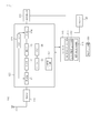
- FIG. 1 is a block diagram showing a broadcasting receiver 100 according to the first embodiment.
- the broadcasting receiver 100 includes a booster (a first amplifier) 113, a tuner unit 120, a demodulator 130, a controller 140, a storage unit 150, and a key input section 160.
- the broadcasting receiver 100 is a set to receive and process a broadcasting signal, which has been modulated through at least one scheme, and can be realized by using a TV set, a Set-top Box, a DVD (DVD-RW or DVD+RW), and a PVR (personal video recorder).
- a TV set a Set-top Box
- DVD DVD-RW or DVD+RW
- PVR personal video recorder
- the booster 113 is turned on or off by the controller 140 and amplifies or passes through a signal that has been received through an antenna 111. If a high frequency signal of a channel received through the antenna 111 represents weak electric field strength, the booster 113 is turned on to amplify the high frequency signal, thereby improving received electric field strength somewhat. If the high frequency signal of the channel received through the antenna 111 represents strong electric field strength, the booster 113 is turned off to pass through the high frequency signal.
- the tuner unit 120 includes an RF (radio frequency) amplifier 121, a filter 122, a mixer 123, an IF (Intermediate Frequency) amplifier 124, a PLL (Phase Locked Loop) circuit 125, an OSC (oscillator) 126, a charge pump 127, and an AGC (Auto Gain Control) circuit 128.
- the tuner unit 120 selects a specific channel in a search mode of the controller 140, and converts the signal of the selected channel into an IF signal to be output.
- the RF amplifier 121 amplifies an input high frequency signal to a predetermined level.
- the RF amplifier 121 can be realized by using an LNA (Low Noise Amplifier) to reduce the noise of the signal and increase receive sensitivity.
- LNA Low Noise Amplifier
- the filter 122 passes through a signal having a specific wavelength band among signals amplified by the RF amplifier 121, and cuts off signals having other wavelength bands.
- the filter 122 may be realized by using a BPF (Band Pass Filter), but the present invention is not limited thereto.
- the mixer 123 converts the signal, which has passed through the filter 122, into an IF signal.
- the mixer 123 mixes the high frequency signal of the filter 122 with a local frequency signal of the OSC 126 to output the IF signal.
- the IF amplifier 124 amplifies the IF signal, which is output from the mixer 123, and outputs the IF signal.
- the PLL circuit 125 outputs a reference frequency of the selected channel to the OSC 126, and the OSC 126 outputs a local frequency by using the reference frequency.
- the charge pump 127 controls the tuning voltage of the PLL circuit 125.
- the charge pump 127 changes lock time of the PLL circuit 125 by using a current gain according to pulses. In other words, the charge pump 127 becomes a parameter to determine the quantity of current to be supplied in order to control the tuning voltage of the PLL circuit 125.
- the mixer 123, the PLL circuit 125, the OSC 126, and the charge pump 127 may be integrated into an MOPLL (mixer oscillator phase looked loop) IC.
- the MOPLL IC is realized in the form of one chip.
- the MOPLL IC converts a high frequency into an IF and outputs the IF.
- the AGC circuit 128 detects the gain of a received signal based on the output of the mixer 123, and then regulates the gains of the RF amplifier 121 and the IF amplifier 124.
- the AGC circuit 128 includes an auto gain controller, and the auto gain controller changes the time constant of the AGC circuit 128 (AGC TIME CONSTANT) .
- AGC TIME CONSTANT changes the time constant of the AGC circuit 128
- the auto gain controller adjusts the gain of the broadcasting receiver 100 to a predetermined output level by changing the AGC TIME CONSTANT. For example, if the state of the received signal is normal, the AGC TIME CONSTANT may be changed into SLOW. The AGC TIME CONSTANT may be changed into FAST according to the state of the received signal.
- the AGC circuit 128 may include an AGC detector, and the AGC detector regulates the gain of the RF amplifier 121 by using an AGC TOP (Take Over Point).
- the value of the AGC TOP may be set based on sensitivity, the capability of excluding an adjacent channel, the capability of excluding external noise, QRM, and the like.
- the tuner unit 120 is a CAN (Control Area Network) type tuner, deviation may occur in the power gain and the noise of each channel.
- the AGC TOP is set based on the variation in the power gain and the noise of a signal.
- the demodulator 130 demodulates the IF signal of the tuner unit 120 into an original signal.
- the demodulation scheme varies depending on broadcasting scheme, and the broadcasting scheme may include DTTB (Digital Terrestrial Television Broadcasting) or digital cable broadcasting, but the present invention is not limited thereto.
- the DTTB signal has been modulated through an OFDM (Orthogonal Frequency Division Multiplexing) scheme, and the digital cable broadcasting signal has been modulated through a QAM (Quadrature amplitude modulation) scheme.
- the demodulator 130 demodulates the IF signal of the tuner unit 120 through the broadcasting scheme of the input signal to output the IF signal in the form of a transport stream.
- the transport stream that has been demodulated by the demodulator 130 is delivered to a decoder (not shown).
- the demodulator 130 may include an error correction code.
- the error correction code is used to detect a BER (bit error rate) of the broadcasting signal and store the BER in a register.
- the BER is delivered to the controller 140. In this case, as the BER detected based on the error correction code is lowered, the broadcasting signal represents better quality. In contrast, as the BER is increased, the broadcasting signal represents worse quality.
- the demodulator 130 detects a BER for each signal adjusting parameter of the tuner unit 120.
- the signal adjusting parameters include the BER of the AGC TIME CONSTANT, the BER of the AGC TOP, and the BER of the charge pump 127.
- the tuner unit 120 and the demodulator 130 may be realized by using an NIM (Network Interface Module).
- the tuner unit 120 may be realized by using a half NIM tuner that is not provided in the demodulator 130.
- the controller 140 can be connected to the tuner unit 120 by using a clock signal and a data signal.
- the controller 140 checks the BER of a parameter relating to a signal reception state by a preset program to control the performance of an MOPLL IC of the tuner unit 120.
- the controller 140 controls the booster (the first amplifier) 113, the tuner unit 120, and the demodulator 130 according to keys input into the key input unit 160.
- the controller 140 controls an on/off operation of the booster (the first amplifier) 113 and a channel searching operation of the tuner unit 120.
- Such the channel searching operation optimizes the reception state of a signal from each channel according to the area or the communication environment of the broadcasting receiver.
- the controller 140 includes a channel searchmodule 141, a signal adjusting module 143, and a BER (Bit Error Rate) check module 145.
- the channel search module 141 sets the booster 113 to an on-state or an off-state, and controls the channel selection of the tuner unit 120.
- the channel search module 141 determines if a channel is stored or not according to the BER of the channel selected through the BER check module 145. If the BER of the broadcasting signal of the selected channel is less than or equal to a reference BER, the information about the selected channel is stored in the storage unit 150.
- the channel search module 141 checks the BER of the broadcasting signal in the on/off state of the booster 113 and stores information about a channel where the broadcasting signal represents a BER less than or equal to the reference BER in the storage unit 150.
- the signal adjusting module 143 resets signal adjusting parameters according to the signal reception state of the channel stored in the storage unit 150.
- the signal adjusting parameters are reset in such a manner that the BERs of the AGC TIME CONSTANT, the AGC TOP, and the charge pump of the signal received through the channel are less than or equal to the reference BER.
- the BERs of the signal adjusting parameters may increase or decrease according to the installation position, the installation area, or the communication environment of the broadcasting receiver. Since the BER is based on the temporal statistics, the BER having a fixed value is utilized as a reference BER.
- the BERs of the signal adjusting parameters are checked during a predetermined period of time and a statistical value thereof is calculated. If the statistical value of the BERs is less than or equal to a reference value, the screen image of the channel represents good quality. If the statistical value of the BERs exceeds the reference value, the screen image of the channel represents bad quality.
- the signal adjusting module 143 changes the signal adjusting parameters until the BER of each signal adjusting parameter is less than or equal to the reference value. When the BER is changed, the signal reception state of the stored channel is optimized.
- the BER check module 145 checks the BER of each signal received therein from the demodulator 130 and provides the BER to the channel search module 141 and the signal adjusting module 143.
- the channel search module 141 stores the channels representing BERs less than or equal to a reference BER in the storage unit 150 based on the BER of the channel checked by the BER check module 145.
- the signal adjusting module 143 resets the signal reception state of the stored channel to optimize the signal reception state of each channel.
- the controller 140 reduces time spent in the channel selection because the signal adjusting module 143 sets only the signal reception state of the stored channel without setting signal reception states of all channels.
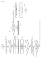
- FIG. 2 is a flowchart showing a method for searching a channel according to the second embodiment.
- the second embodiment will be described with reference to description of components of FIG. 1 .
- a channel searching request is received (step S101)
- the BER of the broadcasting signal that has been received is detected by the demodulator 130.
- the controller 140 checks the BER of the broadcasting signal that has been received through the channel (step S105), and determines if the BER is less than or equal to a reference BER R BER .
- the BER of the broadcasting signal is detected based on an error correction code of the demodulator 130. The check and comparison of the BER of each channel may be performed by the controller 140.
- the information about the selected channel is stored in the storage unit 150 (step S107).
- the information about the channel stored in the first search mode may include information about the frequency of each channel and information about the on-state of the booster 113.
- step S108 After the information about the channel has been stored, it is determined if the channel searching operation has been completed (step S108). If the channel searching operation has not been completed, a next channel is selected. If the BER of the broadcasting signal of the selected channel is less than or equal to the reference BER R BER , the channel is stored in the storage unit 150.
- the channel searching operation is performed with respect to all channels, and information about a channel where the broadcasting signal represents a BER less than or equal to the reference BER R BER among the searched channels is stored.
- a second search mode is performed (step S109).
- the booster 113 is turned off (step S110), and the search for all channels is performed.
- the second search mode when the booster 113 is turned off, all channels are sequentially selected (Step S104). It is determined if BERs of broadcasting signals of the channels are less than or equal to the reference BER R BER (steps S105 and S106), and the information about the channel where the broadcasting signal represents the BER less than or equal to the reference BER R BER is stored in the storage unit 150 (step S107).
- the information about the channels stored in the second search mode includes information about the frequency of each channel and information about the off-state of the booster 113.
- the channel can be searched by shifting the on-state of the booster into the off-state or shifting the off-state of the booster into the on-state of the booster.
- a signal adjusting mode is performed (step S111).
- the signal adjusting module 142 of the controller 140 sets signal adjusting parameters according to the signal reception state of the channel stored in the storage unit 150 (step S112).
- the signal adjusting parameters are reset according to the position, the area, or the communication environment of the broadcasting receiver, so that the optimal signal can be output.
- the signal adjusting parameters include the AGC TIME CONSTANT, the AGC TOP, and the charge pump, and can be set as optimal values according to the signal reception state.
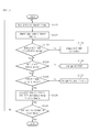
- FIG. 3 is a flowchart showingamethodof setting signal adjusting parameters according to one embodiment. The following description related to FIG. 3 will be made with reference to description of the components of FIG. 1 .
- a channel stored in the storage unit 150 is loaded, and selected by the tuner unit 120 (step S120).
- the booster 113 is turned on or off according to the information about the channel.
- the demodulator 130 checks the reception state of a signal that has been demodulated (Step S121).
- the signal reception state of the channel may be set to the optimal reception state by adjusting the signal adjusting parameters of the tuner unit 120.
- the signal adjusting parameters may include the AGC TIME CONSTANT, the AGC TOP, and the charge pump.
- the AGC TIME CONSTANT is used to regulate the gain of the broadcasting receiver such that the signal intensity received in the tuner unit 120 can be maintained at a predetermined output level when the signal intensity is changed due to fading or other environment conditions.
- the AGC TOP is used to regulate the gain of the RF amplifier 121.
- the charge pump is used to regulate the tuning voltage of the PLL circuit 125.
- the signal adjusting parameters are used to adjust the received signal based on the initial values thereof.
- the initial values have been preset in the manufacture line or predetermined when searching for a previous channel.
- Step S122 is to determine if the BER of the AGC TIME CONSTANT is less than or equal to a reference BER based on the signal reception state of the channel when the initial value is applied to the AGC TIME CONSTANT. If the AGC TIME CONSTANT is not proper, the signal adjusting module 143 of the controller 140 changes the AGC TIME CONSTANT (step S123). The above process may repeat to set the optimal AGC TIME CONSTANT satisfying that the BER of the AGC TIME CONSTANT for the channel is less than or equal to the reference BER.
- Step S124 is to determine if the BER of the AGC TOP is less than or equal to the reference BER based on the signal reception state of the channel when the initial value is applied to the AGC TOP. If the BER of the AGC TOP is not proper, the signal adjusting module 143 of the controller 140 changes the AGC TOP (step S125) .
- the above process may repeat to set the optimal AGC TOP satisfying that the BER of the AGC TOP for the channel is less than or equal to the reference BER.
- Step S126 is to determine if the BER of the charge pump is less than or equal to the reference BER based on the signal reception state of the channel when the initial value is applied to the charge pump. If the BER of the charge pump is not proper, the signal adjusting module 143 of the controller 140 changes the value of the charge pump (step S127). The above process may repeat to set the optimal value of the charge pump satisfying that the BER of the charge pump for the channel is less than or equal to the reference BER.
- the AGC TIME CONSTANT, the AGC TOP, and the charge pump value for each channel are stored (step S128).
- the stored parameter values are used to set the signal reception state of each channel stored in the storage unit 150 to the optimal state.
- step S129 It is determined if the setting of the stored channel have been completed (step S129). If the setting of the storage channel has not been completed according to the determination result, the channel stored in the storage unit 150 is loaded, and a channel is selected. Therefore, the above process may repeat.
- the resetting of the signal adjusting parameters is not performed with respect to all channels but performed with respect to the channel stored in the storage unit 150. Accordingly, time to search a channel can be reduced.
- the resetting sequence of the AGC TIME CONSTANT, the AGC TOP, and the charge pump value may be changed, but the present invention is not limited thereto.
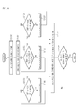
- FIG. 4 is a flowchart showing a method of resetting the signal adjusting parameters of FIG. 2 according to another embodiment.
- the following description related to FIG. 4 will be made based on the description of the components of FIG. 1 .
- the channel stored in the storage unit 150 is loaded, and the tuner unit 120 selects the loaded channel (step S130).
- the booster 113 is turned on or off according to the information about the channel.
- the BER of a signal demodulated by the demodulator 130 is checked (step S131).
- the signal reception state of the channel can be set to the optimal reception state by adjusting the signal adjusting parameters of the tuner unit 120.
- the signal adjusting parameters may include the AGC TIME CONSTANT, the AGC TOP, and the charge pump.
- the AGC TIME CONSTANT is used to regulate the gain of the broadcasting receiver such that the intensity of a signal received in the tuner unit 120 can be maintained at a predetermined output level when the signal intensity is changed due to fading or other environment conditions.
- the AGC TOP is used to regulate the gain of the RF amplifier 121.
- the charge pump is used to regulate the tuning voltage of the PLL circuit.
- the above signal adjusting parameters are initial values and used to regulate the received signal. The initial values may be set in the manufacture line or set when searching for a previous channel.
- step S132, S133, and S134 It is determined if the AGC TIME CONSTANT, the AGC TOP, and the charge pump value for the signal received through the channel are proper (step S132, S133, and S134).
- the AGC TIME CONSTANT is changed until the BER of the AGC TIME CONSTANT is proper (step S135).
- the BER of the AGC TIME CONSTANT becomes proper when the BER of the AGC TIME CONSTANT is less than or equal to the reference BER with respect to the signal of the channel.
- the AGC TOP is changed until the BER of the AGC TOP is proper (step S136).
- the BER of the AGC TOP becomes proper when the BER of the AGC TOP is less than or equal to the reference BER with respect to the signal of the channel.
- the charge pump value is changed until the BER of the charge pump is proper (step S137).
- the BER of the charge pump becomes proper when the BER of the charge pump is less than or equal to the reference BER with respect to the signal of the channel.
- the AGC TIME CONSTANT, the AGC TOP, and the charge pump values for each channel are stored (step S138).
- the values of the signal adjusting parameters for each channel allow the signal received in each channel to be in an optimal reception state.
- step S139 it is determined if the setting of the stored channel has been completed. If the setting of the stored channel has not been completed, another stored channel is loaded and selected, and the above process may repeat.
- the embodiment is applicable to a broadcasting receiver.
- the embodiment is applicable to a digital broadcasting receiver.
- a tuner to selectively process a ground wave signal and a cable signal can be installed in sets such as a TV, a DVD, a PVR, and a set-top box.
Landscapes
- Engineering & Computer Science (AREA)
- Signal Processing (AREA)
- Multimedia (AREA)
- Computer Networks & Wireless Communication (AREA)
- Databases & Information Systems (AREA)
- Human Computer Interaction (AREA)
- Circuits Of Receivers In General (AREA)
Abstract
Description
- The embodiment relates to a broadcasting receiver and a method for searching a channel thereof.
- As broadcasting media are digitalized, digital broadcasting such as ground-wave broadcasting or satellite broadcasting has been commenced. Recently, the digital broadcasting has actively progressed due to the introduction of a digital system into cable broadcasting. In addition, a broadcasting signal is digitalized, so that media utilizing a compression scheme is spread. Accordingly, the convergence of communication, a computer, and broadcasting can be accelerated. Further, a unitary medium having multiple functions can be globalized and support multiple channels, so that various data services can be provided.
- The embodiment provides a broadcasting receiver and a method for searching a channel thereof, capable of storing a channel searched in a search mode and resetting a signal reception state of the stored channel.
- The embodiment provides a broadcasting receiver and a method for searching a channel thereof, capable of determining if the channel is stored according to a bit error rate of a broadcasting signal and resetting the signal reception state of the stored channel.
- The embodiment provides a broadcasting receiver and a method for searching a channel thereof, capable of determining if the channel is stored according to a bit error rate of a broadcasting signal, which has passed through a booster and a tuner unit, and setting the signal reception state of the stored channel to the optimal state.
- According to the embodiment, a method for searching a channel of a broadcasting receiver includes searching and storing a channel wherein a broadcasting signal represents a bit error rate less than or equal to a reference bit error rate among channels selected by a tuner unit, and resetting signal adjusting parameters of the tuner unit according to a reception state of the broadcasting signal of the stored channel.
- According to the embodiment, the broadcasting receiver includes a tuner unit to convert a high frequency signal of a channel selected in a channel search mode into an intermediate frequency signal, a demodulator to demodulate the intermediate frequency signal of the tuner unit and detect a bit error rate, a controller to check a bit error rate of a signal received in the tuner unit to determine if information about a channel of the signal is stored, and reset a signal reception state of the channel, and a storage unit to store the information about the channel by the controller.
- The embodiment can reduce search time for a broadcast channel.
-
-
FIG. 1 is a block diagram showing a broadcasting receiver according to a first embodiment; -
FIG. 2 is a flowchart showing a method for searching a channel according to a second embodiment; -
FIG. 3 is a flowchart showing a method for resetting signal adjusting parameters ofFIG. 2 according to one embodiment; and -
FIG. 4 is a flowchart showing a method for resetting signal adjusting parameters ofFIG. 2 according to another embodiment. - Hereinafter, embodiments will be described with reference to accompanying drawings.
-
FIG. 1 is a block diagram showing abroadcasting receiver 100 according to the first embodiment. - Referring to
FIG. 1 , thebroadcasting receiver 100 includes a booster (a first amplifier) 113, atuner unit 120, ademodulator 130, acontroller 140, astorage unit 150, and akey input section 160. - The
broadcasting receiver 100 is a set to receive and process a broadcasting signal, which has been modulated through at least one scheme, and can be realized by using a TV set, a Set-top Box, a DVD (DVD-RW or DVD+RW), and a PVR (personal video recorder). - The
booster 113 is turned on or off by thecontroller 140 and amplifies or passes through a signal that has been received through anantenna 111. If a high frequency signal of a channel received through theantenna 111 represents weak electric field strength, thebooster 113 is turned on to amplify the high frequency signal, thereby improving received electric field strength somewhat. If the high frequency signal of the channel received through theantenna 111 represents strong electric field strength, thebooster 113 is turned off to pass through the high frequency signal. - The
tuner unit 120 includes an RF (radio frequency)amplifier 121, afilter 122, amixer 123, an IF (Intermediate Frequency)amplifier 124, a PLL (Phase Locked Loop)circuit 125, an OSC (oscillator) 126, acharge pump 127, and an AGC (Auto Gain Control)circuit 128. - The
tuner unit 120 selects a specific channel in a search mode of thecontroller 140, and converts the signal of the selected channel into an IF signal to be output. - The
RF amplifier 121 amplifies an input high frequency signal to a predetermined level. TheRF amplifier 121 can be realized by using an LNA (Low Noise Amplifier) to reduce the noise of the signal and increase receive sensitivity. - The
filter 122 passes through a signal having a specific wavelength band among signals amplified by theRF amplifier 121, and cuts off signals having other wavelength bands. Thefilter 122 may be realized by using a BPF (Band Pass Filter), but the present invention is not limited thereto. - The
mixer 123 converts the signal, which has passed through thefilter 122, into an IF signal. Themixer 123 mixes the high frequency signal of thefilter 122 with a local frequency signal of theOSC 126 to output the IF signal. TheIF amplifier 124 amplifies the IF signal, which is output from themixer 123, and outputs the IF signal. - The
PLL circuit 125 outputs a reference frequency of the selected channel to theOSC 126, and theOSC 126 outputs a local frequency by using the reference frequency. Thecharge pump 127 controls the tuning voltage of thePLL circuit 125. - The
charge pump 127 changes lock time of thePLL circuit 125 by using a current gain according to pulses. In other words, thecharge pump 127 becomes a parameter to determine the quantity of current to be supplied in order to control the tuning voltage of thePLL circuit 125. - The
mixer 123, thePLL circuit 125, the OSC 126, and thecharge pump 127 may be integrated into an MOPLL (mixer oscillator phase looked loop) IC. The MOPLL IC is realized in the form of one chip. The MOPLL IC converts a high frequency into an IF and outputs the IF. - The
AGC circuit 128 detects the gain of a received signal based on the output of themixer 123, and then regulates the gains of theRF amplifier 121 and theIF amplifier 124. - The
AGC circuit 128 includes an auto gain controller, and the auto gain controller changes the time constant of the AGC circuit 128 (AGC TIME CONSTANT) . In other words, when the intensity of a received signal is changed due to fading or other environmental conditions, the auto gain controller adjusts the gain of thebroadcasting receiver 100 to a predetermined output level by changing the AGC TIME CONSTANT. For example, if the state of the received signal is normal, the AGC TIME CONSTANT may be changed into SLOW. The AGC TIME CONSTANT may be changed into FAST according to the state of the received signal. - The
AGC circuit 128 may include an AGC detector, and the AGC detector regulates the gain of theRF amplifier 121 by using an AGC TOP (Take Over Point). The value of the AGC TOP may be set based on sensitivity, the capability of excluding an adjacent channel, the capability of excluding external noise, QRM, and the like. In addition, if thetuner unit 120 is a CAN (Control Area Network) type tuner, deviation may occur in the power gain and the noise of each channel. In this case, the AGC TOP is set based on the variation in the power gain and the noise of a signal. - The
demodulator 130 demodulates the IF signal of thetuner unit 120 into an original signal. The demodulation scheme varies depending on broadcasting scheme, and the broadcasting scheme may include DTTB (Digital Terrestrial Television Broadcasting) or digital cable broadcasting, but the present invention is not limited thereto. The DTTB signal has been modulated through an OFDM (Orthogonal Frequency Division Multiplexing) scheme, and the digital cable broadcasting signal has been modulated through a QAM (Quadrature amplitude modulation) scheme. - The
demodulator 130 demodulates the IF signal of thetuner unit 120 through the broadcasting scheme of the input signal to output the IF signal in the form of a transport stream. The transport stream that has been demodulated by thedemodulator 130 is delivered to a decoder (not shown). - The
demodulator 130 may include an error correction code. The error correction code is used to detect a BER (bit error rate) of the broadcasting signal and store the BER in a register. The BER is delivered to thecontroller 140. In this case, as the BER detected based on the error correction code is lowered, the broadcasting signal represents better quality. In contrast, as the BER is increased, the broadcasting signal represents worse quality. - The
demodulator 130 detects a BER for each signal adjusting parameter of thetuner unit 120. For example, the signal adjusting parameters include the BER of the AGC TIME CONSTANT, the BER of the AGC TOP, and the BER of thecharge pump 127. - The
tuner unit 120 and thedemodulator 130 may be realized by using an NIM (Network Interface Module). Thetuner unit 120 may be realized by using a half NIM tuner that is not provided in thedemodulator 130. - The
controller 140 can be connected to thetuner unit 120 by using a clock signal and a data signal. Thecontroller 140 checks the BER of a parameter relating to a signal reception state by a preset program to control the performance of an MOPLL IC of thetuner unit 120. - The
controller 140 controls the booster (the first amplifier) 113, thetuner unit 120, and thedemodulator 130 according to keys input into thekey input unit 160. Upon receiving a channel searching request, thecontroller 140 controls an on/off operation of the booster (the first amplifier) 113 and a channel searching operation of thetuner unit 120. Such the channel searching operation optimizes the reception state of a signal from each channel according to the area or the communication environment of the broadcasting receiver. - The
controller 140 includes achannel searchmodule 141, a signal adjusting module 143, and a BER (Bit Error Rate)check module 145. Thechannel search module 141 sets thebooster 113 to an on-state or an off-state, and controls the channel selection of thetuner unit 120. - The
channel search module 141 determines if a channel is stored or not according to the BER of the channel selected through theBER check module 145. If the BER of the broadcasting signal of the selected channel is less than or equal to a reference BER, the information about the selected channel is stored in thestorage unit 150. - The
channel search module 141 checks the BER of the broadcasting signal in the on/off state of thebooster 113 and stores information about a channel where the broadcasting signal represents a BER less than or equal to the reference BER in thestorage unit 150. - After the channel searching operation has been terminated by the
channel search module 141, the signal adjusting module 143 resets signal adjusting parameters according to the signal reception state of the channel stored in thestorage unit 150. - In this case, the signal adjusting parameters are reset in such a manner that the BERs of the AGC TIME CONSTANT, the AGC TOP, and the charge pump of the signal received through the channel are less than or equal to the reference BER.
- The BERs of the signal adjusting parameters may increase or decrease according to the installation position, the installation area, or the communication environment of the broadcasting receiver. Since the BER is based on the temporal statistics, the BER having a fixed value is utilized as a reference BER.
- The BERs of the signal adjusting parameters are checked during a predetermined period of time and a statistical value thereof is calculated. If the statistical value of the BERs is less than or equal to a reference value, the screen image of the channel represents good quality. If the statistical value of the BERs exceeds the reference value, the screen image of the channel represents bad quality.
- The signal adjusting module 143 changes the signal adjusting parameters until the BER of each signal adjusting parameter is less than or equal to the reference value. When the BER is changed, the signal reception state of the stored channel is optimized.
- The
BER check module 145 checks the BER of each signal received therein from thedemodulator 130 and provides the BER to thechannel search module 141 and the signal adjusting module 143. - The
channel search module 141 stores the channels representing BERs less than or equal to a reference BER in thestorage unit 150 based on the BER of the channel checked by theBER check module 145. The signal adjusting module 143 resets the signal reception state of the stored channel to optimize the signal reception state of each channel. Thecontroller 140 reduces time spent in the channel selection because the signal adjusting module 143 sets only the signal reception state of the stored channel without setting signal reception states of all channels. -
FIG. 2 is a flowchart showing a method for searching a channel according to the second embodiment. Hereinafter, the second embodiment will be described with reference to description of components ofFIG. 1 . - Referring to
FIG. 2 , if a channel searching request is received (step S101), it is determined if a present mode is a first search mode (step S102). If the present mode is the first search mode, thebooster 113 is turned on (step S103). The high frequency signal received through theantenna 111 is amplified by thebooster 113, and a channel is selected by the tuner unit 120 (step S104). - The BER of the broadcasting signal that has been received is detected by the
demodulator 130. - The
controller 140 checks the BER of the broadcasting signal that has been received through the channel (step S105), and determines if the BER is less than or equal to a reference BER RBER. The BER of the broadcasting signal is detected based on an error correction code of thedemodulator 130. The check and comparison of the BER of each channel may be performed by thecontroller 140. - If the BER of the broadcasting signal carried through the channel is less than or equal to the reference BER RBER, the information about the selected channel is stored in the storage unit 150 (step S107). The information about the channel stored in the first search mode may include information about the frequency of each channel and information about the on-state of the
booster 113. - After the information about the channel has been stored, it is determined if the channel searching operation has been completed (step S108). If the channel searching operation has not been completed, a next channel is selected. If the BER of the broadcasting signal of the selected channel is less than or equal to the reference BER RBER, the channel is stored in the
storage unit 150. - In the first search mode, when the
booster 113 is turned on, the channel searching operation is performed with respect to all channels, and information about a channel where the broadcasting signal represents a BER less than or equal to the reference BER RBER among the searched channels is stored. - If the first search mode has been terminated, a second search mode is performed (step S109).
- In the second search mode, the
booster 113 is turned off (step S110), and the search for all channels is performed. In the second search mode, when thebooster 113 is turned off, all channels are sequentially selected (Step S104). It is determined if BERs of broadcasting signals of the channels are less than or equal to the reference BER RBER (steps S105 and S106), and the information about the channel where the broadcasting signal represents the BER less than or equal to the reference BER RBER is stored in the storage unit 150 (step S107). - The information about the channels stored in the second search mode includes information about the frequency of each channel and information about the off-state of the
booster 113. - In the first and second search modes, information about channels representing a BER less than or equal to the reference BER RBER in the on/off state of the
booster 113 is stored. According to the embodiment, the channel can be searched by shifting the on-state of the booster into the off-state or shifting the off-state of the booster into the on-state of the booster. - After the second search mode has been terminated, a signal adjusting mode is performed (step S111).
- In the signal adjusting mode, the signal adjusting module 142 of the
controller 140 sets signal adjusting parameters according to the signal reception state of the channel stored in the storage unit 150 (step S112). In the signal adjusting mode, the signal adjusting parameters are reset according to the position, the area, or the communication environment of the broadcasting receiver, so that the optimal signal can be output. The signal adjusting parameters include the AGC TIME CONSTANT, the AGC TOP, and the charge pump, and can be set as optimal values according to the signal reception state. -
FIG. 3 is a flowchart showingamethodof setting signal adjusting parameters according to one embodiment. The following description related toFIG. 3 will be made with reference to description of the components ofFIG. 1 . - Referring to
FIG. 3 , in order to reset the signal adjusting parameters, a channel stored in thestorage unit 150 is loaded, and selected by the tuner unit 120 (step S120). In this case, thebooster 113 is turned on or off according to the information about the channel. - The
demodulator 130 checks the reception state of a signal that has been demodulated (Step S121). - The signal reception state of the channel may be set to the optimal reception state by adjusting the signal adjusting parameters of the
tuner unit 120. - The signal adjusting parameters may include the AGC TIME CONSTANT, the AGC TOP, and the charge pump. The AGC TIME CONSTANT is used to regulate the gain of the broadcasting receiver such that the signal intensity received in the
tuner unit 120 can be maintained at a predetermined output level when the signal intensity is changed due to fading or other environment conditions. The AGC TOP is used to regulate the gain of theRF amplifier 121. The charge pump is used to regulate the tuning voltage of thePLL circuit 125. - The signal adjusting parameters are used to adjust the received signal based on the initial values thereof. The initial values have been preset in the manufacture line or predetermined when searching for a previous channel.
- It is determined if the BER of the AGC TIME CONSTANT is proper by checking a signal reception state of the channel (step S122). Step S122 is to determine if the BER of the AGC TIME CONSTANT is less than or equal to a reference BER based on the signal reception state of the channel when the initial value is applied to the AGC TIME CONSTANT. If the AGC TIME CONSTANT is not proper, the signal adjusting module 143 of the
controller 140 changes the AGC TIME CONSTANT (step S123). The above process may repeat to set the optimal AGC TIME CONSTANT satisfying that the BER of the AGC TIME CONSTANT for the channel is less than or equal to the reference BER. - If the BER of the AGC TIME CONSTANT is proper, it is determined if the BER of the AGC TOP is proper (step S124) . Step S124 is to determine if the BER of the AGC TOP is less than or equal to the reference BER based on the signal reception state of the channel when the initial value is applied to the AGC TOP. If the BER of the AGC TOP is not proper, the signal adjusting module 143 of the
controller 140 changes the AGC TOP (step S125) . The above process may repeat to set the optimal AGC TOP satisfying that the BER of the AGC TOP for the channel is less than or equal to the reference BER. - If the BER of the AGC TOP is proper, it is determined if the BER of the charge pump is proper (step S126) . Step S126 is to determine if the BER of the charge pump is less than or equal to the reference BER based on the signal reception state of the channel when the initial value is applied to the charge pump. If the BER of the charge pump is not proper, the signal adjusting module 143 of the
controller 140 changes the value of the charge pump (step S127). The above process may repeat to set the optimal value of the charge pump satisfying that the BER of the charge pump for the channel is less than or equal to the reference BER. - The AGC TIME CONSTANT, the AGC TOP, and the charge pump value for each channel are stored (step S128). The stored parameter values are used to set the signal reception state of each channel stored in the
storage unit 150 to the optimal state. - It is determined if the setting of the stored channel have been completed (step S129). If the setting of the storage channel has not been completed according to the determination result, the channel stored in the
storage unit 150 is loaded, and a channel is selected. Therefore, the above process may repeat. - The resetting of the signal adjusting parameters is not performed with respect to all channels but performed with respect to the channel stored in the
storage unit 150. Accordingly, time to search a channel can be reduced. In addition, according to the embodiment, the resetting sequence of the AGC TIME CONSTANT, the AGC TOP, and the charge pump value may be changed, but the present invention is not limited thereto. -
FIG. 4 is a flowchart showing a method of resetting the signal adjusting parameters ofFIG. 2 according to another embodiment. Hereinafter, the following description related toFIG. 4 will be made based on the description of the components ofFIG. 1 . - Referring to
FIG. 4 , in order to reset the signal adjusting parameters, the channel stored in thestorage unit 150 is loaded, and thetuner unit 120 selects the loaded channel (step S130). In this case, thebooster 113 is turned on or off according to the information about the channel. - The BER of a signal demodulated by the
demodulator 130 is checked (step S131). - In this case, the signal reception state of the channel can be set to the optimal reception state by adjusting the signal adjusting parameters of the
tuner unit 120. The signal adjusting parameters may include the AGC TIME CONSTANT, the AGC TOP, and the charge pump. - The AGC TIME CONSTANT is used to regulate the gain of the broadcasting receiver such that the intensity of a signal received in the
tuner unit 120 can be maintained at a predetermined output level when the signal intensity is changed due to fading or other environment conditions. The AGC TOP is used to regulate the gain of theRF amplifier 121. The charge pump is used to regulate the tuning voltage of the PLL circuit. The above signal adjusting parameters are initial values and used to regulate the received signal. The initial values may be set in the manufacture line or set when searching for a previous channel. - It is determined if the AGC TIME CONSTANT, the AGC TOP, and the charge pump value for the signal received through the channel are proper (step S132, S133, and S134).
- If the BER of the AGC TIME CONSTANT is not proper, the AGC TIME CONSTANT is changed until the BER of the AGC TIME CONSTANT is proper (step S135). In this case, the BER of the AGC TIME CONSTANT becomes proper when the BER of the AGC TIME CONSTANT is less than or equal to the reference BER with respect to the signal of the channel.
- If the BER of the AGC TOP is not proper, the AGC TOP is changed until the BER of the AGC TOP is proper (step S136). In this case, the BER of the AGC TOP becomes proper when the BER of the AGC TOP is less than or equal to the reference BER with respect to the signal of the channel.
- If the BER of the charge pump is not proper, the charge pump value is changed until the BER of the charge pump is proper (step S137). In this case, the BER of the charge pump becomes proper when the BER of the charge pump is less than or equal to the reference BER with respect to the signal of the channel.
- The AGC TIME CONSTANT, the AGC TOP, and the charge pump values for each channel are stored (step S138). The values of the signal adjusting parameters for each channel allow the signal received in each channel to be in an optimal reception state.
- Then, it is determined if the setting of the stored channel has been completed (step S139). If the setting of the stored channel has not been completed, another stored channel is loaded and selected, and the above process may repeat.
- Although embodiments have been described with reference to a number of illustrative embodiments thereof, it should be understood that numerous other modifications and embodiments can be devised by those skilled in the art that will fall within the spirit and scope of the principles of this disclosure. More particularly, various variations and modifications are possible in the component parts and/or arrangements of the embodimetns. In additioin, the difference between the variations and modifications should be understood by those skilled in the art within the scope of the disclosure, the drawings and the appended claims.
- The embodiment is applicable to a broadcasting receiver. The embodiment is applicable to a digital broadcasting receiver.
- According to the embodiment, a tuner to selectively process a ground wave signal and a cable signal can be installed in sets such as a TV, a DVD, a PVR, and a set-top box.
Claims (15)
- A method for searching a channel of a broadcasting receiver, the method comprising:searching and storing a channel wherein a broadcasting signal represents a bit error rate less than or equal to a reference bit error rate among channels selected by a tuner unit; andresetting signal adjusting parameters of the tuner unit according to a reception state of the broadcasting signal of the stored channel.
- The method of claim 1, wherein the channel is searched by turning on or off a booster provided in a front stage of the tuner unit.
- The method of claim 2, wherein the searching of the channel includes:a first search mode in which the booster is turned on, and a channel where a broadcasting signal passing through the booster and the tuner unit represents a bit error rate less than or equal to the reference bit error rate is searched; anda second search mode in which the booster is turned off, and a channel where a broadcasting signal passing through the booster and the tuner unit represents a bit error rate less than or equal to the reference bit error rate is searched when the channel searching operation is completed through the first search mode.
- The method of claim 1, wherein the signal adjusting parameters include at least one of an auto gain control time constant, a auto gain control take over point, and a charge pump value.
- The method of claim 1, wherein the resetting of the signal adjusting parameters comprises:selecting the stored channel;changing the signal adjusting parameters until bit error rates of the signal adjusting parameters of the channel are less than or equal to a reference bit error rate; andstoring the signal adjusting parameters of the channel.
- The method of claim 5, wherein the changing of the signal adjusting parameters comprises:changing an auto gain control time constant until a bit error rate of the auto gain control time constant of the broadcasting signal received through the channel is less than or equal to the reference bit error rate;changing an auto gain control take over point until a bit error rate of the auto gain control take over point of the broadcasting signal received through the channel is less than or equal to the reference bit error rate; andchanging a charge pump value until a bit error rate of the charge pump value of the broadcasting signal received through the channel is less than or equal to the reference bit error rate.
- A broadcasting receiver comprising:a tuner unit to convert a high frequency signal of a channel selected in a channel search mode into an intermediate frequency signal;a demodulator to demodulate the intermediate frequency signal of the tuner unit and detect a bit error rate;a controller to check a bit error rate of a signal received in the tuner unit to determine if information about a channel of the signal is stored, and reset a signal reception state of the channel; anda storage unit to store the information about the channel by the controller.
- The broadcasting receiver of claim 7, further comprising a booster electrically connected to a front stage of the tuner unit, wherein the booster is turned on or off by the controller according to channel search modes.
- The broadcasting receiver of claim 7, wherein the controller resets signal adjusting parameters of the tuner unit according to the signal reception state of the channel that has been stored.
- The broadcasting receiver of claim 7, wherein the signal adjusting parameters include an auto gain control time constant used to regulate a receive gain of the tuner unit, an auto gain control take over point used to regulate an amplification gain in the tuner unit, and a charge pump value used to regulate a tuning voltage.
- The broadcasting receiver of claim 7, wherein the tuner unit comprises:a first tuner unit to amplify the high frequency signal;a mixer to mix the high frequency signal with a local frequency signal and convert the mixed signal into an intermediate frequency signal;a second amplifier to amplify the intermediate frequency signal of the mixer;an AGC circuit to detect a gain of the frequency signal to regulate a gain of the first amplifier;an oscillator to output the local frequency signal;a PLL circuit to output a reference frequency signal to the oscillator; anda charge pump to supply a tuning voltage to the PLL circuit.
- The broadcasting receiver of claim 11, wherein the mixer, the oscillator, the PLL circuit, and the charge pump are integrated into a mixer oscillator phase looked loop IC.
- The broadcasting receiver of claim 7, wherein the controller comprises:a channel search module to store a channel representing a bit error rate less than or equal to a reference bit error rate among channels searched through control of the tuner unit and the booster;a signal adjusting module to check a signal reception state of the channel that has been stored in the storage unit to reset a signal reception parameter of the tuner unit if a channel search operation of the channel search module has been completed; anda BER check module to check the bit error rate of the demodulator.
- The broadcasting receiver of claim 7, wherein the storage unit stores a frequency of the channel, a booster on/off state for each channel, and signal adjusting parameter values for each channel.
- The broadcasting receiver of claim 14, wherein the signal adjusting parameter values for each channel are set to enable a bit error rate of an auto gain control time constant, a bit error rate of an auto gain control take over point, and a bit error rate of a charge pump for the channel to be less than or equal to a reference value.
Applications Claiming Priority (2)
| Application Number | Priority Date | Filing Date | Title |
|---|---|---|---|
| KR1020080017211A KR101427749B1 (en) | 2008-02-26 | 2008-02-26 | Method and apparatus for seeking channel of digital tuner |
| PCT/KR2009/000903 WO2009107980A1 (en) | 2008-02-26 | 2009-02-25 | Broadcast receiving apparatus and channel searching method thereof |
Publications (2)
| Publication Number | Publication Date |
|---|---|
| EP2257056A1 true EP2257056A1 (en) | 2010-12-01 |
| EP2257056A4 EP2257056A4 (en) | 2011-05-04 |
Family
ID=41016290
Family Applications (1)
| Application Number | Title | Priority Date | Filing Date |
|---|---|---|---|
| EP09714152A Withdrawn EP2257056A4 (en) | 2008-02-26 | 2009-02-25 | DIFFUSION RECEPTION APPARATUS AND CORRESPONDING CHAIN SEARCH METHOD |
Country Status (3)
| Country | Link |
|---|---|
| EP (1) | EP2257056A4 (en) |
| KR (1) | KR101427749B1 (en) |
| WO (1) | WO2009107980A1 (en) |
Family Cites Families (10)
| Publication number | Priority date | Publication date | Assignee | Title |
|---|---|---|---|---|
| JP3818694B2 (en) * | 1996-05-15 | 2006-09-06 | ローム株式会社 | Television signal receiving circuit |
| JP3078937U (en) * | 2001-01-15 | 2001-07-27 | 船井電機株式会社 | Television tuner and television receiver |
| JP3920575B2 (en) * | 2001-01-22 | 2007-05-30 | 三洋電機株式会社 | Channel information registration processing method in digital broadcast receiver |
| GB0114593D0 (en) * | 2001-06-14 | 2001-08-08 | Pace Micro Tech Plc | Automatically adjusted AGC take over point |
| JP3906792B2 (en) | 2002-01-22 | 2007-04-18 | 松下電器産業株式会社 | High frequency signal receiving apparatus and manufacturing method thereof |
| KR100474434B1 (en) * | 2002-07-19 | 2005-03-10 | 삼성전자주식회사 | Display system and control method thereof |
| JP2004179928A (en) * | 2002-11-27 | 2004-06-24 | Hitachi Ltd | Digital broadcast receiving apparatus, receiving method and receiving circuit |
| KR100624482B1 (en) * | 2004-11-23 | 2006-09-18 | 삼성전자주식회사 | Tuning method and apparatus for reducing interference effects of adjacent channels |
| JP2006237780A (en) * | 2005-02-23 | 2006-09-07 | Casio Hitachi Mobile Communications Co Ltd | Broadcast communication cooperation control apparatus and broadcast communication cooperation control method |
| JP2006352187A (en) * | 2005-06-13 | 2006-12-28 | Hitachi Ltd | Receiving apparatus and receiving antenna setting method |
-
2008
- 2008-02-26 KR KR1020080017211A patent/KR101427749B1/en not_active Expired - Fee Related
-
2009
- 2009-02-25 WO PCT/KR2009/000903 patent/WO2009107980A1/en not_active Ceased
- 2009-02-25 EP EP09714152A patent/EP2257056A4/en not_active Withdrawn
Also Published As
| Publication number | Publication date |
|---|---|
| WO2009107980A1 (en) | 2009-09-03 |
| EP2257056A4 (en) | 2011-05-04 |
| KR101427749B1 (en) | 2014-08-08 |
| KR20090091966A (en) | 2009-08-31 |
Similar Documents
| Publication | Publication Date | Title |
|---|---|---|
| US7787848B2 (en) | Automatic gain control method for receiver and apparatus thereof | |
| JP3920575B2 (en) | Channel information registration processing method in digital broadcast receiver | |
| US9337945B2 (en) | Receiving apparatus and receiving method for receiving broadcasting waves of different frequency bands | |
| US8483640B2 (en) | Television broadcast receiving apparatus, control method and control program for television broadcast receiving apparatus, and recording medium having the control program recorded thereon | |
| CN1210866C (en) | Tuning system for obtaining high-speed signal acquisition in digital satellite receivers | |
| EP1162834A1 (en) | Channel selection device for receiving digital tv broadcasting, receiving device and channel selection method | |
| KR20030036829A (en) | Method for optimizing the level of RF signals by comparing quality of the RF signals under different operation modes | |
| US7561212B2 (en) | Digital broadcast receiving apparatus and receiving method | |
| JP4089275B2 (en) | Reception control method, reception control device, and reception device | |
| US7421262B2 (en) | Tuning method and apparatus for reducing interference between adjacent channels | |
| US7499694B1 (en) | Tuner alignment | |
| EP2257056A1 (en) | Broadcast receiving apparatus and channel searching method thereof | |
| KR101332051B1 (en) | Signal processing apparatus, system and method for automatic gain control using the same | |
| KR101616282B1 (en) | Hybrid television tuner | |
| CA2265260C (en) | Digital broadcast receiver | |
| JP2009016912A (en) | Gain control circuit, receiver, and gain control method used for receiver | |
| KR100519353B1 (en) | Apparatus of detecting input signal and Method of the same | |
| JP2007274072A (en) | Digital broadcast receiver | |
| KR100413410B1 (en) | Automatic setting of local oscillation frequency of low noise block of satellite broadcasting receiver | |
| KR100449621B1 (en) | Methode for improving | |
| US20080216128A1 (en) | Apparatus for Receiving Satellite Broadcasting and Method Thereof | |
| KR100252936B1 (en) | A method for local oscillation frequency establishing of low noise block in satellite receiver | |
| KR20060061689A (en) | Broadcast signal switching device and method in digital / analog broadcasting system | |
| JP2009100254A (en) | Signal-receiving device and method | |
| KR20070040858A (en) | Tuner for optional automatic tuning |
Legal Events
| Date | Code | Title | Description |
|---|---|---|---|
| PUAI | Public reference made under article 153(3) epc to a published international application that has entered the european phase |
Free format text: ORIGINAL CODE: 0009012 |
|
| 17P | Request for examination filed |
Effective date: 20100921 |
|
| AK | Designated contracting states |
Kind code of ref document: A1 Designated state(s): AT BE BG CH CY CZ DE DK EE ES FI FR GB GR HR HU IE IS IT LI LT LU LV MC MK MT NL NO PL PT RO SE SI SK TR |
|
| AX | Request for extension of the european patent |
Extension state: AL BA RS |
|
| A4 | Supplementary search report drawn up and despatched |
Effective date: 20110401 |
|
| DAX | Request for extension of the european patent (deleted) | ||
| 17Q | First examination report despatched |
Effective date: 20120326 |
|
| STAA | Information on the status of an ep patent application or granted ep patent |
Free format text: STATUS: THE APPLICATION IS DEEMED TO BE WITHDRAWN |
|
| 18D | Application deemed to be withdrawn |
Effective date: 20130829 |