EP2256853A1 - Electrode Assembly for a Battery and a Method of Forming an Electrode Assembly - Google Patents
Electrode Assembly for a Battery and a Method of Forming an Electrode Assembly Download PDFInfo
- Publication number
- EP2256853A1 EP2256853A1 EP10163099A EP10163099A EP2256853A1 EP 2256853 A1 EP2256853 A1 EP 2256853A1 EP 10163099 A EP10163099 A EP 10163099A EP 10163099 A EP10163099 A EP 10163099A EP 2256853 A1 EP2256853 A1 EP 2256853A1
- Authority
- EP
- European Patent Office
- Prior art keywords
- separator
- electrodes
- electrode
- separators
- assembly
- Prior art date
- Legal status (The legal status is an assumption and is not a legal conclusion. Google has not performed a legal analysis and makes no representation as to the accuracy of the status listed.)
- Granted
Links
Images



Classifications
-
- H—ELECTRICITY
- H01—ELECTRIC ELEMENTS
- H01M—PROCESSES OR MEANS, e.g. BATTERIES, FOR THE DIRECT CONVERSION OF CHEMICAL ENERGY INTO ELECTRICAL ENERGY
- H01M10/00—Secondary cells; Manufacture thereof
- H01M10/04—Construction or manufacture in general
- H01M10/0459—Cells or batteries with folded separator between plate-like electrodes
-
- H—ELECTRICITY
- H01—ELECTRIC ELEMENTS
- H01M—PROCESSES OR MEANS, e.g. BATTERIES, FOR THE DIRECT CONVERSION OF CHEMICAL ENERGY INTO ELECTRICAL ENERGY
- H01M10/00—Secondary cells; Manufacture thereof
- H01M10/04—Construction or manufacture in general
- H01M10/0413—Large-sized flat cells or batteries for motive or stationary systems with plate-like electrodes
-
- H—ELECTRICITY
- H01—ELECTRIC ELEMENTS
- H01M—PROCESSES OR MEANS, e.g. BATTERIES, FOR THE DIRECT CONVERSION OF CHEMICAL ENERGY INTO ELECTRICAL ENERGY
- H01M10/00—Secondary cells; Manufacture thereof
- H01M10/05—Accumulators with non-aqueous electrolyte
- H01M10/058—Construction or manufacture
- H01M10/0583—Construction or manufacture of accumulators with folded construction elements except wound ones, i.e. folded positive or negative electrodes or separators, e.g. with "Z"-shaped electrodes or separators
-
- Y—GENERAL TAGGING OF NEW TECHNOLOGICAL DEVELOPMENTS; GENERAL TAGGING OF CROSS-SECTIONAL TECHNOLOGIES SPANNING OVER SEVERAL SECTIONS OF THE IPC; TECHNICAL SUBJECTS COVERED BY FORMER USPC CROSS-REFERENCE ART COLLECTIONS [XRACs] AND DIGESTS
- Y02—TECHNOLOGIES OR APPLICATIONS FOR MITIGATION OR ADAPTATION AGAINST CLIMATE CHANGE
- Y02E—REDUCTION OF GREENHOUSE GAS [GHG] EMISSIONS, RELATED TO ENERGY GENERATION, TRANSMISSION OR DISTRIBUTION
- Y02E60/00—Enabling technologies; Technologies with a potential or indirect contribution to GHG emissions mitigation
- Y02E60/10—Energy storage using batteries
-
- Y—GENERAL TAGGING OF NEW TECHNOLOGICAL DEVELOPMENTS; GENERAL TAGGING OF CROSS-SECTIONAL TECHNOLOGIES SPANNING OVER SEVERAL SECTIONS OF THE IPC; TECHNICAL SUBJECTS COVERED BY FORMER USPC CROSS-REFERENCE ART COLLECTIONS [XRACs] AND DIGESTS
- Y02—TECHNOLOGIES OR APPLICATIONS FOR MITIGATION OR ADAPTATION AGAINST CLIMATE CHANGE
- Y02P—CLIMATE CHANGE MITIGATION TECHNOLOGIES IN THE PRODUCTION OR PROCESSING OF GOODS
- Y02P70/00—Climate change mitigation technologies in the production process for final industrial or consumer products
- Y02P70/50—Manufacturing or production processes characterised by the final manufactured product
Definitions
- the present invention relates to an electrode assembly for a battery and a method of manufacturing the same.
- a secondary battery is generally manufactured by accommodating an electrode assembly having a positive electrode plate, a negative electrode plate, and a separator interposed therebetween into an exterior case together with an electrolyte.
- a wound electrode assembly including a plurality of unit electrodes and separators is used.
- this type electrode assembly when the number of winding increases, it is not easy to exactly arrange the unit electrodes by interposing the separators therebetween.
- the present invention provides an electrode assembly having a structure in which entire unit electrodes are exactly arranged and a method of manufacturing the same.
- an electrode assembly for a battery comprising: a plurality of first; a plurality of second electrodes wherein the plurality of first electrodes and the plurality of second electrodes are arranged into an alternating stack of electrodes; a first separator that is wound through the alternating stack of electrodes so that the first separator is interposed between adjacent first and second electrodes; and a second separator that is wound through the stack of electrodes so that the second separator is interposed between adjacent second and first electrodes and so that the second separator is interposed between adjacent portions of the first separator that are interposed between the adjacent first and second electrodes.
- a secondary battery including the electrode assembly as described above.
- the first separator defines a plurality of stacked first separator members and the second separator defines a plurality of stacked second separator members and wherein the first and second stacked separator members are alternately interposed between first and second electrodes within the stack of electrodes.
- an inner surface of the first separator and an inner surface of the second separator face each other.
- inner ends of both the first and second separators are positioned at the innermost region of the electrode stack.
- the first electrode comprises a positive electrode and the second electrode comprises a negative electrode.
- the first electrodes and second electrodes are each comprised of at least one positive electrode and at least one negative electrode that are separated by discrete separators.
- the first electrode comprises a first and a second positive electrode and a negative electrode that is interposed between the first and second positive electrodes wherein the discrete separators are interposed between the first and second positive electrodes and the negative electrode and the second electrodes comprise a first and a second negative electrode and a positive electrode that is interposed between the first and second negative electrodes wherein the discrete separators are interposed between the first and second negative electrodes and the positive electrode plate.
- the first electrode comprises a positive electrode plate having a first and a second side wherein the positive electrode plate defines an electrode collector and wherein the first and the second side of the positive electrode plate are coated with a positive electrode active material and the second electrode comprises a negative electrode plate having a first and a second side wherein the negative electrode plate defines an electrode collector and wherein the first and the second side of the negative electrode plate are coated with a negative electrode active material.
- the first separator is a continuous piece of material that is wound about the stack of electrodes in a first direction and the second separator is a continuous piece of material that is wound about the stack of electrodes in a first direction.
- a centre electrode is positioned between the first separator and the second separator at inner ends of the separators.
- an electrode assembly having an innermost region comprising: providing a first separator having alternating first and second electrodes positioned thereon; providing a second separator having alternating first and second electrodes positioned thereon, with a first end of the first separator adjacent a first end of the second separator; winding the first and second separators together so the first ends of the first and second separator are positioned within the innermost region of the electrode assembly.
- the method further comprises: winding the first and second separators such that the first and second separators are alternately interposed between the first and second electrodes.
- the first ends of the first and second separators overlap each other such that an inner surface of the first separator and an inner surface of the second separator face each other at the innermost region of the electrode assembly.
- the electrodes on the first separator are positioned on an opposite side of the separator to the electrodes positioned on the second separator and a centre electrode is positioned between the separators at the overlapping portion.
- the first electrodes are positive electrodes and the second electrodes are negative electrodes.
- the first and second electrodes are each comprised of at least one positive electrode and at least one negative electrode that are separated by discrete separators.
- the electrodes are positioned on the separators so that adjacent electrodes on the separators are spaced further apart from each other, the further the electrodes are positioned from the first ends of the separators.
- FIG. 1 is a perspective view illustrating a secondary battery including an electrode assembly according to an embodiment of the present invention.
- a secondary battery 10 is a pouch type secondary battery and includes a pouch case 20 and an electrode assembly 100 to be accommodated in the pouch case 20.
- the pouch case 20 includes a body 22 and a cover 24.
- the body 22 includes an accommodating portion 22a to accommodate the electrode assembly 100 and a sealing member 23 extending to the outside of the accommodating portion 22a.
- the cover 24 is integrally coupled to one side of the sealing member 23. After the electrode assembly 100 is accommodated in the accommodating portion 22a of the body 22, the body 22 and the cover 24 contact closely with each other and then the sealing member 23 is thermally welded.
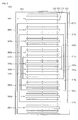
- FIG. 2A is a schematic view illustrating the electrode assembly in FIG. 1 .
- the electrode assembly 100 includes a first separator 110, a second separator 120, and a plurality of electrodes 130.
- the first separator 110 is wound in a direction (counterclockwise from the center outward when viewing the drawings).
- the first wound separator 110 includes a plurality of first stacked separator members 111a, 111b, 111c, and 111d and a plurality of first connectors 112a, 112b, 112c, and 112d to connect the first separator members 111a, 111b, 111c, and 111d to each other.
- Each of first separator members 111a, 111b, 111c, and 111d separates two electrodes 130 positioned at both sides thereof.
- An outer end 110c of the first separator 110 is attached to the outer circumferential surface 120d of the second separator 120 with a sealing tape 113.
- the first separator 110 has a plurality of fine porosities through which lithium ions migrating between the electrodes 130 pass.
- the first separator 110 may be made of a polymer such as polyethylene (PE) or polypropylene (PP).
- the second separator 120 and the first separator 110 are wound in a direction (counterclockwise from the center outward when viewing in the drawings) in alternating fashion.
- the second wound separator 120 includes a plurality of second stacked separator members 121a, 121b, 121c, and 121d and a plurality of second connectors 122a, 122b, 122c, and 122d to connect the second separator members 121a, 121b, 121c, and 121d to each other.
- the second separator members 121a, 121b, 121c, and 121d are positioned between the first separator members 111a, 111b, 111c, and 111d, and the second connectors 122a, 122b, 122c, and 122d are positioned between the first connectors 112a, 112b, 112c, and 112d. Due to this structure, the first separator members 111a, 111b, 111c, and 111d of the first separator 110 and the second separator members 121a, 121b, 121c, and 121d of the second separator 120 are alternatively positioned in a stack form.
- Each of the second separator members 121a, 121b, 121c, and 121d separates the two electrodes 130 positioned at both sides thereof.
- An inner surface 120a of the second separator member 121a positioned innermost among the second separator members 121a, 121b, 121c, and 121d faces to an inner surface 110a of the first separator member 111a positioned innermost among the first separator members 111a, 111b, 111c, and 111d.
- An outer end 120c of the second separator 120 is attached to outer circumferential surface 110d of the first separator 110 with a sealing tape 123.
- the second separator 120 has a plurality of fine porosities through which lithium ions migrating between electrodes 130 pass.
- the second separator 120 may be made of a polymer such as polyethylene PE or polypropylene (PP).
- the electrodes 130 are respectively positioned respectively between the first separator members 111a, 111b, 111c, and 111d of the first separator 110 and the second separator members 121a, 121b, 121c, and 121d of the second separator 120 one by one.
- the electrodes 130 are arranged such that respective two neighboring electrodes 130 interpose first separator 110 or the second separator 120 therebetween and the centers thereof are positioned at the same position. By doing so, all of the electrodes 130 are exactly arranged perpendicular to the separator members 111a, 111b, 111c, 111d, 121a, 121b, 121c, and 121d.
- a central electrode member 140a positioned between the first separator member 111a positioned innermost the first separator 110 and the second separator member 121a positioned innermost the second separator 120 is attached to the inner surface 120a of the second separator member 121a, and the remaining electrodes 130 are attached to outer surfaces of the first separator members 111a, 111b, 111c, and 111d or outer surfaces 120b of the second separator members 121a, 121b, 121c, and 121d.
- the electrodes 130 include a plurality of first electrode members 140a, 140b, 140c, 140d, and 140e and a plurality of second electrode members 150a, 150b, 150c, and 150d.
- the first electrode members 140a, 140b, 140c, 140d, and 140e and the second electrode members 150a, 150b, 150c, and 150d are alternatively positioned.
- Each of the first electrode members 140a, 140b, 140c, 140d, and 140e includes a positive electrode plate 141.
- the positive electrode plate 141 includes a positive electrode collector 142 and positive electrode active materials 143 coated on the both side of the positive electrode collector 142.
- the positive electrode collector 142 is generally made of an electrically conductive metal plate such as aluminum.
- the positive electrode collector 142 has a positive electrode tab 142a protruded outwardly without the positive electrode active material 143.
- the positive electrode tab 142a of the positive electrode plate 141 is welded to a positive terminal 160 protruded to the outside of the pouch case 20 by ultrasonic or resistance welding.
- the positive electrode active material 143 includes a layered lithium compound, an electrically conductive material to increase electric conductivity, and a binder to increase a binding force between the layered compound and the electrically conductive material.
- Each of the second electrode members 150a, 150b, 150c, and 150d has a negative electrode plate 151.
- the negative electrode plate 151 includes a negative electrode collector 152 and negative electrode active materials 153 coated on both sides of the negative electrode collector 152.
- the negative electrode collector 152 is generally made of an electrically conductive metal plate such as copper.
- the negative electrode collector 152 has a negative electrode tab 152a protruded outwardly without the negative electrode active material 153.
- the negative electrode tab 152a of the respective negative electrode plates 151 is welded to a negative terminal 170 protruded to the outside of the pouch case 20 by ultrasonic or resistance welding.
- the negative electrode active material 153 is prepared by mixing a carbon material such as graphite and a binder to increase a binding force between carbon particles.
- the positive electrode plate may have an area smaller than that of the negative electrode plate.
- the corresponding positive electrode plate may have an area larger than that of the negative electrode plate.
- FIG. 3 shows a process for manufacturing of the electrode assembly in FIG. 2A .
- the first separator 110 and the second separator 120 are respectively fed from the opposite sides of a winding position P.
- the first separator 110 is fed from left to right toward the winding position P when viewing the drawing.
- the first separator 110 has an inner surface 110a becoming the inside by winding and an outer surface 110b becoming an outer side opposite to the inner surface 110a by winding.
- the first separator 110 includes the electrodes 130 attached thereto.
- the electrodes 130 attached to the first separator 110 are respectively positioned on the outer surface 110b of the first separator 110 to be spaced apart from each other in the feeding direction of the first separator 110.
- First electrode members 140b and 140d and second electrode members 150a and 150c of the electrodes 130 are alternatively positioned on the outer surface 110b of the first separator 110.
- the electrode member 150a which is positioned on a firstly winding portion 110e of the electrodes 130 attached to the outer surface 110b of the first separator 110, becomes a second electrode member but the present invention is not limited thereto.
- the electrode member 150a may be a first electrode member.
- the second separator 120 is fed from right to left toward the winding position P when viewing the drawing.
- the second separator 120 has an inner surface 120a becoming the inside by winding and an outer surface 120b becoming an outer side opposite to the inner surface 120a by winding.
- the second separator 120 includes a plurality of electrode members 130 attached thereto.
- the electrodes 130 attached to the second separator 120 are respectively positioned on the outer surface 120b of the second separator 120 to be spaced apart from each other in the feeding direction of the second separator 120.
- First electrode members 140c and 140e and second electrode members 150b and 150d of the electrodes 130 are alternatively positioned on the outer surface 120b of the second separator 120.
- the electrode member 150b which is positioned on a firstly winding portion 120e of the electrodes 130 attached to the outer surface 120b of the second separator 120, becomes a second electrode member having the same polarity as that of the electrode member 150a.
- a central electrode member 140a is attached to the inner surface 120a of the second separator 120.
- the central electrode member 140a is positioned on the firstly winding portion 120e of the second separator to correspond to the second electrode member 150b.
- the central electrode member 140a becomes the first electrode member having polarity opposite to the polarity of the second electrode member 150b.
- the first electrode member 150a Before the winding, the first electrode member 150a is positioned above the central electrode member 140a at the winding position P by interposing the first separator 110 therebetween. By doing so, the first electrode member 150a, the central electrode member 140a, and the second electrode member 150b are sequentially arranged between the first separator 110 and the second separator 120 in a stacked form, respectively. In this state, the first electrode member 150a, the central electrode member 140a, and the second electrode member 150b are gripped and wound to form the electrode assembly 100 as shown in FIG. 2A .
- the electrode members 150a, 140a, and 150b are wound in the direction such that the electrode members 140b, 140c, 140d, 140e, 150a, 150b, 150c, and 150d except for the central electrode member 140a are positioned outside.
- the electrodes 130 may be fed during the winding, and the distance between the electrodes 130 may be easily adjusted to exactly arrange the electrodes 130 during the winding. In other words, as the winding is performing, the electrodes 130 are fed to the separators 110 and 120 such that the distance between the electrodes 130 is gradually increased.
- the electrodes 130 may be arranged at exact positions.
- FIGS. 4A, 4B and 2B First and second electrodes according to another embodiment of the present invention are illustrated in FIGS. 4A, 4B and 2B , respectively.
- a first electrode member 240 includes two positive electrode plates 241 and 242, a single negative electrode plate 243 positioned between the positive electrode plates 241 and 242, and two separators 244 and 245 respectively positioned between the negative electrode plate 243 and the positive electrode plates 241 and 242. Since the two positive electrode plates 241 and 242 are identical to the positive electrode plate 141 as shown in FIG. 2A and the negative electrode plate 243 is identical to the negative electrode plate 151 as shown in FIG. 2A , the detailed description thereof will be omitted. Fine porosities are formed in the separators 244 and 245, and lithium ions migrating between the electrode plates 241, 242, and 243 pass through the fine porosities.
- the separators 244 and 245 are made of a polymer such as polyethylene (PE) or polypropylene (PP).
- the second electrode member 250 includes two negative electrode plates 251 and 252, a positive electrode plate 253 positioned between the negative electrode plates 251 and 252, and two separators 254 and 255 respectively positioned between the positive electrode plate 253 and the two negative electrode plates 251 and 252. Since the negative electrode plates 251 and 252 are identical to the negative electrode plate 151 as shown in FIG. 2A and the positive electrode plate 253 is identical to the positive electrode plate 141 as shown in FIG. 2A , the detailed description thereof will be omitted. Fine porosities are formed in the separators 254 and 255, and lithium ions migrating between the electrode plates 251, 252, and 253 pass through the fine porosities.
- the separator 254 and 255 are made of a polymer such as polyethylene (PE) or polypropylene (PP).
- FIG. 2B illustrates another embodiment of an electrode assembly where the first electrode member 240 and the second electrode member 250 are alternately arranged into an electrode assembly with the separators 110 and 120 interposed therebetween in substantially the same manner as described above in conjunction with FIG. 2A . Since the arrangement of the electrode members 240, 250 and separators 110, 120 are substantially the same as the corresponding arrangement of the electrodes 140, 150 and separators 110, 120 in FIG. 2A , the detailed description thereof will be omitted.
- each of the first and second electrode members are made of three electrode plates, but the present invention is not limited thereto.
- the first and second electrode members may be made of more electrode plates. Any structure in which electrode plates having different polarities are alternatively positioned and another electrode plates having the same polarity are positioned at both sides of the alternatively positioned electrode plate may be allowed.
- FIG. 5 is a schematic view illustrating an electrode assembly according to another embodiment of the present invention.
- an electrode assembly 300 includes a first separator 310, a second separator 320, and a plurality of electrode members 330a, 330b, 330c, 330d, 330e, 330f, 330g, 330h, and 330i.
- first separator 310 and the second separator 320 are identical to those of the first separator 110 and the second separator 120, their detailed description will be omitted.
- the electrode members 330a, 330b, 330c, 330d, 330e, 330f, 330g, 330h, and 330i are respectively positioned between the first separators 311a, 311b, 311c, and 311d and the second separators 321a, 321b, 321c, and 321d one by one.
- Two neighboring electrode members of the electrode members 330a, 330b, 330c, 330d, 330e, 330f, 330g, 330h, and 330i are arranged at the same position to interpose the first separator 310 and the second separator 320.
- a central electrode member 330a of the electrode members 330a, 330b, 330c, 330d, 330e, 330f, 330g, 330h, and 330i which is positioned between a first separator member 311a a positioned at the innermost portion side of the first separator 310 and a second separator member 321a positioned at the innermost side of the second separator 320, is attached to an inner surface 320a of the second separator member 321a, and the other electrode members 330b, 330c, 330d, 330e, 330f, 330g, 330h, and 330i, except for the central electrode member 330a, is attached to outer surfaces 310b of the first separator members 311a, 311b, 311c, and 311d, or outer surfaces 320b of the second separator members 321a, 321b, 321c, and 321d.
- Each of the electrode members 330a, 330b, 330c, 330d, 330e, 330f, 330g, 330h, and 330i includes a positive electrode plate 332, a negative electrode plate 333, and a separator 331 positioned between the electrode plates 332 and 333. Fine porosities are formed in the separator 331 through which lithium ions migrating between the electrode plates 332 and 333 pass.
- the separator 331 may be made of a polymer such as polyethylene PE or polypropylene (PP).
- the positive electrode plates 332 is identical to the positive electrode plate 141 as shown in FIG. 2A
- the negative electrode plate 333 is identical to the negative electrode plate 151 as shown in FIG. 2B .
- the electrode members 330a, 330b, 330c, 330d, 330e, 330f, 330g, 330h, and 330i are formed such that electrode plates having different polarities face each other by interposing the first separators 310 or the second separators 320 therebetween.
- FIG. 6 A process of manufacturing the electrode assembly as shown in FIG. 5 is illustrated in FIG. 6 .
- the first separator 310 and the second separator 320 are respectively fed from the opposite sides of the winding position P to the winding position P.
- the first separator 310 is fed from left to right toward the winding position P when viewing the drawing.
- the first separator 310 has an inner surface 310a becoming the inside by winding and an outer surface 310b becoming an outer side opposite to the inner surface 310a by winding.
- the first separator 310 includes the electrode members 330b, 330d, and 330f attached thereto.
- the electrode members 330b, 330d, and 330f attached to the first separator 310 are respectively positioned on the outer surface 310b of the first separator 310 to be spaced apart from each other in the feeding direction of the first separator 310.
- the electrode members 330b, 330d, and 330f are attached to the outer surface 310b of the first separator 310 such that surfaces of the electrode members 330b, 330d, and 330f having opposite polarities alternatively contact the first separator 310.
- a negative electrode pate 333b of the electrode member 330b which is positioned on the firstly winding portion 310e among a plurality of electrode members 330b, 330d, and 330f attached to the outer surface 310b of the first separator 310, contacts the first separator 310, but the present invention is not limited thereto.
- a positive electrode pate 332b of the first electrode member 330b may contact the first separator 310.
- the second separator 320 is fed from right to left toward the winding position P when viewing the drawing.
- the second separator 320 has an inner surface 320a becoming an inside 320a by winding and an outer surface 320b becoming an outer side opposite to the inner surface 320a by winding.
- a plurality of electrode members 320c, 320e, and 320g are attached to the second separator 320.
- the electrode members 320c, 320e, and 320g attached to the second separator 320 are respectively positioned on the outer surface 320b of the second separator 320 to be spaced apart from each other in the feeding direction of the second separator 320.
- the electrode members 320c, 320e, and 320g are attached to the outer surface 320b of the second separator 320 such that surfaces of the electrode members 320c, 320e, and 320g having different polarities alternatively contact the second separator 320.
- a positive electrode plate 332c of the electrode member 330c which is positioned on the firstly winding portion 320e among a plurality of electrode members 320c, 320e, and 320g on the outer surface 320b of the second separator 320 contacts the second separator 320.
- a central electrode member 330a is attached to the inner surface 320a of the second separator 320.
- the central electrode member 330a is positioned on the firstly winding portion 320e of the second separator 320 to correspond to the second electrode member 330c.
- a negative electrode plate 333a of the central electrode member 330a contacts the second separator 320 so that each of the negative electrode plate 333a of the central electrode member 330a and the positive electrode plate 332c of the second electrode member 330c face each side by interposing the second separator 320 therebetween.
- the electrode member 330b Before the winding, the electrode member 330b is positioned above the central electrode member 330a at the winding position P by interposing the first separator 310 therebetween. By doing so, the electrode member 330b, the central electrode member 330a, and the electrode member 330c are sequentially arranged between the first separator 310 and the second separator 320 in a stacked form, respectively.
- the electrode member 330b, the central electrode member 330a, and the electrode member 330c are gripped and wound to form the electrode assembly 300 as shown in FIG. 5 .
- the winding is carried out in the direction where the electrode members 330b, 330c, 330d, 330e, 330f, 330g, 330h, and 330i except for the central electrode member 330a are positioned outside.
- the other structures and functions are the same as those of the embodiment in FIGS. 2 and 3 .
Landscapes
- Engineering & Computer Science (AREA)
- Manufacturing & Machinery (AREA)
- Chemical & Material Sciences (AREA)
- Chemical Kinetics & Catalysis (AREA)
- Electrochemistry (AREA)
- General Chemical & Material Sciences (AREA)
- Secondary Cells (AREA)
Abstract
Description
- The present invention relates to an electrode assembly for a battery and a method of manufacturing the same.
- A secondary battery is generally manufactured by accommodating an electrode assembly having a positive electrode plate, a negative electrode plate, and a separator interposed therebetween into an exterior case together with an electrolyte.
- In a high capacity secondary battery, a wound electrode assembly including a plurality of unit electrodes and separators is used. In this type electrode assembly, when the number of winding increases, it is not easy to exactly arrange the unit electrodes by interposing the separators therebetween.
- The present invention provides an electrode assembly having a structure in which entire unit electrodes are exactly arranged and a method of manufacturing the same.
- In accordance with an aspect of the present invention, there is provided an electrode assembly for a battery comprising: a plurality of first; a plurality of second electrodes wherein the plurality of first electrodes and the plurality of second electrodes are arranged into an alternating stack of electrodes; a first separator that is wound through the alternating stack of electrodes so that the first separator is interposed between adjacent first and second electrodes; and a second separator that is wound through the stack of electrodes so that the second separator is interposed between adjacent second and first electrodes and so that the second separator is interposed between adjacent portions of the first separator that are interposed between the adjacent first and second electrodes.
- According to another aspect of the present invention, there is provided a secondary battery including the electrode assembly as described above.
- Preferably, the first separator defines a plurality of stacked first separator members and the second separator defines a plurality of stacked second separator members and wherein the first and second stacked separator members are alternately interposed between first and second electrodes within the stack of electrodes.
- Preferably, at inner end portions of the first and second separators, an inner surface of the first separator and an inner surface of the second separator face each other.
- Preferably, inner ends of both the first and second separators are positioned at the innermost region of the electrode stack.
- Preferably, the first electrode comprises a positive electrode and the second electrode comprises a negative electrode.
- In some embodiments, the first electrodes and second electrodes are each comprised of at least one positive electrode and at least one negative electrode that are separated by discrete separators.
- In one embodiment, the first electrode comprises a first and a second positive electrode and a negative electrode that is interposed between the first and second positive electrodes wherein the discrete separators are interposed between the first and second positive electrodes and the negative electrode and the second electrodes comprise a first and a second negative electrode and a positive electrode that is interposed between the first and second negative electrodes wherein the discrete separators are interposed between the first and second negative electrodes and the positive electrode plate.
- Preferably, the first electrode comprises a positive electrode plate having a first and a second side wherein the positive electrode plate defines an electrode collector and wherein the first and the second side of the positive electrode plate are coated with a positive electrode active material and the second electrode comprises a negative electrode plate having a first and a second side wherein the negative electrode plate defines an electrode collector and wherein the first and the second side of the negative electrode plate are coated with a negative electrode active material.
- Preferably, the first separator is a continuous piece of material that is wound about the stack of electrodes in a first direction and the second separator is a continuous piece of material that is wound about the stack of electrodes in a first direction.
- Preferably, a centre electrode is positioned between the first separator and the second separator at inner ends of the separators.
- According to another aspect of the invention, there is provided method of forming an electrode assembly having an innermost region, comprising: providing a first separator having alternating first and second electrodes positioned thereon; providing a second separator having alternating first and second electrodes positioned thereon, with a first end of the first separator adjacent a first end of the second separator; winding the first and second separators together so the first ends of the first and second separator are positioned within the innermost region of the electrode assembly.
- Preferably, the method further comprises: winding the first and second separators such that the first and second separators are alternately interposed between the first and second electrodes.
- Preferably, before winding, the first ends of the first and second separators overlap each other such that an inner surface of the first separator and an inner surface of the second separator face each other at the innermost region of the electrode assembly.
- Preferably the electrodes on the first separator are positioned on an opposite side of the separator to the electrodes positioned on the second separator and a centre electrode is positioned between the separators at the overlapping portion. Preferably, the first electrodes are positive electrodes and the second electrodes are negative electrodes.
- Preferably, the first and second electrodes are each comprised of at least one positive electrode and at least one negative electrode that are separated by discrete separators.
- Preferably, the electrodes are positioned on the separators so that adjacent electrodes on the separators are spaced further apart from each other, the further the electrodes are positioned from the first ends of the separators.
- Hereinafter, embodiments of the present invention will be described in detail with reference to the accompanying drawings, in which.
-
FIG. 1 is a perspective view illustrating a secondary battery according to an embodiment of the present invention; -
FIG. 2A is a schematic view illustrating a first electrode assembly inFIG. 1 ; -
FIG 2B is a schematic view illustrating a second electrode assembly ofFIG. 1 ; -
FIG. 3 is a view illustrating a manufacturing process of the electrode assembly inFIG. 2A ; -
FIG. 4A is a schematic view illustrating a first electrode member of the electrode assembly as shown inFIG. 2B according to another embodiment of the present invention; -
FIG. 4B is a schematic view illustrating a second electrode member of the electrode assembly as shown inFIG. 2B according to another embodiment of the present invention; -
FIG. 5 is a schematic view illustrating the secondary battery inFIG. 1 according to another embodiment of the present invention; and -
FIG. 6 is a view illustrating a manufacturing process of the secondary battery inFIG. 5 . -
FIG. 1 is a perspective view illustrating a secondary battery including an electrode assembly according to an embodiment of the present invention. Referring toFIG. 1 , asecondary battery 10 is a pouch type secondary battery and includes apouch case 20 and anelectrode assembly 100 to be accommodated in thepouch case 20. - The
pouch case 20 includes abody 22 and acover 24. Thebody 22 includes anaccommodating portion 22a to accommodate theelectrode assembly 100 and a sealingmember 23 extending to the outside of theaccommodating portion 22a. Thecover 24 is integrally coupled to one side of the sealingmember 23. After theelectrode assembly 100 is accommodated in theaccommodating portion 22a of thebody 22, thebody 22 and thecover 24 contact closely with each other and then the sealingmember 23 is thermally welded. -
FIG. 2A is a schematic view illustrating the electrode assembly inFIG. 1 . Referring toFIGS. 1 and2A , theelectrode assembly 100 includes afirst separator 110, asecond separator 120, and a plurality ofelectrodes 130. - The
first separator 110 is wound in a direction (counterclockwise from the center outward when viewing the drawings). Thefirst wound separator 110 includes a plurality of first stackedseparator members first connectors first separator members first separator members electrodes 130 positioned at both sides thereof. Anouter end 110c of thefirst separator 110 is attached to the outercircumferential surface 120d of thesecond separator 120 with asealing tape 113. Thefirst separator 110 has a plurality of fine porosities through which lithium ions migrating between theelectrodes 130 pass. Thefirst separator 110 may be made of a polymer such as polyethylene (PE) or polypropylene (PP). - The
second separator 120 and thefirst separator 110 are wound in a direction (counterclockwise from the center outward when viewing in the drawings) in alternating fashion. Thesecond wound separator 120 includes a plurality of second stackedseparator members second connectors second separator members second separator members first separator members second connectors first connectors first separator members first separator 110 and thesecond separator members second separator 120 are alternatively positioned in a stack form. Each of thesecond separator members electrodes 130 positioned at both sides thereof. Aninner surface 120a of thesecond separator member 121a positioned innermost among thesecond separator members inner surface 110a of thefirst separator member 111a positioned innermost among thefirst separator members outer end 120c of thesecond separator 120 is attached to outercircumferential surface 110d of thefirst separator 110 with asealing tape 123. Thesecond separator 120 has a plurality of fine porosities through which lithium ions migrating betweenelectrodes 130 pass. Thesecond separator 120 may be made of a polymer such as polyethylene PE or polypropylene (PP). - The
electrodes 130 are respectively positioned respectively between thefirst separator members first separator 110 and thesecond separator members second separator 120 one by one. Theelectrodes 130 are arranged such that respective two neighboringelectrodes 130 interposefirst separator 110 or thesecond separator 120 therebetween and the centers thereof are positioned at the same position. By doing so, all of theelectrodes 130 are exactly arranged perpendicular to theseparator members central electrode member 140a positioned between thefirst separator member 111a positioned innermost thefirst separator 110 and thesecond separator member 121a positioned innermost thesecond separator 120 is attached to theinner surface 120a of thesecond separator member 121a, and the remainingelectrodes 130 are attached to outer surfaces of thefirst separator members outer surfaces 120b of thesecond separator members - The
electrodes 130 include a plurality offirst electrode members second electrode members first electrode members second electrode members first electrode members positive electrode plate 141. Thepositive electrode plate 141 includes apositive electrode collector 142 and positive electrodeactive materials 143 coated on the both side of thepositive electrode collector 142. Thepositive electrode collector 142 is generally made of an electrically conductive metal plate such as aluminum. Thepositive electrode collector 142 has apositive electrode tab 142a protruded outwardly without the positive electrodeactive material 143. Thepositive electrode tab 142a of thepositive electrode plate 141 is welded to apositive terminal 160 protruded to the outside of thepouch case 20 by ultrasonic or resistance welding. - The positive electrode
active material 143 includes a layered lithium compound, an electrically conductive material to increase electric conductivity, and a binder to increase a binding force between the layered compound and the electrically conductive material. - Each of the
second electrode members negative electrode plate 151. Thenegative electrode plate 151 includes anegative electrode collector 152 and negative electrodeactive materials 153 coated on both sides of thenegative electrode collector 152. Thenegative electrode collector 152 is generally made of an electrically conductive metal plate such as copper. Thenegative electrode collector 152 has anegative electrode tab 152a protruded outwardly without the negative electrodeactive material 153. Thenegative electrode tab 152a of the respectivenegative electrode plates 151 is welded to anegative terminal 170 protruded to the outside of thepouch case 20 by ultrasonic or resistance welding. The negative electrodeactive material 153 is prepared by mixing a carbon material such as graphite and a binder to increase a binding force between carbon particles. In this case, the positive electrode plate may have an area smaller than that of the negative electrode plate. Further, when tin oxide (SnO) or lithium titanium oxide (LTO) is used as the negative electrode active material, the corresponding positive electrode plate may have an area larger than that of the negative electrode plate. -
FIG. 3 shows a process for manufacturing of the electrode assembly inFIG. 2A . Referring toFIG. 3 , thefirst separator 110 and thesecond separator 120 are respectively fed from the opposite sides of a winding position P. - The
first separator 110 is fed from left to right toward the winding position P when viewing the drawing. Thefirst separator 110 has aninner surface 110a becoming the inside by winding and anouter surface 110b becoming an outer side opposite to theinner surface 110a by winding. Thefirst separator 110 includes theelectrodes 130 attached thereto. Theelectrodes 130 attached to thefirst separator 110 are respectively positioned on theouter surface 110b of thefirst separator 110 to be spaced apart from each other in the feeding direction of thefirst separator 110.First electrode members second electrode members electrodes 130 are alternatively positioned on theouter surface 110b of thefirst separator 110. In this embodiment of the present invention, theelectrode member 150a, which is positioned on a firstly windingportion 110e of theelectrodes 130 attached to theouter surface 110b of thefirst separator 110, becomes a second electrode member but the present invention is not limited thereto. Theelectrode member 150a may be a first electrode member. - The
second separator 120 is fed from right to left toward the winding position P when viewing the drawing. Thesecond separator 120 has aninner surface 120a becoming the inside by winding and anouter surface 120b becoming an outer side opposite to theinner surface 120a by winding. Thesecond separator 120 includes a plurality ofelectrode members 130 attached thereto. Theelectrodes 130 attached to thesecond separator 120 are respectively positioned on theouter surface 120b of thesecond separator 120 to be spaced apart from each other in the feeding direction of thesecond separator 120.First electrode members second electrode members electrodes 130 are alternatively positioned on theouter surface 120b of thesecond separator 120. In this embodiment of the present invention, theelectrode member 150b, which is positioned on a firstly windingportion 120e of theelectrodes 130 attached to theouter surface 120b of thesecond separator 120, becomes a second electrode member having the same polarity as that of theelectrode member 150a. Acentral electrode member 140a is attached to theinner surface 120a of thesecond separator 120. Thecentral electrode member 140a is positioned on the firstly windingportion 120e of the second separator to correspond to thesecond electrode member 150b. Thecentral electrode member 140a becomes the first electrode member having polarity opposite to the polarity of thesecond electrode member 150b. - Before the winding, the
first electrode member 150a is positioned above thecentral electrode member 140a at the winding position P by interposing thefirst separator 110 therebetween. By doing so, thefirst electrode member 150a, thecentral electrode member 140a, and thesecond electrode member 150b are sequentially arranged between thefirst separator 110 and thesecond separator 120 in a stacked form, respectively. In this state, thefirst electrode member 150a, thecentral electrode member 140a, and thesecond electrode member 150b are gripped and wound to form theelectrode assembly 100 as shown inFIG. 2A . Theelectrode members electrode members central electrode member 140a are positioned outside. Theelectrodes 130 may be fed during the winding, and the distance between theelectrodes 130 may be easily adjusted to exactly arrange theelectrodes 130 during the winding. In other words, as the winding is performing, theelectrodes 130 are fed to theseparators electrodes 130 is gradually increased. - Thus, the
electrodes 130 may be arranged at exact positions. - First and second electrodes according to another embodiment of the present invention are illustrated in
FIGS. 4A, 4B and2B , respectively. - Referring to
FIG. 4A , afirst electrode member 240 includes twopositive electrode plates negative electrode plate 243 positioned between thepositive electrode plates separators negative electrode plate 243 and thepositive electrode plates positive electrode plates positive electrode plate 141 as shown inFIG. 2A and thenegative electrode plate 243 is identical to thenegative electrode plate 151 as shown inFIG. 2A , the detailed description thereof will be omitted. Fine porosities are formed in theseparators electrode plates separators - Referring to
FIG. 4B , thesecond electrode member 250 includes twonegative electrode plates positive electrode plate 253 positioned between thenegative electrode plates separators positive electrode plate 253 and the twonegative electrode plates negative electrode plates negative electrode plate 151 as shown inFIG. 2A and thepositive electrode plate 253 is identical to thepositive electrode plate 141 as shown inFIG. 2A , the detailed description thereof will be omitted. Fine porosities are formed in theseparators electrode plates separator -
FIG. 2B illustrates another embodiment of an electrode assembly where thefirst electrode member 240 and thesecond electrode member 250 are alternately arranged into an electrode assembly with theseparators FIG. 2A . Since the arrangement of theelectrode members separators separators FIG. 2A , the detailed description thereof will be omitted. - In the embodiment of
FIGS. 4A, 4B and2B , each of the first and second electrode members are made of three electrode plates, but the present invention is not limited thereto. The first and second electrode members may be made of more electrode plates. Any structure in which electrode plates having different polarities are alternatively positioned and another electrode plates having the same polarity are positioned at both sides of the alternatively positioned electrode plate may be allowed. -
FIG. 5 is a schematic view illustrating an electrode assembly according to another embodiment of the present invention. Referring toFIG. 5 , anelectrode assembly 300 includes afirst separator 310, asecond separator 320, and a plurality ofelectrode members - Since structures and functions of the
first separator 310 and thesecond separator 320 are identical to those of thefirst separator 110 and thesecond separator 120, their detailed description will be omitted. - The
electrode members first separators second separators electrode members first separator 310 and thesecond separator 320. Acentral electrode member 330a of theelectrode members first separator member 311a a positioned at the innermost portion side of thefirst separator 310 and asecond separator member 321a positioned at the innermost side of thesecond separator 320, is attached to aninner surface 320a of thesecond separator member 321a, and theother electrode members central electrode member 330a, is attached toouter surfaces 310b of thefirst separator members outer surfaces 320b of thesecond separator members - Each of the
electrode members positive electrode plate 332, anegative electrode plate 333, and aseparator 331 positioned between theelectrode plates separator 331 through which lithium ions migrating between theelectrode plates separator 331 may be made of a polymer such as polyethylene PE or polypropylene (PP). Thepositive electrode plates 332 is identical to thepositive electrode plate 141 as shown inFIG. 2A , and thenegative electrode plate 333 is identical to thenegative electrode plate 151 as shown inFIG. 2B . Thus, the detailed description thereof will be omitted. Theelectrode members first separators 310 or thesecond separators 320 therebetween. - A process of manufacturing the electrode assembly as shown in
FIG. 5 is illustrated inFIG. 6 . Referring toFIG. 6 , thefirst separator 310 and thesecond separator 320 are respectively fed from the opposite sides of the winding position P to the winding position P. - The
first separator 310 is fed from left to right toward the winding position P when viewing the drawing. Thefirst separator 310 has aninner surface 310a becoming the inside by winding and anouter surface 310b becoming an outer side opposite to theinner surface 310a by winding. Thefirst separator 310 includes theelectrode members electrode members first separator 310 are respectively positioned on theouter surface 310b of thefirst separator 310 to be spaced apart from each other in the feeding direction of thefirst separator 310. Theelectrode members outer surface 310b of thefirst separator 310 such that surfaces of theelectrode members first separator 310. In this embodiment of the present invention, anegative electrode pate 333b of theelectrode member 330b, which is positioned on the firstly windingportion 310e among a plurality ofelectrode members outer surface 310b of thefirst separator 310, contacts thefirst separator 310, but the present invention is not limited thereto. Apositive electrode pate 332b of thefirst electrode member 330b may contact thefirst separator 310. - The
second separator 320 is fed from right to left toward the winding position P when viewing the drawing. Thesecond separator 320 has aninner surface 320a becoming an inside 320a by winding and anouter surface 320b becoming an outer side opposite to theinner surface 320a by winding. A plurality ofelectrode members 320c, 320e, and 320g are attached to thesecond separator 320. Theelectrode members 320c, 320e, and 320g attached to thesecond separator 320 are respectively positioned on theouter surface 320b of thesecond separator 320 to be spaced apart from each other in the feeding direction of thesecond separator 320. Theelectrode members 320c, 320e, and 320g are attached to theouter surface 320b of thesecond separator 320 such that surfaces of theelectrode members 320c, 320e, and 320g having different polarities alternatively contact thesecond separator 320. In this embodiment of the present invention, apositive electrode plate 332c of theelectrode member 330c, which is positioned on the firstly windingportion 320e among a plurality ofelectrode members 320c, 320e, and 320g on theouter surface 320b of thesecond separator 320 contacts thesecond separator 320. Acentral electrode member 330a is attached to theinner surface 320a of thesecond separator 320. Thecentral electrode member 330a is positioned on the firstly windingportion 320e of thesecond separator 320 to correspond to thesecond electrode member 330c. Anegative electrode plate 333a of thecentral electrode member 330a contacts thesecond separator 320 so that each of thenegative electrode plate 333a of thecentral electrode member 330a and thepositive electrode plate 332c of thesecond electrode member 330c face each side by interposing thesecond separator 320 therebetween. - Before the winding, the
electrode member 330b is positioned above thecentral electrode member 330a at the winding position P by interposing thefirst separator 310 therebetween. By doing so, theelectrode member 330b, thecentral electrode member 330a, and theelectrode member 330c are sequentially arranged between thefirst separator 310 and thesecond separator 320 in a stacked form, respectively. - In this state, the
electrode member 330b, thecentral electrode member 330a, and theelectrode member 330c are gripped and wound to form theelectrode assembly 300 as shown inFIG. 5 . The winding is carried out in the direction where theelectrode members central electrode member 330a are positioned outside. The other structures and functions are the same as those of the embodiment inFIGS. 2 and3 . - Although exemplary embodiments of the present invention have been described in detail hereinabove, it should be understood that many variations and modifications of the basic inventive concept herein described, which may appear to those skilled in the art, will still fall within the scope of the exemplary embodiments of the present invention as defined in the appended claims.
Claims (15)
- An electrode assembly for a battery comprising:a plurality of first electrodes (140a, 140b, 140c, 140d, 140e, 240, 330a, 330d, 330e, 330h, 330i);a plurality of second electrodes (150a, 150b, 150c, 150d, 150e, 250, 330b, 330c, 330f, 330g) wherein the plurality of first electrodes and the plurality of second electrodes are arranged into an alternating stack of electrodes (130);a first separator (110, 310) that is wound through the alternating stack of electrodes (130) so that the first separator (110, 310) is interposed between adjacent first and second electrodes; anda second separator (120, 320) that is wound through the stack of electrodes (130) so that the second separator (120, 320) is interposed between adjacent second and first electrodes and so that the second separator (120, 320) is interposed between adjacent portions of the first separator that are interposed between the adjacent first and second electrodes.
- The assembly of claim 1, wherein the first separator (110, 310) defines a plurality of stacked first separator members (111a, 111b, 111c, 111d, 311a, 311b, 311 c, 311 d) and the second separator defines a plurality of stacked second separator members (121a, 121b, 121c, 121d, 321a, 321b, 321c, 321d) and wherein the first and second stacked separator members are alternately interposed between first and second electrodes within the stack of electrodes.
- The assembly of claim 1 or 2, wherein, at inner end portions of the first and second separators, an inner surface (110a, 310a) of the first separator (110, 310) and an inner surface (120a, 320a) of the second separator (120, 320) face each other.
- The assembly of any one of the preceding claims, wherein inner ends of both the first and second separators (110, 310, 120, 320) are positioned at the innermost region of the electrode stack.
- The assembly of any one of the preceding claims, wherein the first electrode (140a, 140b, 140c, 140d, 140e, 240, 330a, 330d, 330e, 330h, 330i) comprises a positive electrode and the second electrode (150a, 150b, 150c, 150d, 150e, 250, 330b, 330c, 330f, 330g) comprises a negative electrode.
- The assembly of any one of the preceding claims, wherein the first electrodes (240, 330a, 330d, 330e, 330h, 330i) and second electrodes (250, 330b, 330c, 330f, 330g) are each comprised of at least one positive electrode and at least one negative electrode that are separated by discrete separators (244, 245, 254, 255, 331).
- The assembly of claim 6, wherein the first electrode (240) comprises a first and a second positive electrode (241, 242) and a negative electrode (243) that is interposed between the first and second positive electrodes (241, 242) wherein the discrete separators (244, 245) are interposed between the first and second positive electrodes (241, 242) and the negative electrode (243) and the second electrodes (250) comprise a first and a second negative electrode (251, 252) and a positive electrode (253) that is interposed between the first and second negative electrodes (251, 252) wherein the discrete separators (254, 255) are interposed between the first and second negative electrodes (251, 252) and the positive electrode plate (253).
- The assembly of any one of the preceding claims, wherein the first electrode comprises a positive electrode plate having a first and a second side wherein the positive electrode plate defines an electrode collector and wherein the first and the second side of the positive electrode plate are coated with a positive electrode active material and the second electrode comprises a negative electrode plate having a first and a second side wherein the negative electrode plate defines an electrode collector and wherein the first and the second side of the negative electrode plate are coated with a negative electrode active material.
- The assembly of any one of the preceding claims, wherein the first separator (110, 310) is a continuous piece of material that is wound about the stack of electrodes in a first direction and the second separator (120, 320) is a continuous piece of material that is wound about the stack of electrodes in a first direction.
- The assembly of any one of the preceding claims, wherein a centre electrode (140a, 330a) is positioned between the first separator (110, 310) and the second separator (120, 320) at inner ends of the separators.
- A method of forming an electrode assembly having an innermost region, comprising:providing a first separator (110, 310) having alternating first and second electrodes (150a, 140b, 150c, 140d, 330b, 330d, 330f) positioned thereon; providing a second separator (120, 320) having alternating first and second electrodes (150b, 140c, 150d, 140e, 330c, 330e, 330g) positioned thereon, with a first end of the first separator (110, 310) adjacent a first end of the second separator (120, 320);winding the first and second separators (110, 310, 120, 320) together so the first ends of the first and second separator (110, 310, 120, 320) are positioned within the innermost region of the electrode assembly.
- The method of claim 11, further comprising:winding the first and second separators (110, 310, 120, 320) such that the first and second separators (110, 310, 120, 320) are alternately interposed between the first and second electrodes.
- The method of claim 11 or 12, wherein, before winding, the first ends of the first and second separators overlap each other such that an inner surface (110a, 310a) of the first separator (110, 310) and an inner surface (120a, 320a) of the second separator (120, 320) face each other at the innermost region of the electrode assembly.
- The method of claim 13, wherein the electrodes on the first separator (110, 310) are positioned on an opposite side of the separator to the electrodes positioned on the second separator (120, 320) and a centre electrode (140a, 330a) is positioned between the separators at the overlapping portion.
- The method of any one of claims 11 to 14, wherein the electrodes are positioned on the separators so that adjacent electrodes on the separators (110, 310, 120, 320) are spaced further apart from each other, the further the electrodes are positioned from the first ends of the separators (110, 310, 120, 320).
Applications Claiming Priority (2)
| Application Number | Priority Date | Filing Date | Title |
|---|---|---|---|
| US18186209P | 2009-05-28 | 2009-05-28 | |
| US12/649,111 US20100304198A1 (en) | 2009-05-28 | 2009-12-29 | Electrode assembly for secondary battery and method of manufacturing the same |
Publications (2)
| Publication Number | Publication Date |
|---|---|
| EP2256853A1 true EP2256853A1 (en) | 2010-12-01 |
| EP2256853B1 EP2256853B1 (en) | 2016-03-30 |
Family
ID=42617390
Family Applications (1)
| Application Number | Title | Priority Date | Filing Date |
|---|---|---|---|
| EP10163099.4A Active EP2256853B1 (en) | 2009-05-28 | 2010-05-18 | Electrode assembly for a battery and a method of forming an electrode assembly |
Country Status (5)
| Country | Link |
|---|---|
| US (1) | US20100304198A1 (en) |
| EP (1) | EP2256853B1 (en) |
| JP (1) | JP5324521B2 (en) |
| KR (1) | KR101084889B1 (en) |
| CN (1) | CN101901930B (en) |
Cited By (4)
| Publication number | Priority date | Publication date | Assignee | Title |
|---|---|---|---|---|
| EP2683010A1 (en) * | 2012-07-04 | 2014-01-08 | Samsung SDI Co., Ltd. | Secondary battery comprising two electrode assemblies |
| EP2750241A4 (en) * | 2012-05-31 | 2015-01-21 | Lg Chemical Ltd | ELECTRODE ASSEMBLY HAVING LEVELED LEVELS AND BATTERY CELL, BATTERY PACK AND DEVICE COMPRISING SAME |
| EP2858165A4 (en) * | 2012-05-25 | 2015-11-25 | Lg Chemical Ltd | SAMPLE ELECTRODE ASSEMBLY AND BATTERY CELL, BATTERY PACK, AND DEVICE COMPRISING THE ELECTRODE ASSEMBLY |
| IT201700103755A1 (en) * | 2017-09-15 | 2019-03-15 | Manz Italy Srl | METHOD AND APPARATUS FOR ASSEMBLING ELECTRODES |
Families Citing this family (7)
| Publication number | Priority date | Publication date | Assignee | Title |
|---|---|---|---|---|
| US20110177383A1 (en) * | 2010-01-19 | 2011-07-21 | Lightening Energy | Battery cell module for modular battery with interleaving separator |
| JP4683505B1 (en) | 2010-12-14 | 2011-05-18 | 株式会社ワコム | Position indicator |
| TWI484681B (en) * | 2012-05-23 | 2015-05-11 | Lg化學股份有限公司 | Fabricating method of electrode assembly and electrochemical cell containing the same |
| KR101595643B1 (en) | 2013-02-15 | 2016-02-18 | 주식회사 엘지화학 | Electrode assembly and cell of polymer lithium secondary battery comprising the same |
| KR101791674B1 (en) | 2014-10-31 | 2017-10-30 | 주식회사 엘지화학 | Electrode Assembly Comprising Bi-cell and Full-Cell and Secondary Battery Having the Same |
| US11296370B2 (en) * | 2015-12-03 | 2022-04-05 | Eaglepicher Technologies, Llc | Battery having high thermal conductivity case |
| IT201600119013A1 (en) * | 2016-11-24 | 2018-05-24 | Manz Italy Srl | Production of Electrical Energy Storage Devices |
Citations (3)
| Publication number | Priority date | Publication date | Assignee | Title |
|---|---|---|---|---|
| EP1150371A2 (en) * | 2000-04-28 | 2001-10-31 | Matsushita Electric Industrial Co., Ltd. | Electrode plate unit and battery |
| WO2004068626A1 (en) * | 2003-01-27 | 2004-08-12 | Enerland Co., Ltd. | Stacked lithium secondary battery and its fabrication |
| WO2004097971A1 (en) * | 2003-04-25 | 2004-11-11 | Enerland Co. Ltd. | Stacked lithium secondary battery and its fabrication |
Family Cites Families (8)
| Publication number | Priority date | Publication date | Assignee | Title |
|---|---|---|---|---|
| JP3730491B2 (en) * | 1999-07-28 | 2006-01-05 | 三菱化学株式会社 | Battery having control electrode surface |
| KR100515572B1 (en) * | 2000-02-08 | 2005-09-20 | 주식회사 엘지화학 | Stacked electrochemical cell and method for preparing the same |
| SG103298A1 (en) * | 2000-06-16 | 2004-04-29 | Nisshin Spinning | Polymer battery and method of manufacture |
| US7332242B2 (en) * | 2000-09-01 | 2008-02-19 | Itochu Corporation | Lithium-based battery having extensible, ion-impermeable polymer covering on the battery container |
| US7396612B2 (en) * | 2003-07-29 | 2008-07-08 | Matsushita Electric Industrial Co., Ltd. | Lithium ion secondary battery |
| KR101209010B1 (en) * | 2007-04-26 | 2012-12-06 | 주식회사 엘지화학 | Stacking-Typed Electrode Assembly and Process of Preparing the Same |
| KR101065883B1 (en) * | 2009-10-15 | 2011-09-19 | 삼성에스디아이 주식회사 | A secondary battery comprising an electrode assembly for a secondary battery, a method of manufacturing the same, and an electrode assembly thereof |
| US8709637B2 (en) * | 2009-11-02 | 2014-04-29 | Samsung Sdi Co., Ltd. | Electrode assembly with centrally wound separator member |
-
2009
- 2009-12-29 US US12/649,111 patent/US20100304198A1/en not_active Abandoned
-
2010
- 2010-04-07 KR KR1020100031911A patent/KR101084889B1/en active Active
- 2010-05-13 CN CN201010178421.5A patent/CN101901930B/en active Active
- 2010-05-17 JP JP2010112995A patent/JP5324521B2/en active Active
- 2010-05-18 EP EP10163099.4A patent/EP2256853B1/en active Active
Patent Citations (3)
| Publication number | Priority date | Publication date | Assignee | Title |
|---|---|---|---|---|
| EP1150371A2 (en) * | 2000-04-28 | 2001-10-31 | Matsushita Electric Industrial Co., Ltd. | Electrode plate unit and battery |
| WO2004068626A1 (en) * | 2003-01-27 | 2004-08-12 | Enerland Co., Ltd. | Stacked lithium secondary battery and its fabrication |
| WO2004097971A1 (en) * | 2003-04-25 | 2004-11-11 | Enerland Co. Ltd. | Stacked lithium secondary battery and its fabrication |
Cited By (11)
| Publication number | Priority date | Publication date | Assignee | Title |
|---|---|---|---|---|
| EP2858165A4 (en) * | 2012-05-25 | 2015-11-25 | Lg Chemical Ltd | SAMPLE ELECTRODE ASSEMBLY AND BATTERY CELL, BATTERY PACK, AND DEVICE COMPRISING THE ELECTRODE ASSEMBLY |
| US9431679B2 (en) | 2012-05-25 | 2016-08-30 | Lg Chem, Ltd. | Electrode assembly having stepped portion, as well as battery cell, battery pack, and device including the electrode assembly |
| EP2750241A4 (en) * | 2012-05-31 | 2015-01-21 | Lg Chemical Ltd | ELECTRODE ASSEMBLY HAVING LEVELED LEVELS AND BATTERY CELL, BATTERY PACK AND DEVICE COMPRISING SAME |
| US9660296B2 (en) | 2012-05-31 | 2017-05-23 | Lg Chem, Ltd. | Electrode assembly having step, battery cell, battery pack and device including the same |
| EP2683010A1 (en) * | 2012-07-04 | 2014-01-08 | Samsung SDI Co., Ltd. | Secondary battery comprising two electrode assemblies |
| CN103531835A (en) * | 2012-07-04 | 2014-01-22 | 三星Sdi株式会社 | secondary battery |
| US9413029B2 (en) | 2012-07-04 | 2016-08-09 | Samsung Sdi Co., Ltd. | Secondary battery |
| CN103531835B (en) * | 2012-07-04 | 2019-04-30 | 三星Sdi株式会社 | Secondary battery |
| IT201700103755A1 (en) * | 2017-09-15 | 2019-03-15 | Manz Italy Srl | METHOD AND APPARATUS FOR ASSEMBLING ELECTRODES |
| WO2019053530A1 (en) * | 2017-09-15 | 2019-03-21 | Manz Italy S.R.L. | Method and apparatus for assembling electrodes |
| US12021198B2 (en) | 2017-09-15 | 2024-06-25 | Manz Italy S.R.L. | Method and apparatus for assembling electrodes |
Also Published As
| Publication number | Publication date |
|---|---|
| JP2010278002A (en) | 2010-12-09 |
| CN101901930A (en) | 2010-12-01 |
| EP2256853B1 (en) | 2016-03-30 |
| KR101084889B1 (en) | 2011-11-17 |
| CN101901930B (en) | 2014-11-12 |
| US20100304198A1 (en) | 2010-12-02 |
| KR20100129142A (en) | 2010-12-08 |
| JP5324521B2 (en) | 2013-10-23 |
Similar Documents
| Publication | Publication Date | Title |
|---|---|---|
| EP2256853B1 (en) | Electrode assembly for a battery and a method of forming an electrode assembly | |
| US11973177B2 (en) | Secondary battery and method for manufacturing the same | |
| KR102836930B1 (en) | Battery with tabless electrode | |
| EP2299522B1 (en) | Method of manufacturing electrode assembly for rechargeable battery | |
| EP3905417A1 (en) | Method for manufacturing electrode assembly, and electrode and secondary battery manufactured thereby | |
| US8815434B2 (en) | Electrode assembly for secondary battery with wound and folded separator portions and secondary battery having the same | |
| EP2487738B1 (en) | Electrode assembly and secondary battery using the same | |
| EP2312683B1 (en) | An electrode assembly for a secondary battery and a method of manufacturing an electrode assembly | |
| US8709637B2 (en) | Electrode assembly with centrally wound separator member | |
| CN112534624A (en) | Electrode assembly and secondary battery including the same | |
| EP3246979B1 (en) | Rechargeable battery | |
| EP2736102B1 (en) | Electrode assembly and rechargeable battery having the same | |
| KR20120061354A (en) | Electrochemical device having plural power characteristics | |
| CN116235362B (en) | Manufacturing methods for electrode components, battery cells, battery packs, and electrode components | |
| KR101192092B1 (en) | Stacking type electrode assembly and lithium ion secondary battery having the same | |
| US20200194763A1 (en) | Electrode assembly and method for manufacturing the same | |
| KR20210017086A (en) | Electrode-assembly and manufacturing method thereof | |
| JP7146386B2 (en) | Method for manufacturing electric storage element | |
| JP2023140177A (en) | Electrode body, storage element |
Legal Events
| Date | Code | Title | Description |
|---|---|---|---|
| PUAI | Public reference made under article 153(3) epc to a published international application that has entered the european phase |
Free format text: ORIGINAL CODE: 0009012 |
|
| 17P | Request for examination filed |
Effective date: 20100518 |
|
| AK | Designated contracting states |
Kind code of ref document: A1 Designated state(s): AL AT BE BG CH CY CZ DE DK EE ES FI FR GB GR HR HU IE IS IT LI LT LU LV MC MK MT NL NO PL PT RO SE SI SK SM TR |
|
| AX | Request for extension of the european patent |
Extension state: BA ME RS |
|
| 17Q | First examination report despatched |
Effective date: 20140218 |
|
| GRAJ | Information related to disapproval of communication of intention to grant by the applicant or resumption of examination proceedings by the epo deleted |
Free format text: ORIGINAL CODE: EPIDOSDIGR1 |
|
| GRAP | Despatch of communication of intention to grant a patent |
Free format text: ORIGINAL CODE: EPIDOSNIGR1 |
|
| INTG | Intention to grant announced |
Effective date: 20150929 |
|
| GRAS | Grant fee paid |
Free format text: ORIGINAL CODE: EPIDOSNIGR3 |
|
| GRAA | (expected) grant |
Free format text: ORIGINAL CODE: 0009210 |
|
| AK | Designated contracting states |
Kind code of ref document: B1 Designated state(s): AL AT BE BG CH CY CZ DE DK EE ES FI FR GB GR HR HU IE IS IT LI LT LU LV MC MK MT NL NO PL PT RO SE SI SK SM TR |
|
| REG | Reference to a national code |
Ref country code: GB Ref legal event code: FG4D |
|
| REG | Reference to a national code |
Ref country code: CH Ref legal event code: EP |
|
| REG | Reference to a national code |
Ref country code: AT Ref legal event code: REF Ref document number: 786268 Country of ref document: AT Kind code of ref document: T Effective date: 20160415 |
|
| REG | Reference to a national code |
Ref country code: IE Ref legal event code: FG4D |
|
| REG | Reference to a national code |
Ref country code: DE Ref legal event code: R096 Ref document number: 602010031587 Country of ref document: DE |
|
| REG | Reference to a national code |
Ref country code: FR Ref legal event code: PLFP Year of fee payment: 7 |
|
| REG | Reference to a national code |
Ref country code: LT Ref legal event code: MG4D |
|
| PG25 | Lapsed in a contracting state [announced via postgrant information from national office to epo] |
Ref country code: FI Free format text: LAPSE BECAUSE OF FAILURE TO SUBMIT A TRANSLATION OF THE DESCRIPTION OR TO PAY THE FEE WITHIN THE PRESCRIBED TIME-LIMIT Effective date: 20160330 Ref country code: GR Free format text: LAPSE BECAUSE OF FAILURE TO SUBMIT A TRANSLATION OF THE DESCRIPTION OR TO PAY THE FEE WITHIN THE PRESCRIBED TIME-LIMIT Effective date: 20160701 Ref country code: HR Free format text: LAPSE BECAUSE OF FAILURE TO SUBMIT A TRANSLATION OF THE DESCRIPTION OR TO PAY THE FEE WITHIN THE PRESCRIBED TIME-LIMIT Effective date: 20160330 Ref country code: NO Free format text: LAPSE BECAUSE OF FAILURE TO SUBMIT A TRANSLATION OF THE DESCRIPTION OR TO PAY THE FEE WITHIN THE PRESCRIBED TIME-LIMIT Effective date: 20160630 |
|
| REG | Reference to a national code |
Ref country code: NL Ref legal event code: MP Effective date: 20160330 |
|
| REG | Reference to a national code |
Ref country code: AT Ref legal event code: MK05 Ref document number: 786268 Country of ref document: AT Kind code of ref document: T Effective date: 20160330 |
|
| PG25 | Lapsed in a contracting state [announced via postgrant information from national office to epo] |
Ref country code: BE Free format text: LAPSE BECAUSE OF NON-PAYMENT OF DUE FEES Effective date: 20160531 Ref country code: SE Free format text: LAPSE BECAUSE OF FAILURE TO SUBMIT A TRANSLATION OF THE DESCRIPTION OR TO PAY THE FEE WITHIN THE PRESCRIBED TIME-LIMIT Effective date: 20160330 Ref country code: LV Free format text: LAPSE BECAUSE OF FAILURE TO SUBMIT A TRANSLATION OF THE DESCRIPTION OR TO PAY THE FEE WITHIN THE PRESCRIBED TIME-LIMIT Effective date: 20160330 Ref country code: LT Free format text: LAPSE BECAUSE OF FAILURE TO SUBMIT A TRANSLATION OF THE DESCRIPTION OR TO PAY THE FEE WITHIN THE PRESCRIBED TIME-LIMIT Effective date: 20160330 |
|
| PG25 | Lapsed in a contracting state [announced via postgrant information from national office to epo] |
Ref country code: NL Free format text: LAPSE BECAUSE OF FAILURE TO SUBMIT A TRANSLATION OF THE DESCRIPTION OR TO PAY THE FEE WITHIN THE PRESCRIBED TIME-LIMIT Effective date: 20160330 |
|
| PG25 | Lapsed in a contracting state [announced via postgrant information from national office to epo] |
Ref country code: IS Free format text: LAPSE BECAUSE OF FAILURE TO SUBMIT A TRANSLATION OF THE DESCRIPTION OR TO PAY THE FEE WITHIN THE PRESCRIBED TIME-LIMIT Effective date: 20160730 Ref country code: EE Free format text: LAPSE BECAUSE OF FAILURE TO SUBMIT A TRANSLATION OF THE DESCRIPTION OR TO PAY THE FEE WITHIN THE PRESCRIBED TIME-LIMIT Effective date: 20160330 Ref country code: PL Free format text: LAPSE BECAUSE OF FAILURE TO SUBMIT A TRANSLATION OF THE DESCRIPTION OR TO PAY THE FEE WITHIN THE PRESCRIBED TIME-LIMIT Effective date: 20160330 |
|
| PG25 | Lapsed in a contracting state [announced via postgrant information from national office to epo] |
Ref country code: SM Free format text: LAPSE BECAUSE OF FAILURE TO SUBMIT A TRANSLATION OF THE DESCRIPTION OR TO PAY THE FEE WITHIN THE PRESCRIBED TIME-LIMIT Effective date: 20160330 Ref country code: AT Free format text: LAPSE BECAUSE OF FAILURE TO SUBMIT A TRANSLATION OF THE DESCRIPTION OR TO PAY THE FEE WITHIN THE PRESCRIBED TIME-LIMIT Effective date: 20160330 Ref country code: CZ Free format text: LAPSE BECAUSE OF FAILURE TO SUBMIT A TRANSLATION OF THE DESCRIPTION OR TO PAY THE FEE WITHIN THE PRESCRIBED TIME-LIMIT Effective date: 20160330 Ref country code: PT Free format text: LAPSE BECAUSE OF FAILURE TO SUBMIT A TRANSLATION OF THE DESCRIPTION OR TO PAY THE FEE WITHIN THE PRESCRIBED TIME-LIMIT Effective date: 20160801 Ref country code: ES Free format text: LAPSE BECAUSE OF FAILURE TO SUBMIT A TRANSLATION OF THE DESCRIPTION OR TO PAY THE FEE WITHIN THE PRESCRIBED TIME-LIMIT Effective date: 20160330 Ref country code: SK Free format text: LAPSE BECAUSE OF FAILURE TO SUBMIT A TRANSLATION OF THE DESCRIPTION OR TO PAY THE FEE WITHIN THE PRESCRIBED TIME-LIMIT Effective date: 20160330 Ref country code: RO Free format text: LAPSE BECAUSE OF FAILURE TO SUBMIT A TRANSLATION OF THE DESCRIPTION OR TO PAY THE FEE WITHIN THE PRESCRIBED TIME-LIMIT Effective date: 20160330 |
|
| PG25 | Lapsed in a contracting state [announced via postgrant information from national office to epo] |
Ref country code: LU Free format text: LAPSE BECAUSE OF FAILURE TO SUBMIT A TRANSLATION OF THE DESCRIPTION OR TO PAY THE FEE WITHIN THE PRESCRIBED TIME-LIMIT Effective date: 20160518 Ref country code: IT Free format text: LAPSE BECAUSE OF FAILURE TO SUBMIT A TRANSLATION OF THE DESCRIPTION OR TO PAY THE FEE WITHIN THE PRESCRIBED TIME-LIMIT Effective date: 20160330 Ref country code: BE Free format text: LAPSE BECAUSE OF FAILURE TO SUBMIT A TRANSLATION OF THE DESCRIPTION OR TO PAY THE FEE WITHIN THE PRESCRIBED TIME-LIMIT Effective date: 20160330 |
|
| REG | Reference to a national code |
Ref country code: CH Ref legal event code: PL |
|
| REG | Reference to a national code |
Ref country code: DE Ref legal event code: R097 Ref document number: 602010031587 Country of ref document: DE |
|
| PG25 | Lapsed in a contracting state [announced via postgrant information from national office to epo] |
Ref country code: CH Free format text: LAPSE BECAUSE OF NON-PAYMENT OF DUE FEES Effective date: 20160531 Ref country code: DK Free format text: LAPSE BECAUSE OF FAILURE TO SUBMIT A TRANSLATION OF THE DESCRIPTION OR TO PAY THE FEE WITHIN THE PRESCRIBED TIME-LIMIT Effective date: 20160330 Ref country code: LI Free format text: LAPSE BECAUSE OF NON-PAYMENT OF DUE FEES Effective date: 20160531 |
|
| PLBE | No opposition filed within time limit |
Free format text: ORIGINAL CODE: 0009261 |
|
| STAA | Information on the status of an ep patent application or granted ep patent |
Free format text: STATUS: NO OPPOSITION FILED WITHIN TIME LIMIT |
|
| REG | Reference to a national code |
Ref country code: IE Ref legal event code: MM4A |
|
| 26N | No opposition filed |
Effective date: 20170103 |
|
| REG | Reference to a national code |
Ref country code: FR Ref legal event code: PLFP Year of fee payment: 8 |
|
| PG25 | Lapsed in a contracting state [announced via postgrant information from national office to epo] |
Ref country code: IE Free format text: LAPSE BECAUSE OF NON-PAYMENT OF DUE FEES Effective date: 20160518 Ref country code: SI Free format text: LAPSE BECAUSE OF FAILURE TO SUBMIT A TRANSLATION OF THE DESCRIPTION OR TO PAY THE FEE WITHIN THE PRESCRIBED TIME-LIMIT Effective date: 20160330 |
|
| REG | Reference to a national code |
Ref country code: FR Ref legal event code: PLFP Year of fee payment: 9 |
|
| PG25 | Lapsed in a contracting state [announced via postgrant information from national office to epo] |
Ref country code: HU Free format text: LAPSE BECAUSE OF FAILURE TO SUBMIT A TRANSLATION OF THE DESCRIPTION OR TO PAY THE FEE WITHIN THE PRESCRIBED TIME-LIMIT; INVALID AB INITIO Effective date: 20100518 Ref country code: CY Free format text: LAPSE BECAUSE OF FAILURE TO SUBMIT A TRANSLATION OF THE DESCRIPTION OR TO PAY THE FEE WITHIN THE PRESCRIBED TIME-LIMIT Effective date: 20160330 |
|
| PG25 | Lapsed in a contracting state [announced via postgrant information from national office to epo] |
Ref country code: MT Free format text: LAPSE BECAUSE OF NON-PAYMENT OF DUE FEES Effective date: 20160531 Ref country code: MK Free format text: LAPSE BECAUSE OF FAILURE TO SUBMIT A TRANSLATION OF THE DESCRIPTION OR TO PAY THE FEE WITHIN THE PRESCRIBED TIME-LIMIT Effective date: 20160330 Ref country code: TR Free format text: LAPSE BECAUSE OF FAILURE TO SUBMIT A TRANSLATION OF THE DESCRIPTION OR TO PAY THE FEE WITHIN THE PRESCRIBED TIME-LIMIT Effective date: 20160330 Ref country code: MC Free format text: LAPSE BECAUSE OF FAILURE TO SUBMIT A TRANSLATION OF THE DESCRIPTION OR TO PAY THE FEE WITHIN THE PRESCRIBED TIME-LIMIT Effective date: 20160330 |
|
| PG25 | Lapsed in a contracting state [announced via postgrant information from national office to epo] |
Ref country code: BG Free format text: LAPSE BECAUSE OF FAILURE TO SUBMIT A TRANSLATION OF THE DESCRIPTION OR TO PAY THE FEE WITHIN THE PRESCRIBED TIME-LIMIT Effective date: 20160330 |
|
| PG25 | Lapsed in a contracting state [announced via postgrant information from national office to epo] |
Ref country code: AL Free format text: LAPSE BECAUSE OF FAILURE TO SUBMIT A TRANSLATION OF THE DESCRIPTION OR TO PAY THE FEE WITHIN THE PRESCRIBED TIME-LIMIT Effective date: 20160330 |
|
| P01 | Opt-out of the competence of the unified patent court (upc) registered |
Effective date: 20230528 |
|
| PGFP | Annual fee paid to national office [announced via postgrant information from national office to epo] |
Ref country code: DE Payment date: 20250429 Year of fee payment: 16 |
|
| PGFP | Annual fee paid to national office [announced via postgrant information from national office to epo] |
Ref country code: GB Payment date: 20250501 Year of fee payment: 16 |
|
| PGFP | Annual fee paid to national office [announced via postgrant information from national office to epo] |
Ref country code: FR Payment date: 20250508 Year of fee payment: 16 |