EP2256530A1 - Protected fiber optic assemblies and methods for forming the same - Google Patents
Protected fiber optic assemblies and methods for forming the same Download PDFInfo
- Publication number
- EP2256530A1 EP2256530A1 EP10005316A EP10005316A EP2256530A1 EP 2256530 A1 EP2256530 A1 EP 2256530A1 EP 10005316 A EP10005316 A EP 10005316A EP 10005316 A EP10005316 A EP 10005316A EP 2256530 A1 EP2256530 A1 EP 2256530A1
- Authority
- EP
- European Patent Office
- Prior art keywords
- fiber optic
- optic connector
- protecting material
- optic assembly
- connector
- Prior art date
- Legal status (The legal status is an assumption and is not a legal conclusion. Google has not performed a legal analysis and makes no representation as to the accuracy of the status listed.)
- Withdrawn
Links
- 239000000835 fiber Substances 0.000 title claims abstract description 102
- 238000000034 method Methods 0.000 title claims 6
- 230000000712 assembly Effects 0.000 title abstract description 9
- 238000000429 assembly Methods 0.000 title abstract description 9
- 239000000463 material Substances 0.000 claims abstract description 71
- 230000001681 protective effect Effects 0.000 claims abstract description 61
- 230000004888 barrier function Effects 0.000 claims abstract description 23
- KAATUXNTWXVJKI-UHFFFAOYSA-N cypermethrin Chemical compound CC1(C)C(C=C(Cl)Cl)C1C(=O)OC(C#N)C1=CC=CC(OC=2C=CC=CC=2)=C1 KAATUXNTWXVJKI-UHFFFAOYSA-N 0.000 claims abstract description 20
- 239000006229 carbon black Substances 0.000 claims abstract description 10
- 239000000428 dust Substances 0.000 claims description 8
- 239000013307 optical fiber Substances 0.000 claims description 4
- 229920001343 polytetrafluoroethylene Polymers 0.000 claims description 4
- 239000004810 polytetrafluoroethylene Substances 0.000 claims description 4
- 238000004519 manufacturing process Methods 0.000 claims 1
- 230000006750 UV protection Effects 0.000 abstract description 4
- 239000011888 foil Substances 0.000 abstract description 3
- 238000009472 formulation Methods 0.000 description 13
- 239000000203 mixture Substances 0.000 description 13
- 230000003287 optical effect Effects 0.000 description 7
- 230000007613 environmental effect Effects 0.000 description 4
- 239000000499 gel Substances 0.000 description 4
- 230000004224 protection Effects 0.000 description 3
- 229920006362 Teflon® Polymers 0.000 description 2
- BGYHLZZASRKEJE-UHFFFAOYSA-N [3-[3-(3,5-ditert-butyl-4-hydroxyphenyl)propanoyloxy]-2,2-bis[3-(3,5-ditert-butyl-4-hydroxyphenyl)propanoyloxymethyl]propyl] 3-(3,5-ditert-butyl-4-hydroxyphenyl)propanoate Chemical compound CC(C)(C)C1=C(O)C(C(C)(C)C)=CC(CCC(=O)OCC(COC(=O)CCC=2C=C(C(O)=C(C=2)C(C)(C)C)C(C)(C)C)(COC(=O)CCC=2C=C(C(O)=C(C=2)C(C)(C)C)C(C)(C)C)COC(=O)CCC=2C=C(C(O)=C(C=2)C(C)(C)C)C(C)(C)C)=C1 BGYHLZZASRKEJE-UHFFFAOYSA-N 0.000 description 2
- 239000000356 contaminant Substances 0.000 description 2
- 238000012986 modification Methods 0.000 description 2
- 230000004048 modification Effects 0.000 description 2
- 239000004014 plasticizer Substances 0.000 description 2
- 229920002635 polyurethane Polymers 0.000 description 2
- 239000004814 polyurethane Substances 0.000 description 2
- 238000007789 sealing Methods 0.000 description 2
- 229920002121 Hydroxyl-terminated polybutadiene Polymers 0.000 description 1
- 229920002633 Kraton (polymer) Polymers 0.000 description 1
- 239000004677 Nylon Substances 0.000 description 1
- 239000005062 Polybutadiene Substances 0.000 description 1
- 230000002745 absorbent Effects 0.000 description 1
- 239000002250 absorbent Substances 0.000 description 1
- 239000004760 aramid Substances 0.000 description 1
- 229920003235 aromatic polyamide Polymers 0.000 description 1
- 230000005540 biological transmission Effects 0.000 description 1
- 230000000295 complement effect Effects 0.000 description 1
- 238000011109 contamination Methods 0.000 description 1
- PWWSSIYVTQUJQQ-UHFFFAOYSA-N distearyl thiodipropionate Chemical compound CCCCCCCCCCCCCCCCCCOC(=O)CCSCCC(=O)OCCCCCCCCCCCCCCCCCC PWWSSIYVTQUJQQ-UHFFFAOYSA-N 0.000 description 1
- 239000002360 explosive Substances 0.000 description 1
- 230000002401 inhibitory effect Effects 0.000 description 1
- 230000013011 mating Effects 0.000 description 1
- 239000002184 metal Substances 0.000 description 1
- 239000002480 mineral oil Substances 0.000 description 1
- 235000010446 mineral oil Nutrition 0.000 description 1
- 229920001778 nylon Polymers 0.000 description 1
- 239000003921 oil Substances 0.000 description 1
- 229920002857 polybutadiene Polymers 0.000 description 1
- -1 polytetrafluoroethylene Polymers 0.000 description 1
- 239000003381 stabilizer Substances 0.000 description 1
- 239000000126 substance Substances 0.000 description 1
- 239000012974 tin catalyst Substances 0.000 description 1
Images

Classifications
-
- G—PHYSICS
- G02—OPTICS
- G02B—OPTICAL ELEMENTS, SYSTEMS OR APPARATUS
- G02B6/00—Light guides; Structural details of arrangements comprising light guides and other optical elements, e.g. couplings
- G02B6/24—Coupling light guides
- G02B6/36—Mechanical coupling means
- G02B6/38—Mechanical coupling means having fibre to fibre mating means
- G02B6/3807—Dismountable connectors, i.e. comprising plugs
- G02B6/3833—Details of mounting fibres in ferrules; Assembly methods; Manufacture
- G02B6/3847—Details of mounting fibres in ferrules; Assembly methods; Manufacture with means preventing fibre end damage, e.g. recessed fibre surfaces
- G02B6/3849—Details of mounting fibres in ferrules; Assembly methods; Manufacture with means preventing fibre end damage, e.g. recessed fibre surfaces using mechanical protective elements, e.g. caps, hoods, sealing membranes
-
- Y—GENERAL TAGGING OF NEW TECHNOLOGICAL DEVELOPMENTS; GENERAL TAGGING OF CROSS-SECTIONAL TECHNOLOGIES SPANNING OVER SEVERAL SECTIONS OF THE IPC; TECHNICAL SUBJECTS COVERED BY FORMER USPC CROSS-REFERENCE ART COLLECTIONS [XRACs] AND DIGESTS
- Y10—TECHNICAL SUBJECTS COVERED BY FORMER USPC
- Y10T—TECHNICAL SUBJECTS COVERED BY FORMER US CLASSIFICATION
- Y10T29/00—Metal working
- Y10T29/49—Method of mechanical manufacture
- Y10T29/49826—Assembling or joining
Definitions
- the present disclosure relates generally to fiber optic assemblies that provide environmental protection until needed in the field. More specifieally, the disclosure relates to fiber optic assemblies such as fiber optic connectors having a protective material thereover that is removable.
- Fiber optic communication networks are experiencing explosive growth. In just a few years, the transmission of optical communication signals for voice, video, data, and the like has risen. Moreover, the future growth of fiber optical networks is necessary because subscribers are still demanding more bandwidth. To accommodate the bandwidth demand, network operators are investing in and installing optical networks to route optical fibers toward the subscriber. However, not all of the connections of the optical network are made when the fiber optic assemblies are installed. For instance, the network operator may route fiber optic assemblies for an entire neighborhood even though only a fraction of the subscribers sign-up for service. Instead, the network operator will make the optical connections when the subscriber sighs-up for service.
- the optical fibers within the fiber optic cables are protected from environmental effects by a cable jacket, a duct, or other like structure.
- the fiber optic connectors at the end of the cable typically include a dust cap for protecting the ferrule and its mating end face from dust, damage, and contamination.
- the fiber optic dust caps can allow for the ingress of moisture and/or other contaminants that can affect the optical performance of the connection.
- the dust cap does not protect the rest of the fiber optic connector from damage.
- the disclosure relates to fiber optic assemblies having a protecting material encapsulating a portion of the fiber optic connector for protecting the same in the field until needed by the craft.
- the fiber optic assembly includes a protective barrier such as a tape, foil, or the like disposed about the fiber optic connector.
- the fiber optic assembly includes structure for removing the protecting material such as a ripcord or a notch in the protecting material. Additionally, the protecting material may include carbon black for providing UV protection.
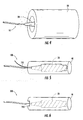
- FIG. 1 is a schematic view of a fiber optic assembly having a fiber optic connector
- FIG. 2 is a view of the fiber optic assembly of FIG. 1 having a protective barrier being applied about a portion of the fiber optic connector;
- FIG. 3 is a view of the fiber optic assembly of FIG. 1 having a protective material encapsulating a portion of the fiber optic connector;
- FIG. 4 is a view showing a fiber optic connector placed into a mold for forming a protective material therearound;
- FIG. 5 is a view of a fiber optic assembly having a protective material for protecting the same with a ripcord extending therefrom for aiding in the removal of the protective material;
- FIG. 6 is a view of fiber optic assembly having a protective material with a notch formed therein for aiding in the removal of the same.
- FIG. 1 is a schematic view of a fiber optic assembly 10 having a fiber optic cable 11 and a fiber optic connector 20.
- Fiber optic assembly 10 can include any suitable fiber optic cable and/or fiber optic connector.
- fiber optic cable 11 includes at least one optical fiber (not visible) and a cable jacket, but may include other cable components such as strength members, water-blocking or water-swelling substances, or other suitable components.
- Fiber optic connector 20 includes a connector housing 22, a ferrule 24 (not visible) and a dust cap 26. Additionally, the fiber optic connector 20 can include other components such as a boot, a spring for biasing the ferrule forward, a crimp band to secure strength members of the fiber optic cable, and/or other suitable components as known in the art.
- a protecting material encapsulates a portion of the fiber optic connector, thereby inhibiting the ingress of moisture and/or other contaminants that can affect the optical performance of the fiber optic connector.
- a protective barrier is disposed between a portion of the fiber optic connector and the protecting material.
- FIG. 2 is a view of the fiber optic assembly 10 having an optional protective barrier 30 being applied about a portion of the fiber optic connector 20 before the protecting material is applied over the same.
- the protective barrier 30 can be any suitable material and/or structure and is used for providing a barrier between the fiber optic connector 20 and the protecting material (applied afterward) that encapsulates a portion of the fiber optic connector.
- the protective barrier 30 may be formed from any suitable material such as Teflon®, paper, foil, shrink-wrap, or the like.
- protective barrier 30 is a tape wrapped about a portion of the fiber optic connector 20 as shown, but other structures such as a small bag-like structure or the like are possible to provide a protective barrier.
- the protective barrier is a polytetrafluoroethylene (PTFE) tape (i.e., Teflon® tape) that is wrapped directly over the fiber optic connector (including the dust cap). Moreover, the tape can be wrapped about fiber optic connector 20 in any suitable orientation.
- the PTFE tape easily conforms to the fiber optic connector and may be easily and cleanly removed by the craft when access to the fiber optic connector is desired.
- the protective barrier 30 covers the entire fiber optic connector, but it may cover less than the entire fiber optic connector 20 .
- FIG. 3 is a view of the fiber optic assembly 10 having a protective material 40 encapsulating at least a portion of the fiber optic connector 20 (shown in dashed lines) for protecting the same.
- Protective material 40 may be applied directly over a portion of the fiber optic connector 20 or over a protective barrier 30 as shown. If the protective barrier 30 is omitted, the protective material used should preferably strip cleanly from the fiber optic connector 20 and not leave any residue thereon for the craft to clean.
- Protective material 40 can have any suitable shape about a portion of fiber optic connector 20. Since the protective material provides robust environmental protection it is a rugged yet easily removable material so that no tools are required by the craft for removing the same.
- protective material 40 includes carbon black, thereby providing a degree of UV protection to the same; however, it is possible to practice the concepts disclosed with materials that do not include carbon black.
- variations of protective material 40 may have any suitable amount of carbon black such as 3%, 5 %, 10%, or more of carbon black for providing UV protection.
- the first protective material 40 is a polyurethane based two-part gel that cures in about twenty minutes after mixing. The cure time for this first material may be reduced when the temperature is elevated.
- the formulation for the first material is listed below:
- MDI prepolymer 100 Hydroxyl-terminated polybutadiene 106 Plasticizer (naphthenic oil Nytex 5110) 292 Tin catalyst 0.1 Carbon black 12.5 Moisture absorbent (zeolithe T) 1.12 Irganox 1010 0.1
- the MDI prepolymer has a percentage NCO of approximately 3.8% and the 1-ydroxyl-terminated polybutadiene has an OH content of about 0.85 mmol/gram and a viscosity of about 8000 cps at 23° C for the first protective material formulation.
- the plasticizer has a viscosity of 110 cSt at 40° C.
- this particular formulation provides excellent sealing characteristics and is easily fractured and removed (i.e.,peeled) from the fiber optic assembly by hand without the use of tools. Additionally, this first formulation may be cleanly removed without leaving an observable residue.
- other suitable polyurethane based two-part gel formulations are possible.
- a thermally-reversible gel (liquefies and solidifies as a function of temperature) may be used.
- the formulation for a second first protective material 40 is listed below:
- Kraton G1650 40 Mineral Oil 100 Irganox 1010 0.1 DSTDP (stabilizer) 0.08 Carbon black 3.5
- This second formulation provides good sealing characteristics and is easily fractured and removed (i.e.,peeled) from the fiber optic assembly by hand without the use of tools. Additionally, this second formulation may be cleanly removed without leaving an observable residue.
- other suitable gels formulations are possible.
- the two formulations disclosed herein are merely explanatory and many other material formulations are possible depending the desired characteristics.
- FIG. 4 depicts the fiber optic connector 20 of fiber optic assembly 10 placed into an exemplary mold 50 for forming the protective material 40 therearound.
- Mold 50 can have any suitable shape and may include suitable structure for positioning the fiber optic connector 20 therein. In other words, the mold may have structure for proper placement of the fiber optic connector within the mold so that fiber optic connector is not too close to an outer surface of the protective material.
- mold 50 is depicted for a single fiber optic assembly, other embodiments of the mold can be a gang mold for forming several the protective material about several fiber optic assemblies at once.
- FIG. 5 depicts a fiber optic assembly 100 having the protective material 40 encapsulating a portion of a fiber optic connector 20 (not visible) that is similar to fiber optic assembly 10, but that further includes a ripcord 110.
- Ripcord 110 enables the removal of the protective material and/or protective barrier by craft by pulling ripcord 110 to tear through the same.
- Ripcord 110 may be formed from any suitable material have the necessary strength. Examples of materials for the ripcord 110 include aramid yarns, metal wire, nylon, etc.
- ripcord 110 extends outward of protective material so that the craft may grip the same and pull the ripcord 110 through the protective material and/or the protective barrier. Additionally, ripcord 110 can be positioned over a portion of the fiber optic connector 20 as shown (i.e., over the front portion) so it tears the protective material rather than being pulled from the protective material.
- Fiber optic structures can have other structures for aiding in the removal of the protective material and/or protective barrier.
- FIG. 6 depicts a fiber optic assembly 200 having a protective material 40 with one or more notches 210 formed therein for aiding in the removal of the protective material. Consequently, the craft can separate (i.e., initiate a fracture) of the protective material 40 by applying a force at the notches 210 .
- the one or more notches 210 may be formed at any suitable portion of protective material. For instance, complementary notches may be located about 180 degrees apart on the sides so that the craft may begin separating the protective material at either side. In other embodiments, the notch 210 may be located at the rear of the protective material.
- the notches are preferably located where the craft can easily initiate a fracture of the protective material 40 to remove the same. It will be apparent to those skilled in the art that various modifications and variations can be made without departing from the spirit and scope of the invention. Thus, it is intended that the present invention cover the modifications and variations provided they come within the scope of the appended claims and their equivalents.
Landscapes
- Physics & Mathematics (AREA)
- General Physics & Mathematics (AREA)
- Optics & Photonics (AREA)
- Mechanical Coupling Of Light Guides (AREA)
- Light Guides In General And Applications Therefor (AREA)
Abstract
Fiber optic assemblies are disclosed that include a protecting material that encapsulates a portion of a fiber optic connector for protecting the same in the field until needed by the craft. In one embodiment, the fiber optic assembly includes a protective barrier such as a tape, foil, or the like disposed about the fiber optic connector. In other embodiments, the fiber optic assembly includes structure for removing the protecting material such as a ripcord or a notch in the protecting material. Additionally, the protecting material may include carbon black for providing UV protection.
Description
- The present disclosure relates generally to fiber optic assemblies that provide environmental protection until needed in the field. More specifieally, the disclosure relates to fiber optic assemblies such as fiber optic connectors having a protective material thereover that is removable.
- Fiber optic communication networks are experiencing explosive growth. In just a few years, the transmission of optical communication signals for voice, video, data, and the like has soared. Moreover, the future growth of fiber optical networks is necessary because subscribers are still demanding more bandwidth. To accommodate the bandwidth demand, network operators are investing in and installing optical networks to route optical fibers toward the subscriber. However, not all of the connections of the optical network are made when the fiber optic assemblies are installed. For instance, the network operator may route fiber optic assemblies for an entire neighborhood even though only a fraction of the subscribers sign-up for service. Instead, the network operator will make the optical connections when the subscriber sighs-up for service.
- The optical fibers within the fiber optic cables are protected from environmental effects by a cable jacket, a duct, or other like structure. The fiber optic connectors at the end of the cable typically include a dust cap for protecting the ferrule and its mating end face from dust, damage, and contamination. However, the fiber optic dust caps can allow for the ingress of moisture and/or other contaminants that can affect the optical performance of the connection. Moreover, the dust cap does not protect the rest of the fiber optic connector from damage. Thus, there is an unresolved need to protect fiber optic connectors that are not initially connected, but still allow for quick and easy connection by the craft when desired.
- The disclosure relates to fiber optic assemblies having a protecting material encapsulating a portion of the fiber optic connector for protecting the same in the field until needed by the craft. In one embodiment, the fiber optic assembly includes a protective barrier such as a tape, foil, or the like disposed about the fiber optic connector. In other embodiments, the fiber optic assembly includes structure for removing the protecting material such as a ripcord or a notch in the protecting material. Additionally, the protecting material may include carbon black for providing UV protection.
- Additional features and advantages are set forth in the detailed description that follows, and in part will be readily apparent to those skilled in the art from that description or recognized by practicing the concepts described herein, including the detailed description that follows, the claims, and the appended drawings. It is to be understood that both the foregoing general description and the following detailed description present exemplary embodiments, and are intended to provide an overview or framework for understanding the nature and character of the invention as it is claimed. The accompanying drawings are included to provide a further understanding of the concepts, and are incorporated into and constitute a part of this specification. The drawings illustrate various embodiments, and together with the detailed description, serve to explain the principles and operations thereof.
- These and other features, aspects and advantages are better understood when the following detailed description is read with reference to the accompanying drawings, in which:
-
FIG. 1 is a schematic view of a fiber optic assembly having a fiber optic connector; -
FIG. 2 is a view of the fiber optic assembly ofFIG. 1 having a protective barrier being applied about a portion of the fiber optic connector; -
FIG. 3 is a view of the fiber optic assembly ofFIG. 1 having a protective material encapsulating a portion of the fiber optic connector; -
FIG. 4 is a view showing a fiber optic connector placed into a mold for forming a protective material therearound; -
FIG. 5 is a view of a fiber optic assembly having a protective material for protecting the same with a ripcord extending therefrom for aiding in the removal of the protective material; and -
FIG. 6 is a view of fiber optic assembly having a protective material with a notch formed therein for aiding in the removal of the same. - Reference is now made to preferred embodiments, examples of which are illustrated in the accompanying drawings. Whenever possible, the same or similar reference numbers and symbols are used throughout the drawings to refer to the same or similar parts.
-
FIG. 1 is a schematic view of a fiberoptic assembly 10 having a fiberoptic cable 11 and a fiberoptic connector 20. Fiberoptic assembly 10 can include any suitable fiber optic cable and/or fiber optic connector. By way of example, fiberoptic cable 11 includes at least one optical fiber (not visible) and a cable jacket, but may include other cable components such as strength members, water-blocking or water-swelling substances, or other suitable components. Fiberoptic connector 20 includes aconnector housing 22, a ferrule 24 (not visible) and adust cap 26. Additionally, the fiberoptic connector 20 can include other components such as a boot, a spring for biasing the ferrule forward, a crimp band to secure strength members of the fiber optic cable, and/or other suitable components as known in the art. The concepts disclosed herein protect a portion of the fiber optic connector by providing environmental protection until it is needed in the field. In one embodiment, a protecting material encapsulates a portion of the fiber optic connector, thereby inhibiting the ingress of moisture and/or other contaminants that can affect the optical performance of the fiber optic connector. In another embodiment, a protective barrier is disposed between a portion of the fiber optic connector and the protecting material. -
FIG. 2 is a view of the fiberoptic assembly 10 having an optionalprotective barrier 30 being applied about a portion of the fiberoptic connector 20 before the protecting material is applied over the same. Theprotective barrier 30 can be any suitable material and/or structure and is used for providing a barrier between the fiberoptic connector 20 and the protecting material (applied afterward) that encapsulates a portion of the fiber optic connector. By way of example, theprotective barrier 30 may be formed from any suitable material such as Teflon®, paper, foil, shrink-wrap, or the like. In this embodiment,protective barrier 30 is a tape wrapped about a portion of the fiberoptic connector 20 as shown, but other structures such as a small bag-like structure or the like are possible to provide a protective barrier. In one advantageous embodiment, the protective barrier is a polytetrafluoroethylene (PTFE) tape (i.e., Teflon® tape) that is wrapped directly over the fiber optic connector (including the dust cap). Moreover, the tape can be wrapped about fiberoptic connector 20 in any suitable orientation. The PTFE tape easily conforms to the fiber optic connector and may be easily and cleanly removed by the craft when access to the fiber optic connector is desired. Preferably, theprotective barrier 30 covers the entire fiber optic connector, but it may cover less than the entire fiberoptic connector 20. -
FIG. 3 is a view of the fiberoptic assembly 10 having aprotective material 40 encapsulating at least a portion of the fiber optic connector 20 (shown in dashed lines) for protecting the same.Protective material 40 may be applied directly over a portion of the fiberoptic connector 20 or over aprotective barrier 30 as shown. If theprotective barrier 30 is omitted, the protective material used should preferably strip cleanly from the fiberoptic connector 20 and not leave any residue thereon for the craft to clean.Protective material 40 can have any suitable shape about a portion of fiberoptic connector 20. Since the protective material provides robust environmental protection it is a rugged yet easily removable material so that no tools are required by the craft for removing the same. Additionally, advantageous embodiments ofprotective material 40 include carbon black, thereby providing a degree of UV protection to the same; however, it is possible to practice the concepts disclosed with materials that do not include carbon black. By way of example, variations ofprotective material 40 may have any suitable amount of carbon black such as 3%, 5 %, 10%, or more of carbon black for providing UV protection. - Any suitable material may be used as
protective material 40, but it should not bond to theprotective barrier 30 or the fiberoptic assembly 10. Moreover, suitable materials will not "leak" inside the fiber optic connector. By way of example, two differentprotective materials 40 are disclosed herein. The firstprotective material 40 is a polyurethane based two-part gel that cures in about twenty minutes after mixing. The cure time for this first material may be reduced when the temperature is elevated. The formulation for the first material is listed below: -
MDI prepolymer 100 Hydroxyl-terminated polybutadiene 106 Plasticizer (naphthenic oil Nytex 5110) 292 Tin catalyst 0.1 Carbon black 12.5 Moisture absorbent (zeolithe T) 1.12 Irganox 1010 0.1 - In particular, the MDI prepolymer has a percentage NCO of approximately 3.8% and the 1-ydroxyl-terminated polybutadiene has an OH content of about 0.85 mmol/gram and a viscosity of about 8000 cps at 23° C for the first protective material formulation. Additionally, the plasticizer has a viscosity of 110 cSt at 40° C. When cured, this particular formulation provides excellent sealing characteristics and is easily fractured and removed (i.e.,peeled) from the fiber optic assembly by hand without the use of tools. Additionally, this first formulation may be cleanly removed without leaving an observable residue. Of course, other suitable polyurethane based two-part gel formulations are possible.
- Likewise, other classes of materials are possible for use as the protective material. By way of example, a thermally-reversible gel (liquefies and solidifies as a function of temperature) may be used. The formulation for a second first
protective material 40 is listed below: -
Kraton G1650 40 Mineral Oil 100 Irganox 1010 0.1 DSTDP (stabilizer) 0.08 Carbon black 3.5 - This second formulation provides good sealing characteristics and is easily fractured and removed (i.e.,peeled) from the fiber optic assembly by hand without the use of tools. Additionally, this second formulation may be cleanly removed without leaving an observable residue. Of course, other suitable gels formulations are possible. The two formulations disclosed herein are merely explanatory and many other material formulations are possible depending the desired characteristics.
-
FIG. 4 depicts thefiber optic connector 20 offiber optic assembly 10 placed into anexemplary mold 50 for forming theprotective material 40 therearound.Mold 50 can have any suitable shape and may include suitable structure for positioning thefiber optic connector 20 therein. In other words, the mold may have structure for proper placement of the fiber optic connector within the mold so that fiber optic connector is not too close to an outer surface of the protective material. Althoughmold 50 is depicted for a single fiber optic assembly, other embodiments of the mold can be a gang mold for forming several the protective material about several fiber optic assemblies at once. - Additionally, fiber optic assemblies disclosed herein can include structure for aiding the removal of the protective material and/or protective barrier.
FIG. 5 depicts afiber optic assembly 100 having theprotective material 40 encapsulating a portion of a fiber optic connector 20 (not visible) that is similar tofiber optic assembly 10, but that further includes aripcord 110.Ripcord 110 enables the removal of the protective material and/or protective barrier by craft by pullingripcord 110 to tear through the same.Ripcord 110 may be formed from any suitable material have the necessary strength. Examples of materials for theripcord 110 include aramid yarns, metal wire, nylon, etc. As shown, a portion ofripcord 110 extends outward of protective material so that the craft may grip the same and pull theripcord 110 through the protective material and/or the protective barrier. Additionally,ripcord 110 can be positioned over a portion of thefiber optic connector 20 as shown (i.e., over the front portion) so it tears the protective material rather than being pulled from the protective material. - Fiber optic structures can have other structures for aiding in the removal of the protective material and/or protective barrier.
FIG. 6 depicts afiber optic assembly 200 having aprotective material 40 with one ormore notches 210 formed therein for aiding in the removal of the protective material. Consequently, the craft can separate (i.e., initiate a fracture) of theprotective material 40 by applying a force at thenotches 210. Moreover, the one ormore notches 210 may be formed at any suitable portion of protective material. For instance, complementary notches may be located about 180 degrees apart on the sides so that the craft may begin separating the protective material at either side. In other embodiments, thenotch 210 may be located at the rear of the protective material. In any event, the notches are preferably located where the craft can easily initiate a fracture of theprotective material 40 to remove the same.
It will be apparent to those skilled in the art that various modifications and variations can be made without departing from the spirit and scope of the invention. Thus, it is intended that the present invention cover the modifications and variations provided they come within the scope of the appended claims and their equivalents.
Claims (15)
- A fiber optic assembly, comprising:a fiber optic connector having at least one ferrule with at least one optical fiber attached to the ferrule; anda protecting material encapsulating a portion of the fiber optic connector for protecting the same.
- The fiber optic assembly of claim 2, further including a dust cap.
- The fiber optic assembly of claims 1 or 2, wherein the fiber optic assembly further includes a fiber optic cable.
- The fiber optic assembly of claims 1-3, wherein a protective barrier is disposed between a portion of the fiber optic connector and the protecting material.
- The fiber optic assembly of claim 4, wherein the protective barrier is a tape.
- The fiber optic assembly of claims 1-5, wherein the protecting material includes carbon black.
- The fiber optic assembly of claims 1-6, further including a ripcord for removing the protecting material.
- The fiber optic assembly of claims 1-7, wherein the protecting material has a notch formed therein for aiding in removal of the protecting material.
- The fiber optic assembly of claims 1-8, further including a PTFE tape wrapped about a portion of the fiber optic connector.
- A-method of making a fiber optic assembly comprising the steps of:providing a fiber optic connector; andencapsulating a portion of the fiber optic connector with a protecting material.
- The method of claim 10, further including the step of placing a protective barrier about a portion of the fiber optic connector.
- The method of claim 11. wherein the protective barrier is a tape.
- The method of claims 10-12, the fiber optic connector further including a dust cap.
- The method of claims 10-13, wherein the protecting material includes carbon black.
- The method of claims 10-14, wherein the fiber optic assembly includes a fiber optic cable.
Applications Claiming Priority (2)
| Application Number | Priority Date | Filing Date | Title |
|---|---|---|---|
| US18213109P | 2009-05-29 | 2009-05-29 | |
| US12/550,922 US20100303425A1 (en) | 2009-05-29 | 2009-08-31 | Protected Fiber Optic Assemblies and Methods for Forming the Same |
Publications (1)
| Publication Number | Publication Date |
|---|---|
| EP2256530A1 true EP2256530A1 (en) | 2010-12-01 |
Family
ID=42271956
Family Applications (1)
| Application Number | Title | Priority Date | Filing Date |
|---|---|---|---|
| EP10005316A Withdrawn EP2256530A1 (en) | 2009-05-29 | 2010-05-21 | Protected fiber optic assemblies and methods for forming the same |
Country Status (4)
| Country | Link |
|---|---|
| US (1) | US20100303425A1 (en) |
| EP (1) | EP2256530A1 (en) |
| CN (1) | CN101907756A (en) |
| AU (1) | AU2010202071A1 (en) |
Families Citing this family (13)
| Publication number | Priority date | Publication date | Assignee | Title |
|---|---|---|---|---|
| WO2010138700A1 (en) * | 2009-05-29 | 2010-12-02 | Corning Cable Systems Llc | Dust cap assembly for sealing an optical fiber ferrule and methods thereof |
| ES2703235T3 (en) | 2011-11-23 | 2019-03-07 | Adc Telecommunications Inc | Fiber optic multi-fiber connector |
| CN104364686B (en) | 2012-02-07 | 2016-11-16 | 泰科电子瑞侃有限公司 | Cable termination assembly and method for adapter |
| CA2864886A1 (en) | 2012-02-20 | 2013-08-29 | Adc Telecommunications, Inc. | Fiber optic connector, fiber optic connector and cable assembly, and methods for manufacturing |
| US8998503B2 (en) | 2012-05-16 | 2015-04-07 | Corning Cable Systems Llc | Fiber optic connector and bonded cover |
| US8939654B2 (en) | 2012-09-27 | 2015-01-27 | Adc Telecommunications, Inc. | Ruggedized multi-fiber fiber optic connector with sealed dust cap |
| US9411110B2 (en) | 2013-02-06 | 2016-08-09 | Corning Optical Communications LLC | Fiber optic connector cover and fiber optic assembly including same |
| US9720185B2 (en) | 2014-05-23 | 2017-08-01 | Commscope Technologies Llc | Systems and method for processing optical cable assemblies |
| US9784924B2 (en) | 2014-06-30 | 2017-10-10 | Ultra Communications, Inc. | Fiber optic end-face transparent protector |
| US10429564B2 (en) * | 2014-07-09 | 2019-10-01 | Sunoptic Technologies Llc | Fiberoptic lightguide and method of manufacture |
| USD800660S1 (en) | 2015-06-05 | 2017-10-24 | Corning Optical Communications LLC | Fiber optic connector |
| USD800659S1 (en) | 2015-06-05 | 2017-10-24 | Corning Optical Communications LLC | Fiber optic connector |
| US11796742B1 (en) | 2020-04-24 | 2023-10-24 | Carlisle Interconnect Technologies, Inc. | Protective seal assembly for connector mating interface |
Citations (2)
| Publication number | Priority date | Publication date | Assignee | Title |
|---|---|---|---|---|
| US6261006B1 (en) * | 1999-09-24 | 2001-07-17 | Amphenol Corporation | Environmental sealing for fiber optic cable assemblies |
| US20070036487A1 (en) * | 2005-08-15 | 2007-02-15 | Barbara Grzegorzewska | Industrial optical fiber connector assembly |
Family Cites Families (27)
| Publication number | Priority date | Publication date | Assignee | Title |
|---|---|---|---|---|
| GB8709071D0 (en) * | 1987-04-15 | 1987-05-20 | Bp Chem Int Ltd | Insulation for fibre optic cable |
| US5182785A (en) * | 1991-10-10 | 1993-01-26 | W. L. Gore & Associates, Inc. | High-flex optical fiber coil cable |
| US5293442A (en) * | 1992-07-15 | 1994-03-08 | W. L. Gore & Associates, Inc. | Crush-resistant high-strength buffered optical waveguide fiber cable |
| US5412749A (en) * | 1993-10-26 | 1995-05-02 | W. L. Gore & Associates, Inc. | Dual fiber optic illumination bundle |
| US5675686A (en) * | 1995-07-05 | 1997-10-07 | W. L. Gore & Associates, Inc. | Buffer material for optical signal transmission media |
| US6487345B1 (en) * | 2000-01-12 | 2002-11-26 | Fitel Usa Corp. | Communication cable having reduced jacket shrinkage |
| US6547448B2 (en) * | 2001-05-15 | 2003-04-15 | The Boeing Company | Embeddable fiber optic connector and associated method |
| US6547450B2 (en) * | 2001-06-27 | 2003-04-15 | Fitel Usa Corp. | Quick-release dust cap for an optical plug |
| JP3720790B2 (en) * | 2002-04-18 | 2005-11-30 | 川崎重工業株式会社 | Method for manufacturing structure in which optical transmission medium is embedded |
| US6775444B1 (en) * | 2003-02-28 | 2004-08-10 | Corning Cable Systems Llc | Fiber optic assemblies and methods of making the same |
| US7088893B2 (en) * | 2003-11-26 | 2006-08-08 | Corning Cable Systems Llc | Pre-connectorized fiber optic distribution cable having multifiber connector |
| US7186038B2 (en) * | 2003-12-29 | 2007-03-06 | Adc Telecommunications, Inc. | Telecommunications connector protective device |
| US7242841B2 (en) * | 2005-02-28 | 2007-07-10 | Corning Cable Systems, Llc | Cross-connect fiber optic cables and associated cross-connect sections |
| US7203404B2 (en) * | 2005-02-28 | 2007-04-10 | Corning Cable Systems, Llc. | Loose tube fiber optic cables having at least one access location |
| US7272283B2 (en) * | 2005-11-01 | 2007-09-18 | Corning Cable Systems, Llc. | Distribution fiber optic cables for fiber to the subscriber applications |
| US7403685B2 (en) * | 2006-10-13 | 2008-07-22 | Adc Telecommunications, Inc. | Overmold zip strip |
| US7900225B2 (en) * | 2007-02-20 | 2011-03-01 | Google, Inc. | Association of ads with tagged audiovisual content |
| US8103646B2 (en) * | 2007-03-13 | 2012-01-24 | Microsoft Corporation | Automatic tagging of content based on a corpus of previously tagged and untagged content |
| WO2008123994A1 (en) * | 2007-04-03 | 2008-10-16 | Corning Cable Systems Llc | Attachment structure allowing movement and protection of a tether of a cable assembly |
| CN201063065Y (en) * | 2007-07-16 | 2008-05-21 | 何玫 | Composite inserting core for optical fiber connector |
| US8254684B2 (en) * | 2008-01-02 | 2012-08-28 | Yahoo! Inc. | Method and system for managing digital photos |
| US20090228492A1 (en) * | 2008-03-10 | 2009-09-10 | Verizon Data Services Inc. | Apparatus, system, and method for tagging media content |
| US20100029326A1 (en) * | 2008-07-30 | 2010-02-04 | Jonathan Bergstrom | Wireless data capture and sharing system, such as image capture and sharing of digital camera images via a wireless cellular network and related tagging of images |
| US20100076976A1 (en) * | 2008-09-06 | 2010-03-25 | Zlatko Manolov Sotirov | Method of Automatically Tagging Image Data |
| US8167504B2 (en) * | 2008-12-11 | 2012-05-01 | Tyco Electronics Corporation | Fiber optic multi dwelling unit deployment apparatus including a seamed protection jacket |
| US20100161631A1 (en) * | 2008-12-19 | 2010-06-24 | Microsoft Corporation | Techniques to share information about tags and documents across a computer network |
| KR101950997B1 (en) * | 2009-01-28 | 2019-02-21 | 삼성전자주식회사 | Method for managing contents with contents tag and apparatus thereof |
-
2009
- 2009-08-31 US US12/550,922 patent/US20100303425A1/en not_active Abandoned
-
2010
- 2010-05-21 EP EP10005316A patent/EP2256530A1/en not_active Withdrawn
- 2010-05-21 AU AU2010202071A patent/AU2010202071A1/en not_active Abandoned
- 2010-05-31 CN CN2010101915885A patent/CN101907756A/en active Pending
Patent Citations (2)
| Publication number | Priority date | Publication date | Assignee | Title |
|---|---|---|---|---|
| US6261006B1 (en) * | 1999-09-24 | 2001-07-17 | Amphenol Corporation | Environmental sealing for fiber optic cable assemblies |
| US20070036487A1 (en) * | 2005-08-15 | 2007-02-15 | Barbara Grzegorzewska | Industrial optical fiber connector assembly |
Non-Patent Citations (1)
| Title |
|---|
| ANDERS SJÖGREN ET AL: "Manufacturing technique for embedding detachable fiber-optic connections in aircraft composite components; Technique for embedding detachable fiber-optic connections", SMART MATERIALS AND STRUCTURES, IOP PUBLISHING LTD., BRISTOL, GB LNKD- DOI:10.1088/0964-1726/9/6/316, vol. 9, no. 6, 1 December 2000 (2000-12-01), pages 855 - 858, XP020071426, ISSN: 0964-1726 * |
Also Published As
| Publication number | Publication date |
|---|---|
| CN101907756A (en) | 2010-12-08 |
| AU2010202071A1 (en) | 2010-12-16 |
| US20100303425A1 (en) | 2010-12-02 |
Similar Documents
| Publication | Publication Date | Title |
|---|---|---|
| EP2256530A1 (en) | Protected fiber optic assemblies and methods for forming the same | |
| JP5188713B2 (en) | Shielded wire with drain wire waterproof structure and drain wire waterproof method | |
| US6899467B2 (en) | Fiber optic plug and receptacle assembly | |
| EP2920627B1 (en) | Optical fiber / electrical composite cable assembly with sealed breakout kit | |
| US6261006B1 (en) | Environmental sealing for fiber optic cable assemblies | |
| US9618718B2 (en) | Universal remote radio unit bird armored fiber optic cable assembly | |
| EP2715418B1 (en) | Molded fiber optic cable furcation assemblies, and related fiber optic components, assemblies, and methods | |
| US5042904A (en) | Communications cable and method having a talk path in an enhanced cable jacket | |
| EP2920632B1 (en) | Shielded electrical conductor furcation assembly | |
| WO2007103437A2 (en) | Reinforcing breakout closure with sealing potting material on either end thereof at a mid-span location along a distribution cable | |
| US20100086266A1 (en) | Splice of Fiber Optic Cables | |
| WO2007103439A2 (en) | Mid-span breakout with helical fiber routing | |
| EP4030208B1 (en) | Waterproof optical connector plug for outdoor field assembly, and method for manufacturing same | |
| EP2862015A1 (en) | Universal remote radio unit fiber optic cable assembly | |
| EP1872164B1 (en) | Optical fiber repair apparatus with adjustable guide member and methods for using the same | |
| US10054741B2 (en) | Fiber optic enclosure assembly | |
| WO2023129696A1 (en) | Protective sleeve configured to be tool-lessly removed from a cable assembly | |
| AU2016215668B2 (en) | Universal remote radio unit bird armored fiber optic cable assembly | |
| US11977268B2 (en) | Fiber optic cable assemblies having exposable cable legs for supporting multiple deployment scenarios | |
| KR20080003412U (en) | Optical connector box for home subscriber | |
| JPS63180914A (en) | Terminal part for composite cable | |
| JPS63290106A (en) | Laying method for composite cable |
Legal Events
| Date | Code | Title | Description |
|---|---|---|---|
| PUAI | Public reference made under article 153(3) epc to a published international application that has entered the european phase |
Free format text: ORIGINAL CODE: 0009012 |
|
| AK | Designated contracting states |
Kind code of ref document: A1 Designated state(s): AL AT BE BG CH CY CZ DE DK EE ES FI FR GB GR HR HU IE IS IT LI LT LU LV MC MK MT NL NO PL PT RO SE SI SK SM TR |
|
| AX | Request for extension of the european patent |
Extension state: BA ME RS |
|
| 17P | Request for examination filed |
Effective date: 20110601 |
|
| STAA | Information on the status of an ep patent application or granted ep patent |
Free format text: STATUS: THE APPLICATION IS DEEMED TO BE WITHDRAWN |
|
| 18D | Application deemed to be withdrawn |
Effective date: 20141202 |