EP2256509A2 - Method and system to measure and represent the measured value of a limit in terms of another measurement in a signal measurement system - Google Patents
Method and system to measure and represent the measured value of a limit in terms of another measurement in a signal measurement system Download PDFInfo
- Publication number
- EP2256509A2 EP2256509A2 EP10250930A EP10250930A EP2256509A2 EP 2256509 A2 EP2256509 A2 EP 2256509A2 EP 10250930 A EP10250930 A EP 10250930A EP 10250930 A EP10250930 A EP 10250930A EP 2256509 A2 EP2256509 A2 EP 2256509A2
- Authority
- EP
- European Patent Office
- Prior art keywords
- slew rate
- rating
- application layer
- master application
- user
- Prior art date
- Legal status (The legal status is an assumption and is not a legal conclusion. Google has not performed a legal analysis and makes no representation as to the accuracy of the status listed.)
- Granted
Links
Images



Classifications
-
- G—PHYSICS
- G06—COMPUTING OR CALCULATING; COUNTING
- G06F—ELECTRIC DIGITAL DATA PROCESSING
- G06F11/00—Error detection; Error correction; Monitoring
- G06F11/22—Detection or location of defective computer hardware by testing during standby operation or during idle time, e.g. start-up testing
- G06F11/24—Marginal checking or other specified testing methods not covered by G06F11/26, e.g. race tests
-
- G—PHYSICS
- G01—MEASURING; TESTING
- G01R—MEASURING ELECTRIC VARIABLES; MEASURING MAGNETIC VARIABLES
- G01R31/00—Arrangements for testing electric properties; Arrangements for locating electric faults; Arrangements for electrical testing characterised by what is being tested not provided for elsewhere
- G01R31/28—Testing of electronic circuits, e.g. by signal tracer
- G01R31/317—Testing of digital circuits
-
- G—PHYSICS
- G01—MEASURING; TESTING
- G01R—MEASURING ELECTRIC VARIABLES; MEASURING MAGNETIC VARIABLES
- G01R13/00—Arrangements for displaying electric variables or waveforms
- G01R13/02—Arrangements for displaying electric variables or waveforms for displaying measured electric variables in digital form
Definitions
- the present invention relates generally to oscilloscopes, and more particularly, to user interfaces, methods, and systems for measuring and representing values in signal measurement systems.
- Double data rate (DDR) memory technology has become more prevalent in the marketplace, and includes the capability of clocking data on both rising and falling edges of a strobe signal in a memory interface.
- the next generation DDR2 technology has provided an additional two-times improvement in bandwidth over its DDR predecessor by doubling the maximum clock frequency.
- the setup and hold time values vary depending on the input signal slew rate.
- JEDEC Joint Electron Device Engineering Council
- the typical definition for the setup and hold time for memory components is 1.0Volt/nano-second (V/ns) input slew rate.
- V/ns Volt/nano-second
- slew rate of a memory chip can be faster or slower. Accordingly, the setup and hold time requirements are changed, since the user cannot use the same slew rate of 1.0V/ns. This discrepancy has led to the need for slew rate de-rating on the signals specific to user design.
- the slew rate on the input signal is measured. This is done by finding nominal slew rate of the signal in the transition region between the specified voltage levels.
- the nominal method and voltage levels are defined in the JEDEC DDR2 and DDR3 specifications.
- the tangent method is used if signal transition results in a slope greater than the nominal line at the switching region. Tangent method is also defined in the JEDEC DDR2 and DDR3 specifications. It is time consuming to detect the slopes and then decide on which method to use as the slope has to be calculated for each sample point from the reference level between the two voltage levels. According to the specification, it has to be ensured that the slope occurring due to tangent should be earlier than the nominal line.
- slew rate on both rise and fall slopes for all the acquired transitions is computed.
- the cycle-by-cycle slew should be calculated to know the worst case behavior of the device under test (DUT), which is tedious to perform on rise and fall slopes, particularly when the acquired signal duration is long enough to accommodate hundreds of cycles. Meanwhile, the correct relationship between the polarity of the de-rating value and the direction of margin impact must be maintained. Thereafter, the slew rate on two separate signals is computed.
- a user makes use of the two typical slew rate values to index the appropriate de-rating table.
- the JEDEC specifies different tables for the different speeds to obtain the delta value.
- the delta value is added to the limits taken from the data sheet of the base measurement, which represents the de-rated limits.
- Embodiments of the invention enable a designer to derive limits using another measured value, thereby providing dynamic and relative measurements so that the designer can more effectively design systems.
- Some embodiments of the invention provide for the calculation of limits in terms of actual clock values or cycles, and also display the units as normalized clock values or cycles, as explained in further detail below.
- Some embodiments enable a designer to automatically determine the slew rate de-rated values through the configurable lookup tables, as further discussed herein.
- a method and a system are provided for measuring and representing the measured value of a limit in terms of another measurement, and also for automatically determining slew rate de-rating values on the signals specific to user design by providing automatic and configurable de-rating tables.
- a master application layer may be developed for providing necessary infrastructure for a client application to plug-in the implementation for dynamic limits and units. Said master application layer sends required details to the client application. The client application makes limit calculations, and the values obtained after the limit calculations may be processed and represented in terms of another measurement. Thereafter, the said values may be sent back to the master application layer for display.
- slew rate de-rating values on the signals specific to user design may be determined by providing automatic and configurable de-rating tables, and the master application layer that supports measurements including but not limited to rise, fall slew rate, setup and hold and their related configurations, may be used for computing slew rate de-rating. This may be accomplished by the master application layer, which can automatically switch between nominal approach and tangent approach depending on the maximum slope when a user selects DDR method for determining the slew rate.
- the master application layer may be a testing application layer that may store the de-rating table, which can be edited any time by a user. Also, the user can run multiple measurements with a 'single' button selection presented as part of the user interface of the application, which causes the system to perform the complicated and time consuming de-rated measurements accurately.
- FIG. 1 illustrates a system to measure and represent the measured value of a limit in terms of clock values or cycles of the system, according to an embodiment of the present invention.
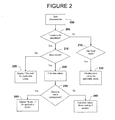
- FIG. 2 is a flow diagram illustrating a technique for representing the value of a limit in various forms including showing the value in terms of clock values or cycles of the system, according to some embodiments discussed herein.
- FIG. 3 shows an exemplary application of the method illustrated in FIG. 2 , wherein the method is applied specifically to DDR technology.
- FIG. 4 is a flowchart illustrating a method for determining the slew rate de-rated values, according to some embodiments herein.
- FIG. 5 shows screen displays of various exemplary reports, according to some embodiments of the invention.
- the embodiments herein provide methods and systems to measure and represent the measured value of a limit in terms of clock values or cycles of the system. Also, the methods and systems taught herein enable a designer to automatically determine the slew rate de-rated values. Further, the embodiments may be easily implemented in various other technologies such as Peripheral Component Interconnect Express (PCIe), Universal Serial Bus (USB), etc. A method of the invention may also be implemented as computer software, hardware, firmware, or any combination thereof.
- PCIe Peripheral Component Interconnect Express
- USB Universal Serial Bus
- references in the specification to "one embodiment” or “an embodiment” means that a particular feature, structure, characteristic, or function described in connection with the embodiment is included in at least one embodiment of the invention.
- the appearances of the phrase “in one embodiment” in various places in the specification are not necessarily all referring to the same embodiment.
- FIG. 1 shows a simplified block diagram of a system 100 to enable a user to view various limit calculations in terms of another measurement according to an embodiment of the present invention.
- the measurements of limits may be done in terms of clock values or cycles.
- the system 100 may be comprised of at least one client application 101 interacting with a layer called the master application layer 102.
- the master layer 102 may be a testing tool that enables a user to perform eye diagram and jitter analysis at the display port.
- the client application 101 includes logic to communicate the information such as clock rate, etc., to the master application layer 102.
- the master application layer 102 also provides the necessary infrastructure for a client application 101 to plug-in the implementation for dynamic limits and units.
- a relative limit calculation module 103 further interacts with the master application layer 102 to obtain information on input/output parameters dynamically. These are further processed and represented to the user in terms of another measurement such as the clock rate or other value related to the clock.
- the method can include various steps such as the following. First, when a particular measurement that needs a dynamic limit is selected, the master application 102 can automatically add the contributing measurements. So, the client application 101 that uses this feature has the knowledge of all the contributing measurements to be added into master application 102.
- information about the dynamic limits can be displayed to the user on a display device.
- the master application layer 102 results panel can display, for example, a 'Derived...' indicator in the limits field.
- the user can have access to more information such as 'This limit is calculated based on Measure X' by hovering the mouse pointer over the 'Derived...' indicator.
- the limit field can display, for example, an 'Error...' indicator, and by hovering the mouse over the 'Error...' indicator, additional information can be displayed to the user on the display device such as 'This limit is calculated based on Measure X.'
- FIG. 2 is a flow diagram illustrating a technique for representing the value of a limit in various forms including showing the value in terms of clock values or cycles of the system, according to some embodiments discussed herein.
- the system can also include logic to obtain information from the one or more client applications 101 attached to the master application layer 102. If the client application 101 attached does not enable measurements of dynamic limits relative to the measured value, the static values of applicable limits can instead be displayed on the display device.
- a measurement is added.
- the flow then proceeds to 205 where a determination is made whether limits are to be calculated. If No, the flow proceeds to 215 and 230 where static values for applicable limits are displayed when the limits are fixed. Otherwise, the flow proceeds to 210 and a determination is made whether the results are available. If No, meaning the results are not available, the flow proceeds to 220 and 'Derived...' is displayed for applicable limits. Otherwise, if Yes, the flow proceeds to 225 and the values are calculated.
- a determination is made whether there are errors in the limits calculations. If Yes, the flow proceeds to 240 and 'Error...' for applicable limits is displayed. Otherwise, if no errors, the flow proceeds to 245 and further values are calculated, and if needed, one or more tool tips can be displayed.
- the method of FIG. 2 is applied specifically to DDR technology.
- the oscilloscope system 303 communicates with the oscilloscope hardware 304 to get the acquired data from a device-under-test (DUT) 306.
- the master application 102 which can include jitter and eye analysis tools such as DPOJET, will analyze the acquired data and produce base measurements.
- the compliance layer 101 which can include DDR analysis capability such as DDRA for DDR technologies, will use the DPOJET base measurements 102 to produce further measurements. Dynamic limits and units reside in the compliance layer 101.
- FIG. 4 is a flowchart illustrating the method for determining the slew rate de-rated values, according to some embodiments herein.
- the DDRA is a compliance solution for DDR technology that works with the base measurements of the master application layer.
- the master application layer is basically a tool for eye-diagram and jitter test analysis. It supports rise, fall slew rate, setup and hold measurements, and their related configurations, which are used to compute slew rate de-rating.
- the base measurements of the master application layer are imported at 401.
- the slew rate technique is configurable in the master application layer.
- the user selects DDR technique to compute the slew rate.
- automatic switching between the nominal and tangent approach is performed depending on the maximum slope, in accordance with JEDEC DDR2 and DDR3 specifications.
- step 404 correct reference levels for each of these measurements are set. These reference levels are different for single-ended and differential signals.
- slew rate for rise and fall are computed separately on each slope and cycle, and the mean value is determined. The mean value of 'n' cycles is used for further processing. The 'n' here represents the number of cycles set by the master application layer. Since both rise and fall slopes are obtained for each cycle, the single slew rate is calculated as average of rise and fall mean values.
- a delta value is obtained by using slew rate values to index the specific de-rating tables.
- the de-rating limit value is calculated by using the delta value.
- the system may be integrated in an arbitrary waveform generator.
- the master application layer stores the de-rating table in the oscilloscope installed location.
- a user can edit the 'x' and 'y' values.
- 'x' can correspond to slew rate of data strobe (e.g., DQS) and 'y' can correspond to slew rate of data (e.g., DQ).
- DQS data e.g., DQS
- DQ slew rate of data
- the application is not tied up with the fixed table.
- the user can edit the de-rating tables when he/she wants to debug with any other datasheet values or even a change in the specification.
- the user can run multiple measurements with a 'single' button selection in the application, which enables it to perform the complicated and time consuming de-rated measurements accurately.
- FIG. 5 Various exemplary reports are shown in FIG. 5 , which can be displayed using a display device of the system.
- the first measurement is a base measurement which has, for example, 200ps as the limit as shown at 505.
- the second measurement for example, is address and control input total setup time (tIS) de-rated as shown at 510, which has de-rated the limit value.
- tIS total setup time
- highlighted portion shows 'Derived...' at 515 for the limits that are dynamic.
- embodiments of the invention as described above provide a means for automatically obtaining results as scalar de-rating values. Further, the user is not restricted to use the fixed values of the de-rating tables and can change the values based on the particular design's needs.
- the user is provided with a fully automated suite of measurements having appropriate limits that are calculated on the dynamically based (i.e., pre requisite) measurements.
- Tool tip displays the required information (e.g., such as dependent parameters) to the user before selecting an action button or indicator such as 'Run' or 'Single.'
Landscapes
- Engineering & Computer Science (AREA)
- General Engineering & Computer Science (AREA)
- Physics & Mathematics (AREA)
- General Physics & Mathematics (AREA)
- Theoretical Computer Science (AREA)
- Computer Hardware Design (AREA)
- Quality & Reliability (AREA)
- Debugging And Monitoring (AREA)
- Measurement Of Current Or Voltage (AREA)
- Tests Of Electronic Circuits (AREA)
Abstract
Description
- The present invention relates generally to oscilloscopes, and more particularly, to user interfaces, methods, and systems for measuring and representing values in signal measurement systems.
- Double data rate (DDR) memory technology has become more prevalent in the marketplace, and includes the capability of clocking data on both rising and falling edges of a strobe signal in a memory interface. Similarly, the next generation DDR2 technology has provided an additional two-times improvement in bandwidth over its DDR predecessor by doubling the maximum clock frequency.
- With any high-speed interface, as the operating frequencies increase, it becomes progressively more difficult to meet the signal integrity and timing requirements at the receivers. With tighter timing budgets, signals tend to deteriorate because faster edge rates are needed to meet them. As edge rates get faster, effects like overshoot, reflections, and crosstalk become more significant problems on the interface resulting in a negative impact on the timing budget. A significant change incorporated into next generations of DDR technology to counter the impact on the timing budget is signal slew rate de-rating for both data and address/command signals.
- One challenging aspect of the memory interface designers is to meet the setup and hold time requirements of the receivers. The setup and hold time values vary depending on the input signal slew rate. In order to compute slew rate properly, a user needs to know how to measure signal slew rate, and how to make use of Joint Electron Device Engineering Council (JEDEC) specified de-rating tables.
- In DDR2 technology, the typical definition for the setup and hold time for memory components is 1.0Volt/nano-second (V/ns) input slew rate. By design, slew rate of a memory chip can be faster or slower. Accordingly, the setup and hold time requirements are changed, since the user cannot use the same slew rate of 1.0V/ns. This discrepancy has led to the need for slew rate de-rating on the signals specific to user design.
- Conventional attempts at solving these challenges implement a series of manual steps, including manual measurements, which are cumbersome and challenging to complete.
- The following steps are an example of a typical approach. First, the slew rate on the input signal is measured. This is done by finding nominal slew rate of the signal in the transition region between the specified voltage levels. The nominal method and voltage levels are defined in the JEDEC DDR2 and DDR3 specifications. Second, a determination is made whether the region of interest of the signal needs to use the nominal or the tangent method. The tangent method is used if signal transition results in a slope greater than the nominal line at the switching region. Tangent method is also defined in the JEDEC DDR2 and DDR3 specifications. It is time consuming to detect the slopes and then decide on which method to use as the slope has to be calculated for each sample point from the reference level between the two voltage levels. According to the specification, it has to be ensured that the slope occurring due to tangent should be earlier than the nominal line.
- Next, slew rate on both rise and fall slopes for all the acquired transitions is computed. The cycle-by-cycle slew should be calculated to know the worst case behavior of the device under test (DUT), which is tedious to perform on rise and fall slopes, particularly when the acquired signal duration is long enough to accommodate hundreds of cycles. Meanwhile, the correct relationship between the polarity of the de-rating value and the direction of margin impact must be maintained. Thereafter, the slew rate on two separate signals is computed. A user makes use of the two typical slew rate values to index the appropriate de-rating table. The JEDEC specifies different tables for the different speeds to obtain the delta value. Finally, the delta value is added to the limits taken from the data sheet of the base measurement, which represents the de-rated limits.
- Thus, the designers of high speed communication technologies need to perform various and laborious calculations of the limits to understand the dynamic behavior of the system. Moreover, with the emergence of DDR memory technologies, the measurements which were static needed to be calculated over and over again by a designer to get a deeper understanding of the behavior of the system in hand. Further, such manual measurements are error prone.
- Therefore, a need remains for an improved solution where a designer can easily carry out various calculations of the limits to understand the dynamic behavior of the system.
- Embodiments of the invention enable a designer to derive limits using another measured value, thereby providing dynamic and relative measurements so that the designer can more effectively design systems.
- Some embodiments of the invention provide for the calculation of limits in terms of actual clock values or cycles, and also display the units as normalized clock values or cycles, as explained in further detail below.
- Some embodiments enable a designer to automatically determine the slew rate de-rated values through the configurable lookup tables, as further discussed herein.
- In accordance with various embodiments of the invention, a method and a system are provided for measuring and representing the measured value of a limit in terms of another measurement, and also for automatically determining slew rate de-rating values on the signals specific to user design by providing automatic and configurable de-rating tables.
- In some embodiments, a master application layer may be developed for providing necessary infrastructure for a client application to plug-in the implementation for dynamic limits and units. Said master application layer sends required details to the client application. The client application makes limit calculations, and the values obtained after the limit calculations may be processed and represented in terms of another measurement. Thereafter, the said values may be sent back to the master application layer for display.
- In some embodiments, slew rate de-rating values on the signals specific to user design may be determined by providing automatic and configurable de-rating tables, and the master application layer that supports measurements including but not limited to rise, fall slew rate, setup and hold and their related configurations, may be used for computing slew rate de-rating. This may be accomplished by the master application layer, which can automatically switch between nominal approach and tangent approach depending on the maximum slope when a user selects DDR method for determining the slew rate.
- In various embodiments herein, the calculated de-rating limit value may be given as tDS (total setup time) = tDS(base) + ΔtDS, where the data sheet limit value of tDS(base) may be added to (i.e., summed with) the ΔtDS de-rating value taken from the de-rating table.
- In one embodiment herein, the master application layer may be a testing application layer that may store the de-rating table, which can be edited any time by a user. Also, the user can run multiple measurements with a 'single' button selection presented as part of the user interface of the application, which causes the system to perform the complicated and time consuming de-rated measurements accurately.
- Other features and advantages of the invention will be apparent from the drawings, and from the detailed description that follows below.
- Reference will be made to embodiments of the invention, examples of which may be illustrated in the accompanying figures. These figures are intended to be illustrative, and are not limiting. Although the invention is generally described in the context of these embodiments, it should be understood that by doing so, it is not intended to limit the scope of the invention to these particular embodiments.
-
FIG. 1 illustrates a system to measure and represent the measured value of a limit in terms of clock values or cycles of the system, according to an embodiment of the present invention. -
FIG. 2 is a flow diagram illustrating a technique for representing the value of a limit in various forms including showing the value in terms of clock values or cycles of the system, according to some embodiments discussed herein. -
FIG. 3 shows an exemplary application of the method illustrated inFIG. 2 , wherein the method is applied specifically to DDR technology. -
FIG. 4 is a flowchart illustrating a method for determining the slew rate de-rated values, according to some embodiments herein. -
FIG. 5 shows screen displays of various exemplary reports, according to some embodiments of the invention. - The embodiments herein provide methods and systems to measure and represent the measured value of a limit in terms of clock values or cycles of the system. Also, the methods and systems taught herein enable a designer to automatically determine the slew rate de-rated values. Further, the embodiments may be easily implemented in various other technologies such as Peripheral Component Interconnect Express (PCIe), Universal Serial Bus (USB), etc. A method of the invention may also be implemented as computer software, hardware, firmware, or any combination thereof.
- The invention described herein is explained using specific exemplary details to facilitate an understanding. However, the invention disclosed can be implemented by a person that is skilled in the art without the use of these specific details. The invention can be implemented into various types of digital storage oscilloscopes. Further, the invention may be implemented in hardware as well as software. Structures and devices shown in block diagrams are illustrative of exemplary embodiments of the invention. Also, the connections between various elements may not necessarily be direct and the data transfer in-between can be subjected to encoding, re-formatting, modifications, and so forth.
- References in the specification to "one embodiment" or "an embodiment" means that a particular feature, structure, characteristic, or function described in connection with the embodiment is included in at least one embodiment of the invention. The appearances of the phrase "in one embodiment" in various places in the specification are not necessarily all referring to the same embodiment.
-
FIG. 1 shows a simplified block diagram of asystem 100 to enable a user to view various limit calculations in terms of another measurement according to an embodiment of the present invention. For example, the measurements of limits may be done in terms of clock values or cycles. - In one embodiment, the
system 100 may be comprised of at least oneclient application 101 interacting with a layer called themaster application layer 102. In one embodiment of the invention, themaster layer 102 may be a testing tool that enables a user to perform eye diagram and jitter analysis at the display port. Theclient application 101 includes logic to communicate the information such as clock rate, etc., to themaster application layer 102. Themaster application layer 102 also provides the necessary infrastructure for aclient application 101 to plug-in the implementation for dynamic limits and units. - A relative
limit calculation module 103 further interacts with themaster application layer 102 to obtain information on input/output parameters dynamically. These are further processed and represented to the user in terms of another measurement such as the clock rate or other value related to the clock. - The method can include various steps such as the following. First, when a particular measurement that needs a dynamic limit is selected, the
master application 102 can automatically add the contributing measurements. So, theclient application 101 that uses this feature has the knowledge of all the contributing measurements to be added intomaster application 102. - In a further step, information about the dynamic limits can be displayed to the user on a display device. After the measurement is added, the
master application layer 102 results panel can display, for example, a 'Derived...' indicator in the limits field. In addition, the user can have access to more information such as 'This limit is calculated based on Measure X' by hovering the mouse pointer over the 'Derived...' indicator. If there is an error in calculating dynamic limits, the limit field can display, for example, an 'Error...' indicator, and by hovering the mouse over the 'Error...' indicator, additional information can be displayed to the user on the display device such as 'This limit is calculated based on Measure X.' -
FIG. 2 is a flow diagram illustrating a technique for representing the value of a limit in various forms including showing the value in terms of clock values or cycles of the system, according to some embodiments discussed herein. The system can also include logic to obtain information from the one ormore client applications 101 attached to themaster application layer 102. If theclient application 101 attached does not enable measurements of dynamic limits relative to the measured value, the static values of applicable limits can instead be displayed on the display device. - More specifically, at 200, a measurement is added. The flow then proceeds to 205 where a determination is made whether limits are to be calculated. If No, the flow proceeds to 215 and 230 where static values for applicable limits are displayed when the limits are fixed. Otherwise, the flow proceeds to 210 and a determination is made whether the results are available. If No, meaning the results are not available, the flow proceeds to 220 and 'Derived...' is displayed for applicable limits. Otherwise, if Yes, the flow proceeds to 225 and the values are calculated. At 235, a determination is made whether there are errors in the limits calculations. If Yes, the flow proceeds to 240 and 'Error...' for applicable limits is displayed. Otherwise, if no errors, the flow proceeds to 245 and further values are calculated, and if needed, one or more tool tips can be displayed.
- In an exemplary embodiment as shown in
FIG. 3 , the method ofFIG. 2 is applied specifically to DDR technology. In this embodiment, theoscilloscope system 303 communicates with theoscilloscope hardware 304 to get the acquired data from a device-under-test (DUT) 306. Themaster application 102, which can include jitter and eye analysis tools such as DPOJET, will analyze the acquired data and produce base measurements. Thecompliance layer 101, which can include DDR analysis capability such as DDRA for DDR technologies, will use theDPOJET base measurements 102 to produce further measurements. Dynamic limits and units reside in thecompliance layer 101. -
FIG. 4 is a flowchart illustrating the method for determining the slew rate de-rated values, according to some embodiments herein. - As explained above, automatic and configurable de-rating tables are provided that help in calculating accurate results. The DDRA is a compliance solution for DDR technology that works with the base measurements of the master application layer. The master application layer is basically a tool for eye-diagram and jitter test analysis. It supports rise, fall slew rate, setup and hold measurements, and their related configurations, which are used to compute slew rate de-rating.
- The base measurements of the master application layer are imported at 401. The slew rate technique is configurable in the master application layer. At 402, the user selects DDR technique to compute the slew rate. At 403, automatic switching between the nominal and tangent approach is performed depending on the maximum slope, in accordance with JEDEC DDR2 and DDR3 specifications.
- Thereafter, in
step 404, correct reference levels for each of these measurements are set. These reference levels are different for single-ended and differential signals. At 405, slew rate for rise and fall are computed separately on each slope and cycle, and the mean value is determined. The mean value of 'n' cycles is used for further processing. The 'n' here represents the number of cycles set by the master application layer. Since both rise and fall slopes are obtained for each cycle, the single slew rate is calculated as average of rise and fall mean values. At 406, a delta value is obtained by using slew rate values to index the specific de-rating tables. Finally, at 407, the de-rating limit value is calculated by using the delta value. - The calculated de-rating limit value may appear as:

- where the data sheet limit value of tDS(base) is added with the ΔtDS de-rating value taken from the de-rating table as explained above.
- In an exemplary embodiment of the present invention, the system may be integrated in an arbitrary waveform generator. The master application layer stores the de-rating table in the oscilloscope installed location. A user can edit the 'x' and 'y' values. For example, 'x' can correspond to slew rate of data strobe (e.g., DQS) and 'y' can correspond to slew rate of data (e.g., DQ). In this way, the application is not tied up with the fixed table. The user can edit the de-rating tables when he/she wants to debug with any other datasheet values or even a change in the specification. Also, the user can run multiple measurements with a 'single' button selection in the application, which enables it to perform the complicated and time consuming de-rated measurements accurately.
- Various exemplary reports are shown in
FIG. 5 , which can be displayed using a display device of the system. - In
FIG. 5(a) , the first measurement is a base measurement which has, for example, 200ps as the limit as shown at 505. The second measurement, for example, is address and control input total setup time (tIS) de-rated as shown at 510, which has de-rated the limit value. - In
FIG. 5(b) , highlighted portion shows 'Derived...' at 515 for the limits that are dynamic. - In
FIG. 5(c) , the highlighted portion at 520 shows the calculated limits, and mouse hover message is shown at 525. - Thus, embodiments of the invention as described above provide a means for automatically obtaining results as scalar de-rating values. Further, the user is not restricted to use the fixed values of the de-rating tables and can change the values based on the particular design's needs.
- Moreover, the user is provided with a fully automated suite of measurements having appropriate limits that are calculated on the dynamically based (i.e., pre requisite) measurements.
- For situations in which the dependency for a measurement is not another measurement, but rather, input voltage levels (e.g., such as Vdd values), these may be flexibly handled by master-client interfaces. Further, all the measurements and/or parameters that contribute to the dynamic limits may automatically be selected according to the JEDEC standard. The user need not have any prerequisite knowledge.
- Furthermore, the user can be made aware which of the limits are dynamically applied, and also the dependent parameters, by looking at the results. This helps the user in getting appropriate information at a glance without running the measurement. Tool tip displays the required information (e.g., such as dependent parameters) to the user before selecting an action button or indicator such as 'Run' or 'Single.'
- Although particular embodiments have been described, it will be appreciated that the principles of the invention are not limited to those embodiments. For example, in addition to the oscilloscope hardware described above, the embodiments disclosed herein can be embodied or associated with any type of test and measurement apparatus, and need not be limited to a single system, but can be associated with one or more test and measurement devices. Variations and modifications may be made without departing from the principles of the invention as set forth in the following claims.
Claims (11)
- A method for automatically determining slew rate de-rating values on the signals specific to user design by providing automatic and configurable de-rating tables, comprising providing a master application layer that supports measurements including rise, fall, slew rate, setup and hold, and configurations for computing slew rate de-rating.
- The method as in claim 1, wherein the master application layer automatically switches between nominal approach and tangent approach depending on the maximum slope when a user selects DDR method for determining the slew rate.
- The method as in claim 1, wherein the master application layer sets up the correct reference levels for each measurement.
- The method as in claim 1, wherein the slew rate is automatically computed for rise and fall separately on each slope and cycle, and mean value of 'n' number of cycles is used for further processing.
- The method as in claim 4, wherein the master application layer sets the number of cycles 'n'.
- The method as in claim 1, wherein the slew rate is determined for a plurality of sources pair signals, and the slew rate values for each pair are used to index the specific de-rating tables to get the delta value.
- The method as in claim 1, wherein the calculated de-rating limit value is given as:

where the data sheet limit value of tDS(base) is added with the ΔtDS de-rating value taken from the de-rating tables. - The method as in claim 1, wherein the master application layer stores the de-rating tables, which are editable at any time by a user.
- The method as in claim 1, wherein a user can run multiple measurements with a 'single' button selection in the application, thereby efficiently obtaining accurate de-rated measurements.
- The method as in claim 1, further comprising acquiring information from a device under test using a test and measurement instrument, wherein the information is processed by the master application layer.
- An article drawn from the set including floppy disks, optical disks, fixed disks, random access memory, read-only memory, or flash memory, comprising a machine-accessible medium having associated instructions that, when executed in a test and measurement device, results in a machine performing the steps of any preceding claim.
Applications Claiming Priority (2)
| Application Number | Priority Date | Filing Date | Title |
|---|---|---|---|
| IN1254MU2009 | 2009-05-15 | ||
| IN1255MU2009 | 2009-05-15 |
Publications (3)
| Publication Number | Publication Date |
|---|---|
| EP2256509A2 true EP2256509A2 (en) | 2010-12-01 |
| EP2256509A3 EP2256509A3 (en) | 2010-12-15 |
| EP2256509B1 EP2256509B1 (en) | 2014-07-09 |
Family
ID=42272726
Family Applications (2)
| Application Number | Title | Priority Date | Filing Date |
|---|---|---|---|
| EP10250930.4A Not-in-force EP2256509B1 (en) | 2009-05-15 | 2010-05-14 | Method and system to measure and represent the measured value of a limit in terms of another measurement in a signal measurement system |
| EP10250927.0A Not-in-force EP2253965B1 (en) | 2009-05-15 | 2010-05-14 | Method and system to measure and represent the measured value of a limit in terms of another measurement in a signal measurement system |
Family Applications After (1)
| Application Number | Title | Priority Date | Filing Date |
|---|---|---|---|
| EP10250927.0A Not-in-force EP2253965B1 (en) | 2009-05-15 | 2010-05-14 | Method and system to measure and represent the measured value of a limit in terms of another measurement in a signal measurement system |
Country Status (5)
| Country | Link |
|---|---|
| US (1) | US8670947B2 (en) |
| EP (2) | EP2256509B1 (en) |
| JP (1) | JP5481272B2 (en) |
| KR (1) | KR101652779B1 (en) |
| CN (1) | CN101923107B (en) |
Families Citing this family (2)
| Publication number | Priority date | Publication date | Assignee | Title |
|---|---|---|---|---|
| US11293982B2 (en) | 2019-03-07 | 2022-04-05 | Rohde & Schwarz Gmbh & Co. Kg | Test method and test system |
| US20240362385A1 (en) * | 2023-04-28 | 2024-10-31 | Synopsys, Inc. | Adjustments to superconducting electronic circuit designs using passive transmission line modeling |
Family Cites Families (6)
| Publication number | Priority date | Publication date | Assignee | Title |
|---|---|---|---|---|
| US6263290B1 (en) * | 1995-02-22 | 2001-07-17 | Michael K. Williams | Process and machine for signal waveform analysis |
| US6195617B1 (en) * | 1998-03-09 | 2001-02-27 | Lecroy, S.A. | Digital storage oscilloscope with simultaneous primary measurement and derived parameter display on common time axis and method therefor |
| US6836738B2 (en) * | 2002-03-14 | 2004-12-28 | Tektronix, Inc. | Method for optimized rendering of eye diagrams synchronized to a recovered clock and based on a single shot acquisition |
| US7522661B2 (en) * | 2004-07-26 | 2009-04-21 | Tektronix, Inc. | Method of producing a two-dimensional probability density function (PDF) eye diagram and Bit Error Rate eye arrays |
| US7428717B1 (en) | 2006-01-30 | 2008-09-23 | Xilinx, Inc. | Integrated system noise management—system level |
| US8816738B2 (en) * | 2008-03-18 | 2014-08-26 | Micron Technology, Inc. | Controlling slew rate performance across different output driver impedances |
-
2010
- 2010-04-30 US US12/771,977 patent/US8670947B2/en not_active Expired - Fee Related
- 2010-05-13 JP JP2010111387A patent/JP5481272B2/en not_active Expired - Fee Related
- 2010-05-14 KR KR1020100045445A patent/KR101652779B1/en not_active Expired - Fee Related
- 2010-05-14 EP EP10250930.4A patent/EP2256509B1/en not_active Not-in-force
- 2010-05-14 CN CN201010233568.XA patent/CN101923107B/en not_active Expired - Fee Related
- 2010-05-14 EP EP10250927.0A patent/EP2253965B1/en not_active Not-in-force
Non-Patent Citations (1)
| Title |
|---|
| None |
Also Published As
| Publication number | Publication date |
|---|---|
| US20110119688A1 (en) | 2011-05-19 |
| US8670947B2 (en) | 2014-03-11 |
| EP2253965B1 (en) | 2015-07-08 |
| KR101652779B1 (en) | 2016-08-31 |
| KR20100123653A (en) | 2010-11-24 |
| CN101923107A (en) | 2010-12-22 |
| JP2010266444A (en) | 2010-11-25 |
| EP2256509B1 (en) | 2014-07-09 |
| JP5481272B2 (en) | 2014-04-23 |
| EP2256509A3 (en) | 2010-12-15 |
| EP2253965A2 (en) | 2010-11-24 |
| CN101923107B (en) | 2016-05-11 |
| EP2253965A3 (en) | 2010-12-15 |
Similar Documents
| Publication | Publication Date | Title |
|---|---|---|
| US20140046647A1 (en) | Active trace assertion based verification system | |
| JP6738798B2 (en) | One shot circuit and automatic test equipment | |
| TWI729553B (en) | Image testing system and its testing assembly | |
| US20170185709A1 (en) | Method and apparatus for adjusting a timing derate for static timing analysis | |
| US12276695B2 (en) | Chip testing method and apparatus | |
| US20050262396A1 (en) | Apparatus and method for automated test setup | |
| CN111190089B (en) | Method and device for determining jitter time, storage medium and electronic equipment | |
| CN101325410A (en) | Delay circuit and delay method | |
| EP2256509B1 (en) | Method and system to measure and represent the measured value of a limit in terms of another measurement in a signal measurement system | |
| JP5785725B2 (en) | Power estimation apparatus, power estimation method and program | |
| TWI521220B (en) | Timing analysis method for integrated circuit and computer program product thereof | |
| EP1870725B1 (en) | Test device, test method, electronic device manufacturing method, test simulator, and test simulation method | |
| JP5577035B2 (en) | Locally ordered strobing | |
| US7363568B2 (en) | System and method for testing differential signal crossover using undersampling | |
| CN104038380A (en) | Server motherboard detection system and method | |
| US7634371B2 (en) | System and method for analyzing jitter of signals | |
| CN113495225A (en) | Power supply stability test method, system and equipment | |
| US6879178B1 (en) | Measuring current on a die | |
| TWI437454B (en) | Method and estimating apparatus for estimating of a noise fluctuation of a semiconductor device | |
| CN110888045B (en) | Jitter determination method and device, storage medium and electronic device | |
| JP2012053651A (en) | Timing analysis method, program and system | |
| US20070113136A1 (en) | Detection rate calculation method of test pattern, recording medium, and detection rate calculation apparatus of test pattern | |
| US20190324060A1 (en) | Oscilloscope system | |
| US6647538B1 (en) | Apparatus and method for signal skew characterization utilizing clock division | |
| JP5233786B2 (en) | Estimate support program, estimate support apparatus, and estimate support method |
Legal Events
| Date | Code | Title | Description |
|---|---|---|---|
| PUAI | Public reference made under article 153(3) epc to a published international application that has entered the european phase |
Free format text: ORIGINAL CODE: 0009012 |
|
| PUAL | Search report despatched |
Free format text: ORIGINAL CODE: 0009013 |
|
| AK | Designated contracting states |
Kind code of ref document: A2 Designated state(s): AL AT BE BG CH CY CZ DE DK EE ES FI FR GB GR HR HU IE IS IT LI LT LU LV MC MK MT NL NO PL PT RO SE SI SK SM TR |
|
| AX | Request for extension of the european patent |
Extension state: BA ME RS |
|
| AK | Designated contracting states |
Kind code of ref document: A3 Designated state(s): AL AT BE BG CH CY CZ DE DK EE ES FI FR GB GR HR HU IE IS IT LI LT LU LV MC MK MT NL NO PL PT RO SE SI SK SM TR |
|
| AX | Request for extension of the european patent |
Extension state: BA ME RS |
|
| RIC1 | Information provided on ipc code assigned before grant |
Ipc: G01R 31/317 20060101AFI20101018BHEP Ipc: G11C 29/50 20060101ALI20101105BHEP |
|
| 17P | Request for examination filed |
Effective date: 20110615 |
|
| 17Q | First examination report despatched |
Effective date: 20111116 |
|
| REG | Reference to a national code |
Ref country code: DE Ref legal event code: R079 Ref document number: 602010017331 Country of ref document: DE Free format text: PREVIOUS MAIN CLASS: G01R0031317000 Ipc: G01R0013020000 |
|
| RIC1 | Information provided on ipc code assigned before grant |
Ipc: G01R 13/02 20060101AFI20131113BHEP Ipc: G01R 31/317 20060101ALI20131113BHEP |
|
| GRAP | Despatch of communication of intention to grant a patent |
Free format text: ORIGINAL CODE: EPIDOSNIGR1 |
|
| INTG | Intention to grant announced |
Effective date: 20140107 |
|
| GRAS | Grant fee paid |
Free format text: ORIGINAL CODE: EPIDOSNIGR3 |
|
| GRAA | (expected) grant |
Free format text: ORIGINAL CODE: 0009210 |
|
| AK | Designated contracting states |
Kind code of ref document: B1 Designated state(s): AL AT BE BG CH CY CZ DE DK EE ES FI FR GB GR HR HU IE IS IT LI LT LU LV MC MK MT NL NO PL PT RO SE SI SK SM TR |
|
| REG | Reference to a national code |
Ref country code: GB Ref legal event code: FG4D |
|
| REG | Reference to a national code |
Ref country code: CH Ref legal event code: EP Ref country code: AT Ref legal event code: REF Ref document number: 676761 Country of ref document: AT Kind code of ref document: T Effective date: 20140715 |
|
| REG | Reference to a national code |
Ref country code: IE Ref legal event code: FG4D |
|
| REG | Reference to a national code |
Ref country code: DE Ref legal event code: R096 Ref document number: 602010017331 Country of ref document: DE Effective date: 20140821 |
|
| REG | Reference to a national code |
Ref country code: AT Ref legal event code: MK05 Ref document number: 676761 Country of ref document: AT Kind code of ref document: T Effective date: 20140709 |
|
| REG | Reference to a national code |
Ref country code: NL Ref legal event code: VDEP Effective date: 20140709 |
|
| REG | Reference to a national code |
Ref country code: LT Ref legal event code: MG4D |
|
| PG25 | Lapsed in a contracting state [announced via postgrant information from national office to epo] |
Ref country code: FI Free format text: LAPSE BECAUSE OF FAILURE TO SUBMIT A TRANSLATION OF THE DESCRIPTION OR TO PAY THE FEE WITHIN THE PRESCRIBED TIME-LIMIT Effective date: 20140709 Ref country code: SE Free format text: LAPSE BECAUSE OF FAILURE TO SUBMIT A TRANSLATION OF THE DESCRIPTION OR TO PAY THE FEE WITHIN THE PRESCRIBED TIME-LIMIT Effective date: 20140709 Ref country code: PT Free format text: LAPSE BECAUSE OF FAILURE TO SUBMIT A TRANSLATION OF THE DESCRIPTION OR TO PAY THE FEE WITHIN THE PRESCRIBED TIME-LIMIT Effective date: 20141110 Ref country code: ES Free format text: LAPSE BECAUSE OF FAILURE TO SUBMIT A TRANSLATION OF THE DESCRIPTION OR TO PAY THE FEE WITHIN THE PRESCRIBED TIME-LIMIT Effective date: 20140709 Ref country code: NO Free format text: LAPSE BECAUSE OF FAILURE TO SUBMIT A TRANSLATION OF THE DESCRIPTION OR TO PAY THE FEE WITHIN THE PRESCRIBED TIME-LIMIT Effective date: 20141009 Ref country code: GR Free format text: LAPSE BECAUSE OF FAILURE TO SUBMIT A TRANSLATION OF THE DESCRIPTION OR TO PAY THE FEE WITHIN THE PRESCRIBED TIME-LIMIT Effective date: 20141010 Ref country code: LT Free format text: LAPSE BECAUSE OF FAILURE TO SUBMIT A TRANSLATION OF THE DESCRIPTION OR TO PAY THE FEE WITHIN THE PRESCRIBED TIME-LIMIT Effective date: 20140709 Ref country code: BG Free format text: LAPSE BECAUSE OF FAILURE TO SUBMIT A TRANSLATION OF THE DESCRIPTION OR TO PAY THE FEE WITHIN THE PRESCRIBED TIME-LIMIT Effective date: 20141009 |
|
| PG25 | Lapsed in a contracting state [announced via postgrant information from national office to epo] |
Ref country code: CY Free format text: LAPSE BECAUSE OF FAILURE TO SUBMIT A TRANSLATION OF THE DESCRIPTION OR TO PAY THE FEE WITHIN THE PRESCRIBED TIME-LIMIT Effective date: 20140709 Ref country code: AT Free format text: LAPSE BECAUSE OF FAILURE TO SUBMIT A TRANSLATION OF THE DESCRIPTION OR TO PAY THE FEE WITHIN THE PRESCRIBED TIME-LIMIT Effective date: 20140709 Ref country code: HR Free format text: LAPSE BECAUSE OF FAILURE TO SUBMIT A TRANSLATION OF THE DESCRIPTION OR TO PAY THE FEE WITHIN THE PRESCRIBED TIME-LIMIT Effective date: 20140709 Ref country code: LV Free format text: LAPSE BECAUSE OF FAILURE TO SUBMIT A TRANSLATION OF THE DESCRIPTION OR TO PAY THE FEE WITHIN THE PRESCRIBED TIME-LIMIT Effective date: 20140709 Ref country code: IS Free format text: LAPSE BECAUSE OF FAILURE TO SUBMIT A TRANSLATION OF THE DESCRIPTION OR TO PAY THE FEE WITHIN THE PRESCRIBED TIME-LIMIT Effective date: 20141109 Ref country code: NL Free format text: LAPSE BECAUSE OF FAILURE TO SUBMIT A TRANSLATION OF THE DESCRIPTION OR TO PAY THE FEE WITHIN THE PRESCRIBED TIME-LIMIT Effective date: 20140709 Ref country code: PL Free format text: LAPSE BECAUSE OF FAILURE TO SUBMIT A TRANSLATION OF THE DESCRIPTION OR TO PAY THE FEE WITHIN THE PRESCRIBED TIME-LIMIT Effective date: 20140709 |
|
| REG | Reference to a national code |
Ref country code: DE Ref legal event code: R097 Ref document number: 602010017331 Country of ref document: DE |
|
| PG25 | Lapsed in a contracting state [announced via postgrant information from national office to epo] |
Ref country code: EE Free format text: LAPSE BECAUSE OF FAILURE TO SUBMIT A TRANSLATION OF THE DESCRIPTION OR TO PAY THE FEE WITHIN THE PRESCRIBED TIME-LIMIT Effective date: 20140709 Ref country code: SK Free format text: LAPSE BECAUSE OF FAILURE TO SUBMIT A TRANSLATION OF THE DESCRIPTION OR TO PAY THE FEE WITHIN THE PRESCRIBED TIME-LIMIT Effective date: 20140709 Ref country code: CZ Free format text: LAPSE BECAUSE OF FAILURE TO SUBMIT A TRANSLATION OF THE DESCRIPTION OR TO PAY THE FEE WITHIN THE PRESCRIBED TIME-LIMIT Effective date: 20140709 Ref country code: DK Free format text: LAPSE BECAUSE OF FAILURE TO SUBMIT A TRANSLATION OF THE DESCRIPTION OR TO PAY THE FEE WITHIN THE PRESCRIBED TIME-LIMIT Effective date: 20140709 Ref country code: RO Free format text: LAPSE BECAUSE OF FAILURE TO SUBMIT A TRANSLATION OF THE DESCRIPTION OR TO PAY THE FEE WITHIN THE PRESCRIBED TIME-LIMIT Effective date: 20140709 |
|
| PLBE | No opposition filed within time limit |
Free format text: ORIGINAL CODE: 0009261 |
|
| STAA | Information on the status of an ep patent application or granted ep patent |
Free format text: STATUS: NO OPPOSITION FILED WITHIN TIME LIMIT |
|
| 26N | No opposition filed |
Effective date: 20150410 |
|
| PG25 | Lapsed in a contracting state [announced via postgrant information from national office to epo] |
Ref country code: SI Free format text: LAPSE BECAUSE OF FAILURE TO SUBMIT A TRANSLATION OF THE DESCRIPTION OR TO PAY THE FEE WITHIN THE PRESCRIBED TIME-LIMIT Effective date: 20140709 |
|
| REG | Reference to a national code |
Ref country code: CH Ref legal event code: PL |
|
| PG25 | Lapsed in a contracting state [announced via postgrant information from national office to epo] |
Ref country code: MC Free format text: LAPSE BECAUSE OF FAILURE TO SUBMIT A TRANSLATION OF THE DESCRIPTION OR TO PAY THE FEE WITHIN THE PRESCRIBED TIME-LIMIT Effective date: 20140709 Ref country code: LU Free format text: LAPSE BECAUSE OF FAILURE TO SUBMIT A TRANSLATION OF THE DESCRIPTION OR TO PAY THE FEE WITHIN THE PRESCRIBED TIME-LIMIT Effective date: 20150514 Ref country code: CH Free format text: LAPSE BECAUSE OF NON-PAYMENT OF DUE FEES Effective date: 20150531 Ref country code: LI Free format text: LAPSE BECAUSE OF NON-PAYMENT OF DUE FEES Effective date: 20150531 |
|
| REG | Reference to a national code |
Ref country code: IE Ref legal event code: MM4A |
|
| PG25 | Lapsed in a contracting state [announced via postgrant information from national office to epo] |
Ref country code: IE Free format text: LAPSE BECAUSE OF NON-PAYMENT OF DUE FEES Effective date: 20150514 |
|
| REG | Reference to a national code |
Ref country code: FR Ref legal event code: PLFP Year of fee payment: 7 |
|
| PG25 | Lapsed in a contracting state [announced via postgrant information from national office to epo] |
Ref country code: BE Free format text: LAPSE BECAUSE OF FAILURE TO SUBMIT A TRANSLATION OF THE DESCRIPTION OR TO PAY THE FEE WITHIN THE PRESCRIBED TIME-LIMIT Effective date: 20140709 |
|
| PG25 | Lapsed in a contracting state [announced via postgrant information from national office to epo] |
Ref country code: MT Free format text: LAPSE BECAUSE OF FAILURE TO SUBMIT A TRANSLATION OF THE DESCRIPTION OR TO PAY THE FEE WITHIN THE PRESCRIBED TIME-LIMIT Effective date: 20140709 |
|
| REG | Reference to a national code |
Ref country code: FR Ref legal event code: PLFP Year of fee payment: 8 |
|
| PG25 | Lapsed in a contracting state [announced via postgrant information from national office to epo] |
Ref country code: HU Free format text: LAPSE BECAUSE OF FAILURE TO SUBMIT A TRANSLATION OF THE DESCRIPTION OR TO PAY THE FEE WITHIN THE PRESCRIBED TIME-LIMIT; INVALID AB INITIO Effective date: 20100514 Ref country code: SM Free format text: LAPSE BECAUSE OF FAILURE TO SUBMIT A TRANSLATION OF THE DESCRIPTION OR TO PAY THE FEE WITHIN THE PRESCRIBED TIME-LIMIT Effective date: 20140709 |
|
| PGFP | Annual fee paid to national office [announced via postgrant information from national office to epo] |
Ref country code: GB Payment date: 20170530 Year of fee payment: 8 Ref country code: FR Payment date: 20170525 Year of fee payment: 8 Ref country code: DE Payment date: 20170530 Year of fee payment: 8 |
|
| PG25 | Lapsed in a contracting state [announced via postgrant information from national office to epo] |
Ref country code: TR Free format text: LAPSE BECAUSE OF FAILURE TO SUBMIT A TRANSLATION OF THE DESCRIPTION OR TO PAY THE FEE WITHIN THE PRESCRIBED TIME-LIMIT Effective date: 20140709 |
|
| PGFP | Annual fee paid to national office [announced via postgrant information from national office to epo] |
Ref country code: IT Payment date: 20170524 Year of fee payment: 8 |
|
| PG25 | Lapsed in a contracting state [announced via postgrant information from national office to epo] |
Ref country code: MK Free format text: LAPSE BECAUSE OF FAILURE TO SUBMIT A TRANSLATION OF THE DESCRIPTION OR TO PAY THE FEE WITHIN THE PRESCRIBED TIME-LIMIT Effective date: 20140709 |
|
| PG25 | Lapsed in a contracting state [announced via postgrant information from national office to epo] |
Ref country code: AL Free format text: LAPSE BECAUSE OF FAILURE TO SUBMIT A TRANSLATION OF THE DESCRIPTION OR TO PAY THE FEE WITHIN THE PRESCRIBED TIME-LIMIT Effective date: 20140709 |
|
| REG | Reference to a national code |
Ref country code: DE Ref legal event code: R119 Ref document number: 602010017331 Country of ref document: DE |
|
| GBPC | Gb: european patent ceased through non-payment of renewal fee |
Effective date: 20180514 |
|
| PG25 | Lapsed in a contracting state [announced via postgrant information from national office to epo] |
Ref country code: DE Free format text: LAPSE BECAUSE OF NON-PAYMENT OF DUE FEES Effective date: 20181201 Ref country code: FR Free format text: LAPSE BECAUSE OF NON-PAYMENT OF DUE FEES Effective date: 20180531 Ref country code: GB Free format text: LAPSE BECAUSE OF NON-PAYMENT OF DUE FEES Effective date: 20180514 Ref country code: IT Free format text: LAPSE BECAUSE OF NON-PAYMENT OF DUE FEES Effective date: 20180514 |