EP2256489B1 - Method and apparatus for non-destructive testing using eddy currents. - Google Patents
Method and apparatus for non-destructive testing using eddy currents. Download PDFInfo
- Publication number
- EP2256489B1 EP2256489B1 EP10163776.7A EP10163776A EP2256489B1 EP 2256489 B1 EP2256489 B1 EP 2256489B1 EP 10163776 A EP10163776 A EP 10163776A EP 2256489 B1 EP2256489 B1 EP 2256489B1
- Authority
- EP
- European Patent Office
- Prior art keywords
- magnetic field
- magnetisable
- primary
- tertiary
- field
- Prior art date
- Legal status (The legal status is an assumption and is not a legal conclusion. Google has not performed a legal analysis and makes no representation as to the accuracy of the status listed.)
- Active
Links
Images

Classifications
-
- G—PHYSICS
- G01—MEASURING; TESTING
- G01N—INVESTIGATING OR ANALYSING MATERIALS BY DETERMINING THEIR CHEMICAL OR PHYSICAL PROPERTIES
- G01N27/00—Investigating or analysing materials by the use of electric, electrochemical, or magnetic means
- G01N27/72—Investigating or analysing materials by the use of electric, electrochemical, or magnetic means by investigating magnetic variables
- G01N27/82—Investigating or analysing materials by the use of electric, electrochemical, or magnetic means by investigating magnetic variables for investigating the presence of flaws
- G01N27/90—Investigating or analysing materials by the use of electric, electrochemical, or magnetic means by investigating magnetic variables for investigating the presence of flaws using eddy currents
- G01N27/9046—Investigating or analysing materials by the use of electric, electrochemical, or magnetic means by investigating magnetic variables for investigating the presence of flaws using eddy currents by analysing electrical signals
Definitions
- the invention relates to a method of non-clestructively testing a magnetisable conducting object mechanically shielded by a magnetisable layer, comprising the steps of abruptly changing a field strength of a primary magnetic field that is applied exterior to the magnetisable layer, receiving a vanishing secondary magnetic field generated by eddy currents induced by the changed field strength of the primary magnetic field, and analyzing a temporal field strength of the received secondary magnetic field for deriving characteristics of the magnetisable object.
- Magnetic fields are widely used for non-destructively testing magnetisable conducting objects, such as pipe lines or metal plates, e.g. for corrosion or cracks.
- the magnetisable object is probed by a primary magnetic field that is suddenly switched off, thereby inducing eddy currents in the object.
- the eddy currents generate a secondary magnetic field that may be measured to find characteristics of the tested object, such as local wall thickness.
- the method according to the invention further comprises the step of applying a transient tertiary magnetic field exterior to the magnetisable layer when the field strength of the primary magnetic field abruptly changes, wherein the orientation of the primary and tertiary magnetic field, respectively, are mutually opposite.
- the invention is partly based in the insight that the eddy currents in the magnetisable layer generate a field that not merely superposes to the secondary magnetic field generated by the eddy currents in the object, but also interferes with the eddy current behaviour in the object itself.
- the interference with the eddy currents in the object blurs the secondary magnetic field and reduces the applicability. More importantly, relaxation mechanisms in the shielding layer interfere with the secondary magnetic field, thus providing a noisy signal that covers information of object characteristics.
- the effect of eddy currents in the magnetisable layer reduces dramatically.
- Magnetic domains in the magnetisable layer are realigned and neutralized so that further relaxations are prevented and have a reduced effect on the eddy currents in the object and on the secondary magnetic field to be measured.
- the method according to the invention enables non-destructive testing of magnetisable conducting objects that are shielded with a magnetisable layer wherein the effect of the magnetisable layer is virtually removed.
- the duration of the transient tertiary magnetic field is shorter than a time instant corresponding to a temporal field strength behaviour associated with a magnetisable object characteristic.
- the tertiary magnetic field is strong enough for substantially neutralizing relaxation processes in the magnetisable layer, so that influence on eddy currents creating the secondary magnetic field is minimized.
- the tertiary magnetic field may be also be chosen smaller, e.g. to reduce the effects of the relaxation process in the magnetisable layer while improving the chance that the tertiary magnetic field does not interact with the eddy currents in the object.
- the tertiary magnetic field may be chosen weak enough for avoiding substantial interaction with temporal eddy currents in the magnetisable conducting object, thus counteracting undesired interaction with the secondary magnetic field.
- the primary magnetic field that is applied exterior to the magnetisable layer may for example be in the form of a steady magnetic field which is suddenly switched off pulse or in the form of a pulse (a magnetic fields which is switched on and off).
- the invention relates to a system.
- a computer program product may comprise a set of computer executable instructions stored on a data carrier, such as a CD or a DVD.
- the set of computer executable instructions which allow a programmable computer to carry out the method as defined above, may also be available for downloading from a remote server, for example via the Internet.
- EP 1085 526 discloses a system wherein a probe coil is excited with an alternating current having a first frequency wherein a first complex impedance of the probe is measured. Furthermore a probe coil is excited with an alternating current having a second frequency wherein a second complex impedance of the probe is measured. The first impedance is phase rotated so that its polarity is 180° from the second complex impedance. The second complex impedance is added to the phase rotated first complex impedance.
- EP 1085 526 does not disclose receiving a vanishing secondary magnetic field generated by eddy currents induced by an abruptly changing field strength of a primary field wherein a transient tertiary magnetic field exterior to a magnetisable layer when the field strength of the primary magnetic field abruptly changes.
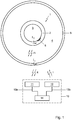
- Figure 1 shows a view of a system 10 according to the invention.
- the system 10 comprises a magnetic field receiver 11, a magnetic field source unit 12 and a processor 14 that is connected to the receiver 11 and the source 12 via data lines 13a-b, respectively.
- Figure 1 further shows a cross sectional view of a magnetisable conducting object 1 to be tested.
- the object 1 includes a pipe 2 enclosing a channel 3.
- the object 1 is mechanically shielded or covered by an enclosing magnetisable cylindrical layer 5 spaced from the object, thus defining an intermediate space 4 between the shielding layer 5 and the outer surface of the pipe 2.
- the pipe 2 is provided with a corrosion area 6 effectively locally narrowing the pipe thickness.
- the processor 14 provides a first signal for transmission to the magnetic field source unit 12 for abruptly changing the field strength of a primary magnetic field.
- the magnetic field source unit 12 is arranged for generating a primary magnetic field T for application exterior to the magnetisable layer 5.
- the primary magnetic field magnetization of the magnetisable conducting object 1 and the magnetisable layer 5 is obtained.
- the magnetic field source unit 12 Upon receipt of said first signal, the magnetic field source unit 12 abruptly changes the field strength of the primary magnetic field T, thereby inducing eddy currents in the magnetisable conducting object 1.
- the eddy currents generate a vanishing secondary magnetic field R that is received by the magnetic field receiver 11.
- the primary magnetic field that is applied exterior to the magnetisable layer may for example be in the form of a steady magnetic field which is suddenly switched off or in the form of a pulse (a magnetic fields which is switched on and shortly thereafter (for example after 1 second) is switched off).
- the magnetic field receiver 11 generates a second signal representing the vanishing secondary magnetic received field R.
- the second signal is input to the processor 14 for analyzing the temporal field strength of the received secondary magnetic field R, so that characteristics of the magnetisable conducting object 1 can be derived.
- Deriving object characteristics from said temporal field strength can be performed in various ways, e.g. by determining one or more bends in a field strength curve and/or by matching a field strength curve to a corresponding model.
- the primary field is turned on until a steady state is reached. Then, the primary magnetic field is switched off thereby abruptly changing the primary magnetic field and inducing the eddy currents I 1 ; I 2 in the layer 5 and in the object 1. As an alternative, the primary magnetic field is abruptly switched on to obtain the abrupt change in the primary magnetic field.
- the magnetisable layer needs not to be electrically conductive. If the layer is not conductive the method according to the invention can still be applied. According to an aspect of the invention, not eddy currents are suppressed, as the eddy currents would not have, due to the small thickness of the layer, a significant influence on the measurements of thicker magnetisable conducting objects. However, according to an aspect of the invention, the influence of the relaxation mechanism occurring in the shielding magnetisable layer is reduced or suppressed.
- the magnetic field source unit 12 in the shown embodiment comprises a single transmitting element for transmitting both the primary magnetic field and a tertiary magnetic field to be discussed hereafter.
- the single transmitting element is e.g. implemented as a coil. When an electrical current flows through the coil, a magnetic field is generated. In fact, the single transmitting element is controlled to generate the abruptly changing primary field and the oppositely oriented tertiary field.
- the magnetic field source unit 12 might include two separate transmitting elements wherein a first transmitting element transmits the primary magnetic field while a second transmitting element transmits the tertiary magnetic field.
- the magnetic field receiver 11 might be implemented as a coil.
- the secondary magnetic field can also be embodied otherwise, e.g. as a Hall sensor or a GMR sensor.
- the magnetisable layer 5 When the magnetic field source unit 12 is turned on to magnetise the object 1 under investigation also the magnetisable layer 5, optionally embodied as a galvanized sheeting, is magnetized. As soon as possible magnetic domains of the magnetisable layer 5 try to align with the applied field. To start the testing measurement, the primary magnetic field is switched off, after which the decay of the eddy currents in the investigated object 1 is measured by the receiver 11. At the same time the magnetic domains in the magnetisable layer 5 are released from their forced alignment and start to realign according to a locally preferred energy state. The realignment will take some time resulting in a changing magnetic field due to the domain realignment until a final remanence state is reached. The above-described physical phenomenon is known as relaxation of magnetic domains. The changing magnetic field results in an interaction signal IA due to magnetisable layer.
- Figure 2 shows a first diagram of received secondary magnetic fields I plotted as a function of time t[s] on a double logarithmic diagram.
- the object 1 is a pipe 2 shielded by a galvanized sheeting 5.
- a first curve 20 represents a normal situation wherein the pipe has a constant nominal thickness
- a second curve 21 represents a situation wherein the pipe thickness is reduced by circa 50%.
- the reduction of the wall thickness is still observable, a normal clear bend at a time instant corresponding with the wall thickness is obscured by the intermediate signal IA generated by the galvanized sheeting. Analysis of the curve tail at relatively high time instants becomes difficult.
- the relaxation mechanism is an unforced relaxation: there is no external driving force, only local energy gain or loss that drives the relaxation. This opens up the possibility to reduce the galvanized sheeting relaxation signal.
- the domains are forced to realign by means of an external force, the signal due to the reorientation can be reduced.
- a voltage is applied with opposite polarity as was needed to send the current through the coil. This enables to build a third, countering magnetic field inside the sheeting 5.
- the pulse is chosen in such a way that it contains as much energy as is needed to realign substantially half of the domains.
- the domains are of different size and need a slightly different force or energy to realign, substantially half of the domains can be realigned. Then, the further relaxation process will go on substantially unnoticed by the receiver system as the domains with opposite alignments will relax in a manner opposite to the realigned domains. As a result, the net sum of magnetic fields have a much smaller influence on the signal, in the ideal case the magnetic fields in the shielding layer have a net nil effect.
- the processor 14 provides a third signal for applying a transient tertiary magnetic field exterior to the magnetisable layer 5 when the field strength of the primary magnetic field abruptly changes, wherein the orientation of the primary and tertiary magnetic field, respectively, are mutually opposite. Said third signal is transmitted to the magnetic field source unit 12 to actually generate the transient tertiary magnetic field.
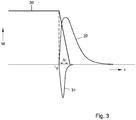
- Figure 3 shows a diagram of transmitted magnetic fields M as a function of time t.
- a primary magnetic field 30 is switched off at a time instant to to start the test measurement.
- the primary magnetic field 30 has a finite fall down time period ⁇ t.
- Figure 3 further shows a tertiary magnetic field 31 having opposite orientation with respect to the primary magnetic field orientation.
- the tertiary magnetic field is also called the reverse signal.
- Fig. 3 shows a secondary vanishing magnetic field 32 that is caused by the eddy currents in the object 1.
- the figure shows a scalar magnetic field component that represents a particular magnetic polarization.
- the secondary magnetic field curve is plotted on a scale that is different from the primary and tertiary magnetic field scales.
- the duration of the transient tertiary magnetic field is shorter than a time instant corresponding to a temporal field strength behaviour associated with a magnetisable conducting object characteristic. More specifically, the transient tertiary magnetic field vanishes before a tail of the secondary magnetic field starts, in which tail information of the magnetisable object 1 can be retrieved.
- the tertiary magnetic field is strong enough for substantially neutralizing temporal relaxation effects in the magnetisable layer 5. Also, the tertiary magnetic field is weak enough for avoiding substantial interaction with temporal eddy currents in the magnetisable conducting object 1.
- the transient tertiary magnetic field may be pulse shaped.
- the reverse pulse can be a voltage excitation of the transmitter coil, the build up of current through the coil and the magnetic field in the sheeting depends on the self-induction of the transmitter coil. This enables the control of the applied magnetic field by changing the period of the reverse pulse. Obviously, if the reverse pulse would be applied for a period as long as the secondary magnetic field, the complete signal will have been reversed and the reverse pulse does not have any improved measurement effect. Hence, the reverse pulse must be long enough to force at least part of the domains to realign and short enough so that is does not considerably changes the secondary magnetic field.
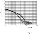
- Figure 4 shows a second diagram of received secondary magnetic fields I plotted as a function of time t[s] on a double logarithmic diagram.
- the diagram shows a first curve 40 representing a normal situation wherein the pipe has a constant nominal thickness, while a second curve 41 represents a situation wherein the pipe thickness is reduced by circa 50%.
- the curves 40, 41 have been obtained while applying the transient tertiary magnetic field.
- the effect of a reverse pulse of 1.38 ms on the before measured cases is shown.
- the tail of the galvanized sheeting is almost completely compensated.
- the bends due to the wall thickness of the object are clearly visible and comparable with the behaviour under aluminium sheeting.
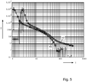
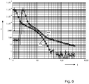
- Figures 5 and 6 show a third and fourth diagram, respectively, of received secondary magnetic fields I plotted as a function of time t[s] on a double logarithmic diagram.
- the object is a plate.
- the influence of the reverse pulse on the secondary magnetic field wherein the plate has a wall thickness of 12 mm is shown in Fig. 5 .
- a lift-off, i.e. a distance between the object 1 and the layer 5, of 75 mm is applied.
- a first curve 42 represents the situation without applied reverse pulse, while a second curve 43 represents the situation wherein the reverse pulse is applied according to an aspect of the invention. As shown, when applying the reverse pulse, the amplitude of the measured secondary magnetic field is reduced to approximately 55%.
- the tail due to the galvanized sheeting has been reduced by at least a factor of 20.
- Figure 6 shows similar curves 44, 45 where the secondary magnetic field amplitude is reduced to approximately 50%.
- the tail due to the galvanized sheeting has been reduced by at least a factor of 60.
- the long time tail in the signal arising from the relaxation of the domains in galvanized sheeting can be compensated for by means of a reverse voltage pulse of appropriate time length.
- the reverse pulse may reduce the amplitude of this tail by at a factor 20 to 60. Further, the pulse may reduce the signal of the object by roughly a factor of 2.
- the reverse pulse also reduces the induction signal of a probe, i.e. the signal without object 1 of layer 5 close to the probe, by roughly a factor of 2 compared to its value in a situation wherein no reverse pulse is applied.
- the method according to the invention enables non-destructive testing of magnetisable conducting objects that are shielded with a magnetisable layer wherein the effect of the magnetisable layer is virtually removed.
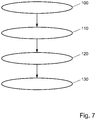
- Figure 7 shows a flow chart of an embodiment of the method according to the invention.
- the method is used for non-destructively testing a magnetisable conducting object mechanically shielded by a magnetisable layer.
- the method comprises the steps of abruptly changing (100) a field strength of a primary magnetic field that is applied exterior to the magnetisable layer, applying (110) a transient tertiary magnetic field exterior to the magnetisable layer when the field strength of the primary magnetic field abruptly changes, wherein the orientation of the primary and tertiary magnetic field, respectively, are mutually opposite, receiving (120) a vanishing secondary magnetic field generated by eddy currents induced by the changed field strength of the primary magnetic field, and analyzing (130) a temporal field strength of the received secondary magnetic field for deriving characteristics of the magnetisable object.
- the method of non-destructively testing a magnetisable object mechanically shielded by a magnetisable layer can be performed using dedicated hardware structures, such as FPGA and/or ASIC components. Otherwise, the method can also at least partially be performed using a computer program product comprising instructions for causing a processor of a computer system to perform the above described steps of the method according to the invention. All processing steps can in principle be performed on a single processor. However it is noted that at least one step can be performed on a separate processor, e.g. the step of receiving the vanishing secondary magnetic field and/or the step of analyzing the temporal field strength.
- the system and method according to the invention can not merely be applied to pipe segments surrounded by magnetisable layers, but also to other magnetisable conducting objects that are mechanically shielded by a magnetisable layer, such as a plate that is shielded by a plane sheet.
- a magnetisable layer such as a plate that is shielded by a plane sheet.
- the object might in principle have any geometry, such as a plate, a cylinder or a ball shell.
- the shielding magnetisable layer geometry may vary.
- the layer may e.g. be curved or substantially plane.
Landscapes
- Chemical & Material Sciences (AREA)
- Chemical Kinetics & Catalysis (AREA)
- Electrochemistry (AREA)
- Physics & Mathematics (AREA)
- Health & Medical Sciences (AREA)
- Life Sciences & Earth Sciences (AREA)
- Analytical Chemistry (AREA)
- Biochemistry (AREA)
- General Health & Medical Sciences (AREA)
- General Physics & Mathematics (AREA)
- Immunology (AREA)
- Pathology (AREA)
- Investigating Or Analyzing Materials By The Use Of Magnetic Means (AREA)
Description
- The invention relates to a method of non-clestructively testing a magnetisable conducting object mechanically shielded by a magnetisable layer, comprising the steps of abruptly changing a field strength of a primary magnetic field that is applied exterior to the magnetisable layer, receiving a vanishing secondary magnetic field generated by eddy currents induced by the changed field strength of the primary magnetic field, and analyzing a temporal field strength of the received secondary magnetic field for deriving characteristics of the magnetisable object.
- Such a method is known from
WO 98/ 34104 - Magnetic fields are widely used for non-destructively testing magnetisable conducting objects, such as pipe lines or metal plates, e.g. for corrosion or cracks. Thereto, the magnetisable object is probed by a primary magnetic field that is suddenly switched off, thereby inducing eddy currents in the object. Subsequently, the eddy currents generate a secondary magnetic field that may be measured to find characteristics of the tested object, such as local wall thickness.
- However, when the magnetisable object is mechanically shielded by a layer that is also magnetisable, it becomes difficult to retrieve object characteristics from the secondary magnetic field since eddy currents or other transient magnetic effects in the shielding layer cause an additional field that interferes with the secondary field.
- It is an object of the invention to provide a method according to the preamble wherein improved testing results may be obtained when testing magnetisable conducting objects that are mechanically shielded by a magnetisable layer. Thereto, the method according to the invention further comprises the step of applying a transient tertiary magnetic field exterior to the magnetisable layer when the field strength of the primary magnetic field abruptly changes, wherein the orientation of the primary and tertiary magnetic field, respectively, are mutually opposite.
- The invention is partly based in the insight that the eddy currents in the magnetisable layer generate a field that not merely superposes to the secondary magnetic field generated by the eddy currents in the object, but also interferes with the eddy current behaviour in the object itself. The interference with the eddy currents in the object blurs the secondary magnetic field and reduces the applicability. More importantly, relaxation mechanisms in the shielding layer interfere with the secondary magnetic field, thus providing a noisy signal that covers information of object characteristics.
- By applying an oppositely oriented tertiary magnetic field at the instant when the primary magnetic field abruptly changes, the effect of eddy currents in the magnetisable layer reduces dramatically. Magnetic domains in the magnetisable layer are realigned and neutralized so that further relaxations are prevented and have a reduced effect on the eddy currents in the object and on the secondary magnetic field to be measured. As such, the method according to the invention enables non-destructive testing of magnetisable conducting objects that are shielded with a magnetisable layer wherein the effect of the magnetisable layer is virtually removed.
- In a preferred embodiment according to the invention, the duration of the transient tertiary magnetic field is shorter than a time instant corresponding to a temporal field strength behaviour associated with a magnetisable object characteristic. As a result, object characteristics can be measured without substantial interference of the tertiary magnetic field with the object.
- Advantageously, the tertiary magnetic field is strong enough for substantially neutralizing relaxation processes in the magnetisable layer, so that influence on eddy currents creating the secondary magnetic field is minimized. Obviously, the tertiary magnetic field may be also be chosen smaller, e.g. to reduce the effects of the relaxation process in the magnetisable layer while improving the chance that the tertiary magnetic field does not interact with the eddy currents in the object.
- Further, the tertiary magnetic field may be chosen weak enough for avoiding substantial interaction with temporal eddy currents in the magnetisable conducting object, thus counteracting undesired interaction with the secondary magnetic field. The primary magnetic field that is applied exterior to the magnetisable layer may for example be in the form of a steady magnetic field which is suddenly switched off pulse or in the form of a pulse (a magnetic fields which is switched on and off).
- Further, the invention relates to a system.
- Additionally, the invention relates to a computer program product. A computer program product may comprise a set of computer executable instructions stored on a data carrier, such as a CD or a DVD. The set of computer executable instructions, which allow a programmable computer to carry out the method as defined above, may also be available for downloading from a remote server, for example via the Internet.
-
EP 1085 526 discloses a system wherein a probe coil is excited with an alternating current having a first frequency wherein a first complex impedance of the probe is measured. Furthermore a probe coil is excited with an alternating current having a second frequency wherein a second complex impedance of the probe is measured. The first impedance is phase rotated so that its polarity is 180° from the second complex impedance. The second complex impedance is added to the phase rotated first complex impedance.EP 1085 526 does not disclose receiving a vanishing secondary magnetic field generated by eddy currents induced by an abruptly changing field strength of a primary field wherein a transient tertiary magnetic field exterior to a magnetisable layer when the field strength of the primary magnetic field abruptly changes. - Other advantageous embodiments according to the invention are described in the following claims.
- By way of example only, embodiments of the present invention will now be described with reference to the accompanying figures in which
-
Fig. 1 shows a schematic view of a system according to the invention; -
Fig. 2 shows a first diagram of received secondary magnetic fields; -
Fig. 3 shows a diagram of transmitted magnetic fields; -
Fig. 4 shows a second diagram of received secondary magnetic fields; -
Fig. 5 shows a third diagram of received secondary magnetic fields; -
Fig. 6 shows a fourth diagram of received secondary magnetic fields; and -
Fig. 7 shows a flow chart of an embodiment of a method according to the invention. - The figures are merely schematic views of preferred embodiments according to the invention. In the figures, the same reference numbers refer to equal or corresponding parts.
-
Figure 1 shows a view of asystem 10 according to the invention. Thesystem 10 comprises amagnetic field receiver 11, a magneticfield source unit 12 and aprocessor 14 that is connected to thereceiver 11 and thesource 12 viadata lines 13a-b, respectively.Figure 1 further shows a cross sectional view of a magnetisable conductingobject 1 to be tested. Theobject 1 includes apipe 2 enclosing achannel 3. Theobject 1 is mechanically shielded or covered by an enclosing magnetisablecylindrical layer 5 spaced from the object, thus defining anintermediate space 4 between theshielding layer 5 and the outer surface of thepipe 2. Thepipe 2 is provided with acorrosion area 6 effectively locally narrowing the pipe thickness. - During operation of the
system 1 according to the invention, theprocessor 14 provides a first signal for transmission to the magneticfield source unit 12 for abruptly changing the field strength of a primary magnetic field. The magneticfield source unit 12 is arranged for generating a primary magnetic field T for application exterior to themagnetisable layer 5. By applying the primary magnetic field, magnetization of the magnetisable conductingobject 1 and themagnetisable layer 5 is obtained. Upon receipt of said first signal, the magneticfield source unit 12 abruptly changes the field strength of the primary magnetic field T, thereby inducing eddy currents in the magnetisable conductingobject 1. The eddy currents generate a vanishing secondary magnetic field R that is received by themagnetic field receiver 11. The primary magnetic field that is applied exterior to the magnetisable layer may for example be in the form of a steady magnetic field which is suddenly switched off or in the form of a pulse (a magnetic fields which is switched on and shortly thereafter (for example after 1 second) is switched off). Then, themagnetic field receiver 11 generates a second signal representing the vanishing secondary magnetic received field R. The second signal is input to theprocessor 14 for analyzing the temporal field strength of the received secondary magnetic field R, so that characteristics of the magnetisable conductingobject 1 can be derived. - Deriving object characteristics from said temporal field strength can be performed in various ways, e.g. by determining one or more bends in a field strength curve and/or by matching a field strength curve to a corresponding model.
- In a practical embodiment, the primary field is turned on until a steady state is reached. Then, the primary magnetic field is switched off thereby abruptly changing the primary magnetic field and inducing the eddy currents I1; I2 in the
layer 5 and in theobject 1. As an alternative, the primary magnetic field is abruptly switched on to obtain the abrupt change in the primary magnetic field. - It is noted that the magnetisable layer needs not to be electrically conductive. If the layer is not conductive the method according to the invention can still be applied. According to an aspect of the invention, not eddy currents are suppressed, as the eddy currents would not have, due to the small thickness of the layer, a significant influence on the measurements of thicker magnetisable conducting objects. However, according to an aspect of the invention, the influence of the relaxation mechanism occurring in the shielding magnetisable layer is reduced or suppressed.
- It is further noted that the magnetic
field source unit 12 in the shown embodiment comprises a single transmitting element for transmitting both the primary magnetic field and a tertiary magnetic field to be discussed hereafter. The single transmitting element is e.g. implemented as a coil. When an electrical current flows through the coil, a magnetic field is generated. In fact, the single transmitting element is controlled to generate the abruptly changing primary field and the oppositely oriented tertiary field. However, as an alternative, the magneticfield source unit 12 might include two separate transmitting elements wherein a first transmitting element transmits the primary magnetic field while a second transmitting element transmits the tertiary magnetic field. - Also the
magnetic field receiver 11 might be implemented as a coil. Obviously, the secondary magnetic field can also be embodied otherwise, e.g. as a Hall sensor or a GMR sensor. - When the magnetic
field source unit 12 is turned on to magnetise theobject 1 under investigation also themagnetisable layer 5, optionally embodied as a galvanized sheeting, is magnetized. As soon as possible magnetic domains of themagnetisable layer 5 try to align with the applied field. To start the testing measurement, the primary magnetic field is switched off, after which the decay of the eddy currents in the investigatedobject 1 is measured by thereceiver 11. At the same time the magnetic domains in themagnetisable layer 5 are released from their forced alignment and start to realign according to a locally preferred energy state. The realignment will take some time resulting in a changing magnetic field due to the domain realignment until a final remanence state is reached. The above-described physical phenomenon is known as relaxation of magnetic domains. The changing magnetic field results in an interaction signal IA due to magnetisable layer. -
Figure 2 shows a first diagram of received secondary magnetic fields I plotted as a function of time t[s] on a double logarithmic diagram. Theobject 1 is apipe 2 shielded by agalvanized sheeting 5. Afirst curve 20 represents a normal situation wherein the pipe has a constant nominal thickness, while asecond curve 21 represents a situation wherein the pipe thickness is reduced by circa 50%. Although for the shown curves, the reduction of the wall thickness is still observable, a normal clear bend at a time instant corresponding with the wall thickness is obscured by the intermediate signal IA generated by the galvanized sheeting. Analysis of the curve tail at relatively high time instants becomes difficult. Obviously, the bend in the curve due to the wall thickness would become invisible for thicker materials, as the curve decays according to tγ1 , where γ1 ≈ -1.5 and a relaxation signal decays according to tγ2 where γ2 ≈ -1. - Typically, the relaxation mechanism is an unforced relaxation: there is no external driving force, only local energy gain or loss that drives the relaxation. This opens up the possibility to reduce the galvanized sheeting relaxation signal. When the domains are forced to realign by means of an external force, the signal due to the reorientation can be reduced. To accomplish this, directly after switching off the current through the
transmitter coil 12, a voltage is applied with opposite polarity as was needed to send the current through the coil. This enables to build a third, countering magnetic field inside thesheeting 5. When the third magnetic field becomes high enough, the domains are forced to realign again. Preferably, the pulse is chosen in such a way that it contains as much energy as is needed to realign substantially half of the domains. Since the domains are of different size and need a slightly different force or energy to realign, substantially half of the domains can be realigned. Then, the further relaxation process will go on substantially unnoticed by the receiver system as the domains with opposite alignments will relax in a manner opposite to the realigned domains. As a result, the net sum of magnetic fields have a much smaller influence on the signal, in the ideal case the magnetic fields in the shielding layer have a net nil effect. - Thereto, according to an aspect of the invention, the
processor 14 provides a third signal for applying a transient tertiary magnetic field exterior to themagnetisable layer 5 when the field strength of the primary magnetic field abruptly changes, wherein the orientation of the primary and tertiary magnetic field, respectively, are mutually opposite. Said third signal is transmitted to the magneticfield source unit 12 to actually generate the transient tertiary magnetic field. -
Figure 3 shows a diagram of transmitted magnetic fields M as a function of time t. A primarymagnetic field 30 is switched off at a time instant to to start the test measurement. The primarymagnetic field 30 has a finite fall down time period Δt.Figure 3 further shows a tertiarymagnetic field 31 having opposite orientation with respect to the primary magnetic field orientation. As an example, when the primarymagnetic field 30 has a positive sign, the tertiarymagnetic field 31 has a negative sign, and vice versa. The tertiary magnetic field is also called the reverse signal. In addition,Fig. 3 shows a secondary vanishingmagnetic field 32 that is caused by the eddy currents in theobject 1. In this respect it is noted that the figure shows a scalar magnetic field component that represents a particular magnetic polarization. It is further noted that the secondary magnetic field curve is plotted on a scale that is different from the primary and tertiary magnetic field scales. - The duration of the transient tertiary magnetic field is shorter than a time instant corresponding to a temporal field strength behaviour associated with a magnetisable conducting object characteristic. More specifically, the transient tertiary magnetic field vanishes before a tail of the secondary magnetic field starts, in which tail information of the
magnetisable object 1 can be retrieved. - Further, the tertiary magnetic field is strong enough for substantially neutralizing temporal relaxation effects in the
magnetisable layer 5. Also, the tertiary magnetic field is weak enough for avoiding substantial interaction with temporal eddy currents in themagnetisable conducting object 1. - The transient tertiary magnetic field may be pulse shaped. As the reverse pulse can be a voltage excitation of the transmitter coil, the build up of current through the coil and the magnetic field in the sheeting depends on the self-induction of the transmitter coil. This enables the control of the applied magnetic field by changing the period of the reverse pulse. Obviously, if the reverse pulse would be applied for a period as long as the secondary magnetic field, the complete signal will have been reversed and the reverse pulse does not have any improved measurement effect. Hence, the reverse pulse must be long enough to force at least part of the domains to realign and short enough so that is does not considerably changes the secondary magnetic field.
-
Figure 4 shows a second diagram of received secondary magnetic fields I plotted as a function of time t[s] on a double logarithmic diagram. Again, the diagram shows afirst curve 40 representing a normal situation wherein the pipe has a constant nominal thickness, while asecond curve 41 represents a situation wherein the pipe thickness is reduced by circa 50%. Here, thecurves -
Figures 5 and6 show a third and fourth diagram, respectively, of received secondary magnetic fields I plotted as a function of time t[s] on a double logarithmic diagram. Here, the object is a plate. The influence of the reverse pulse on the secondary magnetic field wherein the plate has a wall thickness of 12 mm is shown inFig. 5 . A lift-off, i.e. a distance between theobject 1 and thelayer 5, of 75 mm is applied. Afirst curve 42 represents the situation without applied reverse pulse, while asecond curve 43 represents the situation wherein the reverse pulse is applied according to an aspect of the invention. As shown, when applying the reverse pulse, the amplitude of the measured secondary magnetic field is reduced to approximately 55%. The tail due to the galvanized sheeting has been reduced by at least a factor of 20. A comparable situation arise for the measurements on a wall thickness of 6 mm.Figure 6 showssimilar curves - The long time tail in the signal arising from the relaxation of the domains in galvanized sheeting can be compensated for by means of a reverse voltage pulse of appropriate time length. The reverse pulse may reduce the amplitude of this tail by at a
factor 20 to 60. Further, the pulse may reduce the signal of the object by roughly a factor of 2. The reverse pulse also reduces the induction signal of a probe, i.e. the signal withoutobject 1 oflayer 5 close to the probe, by roughly a factor of 2 compared to its value in a situation wherein no reverse pulse is applied. The method according to the invention enables non-destructive testing of magnetisable conducting objects that are shielded with a magnetisable layer wherein the effect of the magnetisable layer is virtually removed. -
Figure 7 shows a flow chart of an embodiment of the method according to the invention. The method is used for non-destructively testing a magnetisable conducting object mechanically shielded by a magnetisable layer. The method comprises the steps of abruptly changing (100) a field strength of a primary magnetic field that is applied exterior to the magnetisable layer, applying (110) a transient tertiary magnetic field exterior to the magnetisable layer when the field strength of the primary magnetic field abruptly changes, wherein the orientation of the primary and tertiary magnetic field, respectively, are mutually opposite, receiving (120) a vanishing secondary magnetic field generated by eddy currents induced by the changed field strength of the primary magnetic field, and analyzing (130) a temporal field strength of the received secondary magnetic field for deriving characteristics of the magnetisable object. - The method of non-destructively testing a magnetisable object mechanically shielded by a magnetisable layer can be performed using dedicated hardware structures, such as FPGA and/or ASIC components. Otherwise, the method can also at least partially be performed using a computer program product comprising instructions for causing a processor of a computer system to perform the above described steps of the method according to the invention. All processing steps can in principle be performed on a single processor. However it is noted that at least one step can be performed on a separate processor, e.g. the step of receiving the vanishing secondary magnetic field and/or the step of analyzing the temporal field strength.
- The invention is not restricted to the embodiments described herein. It will be understood that many variants are possible.
- The system and method according to the invention can not merely be applied to pipe segments surrounded by magnetisable layers, but also to other magnetisable conducting objects that are mechanically shielded by a magnetisable layer, such as a plate that is shielded by a plane sheet. In this context it is noted that the object might in principle have any geometry, such as a plate, a cylinder or a ball shell. Also the shielding magnetisable layer geometry may vary. The layer may e.g. be curved or substantially plane.
- Other such variants will be obvious for the person skilled in the art and are considered to lie within the scope of the invention as formulated in the following claims.
Claims (9)
- A method of non-destructively testing a magnetisable conducting object (1) mechanically shielded by a magnetisable layer (5), comprising the steps of:- abruptly changing a field strength of a primary magnetic field (30) that is applied exterior to the magnetisable layer thereby inducing eddy currents in the object.- receiving a vanishing secondary magnetic field (32) generated by eddy currents induced by the changed field strength of the primary magnetic field, and- analyzing a temporal field strength of the received secondary magnetic field for deriving characteristics of the magnetisable conducting object,characterised in that the method further comprises the step of:- applying a transient tertiary magnetic field (31) exterior to the magnetisable layer when the field strength of the primary magnetic field abruptly changes, wherein the orientation of the primary and tertiary magnetic field, respectively, are mutually opposite.
- A method according to claim 1, wherein the duration of the transient tertiary magnetic field is shorter than a time instant corresponding to a temporal field strength behaviour associated with a magnetisable conducting object characteristic.
- A method according to claim 1 and/or 2, wherein the tertiary magnetic field is strong enough for substantially neutralizing temporal relaxation processes in the magnetisable layer.
- A method according to any of the previous claims, wherein the tertiary magnetic field is weak enough for avoiding substantial interaction with temporal eddy currents in the magnetisable conducting object.
- A method according to any of the previous claims, wherein the step of abruptly changing the primary magnetic field strength includes switching off the primary magnetic field.
- A system (10) for non-destructively testing a magnetisable conducting object (1) mechanically shielded by a magnetisable layer (5), comprising:- a magnetic field source unit (12) for generating a primary magnetic field that is applied exterior to the magnetisable layer thereby inducing eddy currents in the object.- a magnetic field receiver (11) for receiving a vanishing secondary magnetic field generated by eddy currents, and- a processor (14) arranged for- transmitting a first signal to the magnetic field source unit for abruptly changing the field strength of the primary magnetic field,- inputting a second signal from the magnetic field receiver, the second signal representing the vanishing secondary magnetic received field generated by eddy currents induced by the changed field strength of the primary magnetic field, and- analyzing a temporal field strength of the received secondary magnetic field for deriving characteristics of the magnetisable conducting object,characterised in that the processor (14) is further arranged for- transmitting a third signal to the magnetic field source unit for applying a transient tertiary magnetic field exterior to the magnetisable layer when the field strength of the primary magnetic field abruptly changes, wherein the orientation of the primary and tertiary magnetic field, respectively, are mutually opposite.
- A system according to claim 6, wherein the magnetic field source unit (12) comprises a single transmitting element for transmitting both the primary magnetic field and the tertiary magnetic field.
- A system according to claim 6, wherein the magnetic field source unit (12) comprises two separate transmitting elements for transmitting the primary magnetic field and the tertiary magnetic field, respectively.
- A computer program product for non-destructively testing a magnetisable conducting object (1) mechanically shielded by a magnetisable layer (5), which computer program product comprises instructions for causing a processor (14) to perform the steps of:- providing a first signal to a magnetic field source unit (12) for abruptly changing a field strength of a primary magnetic field that is applied exterior to the magnetisable layer,- inputting from a magnetic field receiver (11) a second signal representing a vanishing secondary magnetic received field generated by eddy currents induced by the changed field strength of the primary magnetic field, and- analyzing a temporal field strength of the received secondary magnetic field for deriving characteristics of the magnetisable conducting object,characterised in that the computer program product further comprises instructions for causing the processor (14) to perform the step of:- providing a third signal to the magnetic field source unit (12) for applying a transient tertiary magnetic field exterior to the magnetisable layer when the field strength of the primary magnetic field abruptly changes, wherein the orientation of the primary and tertiary magnetic field, respectively, are mutually opposite.
Applications Claiming Priority (1)
| Application Number | Priority Date | Filing Date | Title |
|---|---|---|---|
| NL2002921A NL2002921C2 (en) | 2009-05-25 | 2009-05-25 | A METHOD OR NON-DESTRUCTIVELY TESTING, A SYSTEM AND A COMPUTER PROGRAM PRODUCT. |
Publications (2)
| Publication Number | Publication Date |
|---|---|
| EP2256489A1 EP2256489A1 (en) | 2010-12-01 |
| EP2256489B1 true EP2256489B1 (en) | 2019-06-26 |
Family
ID=42035867
Family Applications (1)
| Application Number | Title | Priority Date | Filing Date |
|---|---|---|---|
| EP10163776.7A Active EP2256489B1 (en) | 2009-05-25 | 2010-05-25 | Method and apparatus for non-destructive testing using eddy currents. |
Country Status (6)
| Country | Link |
|---|---|
| US (1) | US8547089B2 (en) |
| EP (1) | EP2256489B1 (en) |
| JP (1) | JP5681390B2 (en) |
| AU (1) | AU2010202114B2 (en) |
| CA (1) | CA2705119A1 (en) |
| NL (1) | NL2002921C2 (en) |
Families Citing this family (5)
| Publication number | Priority date | Publication date | Assignee | Title |
|---|---|---|---|---|
| US10073058B2 (en) | 2015-02-11 | 2018-09-11 | Structural Integrity Associates | Dynamic pulsed eddy current probe |
| US10895555B2 (en) | 2015-03-30 | 2021-01-19 | Structural Integrity Associates, Inc. | System for in-line inspection using a dynamic pulsed eddy current probe and method thereof |
| CA2951848C (en) | 2015-12-15 | 2024-01-16 | Eddyfi Ndt Inc. | Pulsed eddy current testing with dual-purpose coils |
| JP2019039677A (en) * | 2017-08-22 | 2019-03-14 | 九州電力株式会社 | Heat retention piping flaw detection apparatus and heat retention piping flaw detection method |
| CN120972060B (en) * | 2025-10-22 | 2026-01-30 | 杭州极弱磁场国家重大科技基础设施研究院 | Residual magnetism state detection method and device, electronic equipment and readable storage medium |
Family Cites Families (12)
| Publication number | Priority date | Publication date | Assignee | Title |
|---|---|---|---|---|
| US3597678A (en) * | 1968-12-24 | 1971-08-03 | Williams Brothers Co | Apparatus for sensing thickness variations, discontinuities, and the like in elongated steel structures by measuring variations in magnetic properties utilizing a flux gate |
| BE790091A (en) * | 1971-10-14 | 1973-04-13 | Philips Nv | MAGNETIC DOMAIN DEVICE |
| US4929898A (en) * | 1987-12-17 | 1990-05-29 | Atlantic Richfield | Transient electromagnetic method for detecting irregularities on conductive containers |
| JP3072304B2 (en) * | 1994-09-14 | 2000-07-31 | 株式会社関電工 | Metal detection method |
| NL1005160C2 (en) * | 1997-01-31 | 1998-08-03 | Roentgen Tech Dienst Bv | Device for determining properties of an electrically conductive object. |
| US6366083B1 (en) * | 1999-09-17 | 2002-04-02 | Framatome Anp Inc. | Method for measuring the thickness of oxide layer underlying crud layer containing ferromagnetic material on nuclear fuel rods |
| US6570379B2 (en) * | 2000-08-24 | 2003-05-27 | Shell Oil Company | Method for inspecting an object of electrically conducting material |
| US7005851B2 (en) * | 2003-09-30 | 2006-02-28 | General Electric Company | Methods and apparatus for inspection utilizing pulsed eddy current |
| JP4764248B2 (en) * | 2006-05-15 | 2011-08-31 | 本田技研工業株式会社 | Control device for fuel injection device |
| CA2566933C (en) * | 2006-10-17 | 2013-09-24 | Athena Industrial Technologies Inc. | Inspection apparatus and method |
| JP5213475B2 (en) * | 2008-02-18 | 2013-06-19 | 日本高圧電気株式会社 | Measuring apparatus and measuring method |
| JP5243175B2 (en) * | 2008-10-01 | 2013-07-24 | 株式会社日立製作所 | Pulse excitation type eddy current flaw detection method and flaw detection apparatus |
-
2009
- 2009-05-25 NL NL2002921A patent/NL2002921C2/en not_active IP Right Cessation
-
2010
- 2010-05-21 CA CA2705119A patent/CA2705119A1/en not_active Abandoned
- 2010-05-24 JP JP2010131442A patent/JP5681390B2/en not_active Expired - Fee Related
- 2010-05-25 US US12/801,159 patent/US8547089B2/en not_active Expired - Fee Related
- 2010-05-25 AU AU2010202114A patent/AU2010202114B2/en not_active Ceased
- 2010-05-25 EP EP10163776.7A patent/EP2256489B1/en active Active
Non-Patent Citations (1)
| Title |
|---|
| None * |
Also Published As
| Publication number | Publication date |
|---|---|
| AU2010202114A1 (en) | 2010-12-09 |
| EP2256489A1 (en) | 2010-12-01 |
| AU2010202114B2 (en) | 2014-03-06 |
| NL2002921C2 (en) | 2010-11-30 |
| CA2705119A1 (en) | 2010-11-25 |
| US20100315077A1 (en) | 2010-12-16 |
| JP5681390B2 (en) | 2015-03-04 |
| US8547089B2 (en) | 2013-10-01 |
| JP2010271323A (en) | 2010-12-02 |
Similar Documents
| Publication | Publication Date | Title |
|---|---|---|
| EP0967490B1 (en) | Method for eliminating ringing during a nuclear magnetic resonance borehole measurement | |
| Wilson et al. | Pulsed electromagnetic methods for defect detection and characterisation | |
| Dutton et al. | A new magnetic configuration for a small in-plane electromagnetic acoustic transducer applied to laser-ultrasound measurements: Modelling and validation | |
| Jian et al. | Coupling mechanism of an EMAT | |
| US8547089B2 (en) | Method of non-destructively testing, a system and a computer program product | |
| JP7414260B2 (en) | Electromagnetic ultrasound transducer (EMAT) for corrosion mapping | |
| CN108802185A (en) | Metal material defects detection sensor based on impulse eddy current and electromagnetic acoustic | |
| US20090084185A1 (en) | Electromagnetic acoustic transducer with cross-talk elimination | |
| CN103760224A (en) | Spacecraft nondestructive detection sensor and nondestructive detection system | |
| US12332211B2 (en) | Method for determining a materials characteristic value of magnetizable metal bodies by means of a micromagnetic sensor assembly, and corresponding sensor assembly | |
| US6246237B1 (en) | Method of and apparatus for testing a sample | |
| USH2177H1 (en) | Cancellation of ringing in magnetic resonance utilizing a composite pulse | |
| Morrison et al. | Lift-off compensation for improved accuracy in ultrasonic lamb wave velocity measurements using electromagnetic acoustic transducers (EMATs) | |
| JP6551885B2 (en) | Nondestructive inspection device and nondestructive inspection method | |
| JP3608423B2 (en) | Electromagnetic ultrasonic measurement method and apparatus | |
| JP6817628B2 (en) | Vibration radar device and data analysis device | |
| US6411105B1 (en) | Nondestructive detection of steel surface corrosion | |
| Singh et al. | Thickness evaluation of aluminium plate using pulsed eddy current technique | |
| RU2561250C2 (en) | Method of detection of defects on surfaces of ferromagnetic materials and products and device for its implementation | |
| Ding et al. | An Improved Time-Frequency Identification Method for Pipeline Weld EMAE Aliasing Modes With a Focused Electromagnetic Excitation Device | |
| US6392421B1 (en) | Spectral EM frequency metallic thickness measurement using metallic transparencies | |
| JP2009300316A (en) | Electromagnetic ultrasonic sensor | |
| Gurevich et al. | EMA recording of ultrasound lamb waves excited by laser nanopulses | |
| US20220128500A1 (en) | Inductive measuring apparatus and calibration device and method | |
| Atavin et al. | Plotting and analysis of hodographs for studying the electrophysical parameters of objects using attachable eddy-current transducers |
Legal Events
| Date | Code | Title | Description |
|---|---|---|---|
| PUAI | Public reference made under article 153(3) epc to a published international application that has entered the european phase |
Free format text: ORIGINAL CODE: 0009012 |
|
| AK | Designated contracting states |
Kind code of ref document: A1 Designated state(s): AL AT BE BG CH CY CZ DE DK EE ES FI FR GB GR HR HU IE IS IT LI LT LU LV MC MK MT NL NO PL PT RO SE SI SK SM TR |
|
| AX | Request for extension of the european patent |
Extension state: BA ME RS |
|
| 17P | Request for examination filed |
Effective date: 20110601 |
|
| GRAP | Despatch of communication of intention to grant a patent |
Free format text: ORIGINAL CODE: EPIDOSNIGR1 |
|
| STAA | Information on the status of an ep patent application or granted ep patent |
Free format text: STATUS: GRANT OF PATENT IS INTENDED |
|
| INTG | Intention to grant announced |
Effective date: 20190103 |
|
| GRAS | Grant fee paid |
Free format text: ORIGINAL CODE: EPIDOSNIGR3 |
|
| GRAA | (expected) grant |
Free format text: ORIGINAL CODE: 0009210 |
|
| STAA | Information on the status of an ep patent application or granted ep patent |
Free format text: STATUS: THE PATENT HAS BEEN GRANTED |
|
| AK | Designated contracting states |
Kind code of ref document: B1 Designated state(s): AL AT BE BG CH CY CZ DE DK EE ES FI FR GB GR HR HU IE IS IT LI LT LU LV MC MK MT NL NO PL PT RO SE SI SK SM TR |
|
| REG | Reference to a national code |
Ref country code: GB Ref legal event code: FG4D |
|
| REG | Reference to a national code |
Ref country code: CH Ref legal event code: EP |
|
| REG | Reference to a national code |
Ref country code: AT Ref legal event code: REF Ref document number: 1148882 Country of ref document: AT Kind code of ref document: T Effective date: 20190715 |
|
| REG | Reference to a national code |
Ref country code: DE Ref legal event code: R096 Ref document number: 602010059649 Country of ref document: DE |
|
| REG | Reference to a national code |
Ref country code: IE Ref legal event code: FG4D |
|
| REG | Reference to a national code |
Ref country code: NL Ref legal event code: MP Effective date: 20190626 |
|
| PG25 | Lapsed in a contracting state [announced via postgrant information from national office to epo] |
Ref country code: NO Free format text: LAPSE BECAUSE OF FAILURE TO SUBMIT A TRANSLATION OF THE DESCRIPTION OR TO PAY THE FEE WITHIN THE PRESCRIBED TIME-LIMIT Effective date: 20190926 Ref country code: FI Free format text: LAPSE BECAUSE OF FAILURE TO SUBMIT A TRANSLATION OF THE DESCRIPTION OR TO PAY THE FEE WITHIN THE PRESCRIBED TIME-LIMIT Effective date: 20190626 Ref country code: SE Free format text: LAPSE BECAUSE OF FAILURE TO SUBMIT A TRANSLATION OF THE DESCRIPTION OR TO PAY THE FEE WITHIN THE PRESCRIBED TIME-LIMIT Effective date: 20190626 Ref country code: AL Free format text: LAPSE BECAUSE OF FAILURE TO SUBMIT A TRANSLATION OF THE DESCRIPTION OR TO PAY THE FEE WITHIN THE PRESCRIBED TIME-LIMIT Effective date: 20190626 Ref country code: LT Free format text: LAPSE BECAUSE OF FAILURE TO SUBMIT A TRANSLATION OF THE DESCRIPTION OR TO PAY THE FEE WITHIN THE PRESCRIBED TIME-LIMIT Effective date: 20190626 Ref country code: HR Free format text: LAPSE BECAUSE OF FAILURE TO SUBMIT A TRANSLATION OF THE DESCRIPTION OR TO PAY THE FEE WITHIN THE PRESCRIBED TIME-LIMIT Effective date: 20190626 |
|
| REG | Reference to a national code |
Ref country code: LT Ref legal event code: MG4D |
|
| PG25 | Lapsed in a contracting state [announced via postgrant information from national office to epo] |
Ref country code: GR Free format text: LAPSE BECAUSE OF FAILURE TO SUBMIT A TRANSLATION OF THE DESCRIPTION OR TO PAY THE FEE WITHIN THE PRESCRIBED TIME-LIMIT Effective date: 20190927 Ref country code: LV Free format text: LAPSE BECAUSE OF FAILURE TO SUBMIT A TRANSLATION OF THE DESCRIPTION OR TO PAY THE FEE WITHIN THE PRESCRIBED TIME-LIMIT Effective date: 20190626 Ref country code: BG Free format text: LAPSE BECAUSE OF FAILURE TO SUBMIT A TRANSLATION OF THE DESCRIPTION OR TO PAY THE FEE WITHIN THE PRESCRIBED TIME-LIMIT Effective date: 20190926 |
|
| REG | Reference to a national code |
Ref country code: AT Ref legal event code: MK05 Ref document number: 1148882 Country of ref document: AT Kind code of ref document: T Effective date: 20190626 |
|
| PG25 | Lapsed in a contracting state [announced via postgrant information from national office to epo] |
Ref country code: RO Free format text: LAPSE BECAUSE OF FAILURE TO SUBMIT A TRANSLATION OF THE DESCRIPTION OR TO PAY THE FEE WITHIN THE PRESCRIBED TIME-LIMIT Effective date: 20190626 Ref country code: NL Free format text: LAPSE BECAUSE OF FAILURE TO SUBMIT A TRANSLATION OF THE DESCRIPTION OR TO PAY THE FEE WITHIN THE PRESCRIBED TIME-LIMIT Effective date: 20190626 Ref country code: CZ Free format text: LAPSE BECAUSE OF FAILURE TO SUBMIT A TRANSLATION OF THE DESCRIPTION OR TO PAY THE FEE WITHIN THE PRESCRIBED TIME-LIMIT Effective date: 20190626 Ref country code: AT Free format text: LAPSE BECAUSE OF FAILURE TO SUBMIT A TRANSLATION OF THE DESCRIPTION OR TO PAY THE FEE WITHIN THE PRESCRIBED TIME-LIMIT Effective date: 20190626 Ref country code: EE Free format text: LAPSE BECAUSE OF FAILURE TO SUBMIT A TRANSLATION OF THE DESCRIPTION OR TO PAY THE FEE WITHIN THE PRESCRIBED TIME-LIMIT Effective date: 20190626 Ref country code: PT Free format text: LAPSE BECAUSE OF FAILURE TO SUBMIT A TRANSLATION OF THE DESCRIPTION OR TO PAY THE FEE WITHIN THE PRESCRIBED TIME-LIMIT Effective date: 20191028 Ref country code: SK Free format text: LAPSE BECAUSE OF FAILURE TO SUBMIT A TRANSLATION OF THE DESCRIPTION OR TO PAY THE FEE WITHIN THE PRESCRIBED TIME-LIMIT Effective date: 20190626 |
|
| PG25 | Lapsed in a contracting state [announced via postgrant information from national office to epo] |
Ref country code: IT Free format text: LAPSE BECAUSE OF FAILURE TO SUBMIT A TRANSLATION OF THE DESCRIPTION OR TO PAY THE FEE WITHIN THE PRESCRIBED TIME-LIMIT Effective date: 20190626 Ref country code: SM Free format text: LAPSE BECAUSE OF FAILURE TO SUBMIT A TRANSLATION OF THE DESCRIPTION OR TO PAY THE FEE WITHIN THE PRESCRIBED TIME-LIMIT Effective date: 20190626 Ref country code: IS Free format text: LAPSE BECAUSE OF FAILURE TO SUBMIT A TRANSLATION OF THE DESCRIPTION OR TO PAY THE FEE WITHIN THE PRESCRIBED TIME-LIMIT Effective date: 20191026 Ref country code: ES Free format text: LAPSE BECAUSE OF FAILURE TO SUBMIT A TRANSLATION OF THE DESCRIPTION OR TO PAY THE FEE WITHIN THE PRESCRIBED TIME-LIMIT Effective date: 20190626 |
|
| PG25 | Lapsed in a contracting state [announced via postgrant information from national office to epo] |
Ref country code: TR Free format text: LAPSE BECAUSE OF FAILURE TO SUBMIT A TRANSLATION OF THE DESCRIPTION OR TO PAY THE FEE WITHIN THE PRESCRIBED TIME-LIMIT Effective date: 20190626 |
|
| PG25 | Lapsed in a contracting state [announced via postgrant information from national office to epo] |
Ref country code: DK Free format text: LAPSE BECAUSE OF FAILURE TO SUBMIT A TRANSLATION OF THE DESCRIPTION OR TO PAY THE FEE WITHIN THE PRESCRIBED TIME-LIMIT Effective date: 20190626 Ref country code: PL Free format text: LAPSE BECAUSE OF FAILURE TO SUBMIT A TRANSLATION OF THE DESCRIPTION OR TO PAY THE FEE WITHIN THE PRESCRIBED TIME-LIMIT Effective date: 20190626 |
|
| PG25 | Lapsed in a contracting state [announced via postgrant information from national office to epo] |
Ref country code: IS Free format text: LAPSE BECAUSE OF FAILURE TO SUBMIT A TRANSLATION OF THE DESCRIPTION OR TO PAY THE FEE WITHIN THE PRESCRIBED TIME-LIMIT Effective date: 20200224 |
|
| REG | Reference to a national code |
Ref country code: DE Ref legal event code: R097 Ref document number: 602010059649 Country of ref document: DE |
|
| PLBE | No opposition filed within time limit |
Free format text: ORIGINAL CODE: 0009261 |
|
| STAA | Information on the status of an ep patent application or granted ep patent |
Free format text: STATUS: NO OPPOSITION FILED WITHIN TIME LIMIT |
|
| PG2D | Information on lapse in contracting state deleted |
Ref country code: IS |
|
| 26N | No opposition filed |
Effective date: 20200603 |
|
| PG25 | Lapsed in a contracting state [announced via postgrant information from national office to epo] |
Ref country code: SI Free format text: LAPSE BECAUSE OF FAILURE TO SUBMIT A TRANSLATION OF THE DESCRIPTION OR TO PAY THE FEE WITHIN THE PRESCRIBED TIME-LIMIT Effective date: 20190626 |
|
| PG25 | Lapsed in a contracting state [announced via postgrant information from national office to epo] |
Ref country code: LI Free format text: LAPSE BECAUSE OF NON-PAYMENT OF DUE FEES Effective date: 20200531 Ref country code: CH Free format text: LAPSE BECAUSE OF NON-PAYMENT OF DUE FEES Effective date: 20200531 Ref country code: MC Free format text: LAPSE BECAUSE OF FAILURE TO SUBMIT A TRANSLATION OF THE DESCRIPTION OR TO PAY THE FEE WITHIN THE PRESCRIBED TIME-LIMIT Effective date: 20190626 |
|
| PGFP | Annual fee paid to national office [announced via postgrant information from national office to epo] |
Ref country code: DE Payment date: 20201026 Year of fee payment: 11 |
|
| REG | Reference to a national code |
Ref country code: BE Ref legal event code: MM Effective date: 20200531 |
|
| GBPC | Gb: european patent ceased through non-payment of renewal fee |
Effective date: 20200525 |
|
| PG25 | Lapsed in a contracting state [announced via postgrant information from national office to epo] |
Ref country code: LU Free format text: LAPSE BECAUSE OF NON-PAYMENT OF DUE FEES Effective date: 20200525 |
|
| PG25 | Lapsed in a contracting state [announced via postgrant information from national office to epo] |
Ref country code: GB Free format text: LAPSE BECAUSE OF NON-PAYMENT OF DUE FEES Effective date: 20200525 Ref country code: FR Free format text: LAPSE BECAUSE OF NON-PAYMENT OF DUE FEES Effective date: 20200531 Ref country code: IE Free format text: LAPSE BECAUSE OF NON-PAYMENT OF DUE FEES Effective date: 20200525 |
|
| PG25 | Lapsed in a contracting state [announced via postgrant information from national office to epo] |
Ref country code: BE Free format text: LAPSE BECAUSE OF NON-PAYMENT OF DUE FEES Effective date: 20200531 |
|
| REG | Reference to a national code |
Ref country code: DE Ref legal event code: R119 Ref document number: 602010059649 Country of ref document: DE |
|
| PG25 | Lapsed in a contracting state [announced via postgrant information from national office to epo] |
Ref country code: DE Free format text: LAPSE BECAUSE OF NON-PAYMENT OF DUE FEES Effective date: 20211201 |
|
| PG25 | Lapsed in a contracting state [announced via postgrant information from national office to epo] |
Ref country code: MT Free format text: LAPSE BECAUSE OF FAILURE TO SUBMIT A TRANSLATION OF THE DESCRIPTION OR TO PAY THE FEE WITHIN THE PRESCRIBED TIME-LIMIT Effective date: 20190626 Ref country code: CY Free format text: LAPSE BECAUSE OF FAILURE TO SUBMIT A TRANSLATION OF THE DESCRIPTION OR TO PAY THE FEE WITHIN THE PRESCRIBED TIME-LIMIT Effective date: 20190626 |
|
| PG25 | Lapsed in a contracting state [announced via postgrant information from national office to epo] |
Ref country code: MK Free format text: LAPSE BECAUSE OF FAILURE TO SUBMIT A TRANSLATION OF THE DESCRIPTION OR TO PAY THE FEE WITHIN THE PRESCRIBED TIME-LIMIT Effective date: 20190626 |