EP2256435A1 - Oil return operation method for multi-type air conditioner and multi-type air conditioner - Google Patents
Oil return operation method for multi-type air conditioner and multi-type air conditioner Download PDFInfo
- Publication number
- EP2256435A1 EP2256435A1 EP09725239A EP09725239A EP2256435A1 EP 2256435 A1 EP2256435 A1 EP 2256435A1 EP 09725239 A EP09725239 A EP 09725239A EP 09725239 A EP09725239 A EP 09725239A EP 2256435 A1 EP2256435 A1 EP 2256435A1
- Authority
- EP
- European Patent Office
- Prior art keywords
- oil
- outdoor unit
- refrigerant
- air conditioner
- type air
- Prior art date
- Legal status (The legal status is an assumption and is not a legal conclusion. Google has not performed a legal analysis and makes no representation as to the accuracy of the status listed.)
- Withdrawn
Links
Images



Classifications
-
- F—MECHANICAL ENGINEERING; LIGHTING; HEATING; WEAPONS; BLASTING
- F25—REFRIGERATION OR COOLING; COMBINED HEATING AND REFRIGERATION SYSTEMS; HEAT PUMP SYSTEMS; MANUFACTURE OR STORAGE OF ICE; LIQUEFACTION SOLIDIFICATION OF GASES
- F25B—REFRIGERATION MACHINES, PLANTS OR SYSTEMS; COMBINED HEATING AND REFRIGERATION SYSTEMS; HEAT PUMP SYSTEMS
- F25B31/00—Compressor arrangements
- F25B31/002—Lubrication
- F25B31/004—Lubrication oil recirculating arrangements
-
- F—MECHANICAL ENGINEERING; LIGHTING; HEATING; WEAPONS; BLASTING
- F25—REFRIGERATION OR COOLING; COMBINED HEATING AND REFRIGERATION SYSTEMS; HEAT PUMP SYSTEMS; MANUFACTURE OR STORAGE OF ICE; LIQUEFACTION SOLIDIFICATION OF GASES
- F25B—REFRIGERATION MACHINES, PLANTS OR SYSTEMS; COMBINED HEATING AND REFRIGERATION SYSTEMS; HEAT PUMP SYSTEMS
- F25B13/00—Compression machines, plants or systems, with reversible cycle
-
- F—MECHANICAL ENGINEERING; LIGHTING; HEATING; WEAPONS; BLASTING
- F25—REFRIGERATION OR COOLING; COMBINED HEATING AND REFRIGERATION SYSTEMS; HEAT PUMP SYSTEMS; MANUFACTURE OR STORAGE OF ICE; LIQUEFACTION SOLIDIFICATION OF GASES
- F25B—REFRIGERATION MACHINES, PLANTS OR SYSTEMS; COMBINED HEATING AND REFRIGERATION SYSTEMS; HEAT PUMP SYSTEMS
- F25B2313/00—Compression machines, plants or systems with reversible cycle not otherwise provided for
- F25B2313/006—Compression machines, plants or systems with reversible cycle not otherwise provided for two pipes connecting the outdoor side to the indoor side with multiple indoor units
-
- F—MECHANICAL ENGINEERING; LIGHTING; HEATING; WEAPONS; BLASTING
- F25—REFRIGERATION OR COOLING; COMBINED HEATING AND REFRIGERATION SYSTEMS; HEAT PUMP SYSTEMS; MANUFACTURE OR STORAGE OF ICE; LIQUEFACTION SOLIDIFICATION OF GASES
- F25B—REFRIGERATION MACHINES, PLANTS OR SYSTEMS; COMBINED HEATING AND REFRIGERATION SYSTEMS; HEAT PUMP SYSTEMS
- F25B2313/00—Compression machines, plants or systems with reversible cycle not otherwise provided for
- F25B2313/007—Compression machines, plants or systems with reversible cycle not otherwise provided for three pipes connecting the outdoor side to the indoor side with multiple indoor units
-
- F—MECHANICAL ENGINEERING; LIGHTING; HEATING; WEAPONS; BLASTING
- F25—REFRIGERATION OR COOLING; COMBINED HEATING AND REFRIGERATION SYSTEMS; HEAT PUMP SYSTEMS; MANUFACTURE OR STORAGE OF ICE; LIQUEFACTION SOLIDIFICATION OF GASES
- F25B—REFRIGERATION MACHINES, PLANTS OR SYSTEMS; COMBINED HEATING AND REFRIGERATION SYSTEMS; HEAT PUMP SYSTEMS
- F25B2313/00—Compression machines, plants or systems with reversible cycle not otherwise provided for
- F25B2313/023—Compression machines, plants or systems with reversible cycle not otherwise provided for using multiple indoor units
- F25B2313/0233—Compression machines, plants or systems with reversible cycle not otherwise provided for using multiple indoor units in parallel arrangements
-
- F—MECHANICAL ENGINEERING; LIGHTING; HEATING; WEAPONS; BLASTING
- F25—REFRIGERATION OR COOLING; COMBINED HEATING AND REFRIGERATION SYSTEMS; HEAT PUMP SYSTEMS; MANUFACTURE OR STORAGE OF ICE; LIQUEFACTION SOLIDIFICATION OF GASES
- F25B—REFRIGERATION MACHINES, PLANTS OR SYSTEMS; COMBINED HEATING AND REFRIGERATION SYSTEMS; HEAT PUMP SYSTEMS
- F25B2400/00—Component parts or details not otherwise provided for in this subclass
- F25B2400/13—Economisers
Definitions
- the present invention relates to an oil-return operation method for a multi-type air conditioner and to a multi-type air conditioner that performs an oil-return operation using the same.
- a multi-type air conditioner is formed of one outdoor unit and a plurality of indoor units connected thereto in parallel with one another.
- Multi-type air conditioners include so-called cooling/heating free air conditioners in which each indoor unit can freely perform cooling or heating (see Patent Citation 1) and cooling/heating switching air conditioners in which all the indoor units perform cooling or heating together (see Patent Citation 2). Because these multi-type air conditioners are used in, for example, buildings having multiple rooms (installation sites of the indoor units), the distance between the outdoor unit and the indoor units is large, and the distance in the height direction is also large.
- Compressors of air conditioners use lubricating oil for lubricating sliding parts thereof.
- This lubricating oil is made of an oil that is soluble in refrigerant, and part of which flows, together with the refrigerant discharged from the compressor, in a system including indoor heat exchangers and an outdoor heat exchanger and is recovered again by the compressor.
- This lubricating oil inhibits heat transfer if deposited on the inner walls of the heat exchangers while flowing in the system.
- deposition of the lubricating oil on the inner wall of a refrigerant pipe reduces the amount of the lubricating oil returning to the compressor, resulting in insufficient lubrication of the compressor.
- an oil-return operation is performed to recover the lubricating oil at the compressor.
- This oil-return operation need not be performed on a portion through which liquid refrigerant flows because the oil is recovered with the liquid refrigerant, but is performed on a portion through which gas refrigerant flows. Accordingly, during cooling, the oil-return operation is performed by, for example, increasing the rotational speed of the compressor to increase the flow rate of the gas refrigerant in the system or allowing the refrigerant, in the liquid state, to flow out of the indoor heat exchangers and to flow through a gas pipe (liquid back). During heating, the oil-return operation is performed by, for example, temporarily switching to a cooling cycle and performing a pseudo-defrosting operation.
- Patent Citation 1
- the details of the oil-return operation of the multi-type air conditioner are defined assuming the worst-case installation conditions of the indoor units and outdoor unit, e.g., the distance between the outdoor unit and the indoor units (pipe length) and the distance in the height direction (head), so that sufficient oil return can be performed under such conditions.
- multi-type air conditioners are installed in various types of buildings.
- the outdoor unit of the multi-type air conditioner may be installed on the roof, in the basement, or somewhere between them.
- the distance, in the vertical direction, between the outdoor unit and the indoor unit that is farthest therefrom (head) also varies. These conditions are usually less unfavorable than the assumed installation conditions of the multi-type air conditioner.
- an excessive oil-return operation is performed under normal installation conditions of the multi-type air conditioner. This may cause deterioration of the air-conditioning feeling, such as undesired stopping of cooling/heating, a fault such as the occurrence of unwanted noise, and the loss of motive power.
- the present invention has been made in view of the above-described circumstances, and an object thereof is to provide an oil-return operation method for a multi-type air conditioner with which an oil-return operation according to the installation conditions can be performed and undesirable deterioration of the air-conditioning feeling, the occurrence of noise, and the loss of motive power can be reduced, and to provide a multi-type air conditioner using the same.
- a first aspect of the present invention is an oil-return operation method for a multi-type air conditioner having at least one outdoor unit and a plurality of indoor units connected thereto in parallel with one another.
- the positional relationship, in the vertical direction, between the outdoor unit and the indoor units is inputted, and oil-return control the details of which are in accordance with the inputted positional relationship in the vertical direction is performed.
- the oil-return operation method for a multi-type air conditioner has, as one parameter for the oil-return control, the positional relationship between the outdoor unit and the indoor units in the vertical direction.
- oil-return control By inputting the positional relationship, in the vertical direction, between the outdoor unit and the indoor units of the multi-type air conditioner to be installed, oil-return control the details of which are in accordance with the positional relationship in the vertical direction is performed.
- the gas refrigerant moves from the indoor units to the outdoor unit during cooling, and from the outdoor unit to the indoor units during heating
- the liquid refrigerant moves from the outdoor unit to the indoor units during cooling, and from the indoor units to the outdoor unit during heating.
- the lubricating oil does not remain in the liquid refrigerant part. Even in the gas refrigerant portion, if it moves from above to below, it does not remain but moves due to the effect of gravity.
- the outdoor unit is located higher than the indoor units, during heating, the gas refrigerant moves downward to the indoor units and, from there, is returned, in the form of liquid refrigerant, to the outdoor unit.
- the lubricating oil does not remain but is recovered by the outdoor unit.
- the outdoor unit is located lower than the indoor units, during cooling, the liquid refrigerant moves upward to the indoor units and, from there, is returned, in the form of gas refrigerant, to the lower outdoor unit.
- the lubricating oil does not remain but is recovered by the outdoor unit.
- the outdoor unit is located higher than the indoor units, the oil-return operation is not performed during heating, and, if the outdoor unit is located lower than the indoor units, the oil-return operation is not performed during cooling.
- the oil-return operation by means of the oil-return control is not performed during, for example, either cooling or heating. Therefore, undesirable deterioration of the air-conditioning feeling, the occurrence of noise, and the loss of motive power can be reduced.
- a second aspect of the present invention is an oil-return operation method for a multi-type air conditioner having at least one outdoor unit and a plurality of indoor units connected thereto in parallel with one another.
- the distance, in the vertical direction, between the outdoor unit and the indoor unit that is farthest from the outdoor unit in the height direction is inputted, and oil-return control the details of which are in accordance with the inputted distance in the vertical direction is performed.
- the assumed rate of the gas refrigerant necessary to convey the lubricating oil is defined.
- This rate is defined on the basis of the amount of refrigerant discharged from the compressor per unit time and the capacity of the pipe, in other words, the distance between the outdoor unit and the indoor units. Assuming the worst-case distance between the indoor units and the outdoor unit (pipe length), distance in the height direction (head), etc., the load on the compressor is defined such that the rate of the gas refrigerant necessary for this distance can be obtained.
- the oil-return operation method for a multi-type air conditioner has, as one parameter for the oil-return control, the distance, in the vertical direction, between the outdoor unit and the indoor units (head).
- oil-return control the details of which are in accordance with the distance in the vertical direction is performed. More specifically, the load on the compressor during the oil-return operation is reduced in accordance with the proportion of the inputted distance, in the vertical direction, between the outdoor unit and the indoor units to the assumed distance, in the vertical direction, between the outdoor unit and the indoor units.
- the load on the compressor is defined such that it satisfies the assumed rate of the gas refrigerant necessary to convey the lubricating oil over the inputted distance, in the vertical direction, between the outdoor unit and the indoor units.
- the load on the compressor is reduced in accordance with the inputted distance, in the vertical direction, between the outdoor unit and the indoor unit, the motive power required for the oil-return operation can be reduced.
- the load on the compressor during the oil-return operation is set low, for example, an increase in the load on the compressor to satisfy the required cooling capacity during the cooling operation, in which the operation is performed in the same direction, results in a situation where the load on the compressor during the oil-return operation is exceeded. That is, because the oil-return operation is performed simultaneously with the cooling operation, the time required for the next oil-return operation can be reduced by the corresponding time, or, if this state lasts for a long time, the next oil-return operation can be omitted altogether (canceled).
- a third aspect of the present invention is an oil-return operation method for a multi-type air conditioner having at least one outdoor unit and a plurality of indoor units connected thereto in parallel with one another.
- the positional relationship, in the vertical direction, between the outdoor unit and the indoor units and the distance, in the vertical direction, between the outdoor unit and the indoor unit that is farthest from the outdoor unit in the height direction is inputted, and oil-return control the details of which are in accordance with the inputted positional relationship in the vertical direction and the distance in the height direction is performed.
- the oil-return operation method for a multi-type air conditioner has, as parameters for the oil-return control, the positional relationship, in the vertical direction, between the outdoor unit and the indoor units and the distance, in the vertical direction, between the outdoor unit and the indoor units.
- oil-return control By inputting the positional relationship, in the vertical direction, between the outdoor unit and the indoor units of the multi-type air conditioner to be installed and the distance, in the vertical direction, between the outdoor unit and the indoor unit, oil-return control the details of which are in accordance with the positional relationship in the vertical direction is performed.
- Each of these parameters has the above-described effects and advantages.
- the traveling direction of the gas refrigerant during the oil-return operation is from above to below, for example, the load on the compressor can be further reduced with the assistance of gravity.
- the positional relationship, in the vertical direction, between the outdoor unit and the indoor units and/or the distance, in the vertical direction, between the outdoor unit and the indoor unit that is farthest from the outdoor unit in the height direction be inputted at an installation site.
- a fourth aspect of the present invention is a multi-type air conditioner that performs an oil-return operation using any one of the above-described oil-return operation methods for a multi-type air conditioner.
- the oil-return operation method allowing for the oil-return operation according to the installation conditions is used, undesirable deterioration of the air-conditioning feeling, the occurrence of noise, and the loss of motive power can be reduced.
- the positional relationship, in the vertical direction, between the outdoor unit and the indoor units and/or the distance, in the vertical direction, between the outdoor unit and the indoor units are inputted, and oil-return control the details of which are in accordance with the inputted positional relationship in the vertical direction and/or the distance between the outdoor unit and the indoor units in the vertical direction is performed.
- oil-return control the details of which are in accordance with the inputted positional relationship in the vertical direction and/or the distance between the outdoor unit and the indoor units in the vertical direction is performed.
- FIGS. 1 to 5 A first embodiment of the present invention will be described below with reference to FIGS. 1 to 5 .
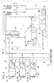
- FIG. 1 shows a refrigerant cycle diagram of a multi-type air conditioner 1 according to this embodiment.
- the multi-type air conditioner 1 includes one outdoor unit 3, a gas pipe 5 and a liquid pipe 7 leading out of the outdoor unit 3, and a plurality of indoor units 9 connected in parallel between the gas pipe 5 and the liquid pipe 7 through branching devices.
- the outdoor unit 3 includes an inverter-driven compressor 13 that compresses refrigerant; an oil separator 15 that separates lubricating oil from refrigerant gas; a four-way control valve 17 that switches the circulation direction of the refrigerant; an outdoor heat exchanger 19 that performs heat exchange between the refrigerant and the outside air; a supercooling coil 21 that is formed integrally with the outdoor heat exchanger 19; an outdoor electric expansion valve for heating (EEVH) 23; a receiver 25 that holds the liquid refrigerant; a supercooling heat exchanger 27 that supercools the liquid refrigerant; a supercooling electric expansion valve (EEVSC) 29 that controls the amount of refrigerant diverted into the supercooling heat exchanger 27; a small-capacity accumulator 31 that separates liquid from the refrigerant gas taken into the compressor 13 and holds the liquid refrigerant; a gas-side operation valve 33; and a liquid-side operation valve 35.
- EVH outdoor electric expansion valve for heating
- these components are connected by refrigerant pipes including a discharge pipe 37A, a gas pipe 37B, a liquid pipe 37C, a gas pipe 37D, an intake pipe 37E, and a branch pipe 37F for supercooling, forming an outdoor-side refrigerant circuit.
- the rotational speed of the compressor 13, i.e., the load and the amount of discharged refrigerant gas, is adjusted by the output frequency of the inverter. The larger the frequency, the larger the load.
- the gas pipe 5 and the liquid pipe 7 are refrigerant pipes that are connected to the gas-side operation valve 33 and the liquid-side operation valve 35 of the outdoor unit 3.
- the lengths of the gas pipe 5 and the liquid pipe 7 are appropriately determined at the time of installation on site, in accordance with the distances between the outdoor unit 3 and the indoor units 9 connected thereto.
- An appropriate number of branching devices 11 are provided at intermediate locations in the gas pipe 5 and the liquid pipe 7, and an appropriate number of indoor units 9 are connected through these branching devices 11.
- the indoor units 9 each include an indoor heat exchanger 39 that performs heat exchange between the refrigerant and the indoor air to condition the indoor air, and an indoor electric expansion valve for cooling (EEVC) 41.
- the indoor electric expansion valve (EEVC) 41 is connected to the liquid pipe 7, and the indoor heat exchanger 39 is connected to the gas pipe 5.
- the multi-type air conditioner 1 includes a control unit 43 that controls the operation thereof.
- the control unit 43 includes an oil-return control section 45 that controls the oil-return operation of the multi-type air conditioner 1, and an input section 47 that adjusts the details of the control performed by the oil-return control section 45.
- the oil-return control section 45 includes timing-determination means that determines the timing at which the oil-return operation is performed on the basis of, for example, the inputted operating conditions of the multi-type air conditioner 1. This, for example, estimates the amounts of lubricating oil discharged from the compressor 13 on the basis of the operating conditions, integrates them, and, when the integrated amount has reached a predetermined amount of oil, determines that an oil-return operation needs to be performed.
- the oil-return control section 45 acquires necessary information from various sensors, switches ports of the four-way control valve 17 using a computer program including a processing procedure of a control method on the basis of the information, and controls the load on the compressor 13, the degrees of opening of the indoor electric expansion valve for cooling (EEVC) 41 and outdoor electric expansion valve for heating (EEVH) 23, etc.
- the input section 47 is, for example, a switch employing a seven-segment display. This switch includes a portion in which information indicating the positional relationship, in the vertical direction, between the outdoor unit 3 and the indoor units 9 is set and a portion in which the distance, in the vertical direction, between the outdoor unit 3 and the indoor unit 9 that is farthest from the outdoor unit 3 in the height direction is set.
- the positional relationship in the vertical direction is set by, for example, selecting an indication meaning "higher” if the outdoor unit 3 is located above the indoor units 9, and selecting an indication meaning "lower” if the outdoor unit 3 is located below the indoor units 9.
- the distance in the vertical direction is set by, for example, selecting a group that matches the installation state from groups divided by an appropriate size, e.g., 1 m or 5 m. Note that they may be input through a remote controller.
- a cooling operation is performed as follows.
- High-temperature, high-pressure refrigerant gas compressed by the compressor 13 is discharged into the discharge pipe 37A.
- This refrigerant gas is circulated toward the gas pipe 37B by the four-way control valve 17, after lubricating oil contained in the refrigerant is separated by the oil separator 15.
- the refrigerant gas passing through the gas pipe 37B undergoes heat exchange with the outside air blown by an outdoor fan in the outdoor heat exchanger 19 and is condensed and liquefied, becoming liquid refrigerant.
- this liquid refrigerant passes through the outdoor electric expansion valve 23 and is temporarily held in the receiver 25, so that the circulated amount is adjusted.
- part of the liquid refrigerant from the receiver 25 is diverted into the branch pipe 37F for supercooling and undergoes heat exchange with the refrigerant having been adiabatically expanded by the supercooling electric expansion valve (EEVSC) 29, so that it is cooled to a predetermined supercooling temperature.
- the liquid refrigerant having been cooled to a predetermined supercooling temperature passes through the liquid-side operation valve 35 and is led out of the outdoor unit 3 into the liquid pipe 7.
- the liquid refrigerant led out into the liquid pipe 7 flows via the branching devices 11 into the indoor electric expansion valve (EEVC) 41 of each indoor unit 9.
- This liquid refrigerant is adiabatically expanded by the indoor electric expansion valve (EEVC) 41 and, in the form of a gas-liquid two phase flow, flows into the indoor heat exchanger 39.
- EEVC indoor electric expansion valve
- the indoor air circulated by an indoor fan undergoes heat exchange with the refrigerant, and the indoor air is cooled to be used to cool the room.
- the refrigerant converted into gas is led out into the gas pipe 5 and is merged with the refrigerant gas from other indoor units 9.
- the refrigerant gas merged at the gas pipe 5 returns again to the outdoor unit 3, passes through the gas-side operation valve 33, the gas pipe 37D, and the four-way control valve 17, and reaches the intake pipe 37E.
- the refrigerant gas is merged with the refrigerant gas from the branch pipe 37F and is introduced into the accumulator 31. Liquid contained in the refrigerant gas is separated in the accumulator 31, and only gas is taken into the compressor 13. This refrigerant is compressed again in the compressor 13.
- the cooling operation is performed by repeating the above-described cycle.
- the oil-return control section 45 starts the oil-return operation.
- the oil-return control section 45 increases the output frequency of the inverter of the compressor 13 to increase the supply amount of the refrigerant without changing the circulation route thereof.
- the lubricating oil remaining in the gas pipe 5 is recovered to the outdoor unit 3 side.
- oil-return control section 45 may increase the degree of opening of the indoor electric expansion valve for cooling (EEVC) 41 compared to that during the cooling operation, so that the liquid refrigerant is mixed with the refrigerant circulating in the multi-type air conditioner 1 and the lubricating oil is recovered with the liquid refrigerant.
- EEVC indoor electric expansion valve for cooling
- a heating operation is performed as follows.
- High-temperature, high-pressure refrigerant gas compressed by the compressor 13 is discharged into the discharge pipe 37A.
- This refrigerant gas is circulated toward the gas pipe 37D by the four-way control valve 17, after lubricating oil contained in the refrigerant is separated by the oil separator 15.
- This refrigerant is led out of the outdoor unit 3 via the gas-side operation valve 33 and the gas pipe 5 and is introduced into the indoor units 9 via the branching devices 11.
- the high-temperature, high-pressure refrigerant gas introduced into the indoor units 9 undergoes heat exchange with the indoor air circulated by the indoor fans in the indoor heat exchangers 39, and the indoor air is heated to be used to heat the room.
- the liquid refrigerant condensed and liquefied by being cooled by the indoor air reaches the branching devices 11 via the indoor electric expansion valves (EEVC) 41 and, after being merged with the refrigerant from other indoor units 9, returns to the outdoor unit 3 through the liquid pipe 7.
- the degree of opening of the indoor electric expansion valves (EEVC) 41 is controlled so that the degree of supercooling of the refrigerant at the outlets of the indoor heat exchangers 39, serving as condensers, is a constant value.
- the liquid refrigerant returned to the outdoor unit 3 passes through the liquid-side operation valve 35 and the liquid pipe 37C, and reaches the supercooling heat exchanger 27, where it is supercooled, similarly to the case of cooling. Thereafter, the liquid refrigerant flows into the receiver 25 and is temporarily held, so that the circulated amount is adjusted.
- This liquid refrigerant flows through the liquid pipe 37C to the outdoor electric expansion valve (EEVH) 23, where it is adiabatically expanded, and then flows into the outdoor heat exchanger 19 via the supercooling coil 21.
- EEVH outdoor electric expansion valve
- the outdoor heat exchanger 19 the outside air blown by the outdoor fan undergoes heat exchange with the refrigerant.
- the refrigerant absorbs heat from the outside air and is vaporized.
- This gas refrigerant flows from the outdoor heat exchanger 19, through the gas pipe 37B, the four-way control valve 17, and the intake pipe 37E, and is merged with the refrigerant gas from the branch pipe 37F for supercooling. Then, it is introduced into the accumulator 31. Liquid contained in the refrigerant gas is separated in the accumulator 31, and only gas is taken into the compressor 13. This refrigerant is compressed again in the compressor 13. The heating operation is performed by repeating the above-described cycle.
- the oil-return control section 45 During the heating operation, if the timing-determination means of the oil-return control section 45 determines that an oil-return operation is necessary, the oil-return control section 45 starts the oil-return operation.
- the oil-return control section 45 switches the four-way control valve 17 to provide the same refrigerant circulation route as the cooling operation and makes the degree of opening of the indoor electric expansion valves for cooling (EEVC) 41 the same as that during the cooling operation. Then, the output frequency of the inverter of the compressor 13 is increased so that the supply amount of the refrigerant is increased. Thus, the lubricating oil remaining in the gas pipe 5 is recovered to the outdoor unit 3 side.
- EEVC indoor electric expansion valves for cooling
- the oil-return control section 45 may increase the degree of opening of the indoor electric expansion valves for cooling (EEVC) 41 compared to that during the cooling operation to mix the liquid refrigerant with the refrigerant circulating in the multi-type air conditioner 1, so that the lubricating oil is recovered with the liquid refrigerant.
- EEVC indoor electric expansion valves for cooling
- the outdoor unit 3 When this multi-type air conditioner 1 is installed in, for example, a building, the outdoor unit 3 may be installed on the roof or in the basement. For example, if the outdoor unit 3 is installed on the roof, the positional relationship between the outdoor unit 3 and the indoor units 9 in the vertical direction is such that the outdoor unit 3 is located at a higher position. In contrast, if the outdoor unit 3 is installed in the basement, the positional relationship between the outdoor unit 3 and the indoor units 9 in the vertical direction is such that the outdoor unit 3 is located at a lower position.
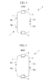
- FIGS. 2 and 3 show the flows of refrigerant (arrows with solid lines in FIGS. 2 and 3 ) during the heating operation ( FIG. 2 ) and during the cooling operation ( FIG. 3 ) in the case where the outdoor unit 3 is located at a higher position, and also show the flows of refrigerant (arrows with two-dot chain lines in FIGS. 2 and 3 ) during the respective oil-return operations.
- FIGS. 4 and 5 show the flows of refrigerant (arrows with the solid line in FIGS. 4 and 5 ) during the heating operation ( FIG. 4 ) and during the cooling operation ( FIG. 5 ) in the case where the outdoor unit 3 is located at a lower position, and also show the flows of refrigerant (arrows with two-dot chain lines in FIGS. 4 and 5 ) during the respective oil-return operations.
- the oil-return operation by means of the oil-return control is not performed during, for example, either cooling or heating. Therefore, undesirable deterioration of the air-conditioning feeling, the occurrence of noise, and the loss of motive power can be reduced.
- the moving speed of the refrigerant needs to be equal to or higher than a predetermined speed, for example, 8 m/s, to move the lubricating oil. If the amount of refrigerant discharged from the compressor 13 is constant, the moving speed of the refrigerant varies depending on the distance between the outdoor unit 3 and the indoor units 9 in the vertical direction, i.e., the head magnitude. Therefore, head with which a predetermined speed can be maintained, or guaranteed, is set. This head is, for example, 50 m.
- the head which is the distance between the outdoor unit 3 and the indoor units 9 in the vertical direction, is equal to or less than 50 m.
- the load on the compressor 13 is set the same as that in the case where the head is 50 m, the moving speed of the refrigerant exceeds 8 m/s. In other words, if the moving speed of the refrigerant is maintained at 8 m/s, the load on the compressor can be reduced.
- the head between the outdoor unit 3 and the indoor unit 9 that is farthest therefrom in the vertical direction is inputted through the input means 47.
- the oil-return control section 45 reduces the load on the compressor 13 when performing the oil-return operation, in accordance with the proportion of the actual distance between the outdoor unit 3 and the indoor units 9 in the vertical direction, i.e., the head H, to the assumed distance between the outdoor unit 3 and the indoor units 9 in the vertical direction (50 m).
- the load on the compressor 13 during the oil-return operation can be reduced, the motive power required during the oil-return operation can be reduced.
- the oil-return operation is performed simultaneously with the cooling operation, if the time required for the next oil-return operation is reduced by the corresponding time or if that state lasts for a long time, the next oil-return operation can be omitted altogether (canceled).
- the load on the compressor 13 is reduced or the frequency of the oil-return operation is reduced in accordance with the inputted head, undesirable deterioration of the air-conditioning feeling, the occurrence of noise, and the loss of motive power can be reduced.
- the position of the outdoor unit 3 in the vertical direction and the head be inputted at the installation site of the multi-type air conditioner 1, so that the input is assuredly performed.
- FIG. 6 shows a refrigerant cycle diagram of a cooling/heating free multi-type air conditioner 51 according to this embodiment.
- the multi-type air conditioner 51 includes one outdoor unit 53, a plurality of indoor units 55, a high-pressure gas pipe 57, a low-pressure gas pipe 59, and a liquid pipe 61 that connect them to each other.
- the outdoor unit 53 includes an inverter-driven compressor 63 that compresses refrigerant; an oil separator 65 that separates lubricating oil from refrigerant gas; an outdoor-side four-way valve 67 that switches the circulation direction of the refrigerant; an outdoor heat exchanger 69 that performs heat exchange between the refrigerant and the outside air; an outdoor electric expansion valve for heating (EEVH) 71; a receiver 73 that holds the liquid refrigerant; a supercooling heat exchanger 75 that supercools the liquid refrigerant; a supercooling electric expansion valve (EEVSC) 77 that controls the amount of refrigerant diverted into the supercooling heat exchanger 75; an accumulator 79 that separates liquid from the refrigerant gas taken into the compressor 63 and holds the liquid refrigerant; a low-pressure gas-side operation valve 81; a high-pressure gas-side operation valve 83; and a liquid-side operation valve 85.
- EVH outdoor electric expansion valve for heating
- a plurality, for example, two compressors 63 are provided.
- scroll compressors are used for these compressors 63.
- these two compressors 63 may be simultaneously operated, or only one of them may be operated while the other one serves as a backup.
- the refrigerant compressed in the compressors 63 is discharged, in the form of high-pressure gas refrigerant, into the high-pressure gas pipe 57.
- a plurality, for example, two outdoor-side four-way valves 67 are provided.
- Each of the outdoor-side four-way valves 67 is connected at one port to the high-pressure gas pipe 57 located in the outdoor unit 53, at another port to the outdoor heat exchanger 69, at another port to the low-pressure gas pipe 59 through the low-pressure gas branching pipe 87, and at another port to the low-pressure gas branching pipe 87 through a strainer and a capillary tube.
- the outdoor heat exchangers 69 and the outdoor electric expansion valves for heating (EEVH) 71 a plurality of each, for example, two are provided.
- the low-pressure gas pipe 59 located in the outdoor unit 53 is connected to each of the compressors 63 via the accumulator 79.
- a plurality of indoor units 55 are provided, and they have the same structure.
- the indoor units 55 each have an indoor heat exchanger 89 that performs heat exchange with the indoor air.
- An expansion valve 93 is provided on a liquid-refrigerant branching pipe 91 connecting the indoor heat exchanger 89 and the liquid pipe 9.
- Each of the indoor units 55 has a diversion controller 95 that switches between the high-pressure gas pipe 57 and the low-pressure gas pipe 59.
- the diversion controller 95 has an indoor-side four-way valve 97 that switches between the connection of the high-pressure gas pipe 57 and the indoor heat exchanger 89 and the connection of the low-pressure gas pipe 59 and the indoor heat exchanger 89, and a high/low-pressure bypass pipe 99 that connects the high-pressure gas pipe 57 and the low-pressure gas pipe 59.
- FIG. 6 shows three indoor units 55. These are, in order from above, examples of pipe connection in the heating operation, pipe connection in the cooling operation, and pipe connection in the oil-return operation.
- this multi-type air conditioner 51 includes a control unit 101 that controls the operation thereof.
- the control unit 101 includes an oil-return control unit 103 that has substantially the same structure as that of the first embodiment and controls the oil-return operation of the multi-type air conditioner 51, and has an input unit 105 that adjusts the details of the control performed by the oil-return control unit 103.
- This multi-type air conditioner 51 The cooling/heating operations of this multi-type air conditioner 51 are performed as follows. High-temperature, high-pressure refrigerant gas compressed by the compressors 63 is discharged into the high-pressure gas pipe 57 and is sent toward the indoor units 55. Part of the high-temperature, high-pressure refrigerant gas discharged into the high-pressure gas pipe 57 is branched off, passes through the outdoor-side four-way valves 67, and is condensed and liquefied by undergoing heat exchange with the outside air in the outdoor heat exchanger 69, becoming liquid refrigerant. This liquid refrigerant passes through the outdoor electric expansion valve 71 and is temporarily held in the receiver 73, where the circulated amount is adjusted.
- the liquid refrigerant from the receiver 73 in a process of passing through the supercooling heat exchanger 75, undergoes heat exchange with the refrigerant having been adiabatically expanded by the supercooling electric expansion valve (EEVSC) 77, so that it is cooled to a predetermined supercooling temperature.
- the liquid refrigerant cooled to a predetermined supercooling temperature is led out from the outdoor unit 53, via the liquid-side operation valve 85, into the liquid pipe 61.
- the indoor-side four-way valve 97 is operated to connect the high-pressure gas pipe 57 and the indoor heat exchanger 89, so that the high-temperature, high-pressure gas refrigerant is introduced from the high-pressure gas pipe 57 into the indoor heat exchanger 89.
- the high-temperature, high-pressure refrigerant gas introduced therein undergoes heat exchange with the indoor air in the indoor heat exchanger 89.
- the indoor air is heated to be used to heat the room.
- the liquid refrigerant condensed and liquefied by being cooled by the indoor air flows in the liquid pipe 61 via the indoor electric expansion valves (EEVC) 93.
- EEVC indoor electric expansion valves
- the indoor-side four-way valve 97 is operated to connect the low-pressure gas pipe 59 and the indoor heat exchanger 89.
- the liquid refrigerant flowing from the liquid pipe 61 is adiabatically expanded by the indoor electric expansion valve (EEVC) 93 and flows, in the form of a gas-liquid two phase flow, in the indoor heat exchanger 89.
- the indoor heat exchanger 89 performs heat exchange between the indoor air and the refrigerant, and the indoor air is cooled to be used to cool the room.
- the refrigerant converted to gas is led out into the low-pressure gas pipe 59 and is returned to the outdoor unit 53.
- the high/low-pressure bypass pipe 99 is opened to allow the high-pressure gas pipe 57 and the low-pressure gas pipe 59 to communicate with each other.
- the high-pressure gas flowing in the diversion controller 95 passes through the high/low-pressure bypass pipe 99 from the high-pressure gas pipe 57 to the low-pressure gas pipe 59.
- This gas refrigerant allows the lubricating oil to be recovered by the outdoor unit 53.
- this multi-type air conditioner 51 When this multi-type air conditioner 51 is installed in, for example, a building, depending on the installation site of the outdoor unit 3, the positional relationship between the outdoor unit 53 and the indoor units 55 in the vertical direction is such that the outdoor unit 53 may be located at a higher position or may be located at a lower position.
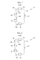
- FIGS. 7 and 8 show the flows of refrigerant (arrows with solid lines in FIGS. 7 and 8 ) during the heating operation ( FIG. 7 ) and during the cooling operation ( FIG. 8 ) when the outdoor unit 53 is located at a higher position, and also show the flows of refrigerant (arrows with two-dot chain lines in FIGS. 7 and 8 ) during the respective oil-return operations.
- FIGS. 9 and 10 show the flows of refrigerant (arrows with the solid line in FIGS. 9 and 10 ) during the heating operation ( FIG. 9 ) and during the cooling operation ( FIG. 10 ) when the outdoor unit 53 is located at a lower position, and also show the flows of refrigerant (arrows with two-dot chain lines in FIGS. 9 and 10 ) during the respective oil-return operations.
- high-pressure gas refrigerant KG1 from the outdoor unit 53 passes downward through the high-pressure gas pipe 57 and is sent to the indoor units 55.
- This high-pressure gas refrigerant KG1 is converted into high-pressure liquid refrigerant KL1 in the indoor units 55, passes upward through the liquid pipe 61, and is sent to the outdoor unit 53.
- low-pressure gas refrigerant TG1 from the indoor units 55 passes downward through the low-pressure gas pipe 59 and is sent to the outdoor unit 53.
- This low-pressure gas refrigerant TG1 is converted into high-pressure liquid refrigerant KL1 in the outdoor unit 53, passes upward through the liquid pipe 61, and is sent to the indoor units 55.
- whether the outdoor unit 53 is located at a higher position or at a lower position is inputted through input means 105. Based on this input, the oil-return control unit 103 does not perform the oil-return operation during the heating operation in the case where the outdoor unit 53 is located at a higher position and during the cooling operation in the case where the outdoor unit 53 is located at a lower position.
- the oil-return operation by means of the oil-return control is not performed during, for example, either cooling or heating. Therefore, undesirable deterioration of the air-conditioning feeling, the occurrence of noise, and the loss of motive power can be reduced.
- the low-pressure gas refrigerant TG1 is sent from the indoor units 55 through the low-pressure gas pipe 59 upward to the outdoor unit 53.
- the lubricating oil remains in the low-pressure gas pipe 59 during the cooling operation.
- the high-pressure gas refrigerant KG1 is sent from the outdoor unit 53 through the high-pressure gas pipe 57 upward to the indoor units 55.
- the lubricating oil remains in the high-pressure gas pipe 57 during the cooling operation. Accordingly, in these cases, the oil-return operation needs to be performed.
- the moving speed of the refrigerant needs to be equal to or higher than a predetermined speed, for example, 8 m/s in the low-pressure gas pipe 59, and 6.5 m/s in the high-pressure gas pipe 57, to move the lubricating oil.
- a predetermined speed for example, 8 m/s in the low-pressure gas pipe 59, and 6.5 m/s in the high-pressure gas pipe 57.
- the head which is the distance between the outdoor unit 53 and the indoor units 55 in the vertical direction, is equal to or less than 50 m or 40 m.
- the load on the compressors 63 is set the same as that in the case where the head is maximum, the moving speed of the refrigerant exceeds 8 m/s in the low-pressure gas pipe 59, and exceeds 6.5 m/s in the high-pressure gas pipe 57. In other words, if the moving speed of the refrigerant is maintained at a predetermined value, the load on the compressors 63 can be reduced.
- the head between the outdoor unit 53 and the indoor unit 55 that is farthest therefrom in the vertical direction is inputted through the input means 105.
- the oil-return control unit 103 reduces the load on the compressors 63 when performing the oil-return operation, in accordance with the proportion of the actual distance between the outdoor unit 53 and the indoor units 55 in the vertical direction, i.e., the head H, to the assumed maximum head between the outdoor unit 53 and the indoor units 55.
- the load on the compressors 63 during the oil-return operation can be reduced, the motive power required during the oil-return operation can be reduced.
- the oil-return operation is performed simultaneously with the cooling operation, if the time required for the next oil-return operation is reduced by the corresponding time or if that state lasts for a long time, the next oil-return operation can be omitted altogether (canceled).
- the load on the compressors 63 is reduced or the frequency of the oil-return operation is reduced in accordance with the inputted head, undesirable deterioration of the air-conditioning feeling, the occurrence of noise, and the loss of motive power can be reduced.
- the position of the outdoor unit in the vertical direction and the head be inputted at the installation site of the multi-type air conditioner 51, so that the input is assuredly performed.
Landscapes
- Engineering & Computer Science (AREA)
- Physics & Mathematics (AREA)
- Mechanical Engineering (AREA)
- Thermal Sciences (AREA)
- General Engineering & Computer Science (AREA)
- Air Conditioning Control Device (AREA)
- Compression-Type Refrigeration Machines With Reversible Cycles (AREA)
Abstract
Description
- The present invention relates to an oil-return operation method for a multi-type air conditioner and to a multi-type air conditioner that performs an oil-return operation using the same.
- A multi-type air conditioner is formed of one outdoor unit and a plurality of indoor units connected thereto in parallel with one another. Multi-type air conditioners include so-called cooling/heating free air conditioners in which each indoor unit can freely perform cooling or heating (see Patent Citation 1) and cooling/heating switching air conditioners in which all the indoor units perform cooling or heating together (see Patent Citation 2).
Because these multi-type air conditioners are used in, for example, buildings having multiple rooms (installation sites of the indoor units), the distance between the outdoor unit and the indoor units is large, and the distance in the height direction is also large. - Compressors of air conditioners, including the multi-type air conditioners, use lubricating oil for lubricating sliding parts thereof. This lubricating oil is made of an oil that is soluble in refrigerant, and part of which flows, together with the refrigerant discharged from the compressor, in a system including indoor heat exchangers and an outdoor heat exchanger and is recovered again by the compressor.
This lubricating oil inhibits heat transfer if deposited on the inner walls of the heat exchangers while flowing in the system. Furthermore, deposition of the lubricating oil on the inner wall of a refrigerant pipe reduces the amount of the lubricating oil returning to the compressor, resulting in insufficient lubrication of the compressor.
In order to recover the lubricating oil deposited and remaining on the inner walls of the heat exchangers and refrigerant pipe, an oil-return operation is performed to recover the lubricating oil at the compressor. - This oil-return operation need not be performed on a portion through which liquid refrigerant flows because the oil is recovered with the liquid refrigerant, but is performed on a portion through which gas refrigerant flows.
Accordingly, during cooling, the oil-return operation is performed by, for example, increasing the rotational speed of the compressor to increase the flow rate of the gas refrigerant in the system or allowing the refrigerant, in the liquid state, to flow out of the indoor heat exchangers and to flow through a gas pipe (liquid back). During heating, the oil-return operation is performed by, for example, temporarily switching to a cooling cycle and performing a pseudo-defrosting operation. - Patent Citation 1:
- Japanese Unexamined Patent Application, Publication No.
2006-125762 - Japanese Unexamined Patent Application, Publication No.
Sho 63-73052 - Meanwhile, the details of the oil-return operation of the multi-type air conditioner are defined assuming the worst-case installation conditions of the indoor units and outdoor unit, e.g., the distance between the outdoor unit and the indoor units (pipe length) and the distance in the height direction (head), so that sufficient oil return can be performed under such conditions.
On the other hand, multi-type air conditioners are installed in various types of buildings. For example, the outdoor unit of the multi-type air conditioner may be installed on the roof, in the basement, or somewhere between them. Moreover, the distance, in the vertical direction, between the outdoor unit and the indoor unit that is farthest therefrom (head) also varies. These conditions are usually less unfavorable than the assumed installation conditions of the multi-type air conditioner. - Therefore, an excessive oil-return operation is performed under normal installation conditions of the multi-type air conditioner. This may cause deterioration of the air-conditioning feeling, such as undesired stopping of cooling/heating, a fault such as the occurrence of unwanted noise, and the loss of motive power.
- The present invention has been made in view of the above-described circumstances, and an object thereof is to provide an oil-return operation method for a multi-type air conditioner with which an oil-return operation according to the installation conditions can be performed and undesirable deterioration of the air-conditioning feeling, the occurrence of noise, and the loss of motive power can be reduced, and to provide a multi-type air conditioner using the same.
- To overcome the above-described problems, the present invention employs the following solutions.
That is, a first aspect of the present invention is an oil-return operation method for a multi-type air conditioner having at least one outdoor unit and a plurality of indoor units connected thereto in parallel with one another. The positional relationship, in the vertical direction, between the outdoor unit and the indoor units is inputted, and oil-return control the details of which are in accordance with the inputted positional relationship in the vertical direction is performed. - The oil-return operation method for a multi-type air conditioner according to this aspect has, as one parameter for the oil-return control, the positional relationship between the outdoor unit and the indoor units in the vertical direction. By inputting the positional relationship, in the vertical direction, between the outdoor unit and the indoor units of the multi-type air conditioner to be installed, oil-return control the details of which are in accordance with the positional relationship in the vertical direction is performed.
For example, in a multi-type air conditioner that switches between cooling and heating, the gas refrigerant moves from the indoor units to the outdoor unit during cooling, and from the outdoor unit to the indoor units during heating, and the liquid refrigerant moves from the outdoor unit to the indoor units during cooling, and from the indoor units to the outdoor unit during heating.
On the other hand, the lubricating oil does not remain in the liquid refrigerant part. Even in the gas refrigerant portion, if it moves from above to below, it does not remain but moves due to the effect of gravity. - Accordingly, if the outdoor unit is located higher than the indoor units, during heating, the gas refrigerant moves downward to the indoor units and, from there, is returned, in the form of liquid refrigerant, to the outdoor unit. Thus, the lubricating oil does not remain but is recovered by the outdoor unit. Moreover, if the outdoor unit is located lower than the indoor units, during cooling, the liquid refrigerant moves upward to the indoor units and, from there, is returned, in the form of gas refrigerant, to the lower outdoor unit. Thus, the lubricating oil does not remain but is recovered by the outdoor unit.
Thus, if the outdoor unit is located higher than the indoor units, the oil-return operation is not performed during heating, and, if the outdoor unit is located lower than the indoor units, the oil-return operation is not performed during cooling. - As has been described, based on the inputted positional relationship, in the vertical direction, between the outdoor unit and the indoor units, the oil-return operation by means of the oil-return control is not performed during, for example, either cooling or heating. Therefore, undesirable deterioration of the air-conditioning feeling, the occurrence of noise, and the loss of motive power can be reduced.
- A second aspect of the present invention is an oil-return operation method for a multi-type air conditioner having at least one outdoor unit and a plurality of indoor units connected thereto in parallel with one another. The distance, in the vertical direction, between the outdoor unit and the indoor unit that is farthest from the outdoor unit in the height direction is inputted, and oil-return control the details of which are in accordance with the inputted distance in the vertical direction is performed.
- For example, the assumed rate of the gas refrigerant necessary to convey the lubricating oil is defined. This rate is defined on the basis of the amount of refrigerant discharged from the compressor per unit time and the capacity of the pipe, in other words, the distance between the outdoor unit and the indoor units. Assuming the worst-case distance between the indoor units and the outdoor unit (pipe length), distance in the height direction (head), etc., the load on the compressor is defined such that the rate of the gas refrigerant necessary for this distance can be obtained.
- The oil-return operation method for a multi-type air conditioner according to this aspect has, as one parameter for the oil-return control, the distance, in the vertical direction, between the outdoor unit and the indoor units (head). By inputting the distance, in the vertical direction, between the outdoor unit and the indoor units of the multi-type air conditioner to be installed, oil-return control the details of which are in accordance with the distance in the vertical direction is performed.
More specifically, the load on the compressor during the oil-return operation is reduced in accordance with the proportion of the inputted distance, in the vertical direction, between the outdoor unit and the indoor units to the assumed distance, in the vertical direction, between the outdoor unit and the indoor units. In other words, the load on the compressor is defined such that it satisfies the assumed rate of the gas refrigerant necessary to convey the lubricating oil over the inputted distance, in the vertical direction, between the outdoor unit and the indoor units.
As has been described, because, for example, the load on the compressor is reduced in accordance with the inputted distance, in the vertical direction, between the outdoor unit and the indoor unit, the motive power required for the oil-return operation can be reduced. - If the load on the compressor during the oil-return operation is set low, for example, an increase in the load on the compressor to satisfy the required cooling capacity during the cooling operation, in which the operation is performed in the same direction, results in a situation where the load on the compressor during the oil-return operation is exceeded.
That is, because the oil-return operation is performed simultaneously with the cooling operation, the time required for the next oil-return operation can be reduced by the corresponding time, or, if this state lasts for a long time, the next oil-return operation can be omitted altogether (canceled).
As has been described, because, for example, the load on the compressor is reduced in accordance with the inputted distance, in the vertical direction, between the outdoor unit and the indoor unit, undesirable deterioration of the air-conditioning feeling, the occurrence of noise, and the loss of motive power can be reduced. - A third aspect of the present invention is an oil-return operation method for a multi-type air conditioner having at least one outdoor unit and a plurality of indoor units connected thereto in parallel with one another. The positional relationship, in the vertical direction, between the outdoor unit and the indoor units and the distance, in the vertical direction, between the outdoor unit and the indoor unit that is farthest from the outdoor unit in the height direction is inputted, and oil-return control the details of which are in accordance with the inputted positional relationship in the vertical direction and the distance in the height direction is performed.
- The oil-return operation method for a multi-type air conditioner according to this aspect has, as parameters for the oil-return control, the positional relationship, in the vertical direction, between the outdoor unit and the indoor units and the distance, in the vertical direction, between the outdoor unit and the indoor units. By inputting the positional relationship, in the vertical direction, between the outdoor unit and the indoor units of the multi-type air conditioner to be installed and the distance, in the vertical direction, between the outdoor unit and the indoor unit, oil-return control the details of which are in accordance with the positional relationship in the vertical direction is performed.
Each of these parameters has the above-described effects and advantages.
Moreover, depending on the positional relationship in the vertical direction, if the traveling direction of the gas refrigerant during the oil-return operation is from above to below, for example, the load on the compressor can be further reduced with the assistance of gravity. - In the above-described aspects, it is preferable that the positional relationship, in the vertical direction, between the outdoor unit and the indoor units and/or the distance, in the vertical direction, between the outdoor unit and the indoor unit that is farthest from the outdoor unit in the height direction be inputted at an installation site.
This makes it possible to set the positional relationship, in the vertical direction, between the outdoor unit and the indoor units and/or the distance, in the vertical direction, between the outdoor unit and the indoor unit that is farthest from the outdoor unit in the height direction in the state in which they are actually installed. Thus, setting can be assuredly performed. - A fourth aspect of the present invention is a multi-type air conditioner that performs an oil-return operation using any one of the above-described oil-return operation methods for a multi-type air conditioner.
- In the multi-type air conditioner according to this aspect, because the oil-return operation method allowing for the oil-return operation according to the installation conditions is used, undesirable deterioration of the air-conditioning feeling, the occurrence of noise, and the loss of motive power can be reduced.
- According to the present invention, the positional relationship, in the vertical direction, between the outdoor unit and the indoor units and/or the distance, in the vertical direction, between the outdoor unit and the indoor units are inputted, and oil-return control the details of which are in accordance with the inputted positional relationship in the vertical direction and/or the distance between the outdoor unit and the indoor units in the vertical direction is performed. Thus, undesirable deterioration of the air-conditioning feeling, the occurrence of noise, and the loss of motive power can be reduced.
-
- [
FIG. 1] FIG. 1 is a diagram showing a refrigeration cycle of a multi-type air conditioner according to a first embodiment of the present invention. - [
FIG. 2] FIG. 2 is a schematic view showing the flow of refrigerant during a heating operation and the flow of refrigerant during an oil-return operation in the multi-type air conditioner according to the first embodiment of the present invention. - [
FIG. 3] FIG. 3 is a schematic view showing the flow of refrigerant during a cooling operation and the flow of refrigerant during the oil-return operation in the multi-type air conditioner according to the first embodiment of the present invention. - [
FIG. 4] FIG. 4 is a schematic view showing the flow of refrigerant during the heating operation and the flow of refrigerant during the oil-return operation in the multi-type air conditioner according to the first embodiment of the present invention. - [
FIG. 5] FIG. 5 is a schematic view showing the flow of refrigerant during the cooling operation and the flow of refrigerant during the oil-return operation in the multi-type air conditioner according to the first embodiment of the present invention. - [
FIG. 6] FIG. 6 is a diagram showing a refrigeration cycle of a multi-type air conditioner according to a second embodiment of the present invention. - [
FIG. 7] FIG. 7 is a schematic view showing the flow of refrigerant during the heating operation and the flow of refrigerant during the oil-return operation in the multi-type air conditioner according to the second embodiment of the present invention. - [
FIG. 8] FIG. 8 is a schematic view showing the flow of refrigerant during the cooling operation and the flow of refrigerant during the oil-return operation in the multi-type air conditioner according to the second embodiment of the present invention. - [
FIG. 9] FIG. 9 is a schematic view showing the flow of refrigerant during the heating operation and the flow of refrigerant during the oil-return operation in the multi-type air conditioner according to the second embodiment of the present invention. - [
FIG. 10] FIG. 10 is a schematic view showing the flow of refrigerant during the cooling operation and the flow of refrigerant during the oil-return operation in the multi-type air conditioner according to the second embodiment of the present invention. -
- 1:
- multi-type air conditioner
- 3:
- outdoor unit
- 9:
- indoor unit
- 45:
- oil-return control unit
- 47:
- input means
- 51:
- multi-type air conditioner
- 53:
- outdoor unit
- 55:
- indoor unit
- 103:
- oil-return control unit
- 105:
- input means
- A first embodiment of the present invention will be described below with reference to
FIGS. 1 to 5 . -
FIG. 1 shows a refrigerant cycle diagram of a multi-type air conditioner 1 according to this embodiment. - The multi-type air conditioner 1 includes one
outdoor unit 3, agas pipe 5 and aliquid pipe 7 leading out of theoutdoor unit 3, and a plurality ofindoor units 9 connected in parallel between thegas pipe 5 and theliquid pipe 7 through branching devices. - The
outdoor unit 3 includes an inverter-drivencompressor 13 that compresses refrigerant; anoil separator 15 that separates lubricating oil from refrigerant gas; a four-way control valve 17 that switches the circulation direction of the refrigerant; anoutdoor heat exchanger 19 that performs heat exchange between the refrigerant and the outside air; a supercoolingcoil 21 that is formed integrally with theoutdoor heat exchanger 19; an outdoor electric expansion valve for heating (EEVH) 23; areceiver 25 that holds the liquid refrigerant; asupercooling heat exchanger 27 that supercools the liquid refrigerant; a supercooling electric expansion valve (EEVSC) 29 that controls the amount of refrigerant diverted into thesupercooling heat exchanger 27; a small-capacity accumulator 31 that separates liquid from the refrigerant gas taken into thecompressor 13 and holds the liquid refrigerant; a gas-side operation valve 33; and a liquid-side operation valve 35. - As is known, these components are connected by refrigerant pipes including a
discharge pipe 37A, agas pipe 37B, aliquid pipe 37C, agas pipe 37D, anintake pipe 37E, and abranch pipe 37F for supercooling, forming an outdoor-side refrigerant circuit.
The rotational speed of thecompressor 13, i.e., the load and the amount of discharged refrigerant gas, is adjusted by the output frequency of the inverter. The larger the frequency, the larger the load. - The
gas pipe 5 and theliquid pipe 7 are refrigerant pipes that are connected to the gas-side operation valve 33 and the liquid-side operation valve 35 of theoutdoor unit 3.
The lengths of thegas pipe 5 and theliquid pipe 7 are appropriately determined at the time of installation on site, in accordance with the distances between theoutdoor unit 3 and theindoor units 9 connected thereto.
An appropriate number of branchingdevices 11 are provided at intermediate locations in thegas pipe 5 and theliquid pipe 7, and an appropriate number ofindoor units 9 are connected through these branchingdevices 11. - The
indoor units 9 each include anindoor heat exchanger 39 that performs heat exchange between the refrigerant and the indoor air to condition the indoor air, and an indoor electric expansion valve for cooling (EEVC) 41.
The indoor electric expansion valve (EEVC) 41 is connected to theliquid pipe 7, and theindoor heat exchanger 39 is connected to thegas pipe 5. - The multi-type air conditioner 1 includes a
control unit 43 that controls the operation thereof. Thecontrol unit 43 includes an oil-return control section 45 that controls the oil-return operation of the multi-type air conditioner 1, and aninput section 47 that adjusts the details of the control performed by the oil-return control section 45.
The oil-return control section 45 includes timing-determination means that determines the timing at which the oil-return operation is performed on the basis of, for example, the inputted operating conditions of the multi-type air conditioner 1. This, for example, estimates the amounts of lubricating oil discharged from thecompressor 13 on the basis of the operating conditions, integrates them, and, when the integrated amount has reached a predetermined amount of oil, determines that an oil-return operation needs to be performed. - The oil-
return control section 45 acquires necessary information from various sensors, switches ports of the four-way control valve 17 using a computer program including a processing procedure of a control method on the basis of the information, and controls the load on thecompressor 13, the degrees of opening of the indoor electric expansion valve for cooling (EEVC) 41 and outdoor electric expansion valve for heating (EEVH) 23, etc.
Theinput section 47 is, for example, a switch employing a seven-segment display. This switch includes a portion in which information indicating the positional relationship, in the vertical direction, between theoutdoor unit 3 and theindoor units 9 is set and a portion in which the distance, in the vertical direction, between theoutdoor unit 3 and theindoor unit 9 that is farthest from theoutdoor unit 3 in the height direction is set. The positional relationship in the vertical direction is set by, for example, selecting an indication meaning "higher" if theoutdoor unit 3 is located above theindoor units 9, and selecting an indication meaning "lower" if theoutdoor unit 3 is located below theindoor units 9. The distance in the vertical direction is set by, for example, selecting a group that matches the installation state from groups divided by an appropriate size, e.g., 1 m or 5 m.
Note that they may be input through a remote controller. - In the above-described multi-type air conditioner 1, a cooling operation is performed as follows.
High-temperature, high-pressure refrigerant gas compressed by thecompressor 13 is discharged into thedischarge pipe 37A. This refrigerant gas is circulated toward thegas pipe 37B by the four-way control valve 17, after lubricating oil contained in the refrigerant is separated by theoil separator 15.
The refrigerant gas passing through thegas pipe 37B undergoes heat exchange with the outside air blown by an outdoor fan in theoutdoor heat exchanger 19 and is condensed and liquefied, becoming liquid refrigerant.
After being cooled by the supercoolingcoil 21, this liquid refrigerant passes through the outdoorelectric expansion valve 23 and is temporarily held in thereceiver 25, so that the circulated amount is adjusted. - In a process of passing through the supercooling
heat exchanger 27 through theliquid pipe 37C, part of the liquid refrigerant from thereceiver 25 is diverted into thebranch pipe 37F for supercooling and undergoes heat exchange with the refrigerant having been adiabatically expanded by the supercooling electric expansion valve (EEVSC) 29, so that it is cooled to a predetermined supercooling temperature.
The liquid refrigerant having been cooled to a predetermined supercooling temperature passes through the liquid-side operation valve 35 and is led out of theoutdoor unit 3 into theliquid pipe 7. The liquid refrigerant led out into theliquid pipe 7 flows via the branchingdevices 11 into the indoor electric expansion valve (EEVC) 41 of eachindoor unit 9. - This liquid refrigerant is adiabatically expanded by the indoor electric expansion valve (EEVC) 41 and, in the form of a gas-liquid two phase flow, flows into the
indoor heat exchanger 39.
In theindoor heat exchanger 39, the indoor air circulated by an indoor fan undergoes heat exchange with the refrigerant, and the indoor air is cooled to be used to cool the room.
On the other hand, the refrigerant converted into gas is led out into thegas pipe 5 and is merged with the refrigerant gas from otherindoor units 9. - The refrigerant gas merged at the
gas pipe 5 returns again to theoutdoor unit 3, passes through the gas-side operation valve 33, thegas pipe 37D, and the four-way control valve 17, and reaches theintake pipe 37E. The refrigerant gas is merged with the refrigerant gas from thebranch pipe 37F and is introduced into theaccumulator 31.
Liquid contained in the refrigerant gas is separated in theaccumulator 31, and only gas is taken into thecompressor 13. This refrigerant is compressed again in thecompressor 13.
The cooling operation is performed by repeating the above-described cycle. - During the cooling operation, if the timing-determination means of the oil-
return control section 45 determines that an oil-return operation is necessary, the oil-return control section 45 starts the oil-return operation. The oil-return control section 45 increases the output frequency of the inverter of thecompressor 13 to increase the supply amount of the refrigerant without changing the circulation route thereof. Thus, the lubricating oil remaining in thegas pipe 5 is recovered to theoutdoor unit 3 side. Thus, during the cooling operation and the oil-return operation, the directions of flow of the gas refrigerant in thegas pipe 5 are the same.
Note that the oil-return control section 45 may increase the degree of opening of the indoor electric expansion valve for cooling (EEVC) 41 compared to that during the cooling operation, so that the liquid refrigerant is mixed with the refrigerant circulating in the multi-type air conditioner 1 and the lubricating oil is recovered with the liquid refrigerant. - On the other hand, a heating operation is performed as follows.
High-temperature, high-pressure refrigerant gas compressed by thecompressor 13 is discharged into thedischarge pipe 37A. This refrigerant gas is circulated toward thegas pipe 37D by the four-way control valve 17, after lubricating oil contained in the refrigerant is separated by theoil separator 15.
This refrigerant is led out of theoutdoor unit 3 via the gas-side operation valve 33 and thegas pipe 5 and is introduced into theindoor units 9 via the branchingdevices 11.
The high-temperature, high-pressure refrigerant gas introduced into theindoor units 9 undergoes heat exchange with the indoor air circulated by the indoor fans in theindoor heat exchangers 39, and the indoor air is heated to be used to heat the room. - On the other hand, the liquid refrigerant condensed and liquefied by being cooled by the indoor air reaches the branching
devices 11 via the indoor electric expansion valves (EEVC) 41 and, after being merged with the refrigerant from otherindoor units 9, returns to theoutdoor unit 3 through theliquid pipe 7.
Note that, during heating, in theindoor units 9, the degree of opening of the indoor electric expansion valves (EEVC) 41 is controlled so that the degree of supercooling of the refrigerant at the outlets of theindoor heat exchangers 39, serving as condensers, is a constant value. - The liquid refrigerant returned to the
outdoor unit 3 passes through the liquid-side operation valve 35 and theliquid pipe 37C, and reaches thesupercooling heat exchanger 27, where it is supercooled, similarly to the case of cooling. Thereafter, the liquid refrigerant flows into thereceiver 25 and is temporarily held, so that the circulated amount is adjusted.
This liquid refrigerant flows through theliquid pipe 37C to the outdoor electric expansion valve (EEVH) 23, where it is adiabatically expanded, and then flows into theoutdoor heat exchanger 19 via the supercoolingcoil 21.
In theoutdoor heat exchanger 19, the outside air blown by the outdoor fan undergoes heat exchange with the refrigerant. The refrigerant absorbs heat from the outside air and is vaporized. - This gas refrigerant flows from the
outdoor heat exchanger 19, through thegas pipe 37B, the four-way control valve 17, and theintake pipe 37E, and is merged with the refrigerant gas from thebranch pipe 37F for supercooling. Then, it is introduced into theaccumulator 31.
Liquid contained in the refrigerant gas is separated in theaccumulator 31, and only gas is taken into thecompressor 13. This refrigerant is compressed again in thecompressor 13.
The heating operation is performed by repeating the above-described cycle. - During the heating operation, if the timing-determination means of the oil-
return control section 45 determines that an oil-return operation is necessary, the oil-return control section 45 starts the oil-return operation. The oil-return control section 45 switches the four-way control valve 17 to provide the same refrigerant circulation route as the cooling operation and makes the degree of opening of the indoor electric expansion valves for cooling (EEVC) 41 the same as that during the cooling operation. Then, the output frequency of the inverter of thecompressor 13 is increased so that the supply amount of the refrigerant is increased. Thus, the lubricating oil remaining in thegas pipe 5 is recovered to theoutdoor unit 3 side. As has been described, during the heating operation and the oil-return operation, the directions of flow of the gas refrigerant in thegas pipe 5 are opposite.
Note that the oil-return control section 45 may increase the degree of opening of the indoor electric expansion valves for cooling (EEVC) 41 compared to that during the cooling operation to mix the liquid refrigerant with the refrigerant circulating in the multi-type air conditioner 1, so that the lubricating oil is recovered with the liquid refrigerant. - Next, an oil-return operation according to this embodiment will be described.
When this multi-type air conditioner 1 is installed in, for example, a building, theoutdoor unit 3 may be installed on the roof or in the basement. For example, if theoutdoor unit 3 is installed on the roof, the positional relationship between theoutdoor unit 3 and theindoor units 9 in the vertical direction is such that theoutdoor unit 3 is located at a higher position. In contrast, if theoutdoor unit 3 is installed in the basement, the positional relationship between theoutdoor unit 3 and theindoor units 9 in the vertical direction is such that theoutdoor unit 3 is located at a lower position. -
FIGS. 2 and 3 show the flows of refrigerant (arrows with solid lines inFIGS. 2 and 3 ) during the heating operation (FIG. 2 ) and during the cooling operation (FIG. 3 ) in the case where theoutdoor unit 3 is located at a higher position, and also show the flows of refrigerant (arrows with two-dot chain lines inFIGS. 2 and 3 ) during the respective oil-return operations.
FIGS. 4 and 5 show the flows of refrigerant (arrows with the solid line inFIGS. 4 and 5 ) during the heating operation (FIG. 4 ) and during the cooling operation (FIG. 5 ) in the case where theoutdoor unit 3 is located at a lower position, and also show the flows of refrigerant (arrows with two-dot chain lines inFIGS. 4 and 5 ) during the respective oil-return operations. - During the heating operation in the case where the
outdoor unit 3 is located at a higher position, as shown inFIG. 2 , high-pressure gas refrigerant KG1 from theoutdoor unit 3 passes downward through thegas pipe 5 and is sent to theindoor units 9. This high-pressure gas refrigerant KG1 is converted into high-pressure liquid refrigerant KL1 in theindoor units 9, passes upward through theliquid pipe 7, and is sent to theoutdoor unit 3.
During the cooling operation in the case where theoutdoor unit 3 is located at a lower position, as shown inFIG. 5 , low-pressure gas refrigerant TG1 from theindoor units 9 passes downward through thegas pipe 5 and is sent to theoutdoor unit 3. This low-pressure gas refrigerant TG1 is converted into high-pressure liquid refrigerant KL1 in theoutdoor unit 3, passes upward through theliquid pipe 7, and is sent to theindoor units 9. - As has been described, during the heating operation in the case where the
outdoor unit 3 is located at a higher position and during the cooling operation in the case where theoutdoor unit 3 is located at a lower position, because the gas refrigerant moves through thegas pipe 5 from above to below, and also because downward gravity acts on the lubricating oil, the lubricating oil does not remain in thegas pipe 5 but moves to theindoor units 9 or theoutdoor unit 3.
Accordingly, because the lubricating oil does not remain in thegas pipe 5, the oil-return operation is unnecessary.
In this embodiment, whether theoutdoor unit 3 is located at a higher position or at a lower position is inputted through input means 47. Based on this input, the oil-return control section 45 does not perform the oil-return operation during the heating operation in the case where theoutdoor unit 3 is located at a higher position and during the cooling operation in the case where theoutdoor unit 3 is located at a lower position. - As has been described, based on the inputted positional relationship between the
outdoor unit 3 and theindoor units 9 in the vertical direction, the oil-return operation by means of the oil-return control is not performed during, for example, either cooling or heating. Therefore, undesirable deterioration of the air-conditioning feeling, the occurrence of noise, and the loss of motive power can be reduced. - On the other hand, as shown in
FIG. 3 , during the cooling operation in the case where theoutdoor unit 3 is located at a higher position, the low-pressure gas refrigerant TG1 is sent from theindoor units 9 through thegas pipe 5 upward to theoutdoor unit 3. Thus, the lubricating oil remains in thegas pipe 5 during the cooling operation.
Moreover, as shown inFIG. 4 , during the heating operation in the case where theoutdoor unit 3 is located at a lower position, the high-pressure gas refrigerant KG1 is sent from theoutdoor unit 3 through thegas pipe 5 upward to theindoor units 9. Thus, the lubricating oil remains in thegas pipe 5 during the cooling operation.
Accordingly, in these cases, the oil-return operation needs to be performed. - In this oil-return operation, the moving speed of the refrigerant needs to be equal to or higher than a predetermined speed, for example, 8 m/s, to move the lubricating oil.
If the amount of refrigerant discharged from thecompressor 13 is constant, the moving speed of the refrigerant varies depending on the distance between theoutdoor unit 3 and theindoor units 9 in the vertical direction, i.e., the head magnitude. Therefore, head with which a predetermined speed can be maintained, or guaranteed, is set. This head is, for example, 50 m. - When the multi-type air conditioner 1 is installed, the head, which is the distance between the
outdoor unit 3 and theindoor units 9 in the vertical direction, is equal to or less than 50 m. At this time, if the load on thecompressor 13 is set the same as that in the case where the head is 50 m, the moving speed of the refrigerant exceeds 8 m/s. In other words, if the moving speed of the refrigerant is maintained at 8 m/s, the load on the compressor can be reduced.
In this embodiment, the head between theoutdoor unit 3 and theindoor unit 9 that is farthest therefrom in the vertical direction is inputted through the input means 47. - Based on this input, the oil-
return control section 45 reduces the load on thecompressor 13 when performing the oil-return operation, in accordance with the proportion of the actual distance between theoutdoor unit 3 and theindoor units 9 in the vertical direction, i.e., the head H, to the assumed distance between theoutdoor unit 3 and theindoor units 9 in the vertical direction (50 m).
Thus, because the load on thecompressor 13 during the oil-return operation can be reduced, the motive power required during the oil-return operation can be reduced. - Moreover, when the load on the
compressor 13 during the oil-return operation is set low, a situation where, for example, the load on thecompressor 13 needed to satisfy the cooling capacity required during the cooling operation, shown inFIGS. 3 and5 , exceeds the load on thecompressor 13 during the oil-return operation occurs. At this time, because the direction of flow of the refrigerant is the same as that during the oil-return operation, the lubricating oil can be recovered, similarly to the case of the oil-return operation. - Accordingly, because the oil-return operation is performed simultaneously with the cooling operation, if the time required for the next oil-return operation is reduced by the corresponding time or if that state lasts for a long time, the next oil-return operation can be omitted altogether (canceled).
As has been described, because, for example, the load on thecompressor 13 is reduced or the frequency of the oil-return operation is reduced in accordance with the inputted head, undesirable deterioration of the air-conditioning feeling, the occurrence of noise, and the loss of motive power can be reduced. - In this case, it is preferable that the position of the
outdoor unit 3 in the vertical direction and the head be inputted at the installation site of the multi-type air conditioner 1, so that the input is assuredly performed. - Next, a second embodiment of the present invention will be described with reference to
FIGS. 6 to 10 .
FIG. 6 shows a refrigerant cycle diagram of a cooling/heating freemulti-type air conditioner 51 according to this embodiment.
Themulti-type air conditioner 51 includes oneoutdoor unit 53, a plurality ofindoor units 55, a high-pressure gas pipe 57, a low-pressure gas pipe 59, and aliquid pipe 61 that connect them to each other. - The
outdoor unit 53 includes an inverter-drivencompressor 63 that compresses refrigerant; anoil separator 65 that separates lubricating oil from refrigerant gas; an outdoor-side four-way valve 67 that switches the circulation direction of the refrigerant; anoutdoor heat exchanger 69 that performs heat exchange between the refrigerant and the outside air; an outdoor electric expansion valve for heating (EEVH) 71; areceiver 73 that holds the liquid refrigerant; a supercooling heat exchanger 75 that supercools the liquid refrigerant; a supercooling electric expansion valve (EEVSC) 77 that controls the amount of refrigerant diverted into the supercooling heat exchanger 75; anaccumulator 79 that separates liquid from the refrigerant gas taken into thecompressor 63 and holds the liquid refrigerant; a low-pressure gas-side operation valve 81; a high-pressure gas-side operation valve 83; and a liquid-side operation valve 85. - A plurality, for example, two
compressors 63 are provided. Preferably, scroll compressors are used for thesecompressors 63. Depending on the required air-conditioning capacity, these twocompressors 63 may be simultaneously operated, or only one of them may be operated while the other one serves as a backup.
The refrigerant compressed in thecompressors 63 is discharged, in the form of high-pressure gas refrigerant, into the high-pressure gas pipe 57. - A plurality, for example, two outdoor-side four-
way valves 67 are provided. Each of the outdoor-side four-way valves 67 is connected at one port to the high-pressure gas pipe 57 located in theoutdoor unit 53, at another port to theoutdoor heat exchanger 69, at another port to the low-pressure gas pipe 59 through the low-pressuregas branching pipe 87, and at another port to the low-pressuregas branching pipe 87 through a strainer and a capillary tube. - As for the
outdoor heat exchangers 69 and the outdoor electric expansion valves for heating (EEVH) 71, a plurality of each, for example, two are provided.
The low-pressure gas pipe 59 located in theoutdoor unit 53 is connected to each of thecompressors 63 via theaccumulator 79. - A plurality of
indoor units 55 are provided, and they have the same structure.
Theindoor units 55 each have anindoor heat exchanger 89 that performs heat exchange with the indoor air. Anexpansion valve 93 is provided on a liquid-refrigerant branching pipe 91 connecting theindoor heat exchanger 89 and theliquid pipe 9.
Each of theindoor units 55 has adiversion controller 95 that switches between the high-pressure gas pipe 57 and the low-pressure gas pipe 59. - The
diversion controller 95 has an indoor-side four-way valve 97 that switches between the connection of the high-pressure gas pipe 57 and theindoor heat exchanger 89 and the connection of the low-pressure gas pipe 59 and theindoor heat exchanger 89, and a high/low-pressure bypass pipe 99 that connects the high-pressure gas pipe 57 and the low-pressure gas pipe 59.
FIG. 6 shows threeindoor units 55. These are, in order from above, examples of pipe connection in the heating operation, pipe connection in the cooling operation, and pipe connection in the oil-return operation. - Similarly to the first embodiment, this
multi-type air conditioner 51 includes acontrol unit 101 that controls the operation thereof. Thecontrol unit 101 includes an oil-return control unit 103 that has substantially the same structure as that of the first embodiment and controls the oil-return operation of themulti-type air conditioner 51, and has aninput unit 105 that adjusts the details of the control performed by the oil-return control unit 103. - The cooling/heating operations of this
multi-type air conditioner 51 are performed as follows.
High-temperature, high-pressure refrigerant gas compressed by thecompressors 63 is discharged into the high-pressure gas pipe 57 and is sent toward theindoor units 55.
Part of the high-temperature, high-pressure refrigerant gas discharged into the high-pressure gas pipe 57 is branched off, passes through the outdoor-side four-way valves 67, and is condensed and liquefied by undergoing heat exchange with the outside air in theoutdoor heat exchanger 69, becoming liquid refrigerant.
This liquid refrigerant passes through the outdoorelectric expansion valve 71 and is temporarily held in thereceiver 73, where the circulated amount is adjusted. - The liquid refrigerant from the
receiver 73, in a process of passing through the supercooling heat exchanger 75, undergoes heat exchange with the refrigerant having been adiabatically expanded by the supercooling electric expansion valve (EEVSC) 77, so that it is cooled to a predetermined supercooling temperature.
The liquid refrigerant cooled to a predetermined supercooling temperature is led out from theoutdoor unit 53, via the liquid-side operation valve 85, into theliquid pipe 61. - In the
indoor units 55 that perform the heating operation, the indoor-side four-way valve 97 is operated to connect the high-pressure gas pipe 57 and theindoor heat exchanger 89, so that the high-temperature, high-pressure gas refrigerant is introduced from the high-pressure gas pipe 57 into theindoor heat exchanger 89.
The high-temperature, high-pressure refrigerant gas introduced therein undergoes heat exchange with the indoor air in theindoor heat exchanger 89. Thus, the indoor air is heated to be used to heat the room.
On the other hand, the liquid refrigerant condensed and liquefied by being cooled by the indoor air flows in theliquid pipe 61 via the indoor electric expansion valves (EEVC) 93. - On the other hand, in the
indoor units 55 that perform the cooling operation, the indoor-side four-way valve 97 is operated to connect the low-pressure gas pipe 59 and theindoor heat exchanger 89.
The liquid refrigerant flowing from theliquid pipe 61 is adiabatically expanded by the indoor electric expansion valve (EEVC) 93 and flows, in the form of a gas-liquid two phase flow, in theindoor heat exchanger 89.
Theindoor heat exchanger 89 performs heat exchange between the indoor air and the refrigerant, and the indoor air is cooled to be used to cool the room.
On the other hand, the refrigerant converted to gas is led out into the low-pressure gas pipe 59 and is returned to theoutdoor unit 53. - Next, the oil-return operation will be described.
The high/low-pressure bypass pipe 99 is opened to allow the high-pressure gas pipe 57 and the low-pressure gas pipe 59 to communicate with each other. The high-pressure gas flowing in thediversion controller 95 passes through the high/low-pressure bypass pipe 99 from the high-pressure gas pipe 57 to the low-pressure gas pipe 59. This gas refrigerant allows the lubricating oil to be recovered by theoutdoor unit 53. - When this
multi-type air conditioner 51 is installed in, for example, a building, depending on the installation site of theoutdoor unit 3, the positional relationship between theoutdoor unit 53 and theindoor units 55 in the vertical direction is such that theoutdoor unit 53 may be located at a higher position or may be located at a lower position. -
FIGS. 7 and 8 show the flows of refrigerant (arrows with solid lines inFIGS. 7 and 8 ) during the heating operation (FIG. 7 ) and during the cooling operation (FIG. 8 ) when theoutdoor unit 53 is located at a higher position, and also show the flows of refrigerant (arrows with two-dot chain lines inFIGS. 7 and 8 ) during the respective oil-return operations.
FIGS. 9 and 10 show the flows of refrigerant (arrows with the solid line inFIGS. 9 and 10 ) during the heating operation (FIG. 9 ) and during the cooling operation (FIG. 10 ) when theoutdoor unit 53 is located at a lower position, and also show the flows of refrigerant (arrows with two-dot chain lines inFIGS. 9 and 10 ) during the respective oil-return operations. - During the heating operation in the case where the
outdoor unit 53 is located at a higher position, as shown inFIG. 7 , high-pressure gas refrigerant KG1 from theoutdoor unit 53 passes downward through the high-pressure gas pipe 57 and is sent to theindoor units 55. This high-pressure gas refrigerant KG1 is converted into high-pressure liquid refrigerant KL1 in theindoor units 55, passes upward through theliquid pipe 61, and is sent to theoutdoor unit 53.
During the cooling operation in the case where theoutdoor unit 53 is located at a lower position, as shown inFIG. 10 , low-pressure gas refrigerant TG1 from theindoor units 55 passes downward through the low-pressure gas pipe 59 and is sent to theoutdoor unit 53. This low-pressure gas refrigerant TG1 is converted into high-pressure liquid refrigerant KL1 in theoutdoor unit 53, passes upward through theliquid pipe 61, and is sent to theindoor units 55. - As has been described, during the heating operation in the case where the
outdoor unit 53 is located at a higher position and during the cooling operation in the case where theoutdoor unit 53 is located at a lower position, because the gas refrigerant moves through the high-pressure gas pipe 57 or the low-pressure gas pipe 59 from above to below, and also because downward gravity acts on the lubricating oil, the lubricating oil does not remain in the high-pressure gas pipe 57 or the low-pressure gas pipe 59 but moves to theindoor units 55 or theoutdoor unit 53.
Accordingly, because the lubricating oil does not remain in the high-pressure gas pipe 57 or the low-pressure gas pipe 59, the oil-return operation is unnecessary.
In this embodiment, whether theoutdoor unit 53 is located at a higher position or at a lower position is inputted through input means 105. Based on this input, the oil-return control unit 103 does not perform the oil-return operation during the heating operation in the case where theoutdoor unit 53 is located at a higher position and during the cooling operation in the case where theoutdoor unit 53 is located at a lower position. - As has been described, based on the inputted positional relationship between the
outdoor unit 53 and theindoor units 55 in the vertical direction, the oil-return operation by means of the oil-return control is not performed during, for example, either cooling or heating. Therefore, undesirable deterioration of the air-conditioning feeling, the occurrence of noise, and the loss of motive power can be reduced. - On the other hand, as shown in
FIG. 8 , during the cooling operation in the case where theoutdoor unit 53 is located at a higher position, the low-pressure gas refrigerant TG1 is sent from theindoor units 55 through the low-pressure gas pipe 59 upward to theoutdoor unit 53. Thus, the lubricating oil remains in the low-pressure gas pipe 59 during the cooling operation.
Moreover, as shown inFIG. 9 , during the heating operation in the case where theoutdoor unit 53 is located at a lower position, the high-pressure gas refrigerant KG1 is sent from theoutdoor unit 53 through the high-pressure gas pipe 57 upward to theindoor units 55. Thus, the lubricating oil remains in the high-pressure gas pipe 57 during the cooling operation.
Accordingly, in these cases, the oil-return operation needs to be performed. - In this oil-return operation, the moving speed of the refrigerant needs to be equal to or higher than a predetermined speed, for example, 8 m/s in the low-
pressure gas pipe 59, and 6.5 m/s in the high-pressure gas pipe 57, to move the lubricating oil.
If the amount of refrigerant discharged from thecompressor 63 is constant, the moving speed of the refrigerant varies depending on the distance between theoutdoor unit 53 and theindoor units 55 in the vertical direction, i.e., the head magnitude. Therefore, head with which a predetermined speed can be maintained, or guaranteed, is set. This head is, for example, 50 m in the low-pressure pipe 59 in the case where theoutdoor unit 53 is located at a higher position, and 40 m in the high-pressure pipe 57 in the case where theoutdoor unit 53 is located at a lower position. - When the
multi-type air conditioner 51 is installed, the head, which is the distance between theoutdoor unit 53 and theindoor units 55 in the vertical direction, is equal to or less than 50 m or 40 m. At this time, if the load on thecompressors 63 is set the same as that in the case where the head is maximum, the moving speed of the refrigerant exceeds 8 m/s in the low-pressure gas pipe 59, and exceeds 6.5 m/s in the high-pressure gas pipe 57. In other words, if the moving speed of the refrigerant is maintained at a predetermined value, the load on thecompressors 63 can be reduced.
In this embodiment, the head between theoutdoor unit 53 and theindoor unit 55 that is farthest therefrom in the vertical direction is inputted through the input means 105. - Based on this input, the oil-
return control unit 103 reduces the load on thecompressors 63 when performing the oil-return operation, in accordance with the proportion of the actual distance between theoutdoor unit 53 and theindoor units 55 in the vertical direction, i.e., the head H, to the assumed maximum head between theoutdoor unit 53 and theindoor units 55.
Thus, because the load on thecompressors 63 during the oil-return operation can be reduced, the motive power required during the oil-return operation can be reduced. - Moreover, when the load on the
compressors 63 during the oil-return operation is set low, a situation where, for example, the load on thecompressors 63 needed to satisfy the cooling capacity required during the cooling operation, shown inFIGS. 8 and10 , exceeds the load on thecompressors 63 during the oil-return operation occurs. At this time, because the direction of flow of the refrigerant is the same as that during the oil-return operation, the lubricating oil can be recovered similarly to the case of the oil-return operation. - Accordingly, because the oil-return operation is performed simultaneously with the cooling operation, if the time required for the next oil-return operation is reduced by the corresponding time or if that state lasts for a long time, the next oil-return operation can be omitted altogether (canceled).
As has been described, because, for example, the load on thecompressors 63 is reduced or the frequency of the oil-return operation is reduced in accordance with the inputted head, undesirable deterioration of the air-conditioning feeling, the occurrence of noise, and the loss of motive power can be reduced. - In this case, it is preferable that the position of the outdoor unit in the vertical direction and the head be inputted at the installation site of the
multi-type air conditioner 51, so that the input is assuredly performed. - Note that the present invention is not limited to the invention according to the above-described embodiments, but may be appropriately modified so long as it does not depart from the spirit thereof.
Furthermore, specific numerals, such as time and temperature, shown as examples in the above-described embodiments are merely examples, and the present invention is of course not limited thereto.
Claims (5)
- An oil-return operation method for a multi-type air conditioner having at least one outdoor unit and a plurality of indoor units connected thereto in parallel with one another,
wherein the positional relationship, in the vertical direction, between the outdoor unit and the indoor units is inputted, and
wherein oil-return control the details of which are in accordance with the inputted positional relationship in the vertical direction is performed. - An oil-return operation method for a multi-type air conditioner having at least one outdoor unit and a plurality of indoor units connected thereto in parallel with one another,
wherein the distance, in the vertical direction, between the outdoor unit and the indoor unit that is farthest from the outdoor unit in the height direction is inputted, and
wherein oil-return control the details of which are in accordance with the inputted distance in the vertical direction is performed. - An oil-return operation method for a multi-type air conditioner having at least one outdoor unit and a plurality of indoor units connected thereto in parallel with one another,
wherein the positional relationship, in the vertical direction, between the outdoor unit and the indoor units and the distance, in the vertical direction, between the outdoor unit and the indoor unit that is farthest from the outdoor unit in the height direction is inputted, and
wherein oil-return control the details of which are in accordance with the inputted positional relationship in the vertical direction and the distance in the height direction is performed. - The oil-return operation method for a multi-type air conditioner according to any one of claims 1 to 3,
wherein the positional relationship, in the vertical direction, between the outdoor unit and the indoor units and/or the distance, in the vertical direction, between the outdoor unit and the indoor unit that is farthest from the outdoor unit in the height direction is inputted at an installation site. - A multi-type air conditioner that performs an oil-return operation using the oil-return operation method for a multi-type air conditioner according to any one of claims 1 to 4.
Applications Claiming Priority (2)
| Application Number | Priority Date | Filing Date | Title |
|---|---|---|---|
| JP2008088594A JP5398159B2 (en) | 2008-03-28 | 2008-03-28 | Oil return operation method for multi-type air conditioner and multi-type air conditioner |
| PCT/JP2009/050440 WO2009119134A1 (en) | 2008-03-28 | 2009-01-15 | Oil return operation method for multi-type air conditioner and multi-type air conditioner |
Publications (2)
| Publication Number | Publication Date |
|---|---|
| EP2256435A1 true EP2256435A1 (en) | 2010-12-01 |
| EP2256435A4 EP2256435A4 (en) | 2014-05-14 |
Family
ID=41113344
Family Applications (1)
| Application Number | Title | Priority Date | Filing Date |
|---|---|---|---|
| EP09725239.9A Withdrawn EP2256435A4 (en) | 2008-03-28 | 2009-01-15 | MULTI-TYPE AIR CONDITIONER AND METHOD FOR OPERATING OIL RETURN |
Country Status (3)
| Country | Link |
|---|---|
| EP (1) | EP2256435A4 (en) |
| JP (1) | JP5398159B2 (en) |
| WO (1) | WO2009119134A1 (en) |
Cited By (8)
| Publication number | Priority date | Publication date | Assignee | Title |
|---|---|---|---|---|
| EP2375192A3 (en) * | 2010-02-25 | 2014-01-29 | Mitsubishi Heavy Industries, Ltd. | Air-conditioning apparatus |
| CN105157294A (en) * | 2015-10-14 | 2015-12-16 | 珠海格力电器股份有限公司 | Control method and system for intelligent oil return of multi-split air conditioner and multi-split air conditioner system |
| US20160123635A1 (en) * | 2013-05-27 | 2016-05-05 | Gree Electric Appliances, Inc. Of Zhuhai | Oil Return Method for Multi-Split Air Conditioner in Heating |
| EP3252396A4 (en) * | 2015-01-30 | 2018-09-19 | Daikin Industries, Ltd. | Air conditioning device |
| EP3370014A4 (en) * | 2016-02-08 | 2018-12-05 | Mitsubishi Heavy Industries Thermal Systems, Ltd. | Refrigeration cycle device |
| EP3748266A4 (en) * | 2018-02-02 | 2021-01-20 | Qingdao Haier Air-Conditioning Electronic Co., Ltd | VRV OIL RETURN CONTROL PROCESS AND SYSTEM |
| EP3882533A4 (en) * | 2018-11-16 | 2022-01-05 | Qingdao Haier Air-Conditioning Electronic Co., Ltd | PROCESS AND CONTROL SYSTEM FOR REFRIGERATION, OIL RETURN AND NOISE REDUCTION OF A MULTI-SPLIT AIR CONDITIONER |
| CN117321360A (en) * | 2021-05-27 | 2023-12-29 | 三菱电机株式会社 | Refrigerant leakage determination device, control device, refrigerant leakage determination program and refrigerant leakage determination method |
Families Citing this family (10)
| Publication number | Priority date | Publication date | Assignee | Title |
|---|---|---|---|---|
| JP6540666B2 (en) * | 2016-11-24 | 2019-07-10 | ダイキン工業株式会社 | Refrigeration system |
| CN111656106B (en) * | 2018-01-17 | 2021-09-07 | 东芝开利株式会社 | Control method of air conditioner and air conditioner |
| AU2020448974B2 (en) * | 2020-05-20 | 2023-12-14 | Mitsubishi Electric Corporation | Refrigeration and air-conditioning apparatus |
| CN111878892B (en) * | 2020-06-29 | 2022-02-22 | 宁波奥克斯电气股份有限公司 | Oil return method and device of multi-split air conditioner system, air conditioner and storage medium |
| WO2022004895A1 (en) * | 2020-07-03 | 2022-01-06 | ダイキン工業株式会社 | Use as refrigerant in compressor, compressor, and refrigeration cycle apparatus |
| CN114110986B (en) * | 2020-08-26 | 2023-01-24 | 广东美的制冷设备有限公司 | Oil return control method for multi-split air conditioning system, air conditioner and storage medium |
| CN113108419B (en) * | 2021-03-15 | 2022-06-17 | 珠海格力电器股份有限公司 | Control method of multi-split air conditioning system |
| CN113028682B (en) * | 2021-03-30 | 2022-03-29 | 宁波奥克斯电气股份有限公司 | Oil return control method and air conditioner |
| CN114484718B (en) * | 2022-01-14 | 2023-11-07 | 宁波奥克斯电气股份有限公司 | Air conditioner oil return control method and device and air conditioner |
| CN115950067B (en) * | 2022-12-05 | 2024-08-30 | 珠海格力电器股份有限公司 | Air conditioning system, oil return control method and device thereof and storage medium |
Family Cites Families (6)
| Publication number | Priority date | Publication date | Assignee | Title |
|---|---|---|---|---|
| JPS6373052A (en) | 1986-09-13 | 1988-04-02 | ダイキン工業株式会社 | Oil recovery operation controller for refrigerator |
| US6125648A (en) * | 1997-10-10 | 2000-10-03 | Hill; Herbert L. | Multi-riser refrigeration system with oil return means |
| JP2002349938A (en) * | 2001-05-22 | 2002-12-04 | Mitsubishi Heavy Ind Ltd | Refrigeration apparatus and oil return control method thereof |
| JP2003214715A (en) * | 2002-01-28 | 2003-07-30 | Daikin Ind Ltd | Oil recovery method for refrigeration equipment |
| JP3885601B2 (en) * | 2002-02-08 | 2007-02-21 | ダイキン工業株式会社 | Refrigerant and oil recovery method, refrigerant and oil recovery control device, and air conditioner |
| JP2006125762A (en) | 2004-10-29 | 2006-05-18 | Mitsubishi Heavy Ind Ltd | Indoor unit, air conditioning device comprising the same, and its operating method |
-
2008
- 2008-03-28 JP JP2008088594A patent/JP5398159B2/en not_active Expired - Fee Related
-
2009
- 2009-01-15 WO PCT/JP2009/050440 patent/WO2009119134A1/en not_active Ceased
- 2009-01-15 EP EP09725239.9A patent/EP2256435A4/en not_active Withdrawn
Cited By (13)
| Publication number | Priority date | Publication date | Assignee | Title |
|---|---|---|---|---|
| EP2375192A3 (en) * | 2010-02-25 | 2014-01-29 | Mitsubishi Heavy Industries, Ltd. | Air-conditioning apparatus |
| US10094599B2 (en) * | 2013-05-27 | 2018-10-09 | Gree Electric Appliances, Inc. Of Zhuhai | Oil return method for multi-split air conditioning in heating |
| US20160123635A1 (en) * | 2013-05-27 | 2016-05-05 | Gree Electric Appliances, Inc. Of Zhuhai | Oil Return Method for Multi-Split Air Conditioner in Heating |
| EP3006845A4 (en) * | 2013-05-27 | 2017-03-01 | Gree Electric Appliances, Inc. of Zhuhai | Oil return method for multiple air conditioning unit in heating |
| AU2013391135B2 (en) * | 2013-05-27 | 2017-12-14 | Gree Electric Appliances, Inc. Of Zhuhai | Oil return method for multiple air conditioning unit in heating |
| AU2013391135C1 (en) * | 2013-05-27 | 2018-04-05 | Gree Electric Appliances, Inc. Of Zhuhai | Oil return method for multiple air conditioning unit in heating |
| EP3252396A4 (en) * | 2015-01-30 | 2018-09-19 | Daikin Industries, Ltd. | Air conditioning device |
| US10184683B2 (en) | 2015-01-30 | 2019-01-22 | Daikin Industries, Ltd. | Air conditioning device |
| CN105157294A (en) * | 2015-10-14 | 2015-12-16 | 珠海格力电器股份有限公司 | Control method and system for intelligent oil return of multi-split air conditioner and multi-split air conditioner system |
| EP3370014A4 (en) * | 2016-02-08 | 2018-12-05 | Mitsubishi Heavy Industries Thermal Systems, Ltd. | Refrigeration cycle device |
| EP3748266A4 (en) * | 2018-02-02 | 2021-01-20 | Qingdao Haier Air-Conditioning Electronic Co., Ltd | VRV OIL RETURN CONTROL PROCESS AND SYSTEM |
| EP3882533A4 (en) * | 2018-11-16 | 2022-01-05 | Qingdao Haier Air-Conditioning Electronic Co., Ltd | PROCESS AND CONTROL SYSTEM FOR REFRIGERATION, OIL RETURN AND NOISE REDUCTION OF A MULTI-SPLIT AIR CONDITIONER |
| CN117321360A (en) * | 2021-05-27 | 2023-12-29 | 三菱电机株式会社 | Refrigerant leakage determination device, control device, refrigerant leakage determination program and refrigerant leakage determination method |
Also Published As
| Publication number | Publication date |
|---|---|
| JP2009243719A (en) | 2009-10-22 |
| EP2256435A4 (en) | 2014-05-14 |
| WO2009119134A1 (en) | 2009-10-01 |
| JP5398159B2 (en) | 2014-01-29 |
Similar Documents
| Publication | Publication Date | Title |
|---|---|---|
| JP5398159B2 (en) | Oil return operation method for multi-type air conditioner and multi-type air conditioner | |
| EP1995536B1 (en) | Air conditioner | |
| EP2557377B1 (en) | Air conditioning and hot-water supply composite system | |
| US10088206B2 (en) | Air-conditioning apparatus | |
| EP2196748B1 (en) | Refrigeration apparatus and method for controlling the same | |
| EP2236960B1 (en) | Air conditioner and method of determining amount of refrigerant | |
| EP2196746B1 (en) | Refrigeration apparatus | |
| EP2163839A1 (en) | Air conditioner | |
| EP1522802A1 (en) | Refrigeration equipment | |
| JP6448775B2 (en) | Air conditioner | |
| JP2011149659A (en) | Air conditioner | |
| JPWO2013099047A1 (en) | Air conditioner | |
| EP3358276A2 (en) | Air conditioning system | |
| JPWO2003078903A1 (en) | Pressure adjusting device for air conditioner and air conditioner having the same | |
| WO2004013549A1 (en) | Refrigeration equipment | |
| JP2014102053A (en) | Multi-type air conditioning system | |
| JP5186398B2 (en) | Air conditioner | |
| JPWO2004013550A1 (en) | Refrigeration equipment | |
| JP2925715B2 (en) | Refrigeration equipment | |
| JP2011127775A (en) | Air conditioner | |
| JP3883725B2 (en) | Method of operating air conditioner and air conditioner | |
| CN116829885B (en) | Refrigeration cycle device | |
| CN222086142U (en) | Air conditioning system | |
| EP4679002A1 (en) | Outdoor unit of air conditioning device, and air conditioning device | |
| JP2011214795A (en) | Multi-type air conditioner |
Legal Events
| Date | Code | Title | Description |
|---|---|---|---|
| PUAI | Public reference made under article 153(3) epc to a published international application that has entered the european phase |
Free format text: ORIGINAL CODE: 0009012 |
|
| 17P | Request for examination filed |
Effective date: 20100325 |
|
| AK | Designated contracting states |
Kind code of ref document: A1 Designated state(s): AT BE BG CH CY CZ DE DK EE ES FI FR GB GR HR HU IE IS IT LI LT LU LV MC MK MT NL NO PL PT RO SE SI SK TR |
|
| AX | Request for extension of the european patent |
Extension state: AL BA RS |
|
| DAX | Request for extension of the european patent (deleted) | ||
| A4 | Supplementary search report drawn up and despatched |
Effective date: 20140416 |
|
| RIC1 | Information provided on ipc code assigned before grant |
Ipc: F25B 1/00 20060101AFI20140410BHEP Ipc: F24F 11/02 20060101ALI20140410BHEP |
|
| STAA | Information on the status of an ep patent application or granted ep patent |
Free format text: STATUS: EXAMINATION IS IN PROGRESS |
|
| 17Q | First examination report despatched |
Effective date: 20170620 |
|
| RAP1 | Party data changed (applicant data changed or rights of an application transferred) |
Owner name: MITSUBISHI HEAVY INDUSTRIES THERMAL SYSTEMS, LTD. |
|
| RIC1 | Information provided on ipc code assigned before grant |
Ipc: F25B 31/00 20060101AFI20190731BHEP |
|
| GRAP | Despatch of communication of intention to grant a patent |
Free format text: ORIGINAL CODE: EPIDOSNIGR1 |
|
| STAA | Information on the status of an ep patent application or granted ep patent |
Free format text: STATUS: GRANT OF PATENT IS INTENDED |
|
| INTG | Intention to grant announced |
Effective date: 20190924 |
|
| STAA | Information on the status of an ep patent application or granted ep patent |
Free format text: STATUS: THE APPLICATION IS DEEMED TO BE WITHDRAWN |
|
| 18D | Application deemed to be withdrawn |
Effective date: 20200205 |