EP2256327A1 - Noise reducing device, and jet propulsion system - Google Patents
Noise reducing device, and jet propulsion system Download PDFInfo
- Publication number
- EP2256327A1 EP2256327A1 EP09715023A EP09715023A EP2256327A1 EP 2256327 A1 EP2256327 A1 EP 2256327A1 EP 09715023 A EP09715023 A EP 09715023A EP 09715023 A EP09715023 A EP 09715023A EP 2256327 A1 EP2256327 A1 EP 2256327A1
- Authority
- EP
- European Patent Office
- Prior art keywords
- casing
- partition wall
- pylon
- stream
- cylindrical partition
- Prior art date
- Legal status (The legal status is an assumption and is not a legal conclusion. Google has not performed a legal analysis and makes no representation as to the accuracy of the status listed.)
- Granted
Links
Images



Classifications
-
- F—MECHANICAL ENGINEERING; LIGHTING; HEATING; WEAPONS; BLASTING
- F02—COMBUSTION ENGINES; HOT-GAS OR COMBUSTION-PRODUCT ENGINE PLANTS
- F02K—JET-PROPULSION PLANTS
- F02K3/00—Plants including a gas turbine driving a compressor or a ducted fan
- F02K3/02—Plants including a gas turbine driving a compressor or a ducted fan in which part of the working fluid by-passes the turbine and combustion chamber
- F02K3/04—Plants including a gas turbine driving a compressor or a ducted fan in which part of the working fluid by-passes the turbine and combustion chamber the plant including ducted fans, i.e. fans with high volume, low pressure outputs, for augmenting the jet thrust, e.g. of double-flow type
- F02K3/06—Plants including a gas turbine driving a compressor or a ducted fan in which part of the working fluid by-passes the turbine and combustion chamber the plant including ducted fans, i.e. fans with high volume, low pressure outputs, for augmenting the jet thrust, e.g. of double-flow type with front fan
-
- B—PERFORMING OPERATIONS; TRANSPORTING
- B64—AIRCRAFT; AVIATION; COSMONAUTICS
- B64C—AEROPLANES; HELICOPTERS
- B64C7/00—Structures or fairings not otherwise provided for
- B64C7/02—Nacelles
-
- B—PERFORMING OPERATIONS; TRANSPORTING
- B64—AIRCRAFT; AVIATION; COSMONAUTICS
- B64D—EQUIPMENT FOR FITTING IN OR TO AIRCRAFT; FLIGHT SUITS; PARACHUTES; ARRANGEMENT OR MOUNTING OF POWER PLANTS OR PROPULSION TRANSMISSIONS IN AIRCRAFT
- B64D27/00—Arrangement or mounting of power plants in aircraft; Aircraft characterised by the type or position of power plants
- B64D27/02—Aircraft characterised by the type or position of power plants
- B64D27/16—Aircraft characterised by the type or position of power plants of jet type
- B64D27/18—Aircraft characterised by the type or position of power plants of jet type within, or attached to, wings
-
- F—MECHANICAL ENGINEERING; LIGHTING; HEATING; WEAPONS; BLASTING
- F02—COMBUSTION ENGINES; HOT-GAS OR COMBUSTION-PRODUCT ENGINE PLANTS
- F02K—JET-PROPULSION PLANTS
- F02K1/00—Plants characterised by the form or arrangement of the jet pipe or nozzle; Jet pipes or nozzles peculiar thereto
- F02K1/28—Plants characterised by the form or arrangement of the jet pipe or nozzle; Jet pipes or nozzles peculiar thereto using fluid jets to influence the jet flow
- F02K1/34—Plants characterised by the form or arrangement of the jet pipe or nozzle; Jet pipes or nozzles peculiar thereto using fluid jets to influence the jet flow for attenuating noise
-
- F—MECHANICAL ENGINEERING; LIGHTING; HEATING; WEAPONS; BLASTING
- F02—COMBUSTION ENGINES; HOT-GAS OR COMBUSTION-PRODUCT ENGINE PLANTS
- F02K—JET-PROPULSION PLANTS
- F02K1/00—Plants characterised by the form or arrangement of the jet pipe or nozzle; Jet pipes or nozzles peculiar thereto
- F02K1/44—Nozzles having means, e.g. a shield, reducing sound radiation in a specified direction
-
- F—MECHANICAL ENGINEERING; LIGHTING; HEATING; WEAPONS; BLASTING
- F02—COMBUSTION ENGINES; HOT-GAS OR COMBUSTION-PRODUCT ENGINE PLANTS
- F02K—JET-PROPULSION PLANTS
- F02K1/00—Plants characterised by the form or arrangement of the jet pipe or nozzle; Jet pipes or nozzles peculiar thereto
- F02K1/46—Nozzles having means for adding air to the jet or for augmenting the mixing region between the jet and the ambient air, e.g. for silencing
-
- F—MECHANICAL ENGINEERING; LIGHTING; HEATING; WEAPONS; BLASTING
- F05—INDEXING SCHEMES RELATING TO ENGINES OR PUMPS IN VARIOUS SUBCLASSES OF CLASSES F01-F04
- F05D—INDEXING SCHEME FOR ASPECTS RELATING TO NON-POSITIVE-DISPLACEMENT MACHINES OR ENGINES, GAS-TURBINES OR JET-PROPULSION PLANTS
- F05D2260/00—Function
- F05D2260/96—Preventing, counteracting or reducing vibration or noise
Definitions
- the present invention relates to a noise reducing device for a jet engine and to a jet propulsion system.
- a jet engine for an aircraft is constituted by the successive arrangement of a fan that takes in air, a compressor that takes in and compresses a portion of the air that the fan has taken in, a combustor that mixes the air that the compressor has compressed and fuel and causes a combustion, and a turbine that drives the fan and the compressor with the combustion gas of the combustor.
- the compressor, the combustor and the turbine are allocated in a cylindrical partition wall, and the fan is allocated in the upstream of the cylindrical partition wall.
- a large portion of the air that the fan takes in passes along a bypass duct that is provided in a space which exists between the cylindrical partition wall and a casing that covers the outer periphery of the cylindrical partition wall.
- the air that passes through this bypass duct (bypass stream) is discharged so as to surround the outer circumference of the exhaust air of the turbine (core stream), and merges with the core stream.
- the region where this core stream and bypass stream merge serves as a noise generation source, leading to the generation of noise.
- the core stream and the bypass stream are suitably mixed by the generation of a vortex, and it is possible to reduce the noise.
- the pyramidal bodies are permanently fixed to the cylindrical partition wall, the core stream and the bypass stream end up being mixed not only at the time of takeoff but during cruising as well, and thus more than needed, leading to the problem of a reduction in thrust during cruising. Therefore, it has been proposed to arrange nozzles on the cylindrical partition wall, and by suitably injecting air toward the merging portion of the core stream and the bypass stream, the mixture state is adjusted (for example, refer to Non-Patent Document 2).
- Jet engines are mounted to airplane wings via a pylon.
- the core stream X is deflected by turbulence in the bypass stream Y so that a low-speed ambient air stream Z that is further outside the core stream X and the bypass stream Y approaches.
- the speed differential between the core stream X and the ambient air stream Z is large, a high shearing stress region with rapid fluctuations in speed is produced in the boundary region, and thus serves as another noise generation source in addition to the aforementioned noise generation source.
- Non-Patent Document 2 it is not possible to reduce the noise from the aforementioned new noise generation source, and the noise reduction effect is insufficient.
- the present invention was achieved in view of the above circumstances, and has as its object to provide a noise reducing device for a jet engine and a jet propulsion system that can reduce the noise that is produced as a result of the jet engine being connected to the wing of an airplane by a pylon.
- the present invention adopts the following means in order to solve the aforementioned problems.
- the noise reducing device of the present invention is a noise reducing device in a jet engine that has a cylindrical casing, a cylindrical partition wall that is inserted in the casing while protruding partially from a trailing edge of the casing, and a compressor that compresses air that is taken into the cylindrical partition wall, with the inside of the cylindrical partition wall serving as a duct in which a core stream of high-speed air flows, and the space between the cylindrical partition wall and the casing serving as a duct in which a bypass stream of low-speed air flows, and being connected with a wing of an airplane by a pylon that has a projection portion that extends beyond the casing to the downstream of the core stream and the bypass stream, the noise reducing device includes a nozzle, disposed at the pylon on the downstream of the core stream, that injects a fluid toward a noise generation source that is produced from the mutual approach of an ambient air stream that is produced outside of the bypass stream and the core stream.
- the present invention can inject a fluid from the nozzle toward a mixing layer that is a noise generation source that is produced by the mutual approach of the core stream and the ambient air stream, which have a large speed differential downstream of the pylon, and by dispersing turbulence of the mixing layer, can reduce the noise that is caused by the turbulence in the mixing layer.
- the nozzle is arranged on the downstream end portion of the projection portion of the pylon.
- This invention can reliably inject a fluid in the noise generation source that is produced at a position near the downstream end portion of the projection portion of the pylon, and can more preferably disperse the mixing layer.
- the nozzle is arranged at the opposing portion to the engine rotational central axis in the projection portion of the pylon.
- This invention can reliably inject a fluid into the noise generation source even from the aforementioned opposing portion in the projection portion of the pylon, and can more preferably disperse the mixing layer.
- the nozzle is arranged on the downstream end portion of the cylindrical partition wall in the vicinity of the pylon.
- This invention even if the nozzle is not arranged on the pylon, can inject a fluid from the downstream end portion of the cylindrical partition wall, and can disperse the turbulence in the mixing layer.
- the fluid that is injected from the nozzle is air that is supplied from the compressor to the nozzle.
- This invention can inject air that is compressed to the noise generation source, and can more preferably disperse the mixing layer.
- the jet propulsion system of the present invention is provided with a jet engine having a cylindrical casing, a cylindrical partition wall that is inserted in the casing while protruding partially from a downstream end portion of the casing, a compressor that compresses air that is taken into the cylindrical partition wall, with the inside of the cylindrical partition wall serving as a duct in which a high-speed core stream flows, and the space between the cylindrical partition wall and the casing serving as a duct in which a low-speed bypass stream flows; a pylon that has a projection portion that extends beyond the casing to the downstream of the core stream and the bypass stream to connect the casing and a wing of an airplane; and the noise reducing device of the present invention.
- a first embodiment of the present invention shall be described with reference to FIG 1 and FIG. 2 .
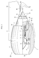
- a jet propulsion system 1 is provided with a jet engine 7 that has a cylindrical casing 2, a cylindrical partition wall 3 that is inserted in the casing while protruding partially from a trailing edge 2a of the casing 2, and a compressor 4 that compresses air that is taken into the cylindrical partition wall 3, with the inside of the cylindrical partition wall 3 serving as a duct 5 in which a high-speed core stream X flows, and the space between the cylindrical partition wall 3 and the casing 2 serving as a duct 6 in which a low-speed bypass stream Y flows, a pylon 8 that has a projection portion 8A that extends beyond the casing 2 to the downstream of the core stream X and the bypass stream Y to connect the casing 2 and the wing of an airplane not illustrated, and a noise reducing device 10.
- the jet engine 7 is provided with a fan 11, a compressor 4, a combustor 12, and a turbine 13, which are successively arrange along the central axis line C1 from the upstream to the downstream.
- the opening on the upstream of the casing 2 serves as an air intake 2A that takes in air A.
- bypass stream discharge outlet 2B that discharges the bypass stream Y.
- the bypass stream Y consists of the air A that is not taken into the compressor 4, and is a low-speed fluid that flows between the cylindrical partition wall 3 and the casing 2.
- the core stream X is a fluid that is exhausted from the turbine 13 and flows in the cylindrical partition wall 3, and is a fluid of a higher speed than the bypass stream Y.
- the opening on the downstream of the cylindrical partition wall 3 serves as a core stream discharge outlet 3A that discharges this core stream X.
- the ambient air stream Z is a low-speed fluid that flows on the outer side of the bypass stream Y, along the outer side of the casing 2.
- the casing 2 and the cylindrical partition wall 3 of the jet engine 7 both consist of cylindrical members.
- the casing 2 forms the outer shape of the jet engine 7, and covers the outer periphery of the cylindrical partition wall 3.
- the cylindrical partition wall 3 is arranged shifted somewhat downstream along the direction of the central axis line C1 with respect to the casing 2, and defines the duct 5 in which the core stream X flows and the duct 6 in which the bypass stream Y flows.
- the fan 11 is disposed upstream of the cylindrical partition wall 3, in the vicinity of the upstream end portion in the casing 2, and takes in the air A from the outside.
- the compressor 4 is disposed in the vicinity of the upstream end portion in the cylindrical partition wall 3, and takes in and compresses a portion of the air A that the fan 11 has taken in.
- the combustor 12 is arranged on the downstream of the compressor 4 in the cylindrical partition wall 3, and mixes fuel with the air A that the compressor 4 has compressed, combusts the mixture, and discharges the combustion gas.
- the turbine 13 is arranged on the downstream of the combustor 12 in the cylindrical partition wall 3, and drives the fan 11 and the compressor 4 by the combustion gas that the combustor 12 discharges.
- the pylon 8 is a member that extends in a direction perpendicular to the central axis line C1 of the casing 2 and the cylindrical partition wall 3, and supports the downstream end portions of the casing 2 and the cylindrical partition wall 3 from the outside.
- the pylon 8 has a projection portion 8A that extends further to the downstream than the casing 2, and it is arranged so as to project downward from the wing of an airplane not shown, and supports the jet engine 7 in a suspending manner.
- a noise reducing device 10 is provided with a plurality of microjet nozzles 15 that are arranged at the downstream end portion 3a of the cylindrical partition wall 3, and a plurality of pylon-caused noise reducing nozzles (nozzles) 16 that are disposed on the downstream end portion 8a of the projection portion 8A of the pylon 8.
- Each microjet nozzle 15 and the compressor 4 are connected by a supply channel 18 in which a valve 17 is disposed midway, and so a portion of the air that is discharged from the compressor 4 is injected from the microjet nozzle 15.
- the plurality of micro jet nozzles 15 are arranged on the downstream end portion 3a of the cylindrical partition wall 3 in the state of being separated by a predetermined interval in the circumferential direction, so as to inject the air toward the region where the core stream X and the bypass stream Y merge.
- the pylon-caused noise reducing nozzles 16 are connected with supply channels not shown that are connected to the compressor 4, whereby a portion of the air that is discharged from the compressor 4 is injected.
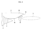
- the plurality of the pylon-caused noise reducing nozzles 16 are arranged in the vicinity of the downstream end portion 8a of the projection portion 8A of the pylon 8 so as to inject air toward a mixing layer (noise generation source) S shown in FIG. 2 that is produced by the mutual approach of the core stream X and the ambient air stream Z that occurs on the outside of the bypass stream Y.
- the aforementioned mixing layer (noise generation source) S refers to the location where, when measuring the noise level (sound pressure level) in the vicinity of the jet engine 7 at each frequency, the difference in sound pressure level between the case of the jet engine 7 being attached to a wing of an airplane via the pylon 8, and the case of it being attached without the pylon 8 is above a predetermined level.
- FIG 7 is an example of a sound pressure level measurement result that shows the sound pressure level for the case of a pylon ( ⁇ ) being as much as 4 dB greater than the case of no pylon ( ⁇ ) in the vicinity of the jet engine 7 due to the effect of the mixing layer (noise generation source) S.
- the air A is taken in from the air intake 2A by the rotation of the fan 11. A portion of this air A is compressed by the compressor 4, mixed with fuel by the combustor 12, and combusted. Drive power of the fan 11 and the compressor 4 is generated in the turbine 13 by the combustion gas that is discharged from the combustor 12. Thereafter, the fan 11 rotates and the air A is taken in by the drive power that is generated by the turbine 13.
- the core stream X flows in the duct 5 in the cylindrical partition wall 3 and is discharged from the core stream discharge outlet 3A.
- the bypass stream Y flows in the duct 6 between the cylindrical partition wall 3 and the casing 2, and is discharged from the bypass stream discharge outlet 2B. At this time, thrust is obtained, and the airplane takes off.
- the air that is injected from the pylon-caused noise reducing nozzles 16 reaches mixing layer S from the downstream end portion 8a of the projection portion 8A of the pylon 8, thereby causing the turbulence of the mixing layer S to spread.
- the air amount is suitably adjusted by the valve 17, in accordance with the operation state of the jet engine 7. In this way, the noise caused by the turbulence in the mixing layer S is reduced.
- the pylon-caused noise reducing nozzles 16 are arranged on the downstream end portion 8a of the projection portion 8A of the pylon 8, it is possible to reliably inject air into the mixing layer S, which is the noise generation source that occurs at a position near the downstream end portion 8a of the projection portion 8A of the pylon 8, it is possible to more favorably disperse the mixing layer S.
- the air that is injected from the pylon-caused noise reducing nozzles 16 is supplied from the compressor 4, it is possible to inject compressed air into the mixing layer S, which is the noise generation source, and it is possible to more favorably disperse the mixing layer S.
- the second embodiment and the first embodiment differ on the point of the pylon-caused noise reducing nozzles 16 of a jet propulsion system 20 and a noise reducing device 21 being arranged on an opposing portion 8b to the cylindrical partition wall 3 (engine rotational central axis) in the projection portion 8A of the pylon 8.
- each pylon-caused noise reducing nozzle 16 is oriented from the opposing portion 8b to the mixing layer S in the same manner as the first embodiment.
- the jet propulsion system 20 and the noise reducing device 21 even from the aforementioned opposing portion 8b in the projection portion 8A of the pylon 8, it is possible to reliably inject air into the mixing layer S that is the noise generation source, and it is possible to more favorably disperse the mixing layer S.
- the third embodiment and the first embodiment differ on the point of the pylon-caused noise reducing nozzles 16 of the jet propulsion system 22 and the noise reducing device 23 being arranged on a downstream end portion 3a of the cylindrical partition wall 3 in the vicinity of the pylon 8, instead of at the pylon 8.
- the pylon-caused noise reducing nozzles 16, together with the microjet nozzles 15, are disposed at symmetrical positions centered on an axial line C2 that is perpendicular to the central axis line C1 of the casing 2 and the cylindrical partition wall 3 so as to be concentrated in the vicinity of the pylon 8.
- the pylon-caused noise reducing nozzles 16 are pointed at the mixing layer S in the same manner as the other embodiments, unlike the microjet nozzles 15.
- the noise reducing device is provided with the microjet nozzles 15, but it may also be provided with another means, provided it reduces the noise that is generated by the merging of the core stream X and the bypass stream Y Also, a portion of the air discharged from the compressor 4 is injected, but it is also possible to supply air from another supply means, and moreover, it is not limited to air, and may be a liquid such as water.
- the air supply to the microjet nozzles 15 and the pylon-caused noise reducing nozzles 16 may consist of individual supply channels or a supply channel that is branched midway. Moreover, when supplying air to the microjet nozzles 15 and the pylon-caused noise reducing nozzles 16 individually, the timing of the injection may be staggered.
- the pylon is not limited to being on the lower side of the wing of an airplane, and may be disposed projecting in a horizontal direction or upward direction.
Landscapes
- Engineering & Computer Science (AREA)
- Chemical & Material Sciences (AREA)
- Combustion & Propulsion (AREA)
- Mechanical Engineering (AREA)
- General Engineering & Computer Science (AREA)
- Aviation & Aerospace Engineering (AREA)
- Structures Of Non-Positive Displacement Pumps (AREA)
- Jet Pumps And Other Pumps (AREA)
Abstract
Description
- The present invention relates to a noise reducing device for a jet engine and to a jet propulsion system.
- Priority is claimed on Japanese Patent Application No.
2008-42656, filed February 25, 2008 - A jet engine for an aircraft is constituted by the successive arrangement of a fan that takes in air, a compressor that takes in and compresses a portion of the air that the fan has taken in, a combustor that mixes the air that the compressor has compressed and fuel and causes a combustion, and a turbine that drives the fan and the compressor with the combustion gas of the combustor.
- The compressor, the combustor and the turbine are allocated in a cylindrical partition wall, and the fan is allocated in the upstream of the cylindrical partition wall. A large portion of the air that the fan takes in passes along a bypass duct that is provided in a space which exists between the cylindrical partition wall and a casing that covers the outer periphery of the cylindrical partition wall. The air that passes through this bypass duct (bypass stream) is discharged so as to surround the outer circumference of the exhaust air of the turbine (core stream), and merges with the core stream.
- The region where this core stream and bypass stream merge serves as a noise generation source, leading to the generation of noise. In order to reduce this noise, it has been proposed to have a plurality of pyramidal bodies arranged on a downstream end portion of a cylindrical partition wall to guide a portion of the high-speed core stream and the low-speed bypass stream in mutually different directions, and efficiently mix the fluids that flow on the inner side and the outer side of the cylindrical partition wall (for example, refer to
Patent Document 1 and Non-Patent Document). Thereby, the core stream and the bypass stream are suitably mixed by the generation of a vortex, and it is possible to reduce the noise. - However, since the pyramidal bodies are permanently fixed to the cylindrical partition wall, the core stream and the bypass stream end up being mixed not only at the time of takeoff but during cruising as well, and thus more than needed, leading to the problem of a reduction in thrust during cruising. Therefore, it has been proposed to arrange nozzles on the cylindrical partition wall, and by suitably injecting air toward the merging portion of the core stream and the bypass stream, the mixture state is adjusted (for example, refer to Non-Patent Document 2).
- Jet engines are mounted to airplane wings via a pylon.
- In the downstream region of this pylon, as shown in
FIG. 6 , the core stream X is deflected by turbulence in the bypass stream Y so that a low-speed ambient air stream Z that is further outside the core stream X and the bypass stream Y approaches. At this time, since the speed differential between the core stream X and the ambient air stream Z is large, a high shearing stress region with rapid fluctuations in speed is produced in the boundary region, and thus serves as another noise generation source in addition to the aforementioned noise generation source. - [Patent Document 1] Japanese Unexamined Patent Application, First Publication No.
2003-172205 - [Non-Patent Document 1] Steven J. Massey et al., "Computational Analyses of Propulsion Aeroacoustics for Mixed Flow Nozzle Pylon Installation at Takeoff", NASA/CR-2001-211-56, September 2001.
- [Non-Patent Document 2] Brenton Greska et al., "The Effects of Microjet Injection on an F404 Jet Engine", AIAA 2005-3047, 11th AIAA/CEAS Aeroacoustics Conference (26th AIAA Aeroacoustics Conference), 23-25 May 2005.
- Accordingly, in the nozzles disclosed in
Non-Patent Document 2 above, it is not possible to reduce the noise from the aforementioned new noise generation source, and the noise reduction effect is insufficient. - The present invention was achieved in view of the above circumstances, and has as its object to provide a noise reducing device for a jet engine and a jet propulsion system that can reduce the noise that is produced as a result of the jet engine being connected to the wing of an airplane by a pylon.
- The present invention adopts the following means in order to solve the aforementioned problems.
- The noise reducing device of the present invention is a noise reducing device in a jet engine that has a cylindrical casing, a cylindrical partition wall that is inserted in the casing while protruding partially from a trailing edge of the casing, and a compressor that compresses air that is taken into the cylindrical partition wall, with the inside of the cylindrical partition wall serving as a duct in which a core stream of high-speed air flows, and the space between the cylindrical partition wall and the casing serving as a duct in which a bypass stream of low-speed air flows, and being connected with a wing of an airplane by a pylon that has a projection portion that extends beyond the casing to the downstream of the core stream and the bypass stream, the noise reducing device includes a nozzle, disposed at the pylon on the downstream of the core stream, that injects a fluid toward a noise generation source that is produced from the mutual approach of an ambient air stream that is produced outside of the bypass stream and the core stream.
- The present invention can inject a fluid from the nozzle toward a mixing layer that is a noise generation source that is produced by the mutual approach of the core stream and the ambient air stream, which have a large speed differential downstream of the pylon, and by dispersing turbulence of the mixing layer, can reduce the noise that is caused by the turbulence in the mixing layer.
- Also, in the noise reducing device of the present invention, the nozzle is arranged on the downstream end portion of the projection portion of the pylon.
- This invention can reliably inject a fluid in the noise generation source that is produced at a position near the downstream end portion of the projection portion of the pylon, and can more preferably disperse the mixing layer.
- Also, in the noise reducing device of the present invention, the nozzle is arranged at the opposing portion to the engine rotational central axis in the projection portion of the pylon.
- This invention can reliably inject a fluid into the noise generation source even from the aforementioned opposing portion in the projection portion of the pylon, and can more preferably disperse the mixing layer.
- Also, in the noise reducing device of the present invention, the nozzle is arranged on the downstream end portion of the cylindrical partition wall in the vicinity of the pylon.
- This invention, even if the nozzle is not arranged on the pylon, can inject a fluid from the downstream end portion of the cylindrical partition wall, and can disperse the turbulence in the mixing layer.
- Also, in the noise reducing device of the present invention, the fluid that is injected from the nozzle is air that is supplied from the compressor to the nozzle.
- This invention can inject air that is compressed to the noise generation source, and can more preferably disperse the mixing layer.
- The jet propulsion system of the present invention is provided with a jet engine having a cylindrical casing, a cylindrical partition wall that is inserted in the casing while protruding partially from a downstream end portion of the casing, a compressor that compresses air that is taken into the cylindrical partition wall, with the inside of the cylindrical partition wall serving as a duct in which a high-speed core stream flows, and the space between the cylindrical partition wall and the casing serving as a duct in which a low-speed bypass stream flows; a pylon that has a projection portion that extends beyond the casing to the downstream of the core stream and the bypass stream to connect the casing and a wing of an airplane; and the noise reducing device of the present invention.
- According to the present invention, it is possible to favorably reduce the noise produced by the connection of a jet engine to a wing of an airplane via a pylon.
-
-
FIG. 1 is a schematic cross-sectional drawing that shows the schematic configuration of the jet propulsion system and the noise reducing device of the first embodiment of the present invention. -
FIG. 2 is an explanatory drawing that shows the relationship between the jet propulsion system and the noise reducing device of the first embodiment of the present invention and the mixing layer that is a noise generation source. -
FIG 3 is a schematic cross-sectional drawing that shows the schematic configuration of the jet propulsion system and the noise reducing device of the second embodiment of the present invention. -
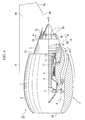
FIG. 4 is a schematic cross-sectional drawing that shows the schematic configuration of the jet propulsion system and the noise reducing device of the third embodiment of the present invention. -
FIG. 5 is a cross-sectional view along lines V-V ofFIG. 4 . -
FIG. 6 is a pattern view that shows the core stream, a bypass stream, and an ambient air stream that are discharged from a conventional jet engine. -
FIG. 7 is a graph that shows the difference in sound pressure levels generated by the noise generation source. -
- 1, 20, 22
- jet propulsion system
- 2
- casing
- 2a
- trailing edge
- 3
- cylindrical partition wall
- 4
- compressor
- 5, 6
- ducts
- 7 jet
- engine
- 8
- pylon
- 8A
- projection portion
- 8a
- downstream end portion
- 8b
- opposing portion
- 10, 21, 23
- noise reducing device
- 15
- microjet nozzle
- 16
- pylon-caused noise reducing nozzle (nozzle)
- A first embodiment of the present invention shall be described with reference to
FIG 1 andFIG. 2 . - A
jet propulsion system 1 according to the present embodiment, as shown inFIG 1 , is provided with ajet engine 7 that has acylindrical casing 2, acylindrical partition wall 3 that is inserted in the casing while protruding partially from a trailingedge 2a of thecasing 2, and acompressor 4 that compresses air that is taken into thecylindrical partition wall 3, with the inside of thecylindrical partition wall 3 serving as aduct 5 in which a high-speed core stream X flows, and the space between thecylindrical partition wall 3 and thecasing 2 serving as aduct 6 in which a low-speed bypass stream Y flows, apylon 8 that has aprojection portion 8A that extends beyond thecasing 2 to the downstream of the core stream X and the bypass stream Y to connect thecasing 2 and the wing of an airplane not illustrated, and anoise reducing device 10. - The
jet engine 7 is provided with afan 11, acompressor 4, acombustor 12, and aturbine 13, which are successively arrange along the central axis line C1 from the upstream to the downstream. - The opening on the upstream of the
casing 2 serves as anair intake 2A that takes in air A. - The opening on the downstream of the
casing 2 serves as a bypassstream discharge outlet 2B that discharges the bypass stream Y. Of the air A that is taken in from theair intake 2A, the bypass stream Y consists of the air A that is not taken into thecompressor 4, and is a low-speed fluid that flows between thecylindrical partition wall 3 and thecasing 2. - The core stream X is a fluid that is exhausted from the
turbine 13 and flows in thecylindrical partition wall 3, and is a fluid of a higher speed than the bypass stream Y. The opening on the downstream of thecylindrical partition wall 3 serves as a corestream discharge outlet 3A that discharges this core stream X. The ambient air stream Z is a low-speed fluid that flows on the outer side of the bypass stream Y, along the outer side of thecasing 2. - The
casing 2 and thecylindrical partition wall 3 of thejet engine 7 both consist of cylindrical members. Thecasing 2 forms the outer shape of thejet engine 7, and covers the outer periphery of thecylindrical partition wall 3. - The
cylindrical partition wall 3 is arranged shifted somewhat downstream along the direction of the central axis line C1 with respect to thecasing 2, and defines theduct 5 in which the core stream X flows and theduct 6 in which the bypass stream Y flows. - The
fan 11 is disposed upstream of thecylindrical partition wall 3, in the vicinity of the upstream end portion in thecasing 2, and takes in the air A from the outside. Thecompressor 4 is disposed in the vicinity of the upstream end portion in thecylindrical partition wall 3, and takes in and compresses a portion of the air A that thefan 11 has taken in. - The
combustor 12 is arranged on the downstream of thecompressor 4 in thecylindrical partition wall 3, and mixes fuel with the air A that thecompressor 4 has compressed, combusts the mixture, and discharges the combustion gas. Theturbine 13 is arranged on the downstream of thecombustor 12 in thecylindrical partition wall 3, and drives thefan 11 and thecompressor 4 by the combustion gas that thecombustor 12 discharges. - The
pylon 8 is a member that extends in a direction perpendicular to the central axis line C1 of thecasing 2 and thecylindrical partition wall 3, and supports the downstream end portions of thecasing 2 and thecylindrical partition wall 3 from the outside. Thepylon 8 has aprojection portion 8A that extends further to the downstream than thecasing 2, and it is arranged so as to project downward from the wing of an airplane not shown, and supports thejet engine 7 in a suspending manner. - A
noise reducing device 10 is provided with a plurality ofmicrojet nozzles 15 that are arranged at thedownstream end portion 3a of thecylindrical partition wall 3, and a plurality of pylon-caused noise reducing nozzles (nozzles) 16 that are disposed on thedownstream end portion 8a of theprojection portion 8A of thepylon 8. - Each
microjet nozzle 15 and thecompressor 4 are connected by asupply channel 18 in which avalve 17 is disposed midway, and so a portion of the air that is discharged from thecompressor 4 is injected from themicrojet nozzle 15. The plurality ofmicro jet nozzles 15 are arranged on thedownstream end portion 3a of thecylindrical partition wall 3 in the state of being separated by a predetermined interval in the circumferential direction, so as to inject the air toward the region where the core stream X and the bypass stream Y merge. - Similarly to the
microjet nozzles 15, the pylon-causednoise reducing nozzles 16 are connected with supply channels not shown that are connected to thecompressor 4, whereby a portion of the air that is discharged from thecompressor 4 is injected. The plurality of the pylon-causednoise reducing nozzles 16 are arranged in the vicinity of thedownstream end portion 8a of theprojection portion 8A of thepylon 8 so as to inject air toward a mixing layer (noise generation source) S shown inFIG. 2 that is produced by the mutual approach of the core stream X and the ambient air stream Z that occurs on the outside of the bypass stream Y. Note that the aforementioned mixing layer (noise generation source) S refers to the location where, when measuring the noise level (sound pressure level) in the vicinity of thejet engine 7 at each frequency, the difference in sound pressure level between the case of thejet engine 7 being attached to a wing of an airplane via thepylon 8, and the case of it being attached without thepylon 8 is above a predetermined level.FIG 7 is an example of a sound pressure level measurement result that shows the sound pressure level for the case of a pylon (□) being as much as 4 dB greater than the case of no pylon (◆) in the vicinity of thejet engine 7 due to the effect of the mixing layer (noise generation source) S. - Next, the operation of the
jet propulsion system 1 and thenoise reducing device 10 according to the present invention shall be described. - During the takeoff of an airplane, first the air A is taken in from the
air intake 2A by the rotation of thefan 11. A portion of this air A is compressed by thecompressor 4, mixed with fuel by thecombustor 12, and combusted. Drive power of thefan 11 and thecompressor 4 is generated in theturbine 13 by the combustion gas that is discharged from thecombustor 12. Thereafter, thefan 11 rotates and the air A is taken in by the drive power that is generated by theturbine 13. - By the aforementioned operation, the core stream X flows in the
duct 5 in thecylindrical partition wall 3 and is discharged from the corestream discharge outlet 3A. Also, the bypass stream Y flows in theduct 6 between thecylindrical partition wall 3 and thecasing 2, and is discharged from the bypassstream discharge outlet 2B. At this time, thrust is obtained, and the airplane takes off. - At this time, by opening the
valve 17, air is injected from each of themicrojet nozzles 15 and the pylon-causednoise reducing nozzles 16. The air that is injected from themicrojet nozzles 15 reaches the region where the discharged core stream X and the bypass stream Y merge, and is made to favorably mix with both. In this way, the noise that is produced by the merging of the core stream X and the bypass stream Y is reduced. - Meanwhile, the air that is injected from the pylon-caused
noise reducing nozzles 16 reaches mixing layer S from thedownstream end portion 8a of theprojection portion 8A of thepylon 8, thereby causing the turbulence of the mixing layer S to spread. At this time, the air amount is suitably adjusted by thevalve 17, in accordance with the operation state of thejet engine 7. In this way, the noise caused by the turbulence in the mixing layer S is reduced. - When the airplane has reached a predetermined altitude, the injection of air from the
microjet nozzles 15 and the pylon-causednoise reducing nozzles 16 is stopped by closing thevalve 17, and a predetermined cruising state is ensured. - According to this
jet propulsion system 1 and thenoise reducing device 10, since air from the pylon-causednoise reducing nozzles 16 is injected toward the mixing layer S, which is the noise generation source that is produced by the mutual approach of the core stream X and the ambient air stream Z that have a large velocity differential downstream of thepylon 8, it is possible to disperse the turbulence of the mixing layer S, and reduce the noise caused by the turbulence in the mixing layer S. Accordingly, it is possible to favorably reduce the noise produced by the connection of thejet engine 7 to the wing of an airplane via thepylon 8. - In particular, since the pylon-caused
noise reducing nozzles 16 are arranged on thedownstream end portion 8a of theprojection portion 8A of thepylon 8, it is possible to reliably inject air into the mixing layer S, which is the noise generation source that occurs at a position near thedownstream end portion 8a of theprojection portion 8A of thepylon 8, it is possible to more favorably disperse the mixing layer S. - Also, since the air that is injected from the pylon-caused
noise reducing nozzles 16 is supplied from thecompressor 4, it is possible to inject compressed air into the mixing layer S, which is the noise generation source, and it is possible to more favorably disperse the mixing layer S. - Next, a second embodiment shall be described with reference to
FIG. 3 . - Note that those constituent elements that are the same as in the first embodiment above are denoted by the same reference numerals, and descriptions thereof are omitted.
- The second embodiment and the first embodiment differ on the point of the pylon-caused
noise reducing nozzles 16 of ajet propulsion system 20 and anoise reducing device 21 being arranged on an opposingportion 8b to the cylindrical partition wall 3 (engine rotational central axis) in theprojection portion 8A of thepylon 8. - The distal end of each pylon-caused
noise reducing nozzle 16 is oriented from the opposingportion 8b to the mixing layer S in the same manner as the first embodiment. - According to the
jet propulsion system 20 and thenoise reducing device 21, even from the aforementioned opposingportion 8b in theprojection portion 8A of thepylon 8, it is possible to reliably inject air into the mixing layer S that is the noise generation source, and it is possible to more favorably disperse the mixing layer S. - Next, a third embodiment shall be described with reference to
FIG. 4 andFIG. 5 . - Note that those constituent elements that are the same as in the other embodiments above are denoted by the same reference numerals, and descriptions thereof are omitted.
- The third embodiment and the first embodiment differ on the point of the pylon-caused
noise reducing nozzles 16 of thejet propulsion system 22 and thenoise reducing device 23 being arranged on adownstream end portion 3a of thecylindrical partition wall 3 in the vicinity of thepylon 8, instead of at thepylon 8. - That is, the pylon-caused
noise reducing nozzles 16, together with themicrojet nozzles 15, are disposed at symmetrical positions centered on an axial line C2 that is perpendicular to the central axis line C1 of thecasing 2 and thecylindrical partition wall 3 so as to be concentrated in the vicinity of thepylon 8. Note that the pylon-causednoise reducing nozzles 16 are pointed at the mixing layer S in the same manner as the other embodiments, unlike themicrojet nozzles 15. - According to this
jet propulsion system 22 and thenoise reducing device 23, even if the pylon-causednoise reducing nozzles 16 are not disposed on thepylon 8, it is possible to disperse the turbulence of the mixing layer S by injecting air from thedownstream end portion 3a of thecylindrical partition wall 3 into the mixing layer S. - Note that the technical scope of the present invention is not limited to the aforementioned embodiments, and various changes can be made without departing from the scope of the present invention.
- For example, in the aforementioned embodiments, the noise reducing device is provided with the
microjet nozzles 15, but it may also be provided with another means, provided it reduces the noise that is generated by the merging of the core stream X and the bypass stream Y Also, a portion of the air discharged from thecompressor 4 is injected, but it is also possible to supply air from another supply means, and moreover, it is not limited to air, and may be a liquid such as water. - Also, the air supply to the
microjet nozzles 15 and the pylon-causednoise reducing nozzles 16 may consist of individual supply channels or a supply channel that is branched midway. Moreover, when supplying air to themicrojet nozzles 15 and the pylon-causednoise reducing nozzles 16 individually, the timing of the injection may be staggered. - Also, the pylon is not limited to being on the lower side of the wing of an airplane, and may be disposed projecting in a horizontal direction or upward direction.
- According to the present invention, it is possible to favorably reduce the noise produced by the connection of a jet engine to the wing of an airplane via a pylon.
Claims (6)
- A noise reducing device in a jet engine that has a cylindrical casing, a cylindrical partition wall that is inserted in the casing while protruding partially from a trailing edge of the casing, and a compressor that compresses air that is taken into the cylindrical partition wall, with the inside of the cylindrical partition wall serving as a duct in which a core stream of high-speed air flows, and the space between the cylindrical partition wall and the casing serving as a duct in which a bypass stream of low-speed air flows, and being connected with a wing of an airplane by a pylon that has a projection portion that extends beyond the casing to the downstream of the core stream and the bypass stream,
the noise reducing device comprising a nozzle, disposed at the pylon on the downstream of the core stream, that injects a fluid toward a noise generation source that is produced from the mutual approach of an ambient air stream that is produced outside of the bypass stream and the core stream. - The noise reducing device according to claim 1, wherein the nozzle is arranged on the downstream end portion of the projection portion of the pylon.
- The noise reducing device according to claim 1, wherein the nozzle is arranged at the opposing portion to the engine rotational central axis in the projection portion of the pylon.
- The noise reducing device according to claim 1, wherein the nozzle is arranged on the downstream end portion of the cylindrical partition wall in the vicinity of the pylon.
- The noise reducing device according to any one of claims 1 to 4, wherein the fluid that is injected from the nozzle is air that is supplied from the compressor to the nozzle.
- A jet propulsion system comprising:a jet engine having a cylindrical casing, a cylindrical partition wall that is inserted in the casing while protruding partially from a downstream end portion of the casing, a compressor that compresses air that is taken into the cylindrical partition wall, with the inside of the cylindrical partition wall serving as a duct in which a high-speed core stream flows, and the space between the cylindrical partition wall and the casing serving as a duct in which a low-speed bypass stream flows;a pylon that has a projection portion that extends beyond the casing to the downstream of the core stream and the bypass stream to connect the casing and a wing of an airplane; andthe noise reducing device according to any one of claims 1 to 5.
Applications Claiming Priority (2)
| Application Number | Priority Date | Filing Date | Title |
|---|---|---|---|
| JP2008042656 | 2008-02-25 | ||
| PCT/JP2009/053386 WO2009107646A1 (en) | 2008-02-25 | 2009-02-25 | Noise reducing device, and jet propulsion system |
Publications (3)
| Publication Number | Publication Date |
|---|---|
| EP2256327A1 true EP2256327A1 (en) | 2010-12-01 |
| EP2256327A4 EP2256327A4 (en) | 2012-05-16 |
| EP2256327B1 EP2256327B1 (en) | 2019-09-04 |
Family
ID=41016035
Family Applications (1)
| Application Number | Title | Priority Date | Filing Date |
|---|---|---|---|
| EP09715023.9A Active EP2256327B1 (en) | 2008-02-25 | 2009-02-25 | Noise reducing device, and jet propulsion system |
Country Status (4)
| Country | Link |
|---|---|
| US (1) | US8904795B2 (en) |
| EP (1) | EP2256327B1 (en) |
| JP (1) | JP4862961B2 (en) |
| WO (1) | WO2009107646A1 (en) |
Cited By (2)
| Publication number | Priority date | Publication date | Assignee | Title |
|---|---|---|---|---|
| US20120228054A1 (en) * | 2009-10-28 | 2012-09-13 | Tanaka Nozomi | Noise reduction system with chamber |
| FR3016411A1 (en) * | 2014-01-10 | 2015-07-17 | Snecma | AIRCRAFT PROPULSIVE ASSEMBLY WITH NOISE REDUCTION MEANS |
Families Citing this family (9)
| Publication number | Priority date | Publication date | Assignee | Title |
|---|---|---|---|---|
| FR2929337B1 (en) * | 2008-03-31 | 2012-06-01 | Airbus France | SECONDARY JET DEVICE FOR REDUCING NOISE GENERATED BY AN AIRCRAFT REACTOR |
| EP2495423B1 (en) * | 2009-10-28 | 2016-05-18 | IHI Corporation | Noise reduction device |
| FR2956855B1 (en) * | 2010-02-26 | 2012-07-27 | Snecma | DEVICE FOR REDUCING WALL NOISE ON PYLONES OF TURBOREACTORS |
| US9022311B2 (en) * | 2010-08-20 | 2015-05-05 | The United States Of America As Represented By The Administrator Of The National Aeronautics And Space Administration | Active aircraft pylon noise control system |
| RU2731780C2 (en) * | 2015-03-26 | 2020-09-08 | Сафран Эркрафт Энджинз | Device with grids for ejection of microjets to reduce noise of jet stream of gas turbine engine |
| FR3037318B1 (en) * | 2015-06-15 | 2017-06-30 | Snecma | AIRCRAFT PROPULSIVE ASSEMBLY COMPRISING A NON-CARBONATED BLOWER TURBOREACTOR AND A PENSION PYLON |
| US10829206B2 (en) | 2016-02-10 | 2020-11-10 | General Electric Company | Wing leading edge features to attenuate propeller wake-wing acoustic interactions |
| US11365704B2 (en) * | 2018-02-27 | 2022-06-21 | New York University In Abu Dhabi Corportion | Directionally targeted jet noise reduction system and method |
| GB2578447A (en) * | 2018-10-26 | 2020-05-13 | Airbus Operations Ltd | Aircraft assembly with a hot-air exhaust outlet |
Family Cites Families (17)
| Publication number | Priority date | Publication date | Assignee | Title |
|---|---|---|---|---|
| GB1209723A (en) | 1969-06-14 | 1970-10-21 | Rolls Royce | Improvements in or relating to boundary layer air flow |
| US5156353A (en) * | 1987-04-13 | 1992-10-20 | General Electric Company | Aircraft pylon |
| US4917336A (en) * | 1988-02-19 | 1990-04-17 | The Boeing Company | Mounting assembly for unducted prop engine and method |
| US5092425A (en) * | 1990-04-02 | 1992-03-03 | The United States Of America As Represented By The Secretary Of The Air Force | Jet noise suppressor and method |
| US7159383B2 (en) * | 2000-10-02 | 2007-01-09 | Rohr, Inc. | Apparatus, method and system for gas turbine engine noise reduction |
| US6679048B1 (en) * | 2000-10-24 | 2004-01-20 | Lockheed Martin Corporation | Apparatus and method for controlling primary fluid flow using secondary fluid flow injection |
| JP3962981B2 (en) | 2001-12-07 | 2007-08-22 | 石川島播磨重工業株式会社 | Jet jet mixer |
| DE60329905D1 (en) * | 2002-02-22 | 2009-12-17 | Nordam Group Inc | DOUBLE MIXER exhaust nozzle |
| GB0226228D0 (en) * | 2002-11-09 | 2002-12-18 | Rolls Royce Plc | Suppression of part of the noise from a gas turbine engine |
| US7055329B2 (en) * | 2003-03-31 | 2006-06-06 | General Electric Company | Method and apparatus for noise attenuation for gas turbine engines using at least one synthetic jet actuator for injecting air |
| US7093423B2 (en) * | 2004-01-20 | 2006-08-22 | General Electric Company | Methods and apparatus for operating gas turbine engines |
| US7246481B2 (en) * | 2004-03-26 | 2007-07-24 | General Electric Company | Methods and apparatus for operating gas turbine engines |
| FR2901321B1 (en) * | 2006-05-18 | 2011-08-12 | Aircelle Sa | METHOD FOR HOMOGENIZING AIR FROM TURBOJET OUTPUT TO LOWER GENERATED NOISE |
| FR2904663B1 (en) * | 2006-08-01 | 2012-02-03 | Snecma | DOUBLE FLOW TURBOMACHINE WITH ARTIFICIAL VARIATION OF ITS COLLEGE SECTION |
| US7966826B2 (en) * | 2007-02-14 | 2011-06-28 | The Boeing Company | Systems and methods for reducing noise from jet engine exhaust |
| US8651426B2 (en) * | 2010-07-01 | 2014-02-18 | Rolls-Royce Plc | Jet engine installation |
| US9022311B2 (en) * | 2010-08-20 | 2015-05-05 | The United States Of America As Represented By The Administrator Of The National Aeronautics And Space Administration | Active aircraft pylon noise control system |
-
2009
- 2009-02-25 US US12/918,899 patent/US8904795B2/en active Active
- 2009-02-25 JP JP2010500708A patent/JP4862961B2/en active Active
- 2009-02-25 EP EP09715023.9A patent/EP2256327B1/en active Active
- 2009-02-25 WO PCT/JP2009/053386 patent/WO2009107646A1/en not_active Ceased
Cited By (3)
| Publication number | Priority date | Publication date | Assignee | Title |
|---|---|---|---|---|
| US20120228054A1 (en) * | 2009-10-28 | 2012-09-13 | Tanaka Nozomi | Noise reduction system with chamber |
| US8813907B2 (en) * | 2009-10-28 | 2014-08-26 | Ihi Corporation | Noise reduction system with chamber |
| FR3016411A1 (en) * | 2014-01-10 | 2015-07-17 | Snecma | AIRCRAFT PROPULSIVE ASSEMBLY WITH NOISE REDUCTION MEANS |
Also Published As
| Publication number | Publication date |
|---|---|
| JP4862961B2 (en) | 2012-01-25 |
| EP2256327B1 (en) | 2019-09-04 |
| JPWO2009107646A1 (en) | 2011-07-07 |
| WO2009107646A1 (en) | 2009-09-03 |
| US8904795B2 (en) | 2014-12-09 |
| US20110000181A1 (en) | 2011-01-06 |
| EP2256327A4 (en) | 2012-05-16 |
Similar Documents
| Publication | Publication Date | Title |
|---|---|---|
| EP2256327B1 (en) | Noise reducing device, and jet propulsion system | |
| EP2098714B1 (en) | High bypass-ratio turbofan jet engine | |
| US10829232B2 (en) | Aircraft comprising a propulsion assembly including a fan on the rear of the fuselage | |
| CA2779149C (en) | Noise reduction system with chamber | |
| RU2435057C2 (en) | Turbofan gas turbine engine with adjustable fan outlet guide vanes (versions) | |
| EP3284942B1 (en) | Direct drive aft fan engine | |
| JP5492199B2 (en) | Dual tab exhaust nozzle | |
| JP4981624B2 (en) | Turbofan engine nozzle assembly and turbofan engine assembly | |
| US20180094605A1 (en) | Turbofan engine for a civil supersonic aircraft | |
| US9938901B2 (en) | Attachment pylon for a turbine engine | |
| US9644537B2 (en) | Free stream intake with particle separator for reverse core engine | |
| US10550704B2 (en) | High performance convergent divergent nozzle | |
| EP1485600A1 (en) | Duplex mixer exhaust nozzle | |
| US10337455B2 (en) | Fan nacelle inlet flow control | |
| CA1263242A (en) | Gas turbine outlet arrangement | |
| CN107923342B (en) | Aircraft propulsion assembly including thrust reverser | |
| US20130232981A1 (en) | Jet noise reduction using eduction effect | |
| US20150252751A1 (en) | Geared gas turbine engine integrated with a variable area fan nozzle with reduced noise | |
| JPWO2011052566A1 (en) | Noise reduction device | |
| US11920539B1 (en) | Gas turbine exhaust nozzle noise abatement | |
| EP3121430B1 (en) | A nacelle assembly |
Legal Events
| Date | Code | Title | Description |
|---|---|---|---|
| PUAI | Public reference made under article 153(3) epc to a published international application that has entered the european phase |
Free format text: ORIGINAL CODE: 0009012 |
|
| 17P | Request for examination filed |
Effective date: 20100903 |
|
| AK | Designated contracting states |
Kind code of ref document: A1 Designated state(s): AT BE BG CH CY CZ DE DK EE ES FI FR GB GR HR HU IE IS IT LI LT LU LV MC MK MT NL NO PL PT RO SE SI SK TR |
|
| AX | Request for extension of the european patent |
Extension state: AL BA RS |
|
| DAX | Request for extension of the european patent (deleted) | ||
| A4 | Supplementary search report drawn up and despatched |
Effective date: 20120416 |
|
| RIC1 | Information provided on ipc code assigned before grant |
Ipc: B64C 7/02 20060101ALI20120410BHEP Ipc: B64D 27/18 20060101ALI20120410BHEP Ipc: B64D 29/04 20060101ALI20120410BHEP Ipc: F02K 3/06 20060101ALI20120410BHEP Ipc: F02K 1/00 20060101ALI20120410BHEP Ipc: F02K 1/34 20060101AFI20120410BHEP Ipc: F02K 1/44 20060101ALI20120410BHEP Ipc: F02K 1/46 20060101ALI20120410BHEP |
|
| 17Q | First examination report despatched |
Effective date: 20130731 |
|
| STAA | Information on the status of an ep patent application or granted ep patent |
Free format text: STATUS: EXAMINATION IS IN PROGRESS |
|
| GRAP | Despatch of communication of intention to grant a patent |
Free format text: ORIGINAL CODE: EPIDOSNIGR1 |
|
| STAA | Information on the status of an ep patent application or granted ep patent |
Free format text: STATUS: GRANT OF PATENT IS INTENDED |
|
| INTG | Intention to grant announced |
Effective date: 20190503 |
|
| GRAS | Grant fee paid |
Free format text: ORIGINAL CODE: EPIDOSNIGR3 |
|
| GRAA | (expected) grant |
Free format text: ORIGINAL CODE: 0009210 |
|
| STAA | Information on the status of an ep patent application or granted ep patent |
Free format text: STATUS: THE PATENT HAS BEEN GRANTED |
|
| AK | Designated contracting states |
Kind code of ref document: B1 Designated state(s): AT BE BG CH CY CZ DE DK EE ES FI FR GB GR HR HU IE IS IT LI LT LU LV MC MK MT NL NO PL PT RO SE SI SK TR |
|
| REG | Reference to a national code |
Ref country code: GB Ref legal event code: FG4D |
|
| REG | Reference to a national code |
Ref country code: CH Ref legal event code: EP |
|
| REG | Reference to a national code |
Ref country code: AT Ref legal event code: REF Ref document number: 1175673 Country of ref document: AT Kind code of ref document: T Effective date: 20190915 |
|
| REG | Reference to a national code |
Ref country code: DE Ref legal event code: R096 Ref document number: 602009059697 Country of ref document: DE |
|
| REG | Reference to a national code |
Ref country code: IE Ref legal event code: FG4D |
|
| REG | Reference to a national code |
Ref country code: NL Ref legal event code: MP Effective date: 20190904 |
|
| REG | Reference to a national code |
Ref country code: LT Ref legal event code: MG4D |
|
| PG25 | Lapsed in a contracting state [announced via postgrant information from national office to epo] |
Ref country code: SE Free format text: LAPSE BECAUSE OF FAILURE TO SUBMIT A TRANSLATION OF THE DESCRIPTION OR TO PAY THE FEE WITHIN THE PRESCRIBED TIME-LIMIT Effective date: 20190904 Ref country code: BG Free format text: LAPSE BECAUSE OF FAILURE TO SUBMIT A TRANSLATION OF THE DESCRIPTION OR TO PAY THE FEE WITHIN THE PRESCRIBED TIME-LIMIT Effective date: 20191204 Ref country code: NO Free format text: LAPSE BECAUSE OF FAILURE TO SUBMIT A TRANSLATION OF THE DESCRIPTION OR TO PAY THE FEE WITHIN THE PRESCRIBED TIME-LIMIT Effective date: 20191204 Ref country code: FI Free format text: LAPSE BECAUSE OF FAILURE TO SUBMIT A TRANSLATION OF THE DESCRIPTION OR TO PAY THE FEE WITHIN THE PRESCRIBED TIME-LIMIT Effective date: 20190904 Ref country code: HR Free format text: LAPSE BECAUSE OF FAILURE TO SUBMIT A TRANSLATION OF THE DESCRIPTION OR TO PAY THE FEE WITHIN THE PRESCRIBED TIME-LIMIT Effective date: 20190904 Ref country code: LT Free format text: LAPSE BECAUSE OF FAILURE TO SUBMIT A TRANSLATION OF THE DESCRIPTION OR TO PAY THE FEE WITHIN THE PRESCRIBED TIME-LIMIT Effective date: 20190904 |
|
| PG25 | Lapsed in a contracting state [announced via postgrant information from national office to epo] |
Ref country code: LV Free format text: LAPSE BECAUSE OF FAILURE TO SUBMIT A TRANSLATION OF THE DESCRIPTION OR TO PAY THE FEE WITHIN THE PRESCRIBED TIME-LIMIT Effective date: 20190904 Ref country code: GR Free format text: LAPSE BECAUSE OF FAILURE TO SUBMIT A TRANSLATION OF THE DESCRIPTION OR TO PAY THE FEE WITHIN THE PRESCRIBED TIME-LIMIT Effective date: 20191205 Ref country code: ES Free format text: LAPSE BECAUSE OF FAILURE TO SUBMIT A TRANSLATION OF THE DESCRIPTION OR TO PAY THE FEE WITHIN THE PRESCRIBED TIME-LIMIT Effective date: 20190904 |
|
| REG | Reference to a national code |
Ref country code: AT Ref legal event code: MK05 Ref document number: 1175673 Country of ref document: AT Kind code of ref document: T Effective date: 20190904 |
|
| PG25 | Lapsed in a contracting state [announced via postgrant information from national office to epo] |
Ref country code: PT Free format text: LAPSE BECAUSE OF FAILURE TO SUBMIT A TRANSLATION OF THE DESCRIPTION OR TO PAY THE FEE WITHIN THE PRESCRIBED TIME-LIMIT Effective date: 20200106 Ref country code: EE Free format text: LAPSE BECAUSE OF FAILURE TO SUBMIT A TRANSLATION OF THE DESCRIPTION OR TO PAY THE FEE WITHIN THE PRESCRIBED TIME-LIMIT Effective date: 20190904 Ref country code: PL Free format text: LAPSE BECAUSE OF FAILURE TO SUBMIT A TRANSLATION OF THE DESCRIPTION OR TO PAY THE FEE WITHIN THE PRESCRIBED TIME-LIMIT Effective date: 20190904 Ref country code: RO Free format text: LAPSE BECAUSE OF FAILURE TO SUBMIT A TRANSLATION OF THE DESCRIPTION OR TO PAY THE FEE WITHIN THE PRESCRIBED TIME-LIMIT Effective date: 20190904 Ref country code: IT Free format text: LAPSE BECAUSE OF FAILURE TO SUBMIT A TRANSLATION OF THE DESCRIPTION OR TO PAY THE FEE WITHIN THE PRESCRIBED TIME-LIMIT Effective date: 20190904 Ref country code: AT Free format text: LAPSE BECAUSE OF FAILURE TO SUBMIT A TRANSLATION OF THE DESCRIPTION OR TO PAY THE FEE WITHIN THE PRESCRIBED TIME-LIMIT Effective date: 20190904 Ref country code: NL Free format text: LAPSE BECAUSE OF FAILURE TO SUBMIT A TRANSLATION OF THE DESCRIPTION OR TO PAY THE FEE WITHIN THE PRESCRIBED TIME-LIMIT Effective date: 20190904 |
|
| PG25 | Lapsed in a contracting state [announced via postgrant information from national office to epo] |
Ref country code: IS Free format text: LAPSE BECAUSE OF FAILURE TO SUBMIT A TRANSLATION OF THE DESCRIPTION OR TO PAY THE FEE WITHIN THE PRESCRIBED TIME-LIMIT Effective date: 20200224 Ref country code: CZ Free format text: LAPSE BECAUSE OF FAILURE TO SUBMIT A TRANSLATION OF THE DESCRIPTION OR TO PAY THE FEE WITHIN THE PRESCRIBED TIME-LIMIT Effective date: 20190904 Ref country code: SK Free format text: LAPSE BECAUSE OF FAILURE TO SUBMIT A TRANSLATION OF THE DESCRIPTION OR TO PAY THE FEE WITHIN THE PRESCRIBED TIME-LIMIT Effective date: 20190904 |
|
| REG | Reference to a national code |
Ref country code: DE Ref legal event code: R097 Ref document number: 602009059697 Country of ref document: DE |
|
| PLBE | No opposition filed within time limit |
Free format text: ORIGINAL CODE: 0009261 |
|
| STAA | Information on the status of an ep patent application or granted ep patent |
Free format text: STATUS: NO OPPOSITION FILED WITHIN TIME LIMIT |
|
| PG2D | Information on lapse in contracting state deleted |
Ref country code: IS |
|
| PG25 | Lapsed in a contracting state [announced via postgrant information from national office to epo] |
Ref country code: DK Free format text: LAPSE BECAUSE OF FAILURE TO SUBMIT A TRANSLATION OF THE DESCRIPTION OR TO PAY THE FEE WITHIN THE PRESCRIBED TIME-LIMIT Effective date: 20190904 Ref country code: IS Free format text: LAPSE BECAUSE OF FAILURE TO SUBMIT A TRANSLATION OF THE DESCRIPTION OR TO PAY THE FEE WITHIN THE PRESCRIBED TIME-LIMIT Effective date: 20200105 |
|
| 26N | No opposition filed |
Effective date: 20200605 |
|
| PG25 | Lapsed in a contracting state [announced via postgrant information from national office to epo] |
Ref country code: SI Free format text: LAPSE BECAUSE OF FAILURE TO SUBMIT A TRANSLATION OF THE DESCRIPTION OR TO PAY THE FEE WITHIN THE PRESCRIBED TIME-LIMIT Effective date: 20190904 |
|
| REG | Reference to a national code |
Ref country code: DE Ref legal event code: R119 Ref document number: 602009059697 Country of ref document: DE |
|
| REG | Reference to a national code |
Ref country code: CH Ref legal event code: PL |
|
| REG | Reference to a national code |
Ref country code: BE Ref legal event code: MM Effective date: 20200229 |
|
| PG25 | Lapsed in a contracting state [announced via postgrant information from national office to epo] |
Ref country code: MC Free format text: LAPSE BECAUSE OF FAILURE TO SUBMIT A TRANSLATION OF THE DESCRIPTION OR TO PAY THE FEE WITHIN THE PRESCRIBED TIME-LIMIT Effective date: 20190904 Ref country code: LU Free format text: LAPSE BECAUSE OF NON-PAYMENT OF DUE FEES Effective date: 20200225 |
|
| PG25 | Lapsed in a contracting state [announced via postgrant information from national office to epo] |
Ref country code: CH Free format text: LAPSE BECAUSE OF NON-PAYMENT OF DUE FEES Effective date: 20200229 Ref country code: LI Free format text: LAPSE BECAUSE OF NON-PAYMENT OF DUE FEES Effective date: 20200229 |
|
| PG25 | Lapsed in a contracting state [announced via postgrant information from national office to epo] |
Ref country code: DE Free format text: LAPSE BECAUSE OF NON-PAYMENT OF DUE FEES Effective date: 20200901 Ref country code: IE Free format text: LAPSE BECAUSE OF NON-PAYMENT OF DUE FEES Effective date: 20200225 |
|
| PG25 | Lapsed in a contracting state [announced via postgrant information from national office to epo] |
Ref country code: BE Free format text: LAPSE BECAUSE OF NON-PAYMENT OF DUE FEES Effective date: 20200229 |
|
| PG25 | Lapsed in a contracting state [announced via postgrant information from national office to epo] |
Ref country code: TR Free format text: LAPSE BECAUSE OF FAILURE TO SUBMIT A TRANSLATION OF THE DESCRIPTION OR TO PAY THE FEE WITHIN THE PRESCRIBED TIME-LIMIT Effective date: 20190904 Ref country code: MT Free format text: LAPSE BECAUSE OF FAILURE TO SUBMIT A TRANSLATION OF THE DESCRIPTION OR TO PAY THE FEE WITHIN THE PRESCRIBED TIME-LIMIT Effective date: 20190904 Ref country code: CY Free format text: LAPSE BECAUSE OF FAILURE TO SUBMIT A TRANSLATION OF THE DESCRIPTION OR TO PAY THE FEE WITHIN THE PRESCRIBED TIME-LIMIT Effective date: 20190904 |
|
| PG25 | Lapsed in a contracting state [announced via postgrant information from national office to epo] |
Ref country code: MK Free format text: LAPSE BECAUSE OF FAILURE TO SUBMIT A TRANSLATION OF THE DESCRIPTION OR TO PAY THE FEE WITHIN THE PRESCRIBED TIME-LIMIT Effective date: 20190904 |
|
| PGFP | Annual fee paid to national office [announced via postgrant information from national office to epo] |
Ref country code: FR Payment date: 20230119 Year of fee payment: 15 |
|
| PG25 | Lapsed in a contracting state [announced via postgrant information from national office to epo] |
Ref country code: FR Free format text: LAPSE BECAUSE OF NON-PAYMENT OF DUE FEES Effective date: 20240229 |
|
| PG25 | Lapsed in a contracting state [announced via postgrant information from national office to epo] |
Ref country code: FR Free format text: LAPSE BECAUSE OF NON-PAYMENT OF DUE FEES Effective date: 20240229 |
|
| PGFP | Annual fee paid to national office [announced via postgrant information from national office to epo] |
Ref country code: GB Payment date: 20260121 Year of fee payment: 18 |