EP2256318B1 - Combustor transition piece guide jig and methods of detaching and attaching a combustor of a gas turbine - Google Patents
Combustor transition piece guide jig and methods of detaching and attaching a combustor of a gas turbine Download PDFInfo
- Publication number
- EP2256318B1 EP2256318B1 EP09724235.8A EP09724235A EP2256318B1 EP 2256318 B1 EP2256318 B1 EP 2256318B1 EP 09724235 A EP09724235 A EP 09724235A EP 2256318 B1 EP2256318 B1 EP 2256318B1
- Authority
- EP
- European Patent Office
- Prior art keywords
- combustor
- transition
- piece
- gas turbine
- casing
- Prior art date
- Legal status (The legal status is an assumption and is not a legal conclusion. Google has not performed a legal analysis and makes no representation as to the accuracy of the status listed.)
- Revoked
Links
Images


Classifications
-
- F—MECHANICAL ENGINEERING; LIGHTING; HEATING; WEAPONS; BLASTING
- F01—MACHINES OR ENGINES IN GENERAL; ENGINE PLANTS IN GENERAL; STEAM ENGINES
- F01D—NON-POSITIVE DISPLACEMENT MACHINES OR ENGINES, e.g. STEAM TURBINES
- F01D25/00—Component parts, details, or accessories, not provided for in, or of interest apart from, other groups
- F01D25/28—Supporting or mounting arrangements, e.g. for turbine casing
- F01D25/285—Temporary support structures, e.g. for testing, assembling, installing, repairing; Assembly methods using such structures
-
- F—MECHANICAL ENGINEERING; LIGHTING; HEATING; WEAPONS; BLASTING
- F01—MACHINES OR ENGINES IN GENERAL; ENGINE PLANTS IN GENERAL; STEAM ENGINES
- F01D—NON-POSITIVE DISPLACEMENT MACHINES OR ENGINES, e.g. STEAM TURBINES
- F01D9/00—Stators
- F01D9/02—Nozzles; Nozzle boxes; Stator blades; Guide conduits, e.g. individual nozzles
- F01D9/023—Transition ducts between combustor cans and first stage of the turbine in gas-turbine engines; their cooling or sealings
-
- F—MECHANICAL ENGINEERING; LIGHTING; HEATING; WEAPONS; BLASTING
- F23—COMBUSTION APPARATUS; COMBUSTION PROCESSES
- F23R—GENERATING COMBUSTION PRODUCTS OF HIGH PRESSURE OR HIGH VELOCITY, e.g. GAS-TURBINE COMBUSTION CHAMBERS
- F23R3/00—Continuous combustion chambers using liquid or gaseous fuel
- F23R3/42—Continuous combustion chambers using liquid or gaseous fuel characterised by the arrangement or form of the flame tubes or combustion chambers
- F23R3/60—Support structures; Attaching or mounting means
-
- F—MECHANICAL ENGINEERING; LIGHTING; HEATING; WEAPONS; BLASTING
- F05—INDEXING SCHEMES RELATING TO ENGINES OR PUMPS IN VARIOUS SUBCLASSES OF CLASSES F01-F04
- F05D—INDEXING SCHEME FOR ASPECTS RELATING TO NON-POSITIVE-DISPLACEMENT MACHINES OR ENGINES, GAS-TURBINES OR JET-PROPULSION PLANTS
- F05D2230/00—Manufacture
- F05D2230/60—Assembly methods
- F05D2230/64—Assembly methods using positioning or alignment devices for aligning or centring, e.g. pins
-
- F—MECHANICAL ENGINEERING; LIGHTING; HEATING; WEAPONS; BLASTING
- F05—INDEXING SCHEMES RELATING TO ENGINES OR PUMPS IN VARIOUS SUBCLASSES OF CLASSES F01-F04
- F05D—INDEXING SCHEME FOR ASPECTS RELATING TO NON-POSITIVE-DISPLACEMENT MACHINES OR ENGINES, GAS-TURBINES OR JET-PROPULSION PLANTS
- F05D2230/00—Manufacture
- F05D2230/70—Disassembly methods
-
- F—MECHANICAL ENGINEERING; LIGHTING; HEATING; WEAPONS; BLASTING
- F23—COMBUSTION APPARATUS; COMBUSTION PROCESSES
- F23R—GENERATING COMBUSTION PRODUCTS OF HIGH PRESSURE OR HIGH VELOCITY, e.g. GAS-TURBINE COMBUSTION CHAMBERS
- F23R2900/00—Special features of, or arrangements for continuous combustion chambers; Combustion processes therefor
- F23R2900/00017—Assembling combustion chamber liners or subparts
-
- Y—GENERAL TAGGING OF NEW TECHNOLOGICAL DEVELOPMENTS; GENERAL TAGGING OF CROSS-SECTIONAL TECHNOLOGIES SPANNING OVER SEVERAL SECTIONS OF THE IPC; TECHNICAL SUBJECTS COVERED BY FORMER USPC CROSS-REFERENCE ART COLLECTIONS [XRACs] AND DIGESTS
- Y10—TECHNICAL SUBJECTS COVERED BY FORMER USPC
- Y10T—TECHNICAL SUBJECTS COVERED BY FORMER US CLASSIFICATION
- Y10T29/00—Metal working
- Y10T29/49—Method of mechanical manufacture
- Y10T29/49316—Impeller making
- Y10T29/49318—Repairing or disassembling
-
- Y—GENERAL TAGGING OF NEW TECHNOLOGICAL DEVELOPMENTS; GENERAL TAGGING OF CROSS-SECTIONAL TECHNOLOGIES SPANNING OVER SEVERAL SECTIONS OF THE IPC; TECHNICAL SUBJECTS COVERED BY FORMER USPC CROSS-REFERENCE ART COLLECTIONS [XRACs] AND DIGESTS
- Y10—TECHNICAL SUBJECTS COVERED BY FORMER USPC
- Y10T—TECHNICAL SUBJECTS COVERED BY FORMER US CLASSIFICATION
- Y10T29/00—Metal working
- Y10T29/49—Method of mechanical manufacture
- Y10T29/49815—Disassembling
-
- Y—GENERAL TAGGING OF NEW TECHNOLOGICAL DEVELOPMENTS; GENERAL TAGGING OF CROSS-SECTIONAL TECHNOLOGIES SPANNING OVER SEVERAL SECTIONS OF THE IPC; TECHNICAL SUBJECTS COVERED BY FORMER USPC CROSS-REFERENCE ART COLLECTIONS [XRACs] AND DIGESTS
- Y10—TECHNICAL SUBJECTS COVERED BY FORMER USPC
- Y10T—TECHNICAL SUBJECTS COVERED BY FORMER US CLASSIFICATION
- Y10T29/00—Metal working
- Y10T29/49—Method of mechanical manufacture
- Y10T29/49826—Assembling or joining
- Y10T29/49895—Associating parts by use of aligning means [e.g., use of a drift pin or a "fixture"]
-
- Y—GENERAL TAGGING OF NEW TECHNOLOGICAL DEVELOPMENTS; GENERAL TAGGING OF CROSS-SECTIONAL TECHNOLOGIES SPANNING OVER SEVERAL SECTIONS OF THE IPC; TECHNICAL SUBJECTS COVERED BY FORMER USPC CROSS-REFERENCE ART COLLECTIONS [XRACs] AND DIGESTS
- Y10—TECHNICAL SUBJECTS COVERED BY FORMER USPC
- Y10T—TECHNICAL SUBJECTS COVERED BY FORMER US CLASSIFICATION
- Y10T29/00—Metal working
- Y10T29/53—Means to assemble or disassemble
- Y10T29/53961—Means to assemble or disassemble with work-holder for assembly
Definitions
- the present invention relates to detachment or attachment of a combustor of a gas turbine from or to the gas turbine.
- a gas turbine is constituted by a compressor, a combustor, and a turbine. Periodic inspections are required for the gas turbine to demonstrate its stable performance. Further, when parts constituting the combustor are consumed due to operations of the gas turbine, replacement and maintenance are required. Because the combustor is large in mass, the load on workers at the time of inspection increases. Further, the time required for the inspection becomes long. If a long time is required for the inspection, its operation time decreases, and therefore there is a demand to finish the inspection as quickly as possible.
- Patent Documents 1 to 5 there are disclosed techniques for detaching and attaching a combustor from and to a gas turbine by using a combustor exchanger in Patent Documents 1 to 5.
- US 3991562 A discloses a structure of a combustor assembly where an inner center liner is provided on an integral guide structure that allows the inner center liner to be replaced without disassembling the remaining portions of the combustor assembly including a transition duct connecting the outer liner to the turbine inlet.
- US 2778192 A also discloses an integral combustor basket structure in which the individual combustion chamber elements are arranged to permit free radial and axial expansion along a number of parallel rails of a framework in operation of the gas turbine.
- the structure of the basket would have to be removed from the turbine in its entirety and the frame structure (44) is an integral part of the combustor assembly.
- JP H082106462 A discloses a guide jig which is to be used for separating an inner cylinder of a gas turbine burner from a tail cylinder.
- the jig is a rotatable lifting mechanism for lifting the inner cylinder in a situation where the inner cylinder is gripped by a holder and is rotated together with a holder so as to axially move the inner cylinder by a spindle mechanism in the form of the screw rod engaged with a bush.
- Patent Documents 1 to 3 use a combustor exchanger, and thus a device required for detaching and attaching the combustor becomes complicated and large, thereby increasing the cost for introducing such a device. Therefore, there has been desired a method that can realize detachment and attachment of a combustor with a simple configuration, while reducing the load on workers.
- the present invention has been achieved to solve the above circumstances, and an object of the present invention is to reduce the load on workers due to a simple configuration at least at the time of detaching a combustor of a gas turbine from the gas turbine or at the time of attaching the combustor of the gas turbine to the gas turbine.
- the invention provides a combustor-transition-piece guide jig according to claim 1, a method of detaching a combustor of a gas turbine from the gas turbine according to claim 4 and a method of attaching a combustor of a gas turbine to the gas turbine according to claim 5.
- a combustor-transition-piece guide jig to be used at a time of attaching to the gas turbine or detaching from the gas turbine a combustor including a nozzle block that burns fuel together with air to generate combustion gas and a combustor transition piece that connects the nozzle block with a turbine of a gas turbine to guide the combustion gas to the turbine includes: a rail that is inserted from a combustor attachment port formed in a combustor casing of the gas turbine for attaching the combustor toward inside of the combustor casing, comes into contact with a combustor-transition-piece guiding part provided on the combustor transition piece, and guides the combustor transition piece; and a fixing member that is provided at one end of the rail, is attached to the combustor attachment port, and fixes the rail to the combustor attachment port.
- the rail is parallel with a penetration direction of the combustor attachment port. Accordingly, if the size of an external shape of the combustor transition piece is the same, an opening of the combustor attachment port can be requisite minimum. Therefore, the combustor attachment port does not need to be enlarged more than necessary, and the strength of a casing constituting the combustor casing can be easily ensured.
- a method of detaching a combustor of a gas turbine at a time of detaching a combustor that includes a nozzle block that burns fuel together with air to generate combustion gas and a combustor transition piece that connects the nozzle block with a turbine of a gas turbine to guide the combustion gas to the turbine, and is attached to a combustor casing of the gas turbine, includes: a step of detaching the nozzle block from the combustor casing; a step of inserting a combustor-transition-piece guide jig for guiding the combustor transition piece from a combustor attachment port formed in the combustor casing for attaching the combustor toward inside of the combustor casing; a step of attaching the combustor-transition-piece guide jig to the combustor attachment port; and a step of extracting the combustor transition piece from the combustor attachment port,
- a method of attaching a combustor of a gas turbine, at a time of attaching a combustor including a nozzle block that burns fuel together with air to generate combustion gas and a combustor transition piece that connects the nozzle block with a turbine of a gas turbine to guide the combustion gas to the turbine to the gas turbine includes: a step of bringing a combustor-transition-piece guiding part provided on the combustor transition piece to engage with the combustor-transition-piece guide jig into contact with a combustor-transition-piece guide jig that guides the combustor transition piece, which is attached to a combustor attachment port formed in a combustor casing of the gas turbine for attaching the combustor; a step of carrying the combustor transition piece from the combustor attachment port to inside of the combustor casing, while moving the combustor-transition-piece guiding part
- the load on workers can be reduced due to a simple configuration.
- FIG. 1 is a schematic diagram of a gas turbine, to which a method of attaching and detaching a combustor of a gas turbine according to an embodiment of the present invention can be applied.
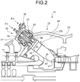
- Fig. 2 is a schematic diagram of the combustor and a combustor casing of the gas turbine shown in Fig. 1 .
- a gas turbine 1 shown in Fig. 1 includes a compressor 11, a combustor (a gas turbine combustor) 12, a turbine 13, and an exhaust chamber 14.
- a power generator is connected to the turbine 13, and the gas turbine 1 drives the power generator to generate power.
- the compressor 11 includes an air inlet 15 that takes in air, and a row of compressor vanes 17 and a row of compressor rotor blades 18 are alternatively arranged in a compressor casing 16.
- the combustor 12 is attached to a combustor casing 27 to supply fuel to compressed air compressed by the compressor 11, and the fuel is ignited by a burner and burned.
- a row of turbine nozzles 21 and a row of turbine rotor blades 22 are alternatively arranged in a turbine casing 20.
- the exhaust chamber 14 includes an exhaust diffuser 23 continuous to the turbine 13.
- a rotor (a turbine shaft) 24 is arranged to penetrate a central part of the compressor 11, the combustor 12, the turbine 13, and the exhaust chamber 14, and an end thereof on the compressor 11 side is rotatably supported by a bearing 25, with an end on the exhaust chamber 14 side being rotatably supported by a bearing 26.
- a plurality of disk plates are fixed to the rotor 24, and the row of compressor rotor blades 18 and the row of turbine rotor blades 22 are connected to the rotor 24.
- a drive shaft of the power generator is connected to the end of the rotor 24 on the exhaust chamber 14 side.
- the air taken in from the air inlet 15 of the compressor 11 passes through the row of compressor vanes 17 and the row of compressor rotor blades 18 and is compressed, to become high-temperature and high-pressure compressed air.
- the fuel supplied to the compressed air generated by the compressor 11 burns.
- High-temperature and high-pressure combustion gas which is a working fluid generated by the combustor 12, drives and rotates the rotor 24 in a process of passing through the row of turbine nozzles 21 and the row of turbine rotor blades 22 constituting the turbine 13.
- the power generator connected to the rotor 24 is driven to generate power, while flue gas passes through the exhaust diffuser 23 in the exhaust chamber 14 and is released into the atmosphere.
- the combustor 12 is constituted by connecting a combustor transition piece 33 to a nozzle block 30, and the combustor 12 is attached to the combustor casing 27.
- the nozzle block 30 includes a combustor outer casing 31, a combustor inner cylinder 32, a pilot nozzle 34, a premix nozzle 35, and a top hat nozzle 37.
- the combustor inner cylinder 32 is supported with a predetermined gap in the combustor outer casing 31 constituting the nozzle block 30, and the combustor transition piece 33 is connected to an end of the combustor inner cylinder 32.
- the pilot nozzle 34 is arranged in a central part of inside of the combustor inner cylinder 32, and a plurality of main fuel nozzles (the premix nozzles) 35 are arranged along a circumferential direction on an inner circumference of the combustor inner cylinder 32 to surround the pilot nozzle 34.
- a pilot cone 36 is attached to an end of the pilot nozzle 34.
- a plurality of top hat nozzles 37 are provided along a circumferential direction on an inner circumference of the combustor outer casing 31.
- the pilot nozzle 34 burns fuel, more specifically, pilot fuel Fp together with air to generate combustion gas, and supplies the combustion gas to the turbine 13 shown in Fig. 1 .
- the premix nozzle 35 burns fuel, more specifically, main fuel Fm together with air to generate combustion gas, and supplies the combustion gas to the turbine 13 shown in Fig. 1 .
- the combustor transition piece 33 is a cylindrical structure, and is arranged in inside 27I of the combustor casing 27 (inside of the combustor casing).
- a combustor-transition-piece guiding part 40 used at the time of attaching the combustor transition piece 33 to the combustor casing 27 or detaching the combustor transition piece 33 from the combustor casing 27 is provided on an outer circumference of the combustor transition piece 33.
- a guide jig support 41 that supports a combustor-transition-piece guide jig used at the time of attaching the combustor transition piece 33 to the gas turbine 1 shown in Fig.
- detaching the combustor transition piece 33 from the gas turbine 1 and detaching the combustor transition piece 33 from the combustor casing 27 are referred to as the same meaning.
- attaching the combustor transition piece 33 to the gas turbine 1 and attaching the combustor transition piece 33 to the combustor casing 27 are referred to as the same meaning.
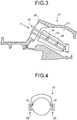
- Fig. 3 depicts a relation between the combustor-transition-piece guide jig and the combustor transition piece according to the present embodiment.
- Fig. 4 depicts the combustor transition piece inside of the combustor casing, as viewed from a direction of an arrow A in Fig. 3 .
- the combustor transition piece 33 in the inside 27I of the combustor casing is detached from the combustor casing 27 (that is, detached from the gas turbine 1 in Fig. 1 ), or when the combustor transition piece 33 is attached to the combustor casing 27 (that is, attached to the gas turbine 1 in Fig.
- the combustor transition piece 33 is guided by using a combustor-transition-piece guide jig 50 according to the present embodiment.
- the combustor-transition-piece guide jig 50 is attached to a combustor attachment port 28.
- the combustor-transition-piece guiding part 40 provided on the outer circumference of the combustor transition piece 33 is supported to support the combustor transition piece 33 itself, and a movement of the combustor transition piece 33 is guided.
- Fig. 5 is a flowchart of a procedure in the method of detaching a combustor of a gas turbine according to the present embodiment.
- Figs. 6 to 14 are explanatory diagrams of the procedure in the method of detaching a combustor of a gas turbine according to the present embodiment.
- the method of detaching a combustor of a gas turbine (hereinafter, "combustor detaching method") according to the present embodiment is performed by workers by using existing maintenance/inspection facilities installed in a plant or the like where the gas turbine 1 shown in Fig. 1 is installed.
- Step S101 the nozzle block 30 is detached from the combustor casing 27. Because the nozzle block 30 includes the pilot nozzle 34 and the premix nozzle 35 that burn fuel together with air to generate the combustion gas, detachment of the nozzle block 30 from the combustor casing 27 means detachment of a nozzle that burns fuel together with air to generate the combustion gas from the combustor casing 27.
- Step S102 When the nozzle block 30 is detached from the combustor casing 27, control proceeds to Step S102, and as shown in Fig. 7 , the combustor-transition-piece guide jig 50 is inserted from the combustor attachment port 28 formed in the combustor casing 27 toward the inside 27I of the combustor casing (in a direction shown by an arrow I in Fig. 7 ).
- the combustor attachment port 28 is provided for attaching the combustor 12 to the combustor casing 27.
- the combustor-transition-piece guide jig 50 includes two rails 51 and 52, a fixing member 53 attached to one ends of the two rails 51 and 52, and a holding member 54 attached to other ends of the two rails 51 and 52 opposite to the ends attached to the fixing member 53, and on the same side of the two rails.
- Fig. 9 depicts the combustor-transition-piece guide jig 50 as viewed from a direction shown by an arrow A in Fig. 8 .
- a combustor-casing side support 56 supported by the guide jig support 41 is formed on the holding member 54 on the opposite side of the fixing member 53.
- the two rails 51 and 52 are attached to the fixing member 53 so that a longitudinal direction thereof is orthogonal to a plate surface of the fixing member 53.
- the fixing member 53 is a plate-like member, and fastened and fixed to the combustor attachment port 28, for example, by a bolt, thereby fixing the two rails 51 and 52 to the combustor attachment port 28.
- the two rails 51 and 52 are supported by the guide jig support 41 in the inside 27I of the combustor casing by the holding member 54 attached to the ends thereof opposite to the ends attached to the fixing member 53.
- the combustor-transition-piece guide jig 50 is inserted into the inside of the combustor casing 27.
- the bolt is penetrated through a plurality of through holes 55 provided on the fixing member 53 shown in Fig. 9 , to fix the fixing member 53 to the combustor attachment port 28 by using bolt holes 29 for combustor attachment provided in a combustor casing flange 27F shown in Figs. 10-1 and 10-2 .
- the nozzle block 30 shown in Fig. 6 is fixed to the bolt holes 29 for combustor attachment by the bolts, to attach the combustor 12 to the combustor casing 27.
- the combustor-transition-piece guide jig 50 When the combustor-transition-piece guide jig 50 is inserted into the inside 27I of the combustor casing, as shown in Figs. 10-1 and 10-2 , the two rails 51 and 52 constituting the combustor-transition-piece guide jig 50 are supported by the combustor attachment port 28 and the guide jig support 41 via the fixing member 53 and the holding member 54. Therefore, the combustor-transition-piece guide jig 50 is supported at two positions, that is, the combustor attachment port 28 and the guide jig support 41.
- the combustor-transition-piece guiding part 40 provided on the outer circumference of the combustor transition piece 33 is put between the two rails 51 and 52 constituting the combustor-transition-piece guide jig 50.
- the combustor-transition-piece guiding part 40 comes into contact with at least one of the two rails 51 and 52, and moves along the two rails 51 and 52.
- the two rails 51 and 52 are arranged with the longitudinal direction thereof (a moving direction of the combustor transition piece 33 at the time of detaching or attaching the combustor transition piece 33) being parallel with a penetration direction of the combustor attachment port 28 (that is, an axis Zh of the combustor attachment port 28).
- a moving direction of the combustor transition piece 33 at the time of detaching or attaching the combustor transition piece 33 and the penetration direction of the combustor attachment port 28 become parallel with each other, an opening of the combustor attachment port 28 can be used efficiently when the combustor transition piece 33 passes through the combustor attachment port 28.
- an opening area of the combustor attachment port 28 can be requisite minimum, and thus the combustor attachment port 28 does not need to be enlarged more than necessary, and the strength of the casing constituting the combustor casing can be easily ensured.
- the combustor transition piece 33 is supported by a pair of combustor-transition-piece guide jigs 50 arranged opposite to each other. Therefore, the combustor-transition-piece guiding part 40 is also provided in a pair opposite to the combustor transition piece 33.
- At least one combustor-transition-piece guide jig 50 needs only to be arranged in a mode for supporting the mass of the combustor transition piece 33, and the number and arrangement of the combustor-transition-piece guide jig 50 and the combustor-transition-piece guiding part 40 are not limited to the mode disclosed in the present embodiment.
- the combustor transition piece 33 can be guided by one combustor-transition-piece guide jig 50, or by three or more combustor-transition-piece guide jigs 50. If a plurality of combustor-transition-piece guiding parts 40 are provided, a movement of the combustor transition piece 33 is stabilized at the time of attachment/detachment of the combustor transition piece 33. A stable movement of the combustor transition piece 33 can reduce a possibility of contact between the combustor transition piece 33 and other parts of the gas turbine in the inside 27I of the combustor casing.
- the number of the rails constituting the combustor-transition-piece guide jig 50 is not limited to two, and can be arranged in such a mode that at least one rail supports the mass of the combustor transition piece 33.
- the mode can be such that one rail constitutes the combustor-transition-piece guide jig 50, the combustor-transition-piece guide jig 50 is arranged on a vertical direction side of the combustor transition piece 33 (on an acting direction side of gravity), and one combustor-transition-piece guiding part 40 provided on the outer circumference of the combustor transition piece 33 is supported by the rail.
- the rails 51 and 52 are linear structures; however, for example, these can be curved structures according to a curved portion of the combustor transition piece 33.
- Step S102 when the combustor-transition-piece guide jig 50 is inserted toward the inside 27I of the combustor casing, control proceeds to Step S103.
- Step S103 by attaching the fixing member 53 of the combustor-transition-piece guide jig 50 to the combustor attachment port 28, the combustor-transition-piece guide jig 50 is attached to the combustor attachment port 28.
- Step S104 Control proceeds to Step S104, and as shown in Figs. 10-1 and 13 , the combustor transition piece 33 is moved in a direction away from the inside 27I of the combustor casing (a direction indicated by an arrow E in Figs. 10-1 and 13 ), and the combustor transition piece 33 is detached from the combustor casing 27.
- the combustor-transition-piece guiding part 40 provided on the combustor transition piece 33 comes into contact with at least one of the two rails 51 and 52 constituting the combustor-transition-piece guide jig 50, and engages therewith.
- the combustor transition piece 33 is supported by at least one of the two rails 51 and 52 constituting the combustor-transition-piece guide jig 50, and moves along the two rails 51 and 52.
- the both may come into contact with each other at the time of detaching the combustor transition piece 33 from the combustor casing 27.
- the moving direction of the combustor transition piece 33 is defined in one direction (in the penetration direction of the combustor attachment port 28 according to the present embodiment) by the combustor-transition-piece guide jig 50, the possibility of contact between the combustor transition piece 33 and the combustor attachment port 28 can be avoided.
- the combustor attachment port 28 has such a shape that different circles C1 and C2 respectively having a center CC1 and a center CC2 different from each other are overlapped on each other.
- the centers CC1 and CC2 are present on a plane P including a rotation axis Zr of the turbine 13 and the compressor 11 of the gas turbine 1, and on an attachment plane of the nozzle block (see Fig. 2 ) to the combustor casing flange 27F (see Fig. 11 ). Further, diameters of the circles C1 and C2 can be the same or different.
- the combustor attachment port 28 is provided in a plurality of numbers toward a circumferential direction of the combustor casing 27.
- the combustor attachment port 28 has a shape in which different circles C1 and C2 having the centers CC1 and CC2 different from each other are overlapped on each other, if two holes are bored by a boring tool, designating CC1 and CC2 as boring centers, the combustor attachment port 28 can be easily formed without using an end mill.
- the shape of a combustor attachment port 28a shown in Fig. 12 is a shape of a racetrack, that is, a shape in which two semicircular arcs are connected by two straight lines.
- centers of the respective semicircular arcs are CC1 and CC2.
- the centers CC1 and CC2 are present on the plane P including a rotation axis Zr of the turbine 13 and the compressor 11 of the gas turbine 1, and on the attachment plane of the nozzle block (see Fig. 2 ) to the combustor casing flange 27F (see Fig. 12 ).
- the shape of the combustor attachment port 28 is not limited to the shapes described above, and can be a polygonal shape such as elliptic, square, hexagonal, or octagonal.
- the combustor attachment port 28 needs only to be formed in an opening that is long in a radial direction, centering on the rotation shaft Zr, and short in a circumferential direction.
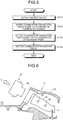
- Fig. 15 is a flowchart of a procedure in a method of attaching a combustor of a gas turbine according to the present embodiment.
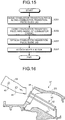
- Figs. 16 to 20 are explanatory diagrams of the procedure in the method of attaching a combustor of a gas turbine according to the present embodiment.
- the method of attaching a combustor of a gas turbine (hereinafter, "combustor attaching method") according to the present embodiment is performed by workers by using existing maintenance/inspection facilities installed in a plant or the like where the gas turbine 1 shown in Fig. 1 is installed.
- the combustor-transition-piece guide jig 50 is in a state of being attached to the combustor attachment port 28 of the combustor casing 27.
- the combustor attaching method is performed, at Step S201, as shown in Fig. 16 , the combustor-transition-piece guiding part 40 provided in the combustor transition piece 33 is inserted into between the two rails 51 and 52 constituting the combustor-transition-piece guide jig 50, so that the combustor transition piece 33 is inserted into the combustor-transition-piece guide jig 50.
- the combustor transition piece 33 is moved in a direction shown by an arrow I shown in Fig. 16 , that is, toward the combustor attachment port 28.
- Step S202 control proceeds to Step S202 where the combustor transition piece 33 is carried into the inside 27I of the combustor casing along the combustor-transition-piece guide jig 50.
- the combustor-transition-piece guiding part 40 provided on the outer circumference of the combustor transition piece 33 is then sandwiched between the two rails 51 and 52 constituting the combustor-transition-piece guide jig 50.
- the combustor-transition-piece guiding part 40 provided in the combustor transition piece 33 comes into contact with at least one of the two rails 51 and 52 constituting the combustor-transition-piece guide jig 50, and engages therewith. Consequently, as shown in Fig. 17 , the combustor transition piece 33 is supported by at least one of the two rails 51 and 52 constituting the combustor-transition-piece guide jig 50 via the combustor-transition-piece guiding part 40 during its movement, and moves along the two rails 51 and 52.
- Step S203 When the combustor transition piece 33 is carried to the inside 27I of the combustor casing and arranged at a specified position, the combustor transition piece 33 is fixed to a transition-piece fixing unit in the inside 27I of the combustor casing. Thereafter, control proceeds to Step S203, and as shown in Fig. 18 , the combustor-transition-piece guide jig 50 is detached from the combustor casing 27. At this time, the combustor-transition-piece guide jig 50 is pulled out in a direction away from the combustor attachment port 28 (a direction shown by an arrow E in Fig. 18 ), and extracted from the inside 27I of the combustor casing.
- Step S204 control proceeds to Step S204 and the nozzle block 30 is attached to the combustor attachment port 28 of the combustor casing 27.
- Step S204 an end of the combustor inner cylinder 32 constituting the nozzle block 30 is inserted into the combustor transition piece 33. With this configuration, the combustor 12 is attached to the combustor casing 27.
- the combustor-transition-piece guiding part provided on the combustor transition piece is supported by the rails attached to the combustor casing.
- a large-scale exchanging facility is not required at the time of detaching or attaching the combustor from or to the gas turbine.
- the combustor transition piece is supported by the rails via the combustor-transition-piece guiding part, a force at the time of moving the combustor transition piece from the combustor casing or at the time of moving the combustor transition piece to the combustor casing is reduced.
- the load on workers can be reduced due to a simple configuration. Furthermore, because the load on workers is reduced, the time required for detaching or attaching the combustor can be reduced. Therefore, the time required for maintenance and inspection of the gas turbine can be reduced and a down time of the gas turbine can be reduced.
- the combustor-transition-piece guide jig, the method of detaching a combustor of a gas turbine, and the method of attaching a combustor of a gas turbine according to the present invention are useful at the time of detaching or attaching a combustor of a gas turbine from or to the gas turbine, and are particularly suitable for reducing workload at the time of moving a combustor transition piece.
Landscapes
- Engineering & Computer Science (AREA)
- Mechanical Engineering (AREA)
- General Engineering & Computer Science (AREA)
- Chemical & Material Sciences (AREA)
- Combustion & Propulsion (AREA)
- Turbine Rotor Nozzle Sealing (AREA)
- Combustion Of Fluid Fuel (AREA)
Description
- The present invention relates to detachment or attachment of a combustor of a gas turbine from or to the gas turbine.
- A gas turbine is constituted by a compressor, a combustor, and a turbine. Periodic inspections are required for the gas turbine to demonstrate its stable performance. Further, when parts constituting the combustor are consumed due to operations of the gas turbine, replacement and maintenance are required. Because the combustor is large in mass, the load on workers at the time of inspection increases. Further, the time required for the inspection becomes long. If a long time is required for the inspection, its operation time decreases, and therefore there is a demand to finish the inspection as quickly as possible. Accordingly, as for cases when the combustor is detached from the gas turbine for inspections and maintenance, for example, there are disclosed techniques for detaching and attaching a combustor from and to a gas turbine by using a combustor exchanger in Patent Documents 1 to 5.
-
- Patent Document 1: Japanese Patent Application Laid-open No.
H9-168931 - Patent Document 2: Japanese Patent Application Laid-open No.
H9-210361 - Patent Document 3: Japanese Patent Application Laid-open No.
H9-108961 - Patent Document 4: Japanese Patent Application Laid-open No.
H10-196959 - Patent Document 5: Japanese Patent Application Laid-open No.
H9-79577 -
US 3991562 A discloses a structure of a combustor assembly where an inner center liner is provided on an integral guide structure that allows the inner center liner to be replaced without disassembling the remaining portions of the combustor assembly including a transition duct connecting the outer liner to the turbine inlet. -
US 2778192 A also discloses an integral combustor basket structure in which the individual combustion chamber elements are arranged to permit free radial and axial expansion along a number of parallel rails of a framework in operation of the gas turbine. The structure of the basket would have to be removed from the turbine in its entirety and the frame structure (44) is an integral part of the combustor assembly. -
JP H082106462 A - The techniques disclosed in Patent Documents 1 to 3 use a combustor exchanger, and thus a device required for detaching and attaching the combustor becomes complicated and large, thereby increasing the cost for introducing such a device. Therefore, there has been desired a method that can realize detachment and attachment of a combustor with a simple configuration, while reducing the load on workers. The present invention has been achieved to solve the above circumstances, and an object of the present invention is to reduce the load on workers due to a simple configuration at least at the time of detaching a combustor of a gas turbine from the gas turbine or at the time of attaching the combustor of the gas turbine to the gas turbine.
- To solve the problem the invention provides a combustor-transition-piece guide jig according to claim 1, a method of detaching a combustor of a gas turbine from the gas turbine according to claim 4 and a method of attaching a combustor of a gas turbine to the gas turbine according to
claim 5. According to an aspect of the present invention, a combustor-transition-piece guide jig to be used at a time of attaching to the gas turbine or detaching from the gas turbine a combustor including a nozzle block that burns fuel together with air to generate combustion gas and a combustor transition piece that connects the nozzle block with a turbine of a gas turbine to guide the combustion gas to the turbine, includes: a rail that is inserted from a combustor attachment port formed in a combustor casing of the gas turbine for attaching the combustor toward inside of the combustor casing, comes into contact with a combustor-transition-piece guiding part provided on the combustor transition piece, and guides the combustor transition piece; and a fixing member that is provided at one end of the rail, is attached to the combustor attachment port, and fixes the rail to the combustor attachment port. - In this way, by supporting the combustor-transition-piece guiding part provided on the combustor transition piece by the rail attached to the combustor casing, a large-scale exchanging facility is not required at the time of detaching or attaching the combustor from or to the gas turbine. Because the combustor transition piece is supported by the rail via the combustor-transition-piece guiding part, a force at the time of moving the combustor transition piece from the combustor casing or at the time of moving the combustor transition piece to the combustor casing is reduced. The rail reaches inside of the combustor casing, and thus the combustor transition piece can be moved stably. As a result, the load on workers can be reduced due to a simple configuration, at least at the time of detaching the combustor of the gas turbine from the gas turbine or at the time of attaching the combustor of the gas turbine to the gas turbine.
- Advantageously, in the combustor-transition-piece guide jig, the rail is parallel with a penetration direction of the combustor attachment port. Accordingly, if the size of an external shape of the combustor transition piece is the same, an opening of the combustor attachment port can be requisite minimum. Therefore, the combustor attachment port does not need to be enlarged more than necessary, and the strength of a casing constituting the combustor casing can be easily ensured.
- According to another aspect of the present invention, a method of detaching a combustor of a gas turbine, at a time of detaching a combustor that includes a nozzle block that burns fuel together with air to generate combustion gas and a combustor transition piece that connects the nozzle block with a turbine of a gas turbine to guide the combustion gas to the turbine, and is attached to a combustor casing of the gas turbine, includes: a step of detaching the nozzle block from the combustor casing; a step of inserting a combustor-transition-piece guide jig for guiding the combustor transition piece from a combustor attachment port formed in the combustor casing for attaching the combustor toward inside of the combustor casing; a step of attaching the combustor-transition-piece guide jig to the combustor attachment port; and a step of extracting the combustor transition piece from the combustor attachment port, while causing a combustor-transition-piece guiding part provided on the combustor transition piece to engage with the combustor-transition-piece guide jig to move along the combustor-transition-piece guide jig.
- In this way, by supporting the combustor-transition-piece guiding part provided on the combustor transition piece by the rail attached to the combustor casing, a large-scale exchanging facility is not required at the time of detaching the combustor from the gas turbine. Because the combustor transition piece is supported by the rail via the combustor-transition-piece guiding part, and movement thereof is guided in one direction (a longitudinal direction of the rail), a force at the time of detaching the combustor transition piece from the combustor casing is reduced. As a result, at the time of detaching the combustor of the gas turbine from the gas turbine, the load on workers can be reduced due to a simple configuration.
- According to still another aspect of the present invention, a method of attaching a combustor of a gas turbine, at a time of attaching a combustor including a nozzle block that burns fuel together with air to generate combustion gas and a combustor transition piece that connects the nozzle block with a turbine of a gas turbine to guide the combustion gas to the turbine to the gas turbine, includes: a step of bringing a combustor-transition-piece guiding part provided on the combustor transition piece to engage with the combustor-transition-piece guide jig into contact with a combustor-transition-piece guide jig that guides the combustor transition piece, which is attached to a combustor attachment port formed in a combustor casing of the gas turbine for attaching the combustor; a step of carrying the combustor transition piece from the combustor attachment port to inside of the combustor casing, while moving the combustor-transition-piece guiding part along the combustor-transition-piece guide jig; a step of detaching the combustor-transition-piece guide jig from the combustor attachment port; and a step of attaching the nozzle block to the combustor attachment port.
- In this way, by supporting the combustor-transition-piece guiding part provided on the combustor transition piece by the rail attached to the combustor casing, a large-scale exchanging facility is not required at the time of attaching the combustor to the gas turbine. Because the combustor transition piece is supported by the rail via the combustor-transition-piece guiding part, a force at the time of moving the combustor transition piece toward the combustor casing is reduced. As a result, at the time of attaching the combustor of the gas turbine to the gas turbine, the load on workers can be reduced due to a simple configuration.
- According to the present invention, at least at the time of detaching the combustor of the gas turbine from the gas turbine or at the time of attaching the combustor of the gas turbine to the gas turbine, the load on workers can be reduced due to a simple configuration.
-
- [
Fig. 1] Fig. 1 is a schematic diagram of a gas turbine, to which a method of attaching and detaching a combustor of a gas turbine according to an embodiment of the present invention can be applied. - [
Fig. 2] Fig. 2 is a schematic diagram of a combustor and a combustor casing of the gas turbine shown inFig. 1 . - [
Fig. 3] Fig. 3 depicts a relation between a combustor-transition-piece guide jig and a combustor transition piece according to the embodiment. - [
Fig. 4] Fig. 4 depicts a combustor transition piece inside of a combustor casing, as viewed from a direction of an arrow A inFig. 3 . - [
Fig. 5] Fig. 5 is a flowchart of a procedure in a method of detaching a combustor of a gas turbine according to the embodiment. - [
Fig. 6] Fig. 6 is an explanatory diagram of a procedure of detaching a nozzle block in the method of detaching a combustor of a gas turbine according to the embodiment. - [
Fig. 7] Fig. 7 is an explanatory diagram of a procedure of attaching a combustor-transition-piece guide jig in the method of detaching a combustor of a gas turbine according to the embodiment. - [
Fig. 8] Fig. 8 is a front view of a combustor-transition-piece guide jig according to the embodiment. - [
Fig. 9] Fig. 9 is a side view of a fixing member of the combustor-transition-piece guide jig according to the embodiment. - [
Fig. 10-1] Fig. 10-1 is a partial cross-sectional view of inside of a combustor casing of the gas turbine according to the embodiment. - [
Fig. 10-2] Fig. 10-2 is a front view of the combustor casing of the gas turbine according to the embodiment, as viewed from a combustor attachment port side. - [
Fig. 11] Fig. 11 depicts an opening shape of a combustor attachment port of the combustor of the gas turbine according to the embodiment. - [
Fig. 12] Fig. 12 depicts an opening shape of the combustor attachment port of the combustor of the gas turbine according to the embodiment. - [
Fig. 13] Fig. 13 is an explanatory diagram of a procedure of detaching a combustor transition piece in the method of detaching a combustor of a gas turbine according to the embodiment. - [
Fig. 14] Fig. 14 depicts a state where the combustor transition piece is detached in the method of detaching a combustor of a gas turbine according to the embodiment. - [
Fig. 15] Fig. 15 is a flowchart of a procedure in a method of attaching a combustor of a gas turbine according to the embodiment. - [
Fig. 16] Fig. 16 depicts a state before the combustor transition piece is attached in the method of attaching a combustor of a gas turbine according to the embodiment. - [
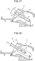
Fig. 17] Fig. 17 is an explanatory diagram of a procedure of carrying the combustor transition piece into a casing in the method of attaching a combustor of a gas turbine according to the embodiment. - [
Fig. 18] Fig. 18 is an explanatory diagram of a procedure of detaching the combustor-transition-piece guide jig in the method of attaching a combustor of a gas turbine according to the embodiment. - [
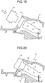
Fig. 19] Fig. 19 is an explanatory diagram of a procedure of attaching the nozzle block in the method of attaching a combustor of a gas turbine according to the embodiment. - [
Fig. 20] Fig. 20 depicts a state after the nozzle block is attached in the method of attaching a combustor of a gas turbine according to the embodiment. -
- 1
- gas turbine
- 11
- compressor
- 12
- combustor
- 13
- turbine
- 14
- exhaust chamber
- 16
- compressor casing
- 20
- turbine casing
- 24
- rotor
- 25, 26
- bearing
- 27
- combustor casing
- 27F
- combustor casing flange
- 27I
- inside of combustor casing (inside)
- 28, 28a
- combustor attachment port
- 30
- nozzle block
- 31
- combustor outer casing
- 32
- combustor inner cylinder
- 33
- combustor transition piece
- 34
- pilot nozzle
- 35
- premix nozzle
- 40
- combustor-transition-piece guiding part
- 41
- guide jig support
- 50
- combustor-transition-piece guide jig
- 51, 52
- rail
- 53
- fixing member
- 54
- holding member
- 56
- combustor-casing side support
- Exemplary embodiments of the present invention will be explained below in detail with reference to the accompanying drawings. The present invention is not limited to the following descriptions. In addition, constituent elements in the following descriptions include those that can be easily assumed by those skilled in the art or that are substantially equivalent.
-
Fig. 1 is a schematic diagram of a gas turbine, to which a method of attaching and detaching a combustor of a gas turbine according to an embodiment of the present invention can be applied.Fig. 2 is a schematic diagram of the combustor and a combustor casing of the gas turbine shown inFig. 1 . A gas turbine 1 shown inFig. 1 includes acompressor 11, a combustor (a gas turbine combustor) 12, aturbine 13, and anexhaust chamber 14. For example, a power generator is connected to theturbine 13, and the gas turbine 1 drives the power generator to generate power. - The
compressor 11 includes anair inlet 15 that takes in air, and a row ofcompressor vanes 17 and a row ofcompressor rotor blades 18 are alternatively arranged in acompressor casing 16. Thecombustor 12 is attached to acombustor casing 27 to supply fuel to compressed air compressed by thecompressor 11, and the fuel is ignited by a burner and burned. In theturbine 13, a row ofturbine nozzles 21 and a row ofturbine rotor blades 22 are alternatively arranged in aturbine casing 20. - The
exhaust chamber 14 includes anexhaust diffuser 23 continuous to theturbine 13. A rotor (a turbine shaft) 24 is arranged to penetrate a central part of thecompressor 11, thecombustor 12, theturbine 13, and theexhaust chamber 14, and an end thereof on thecompressor 11 side is rotatably supported by abearing 25, with an end on theexhaust chamber 14 side being rotatably supported by abearing 26. A plurality of disk plates are fixed to therotor 24, and the row ofcompressor rotor blades 18 and the row ofturbine rotor blades 22 are connected to therotor 24. A drive shaft of the power generator is connected to the end of therotor 24 on theexhaust chamber 14 side. - The air taken in from the
air inlet 15 of thecompressor 11 passes through the row ofcompressor vanes 17 and the row ofcompressor rotor blades 18 and is compressed, to become high-temperature and high-pressure compressed air. In thecombustor 12, the fuel supplied to the compressed air generated by thecompressor 11 burns. High-temperature and high-pressure combustion gas, which is a working fluid generated by thecombustor 12, drives and rotates therotor 24 in a process of passing through the row ofturbine nozzles 21 and the row ofturbine rotor blades 22 constituting theturbine 13. With this configuration, the power generator connected to therotor 24 is driven to generate power, while flue gas passes through theexhaust diffuser 23 in theexhaust chamber 14 and is released into the atmosphere. - As shown in
Fig. 2 , thecombustor 12 is constituted by connecting acombustor transition piece 33 to anozzle block 30, and thecombustor 12 is attached to thecombustor casing 27. Thenozzle block 30 includes a combustorouter casing 31, a combustorinner cylinder 32, apilot nozzle 34, apremix nozzle 35, and atop hat nozzle 37. - The combustor
inner cylinder 32 is supported with a predetermined gap in the combustorouter casing 31 constituting thenozzle block 30, and thecombustor transition piece 33 is connected to an end of the combustorinner cylinder 32. Thepilot nozzle 34 is arranged in a central part of inside of the combustorinner cylinder 32, and a plurality of main fuel nozzles (the premix nozzles) 35 are arranged along a circumferential direction on an inner circumference of the combustorinner cylinder 32 to surround thepilot nozzle 34. Apilot cone 36 is attached to an end of thepilot nozzle 34. A plurality oftop hat nozzles 37 are provided along a circumferential direction on an inner circumference of the combustorouter casing 31. - The
pilot nozzle 34 burns fuel, more specifically, pilot fuel Fp together with air to generate combustion gas, and supplies the combustion gas to theturbine 13 shown inFig. 1 . Thepremix nozzle 35 burns fuel, more specifically, main fuel Fm together with air to generate combustion gas, and supplies the combustion gas to theturbine 13 shown inFig. 1 . - The
combustor transition piece 33 is a cylindrical structure, and is arranged in inside 27I of the combustor casing 27 (inside of the combustor casing). A combustor-transition-piece guiding part 40 used at the time of attaching thecombustor transition piece 33 to thecombustor casing 27 or detaching thecombustor transition piece 33 from thecombustor casing 27 is provided on an outer circumference of thecombustor transition piece 33. Aguide jig support 41 that supports a combustor-transition-piece guide jig used at the time of attaching thecombustor transition piece 33 to the gas turbine 1 shown inFig. 1 (more specifically, to the combustor casing 27) or detaching thecombustor transition piece 33 from the gas turbine 1 (more specifically, from the combustor casing 27) is provided in the inside 27I of the combustor casing. Hereinafter, detaching thecombustor transition piece 33 from the gas turbine 1 and detaching thecombustor transition piece 33 from thecombustor casing 27 are referred to as the same meaning. Further, attaching thecombustor transition piece 33 to the gas turbine 1 and attaching thecombustor transition piece 33 to thecombustor casing 27 are referred to as the same meaning. -
Fig. 3 depicts a relation between the combustor-transition-piece guide jig and the combustor transition piece according to the present embodiment.Fig. 4 depicts the combustor transition piece inside of the combustor casing, as viewed from a direction of an arrow A inFig. 3 . As shown inFigs. 3 and 4 , when thecombustor transition piece 33 in the inside 27I of the combustor casing is detached from the combustor casing 27 (that is, detached from the gas turbine 1 inFig. 1 ), or when thecombustor transition piece 33 is attached to the combustor casing 27 (that is, attached to the gas turbine 1 inFig. 1 ), thecombustor transition piece 33 is guided by using a combustor-transition-piece guide jig 50 according to the present embodiment. As shown inFig. 3 , the combustor-transition-piece guide jig 50 is attached to acombustor attachment port 28. At the time of detaching or attaching thecombustor transition piece 33, the combustor-transition-piece guiding part 40 provided on the outer circumference of thecombustor transition piece 33 is supported to support thecombustor transition piece 33 itself, and a movement of thecombustor transition piece 33 is guided. -
Fig. 5 is a flowchart of a procedure in the method of detaching a combustor of a gas turbine according to the present embodiment.Figs. 6 to 14 are explanatory diagrams of the procedure in the method of detaching a combustor of a gas turbine according to the present embodiment. The method of detaching a combustor of a gas turbine (hereinafter, "combustor detaching method") according to the present embodiment is performed by workers by using existing maintenance/inspection facilities installed in a plant or the like where the gas turbine 1 shown inFig. 1 is installed. - When the combustor detaching method is performed, at Step S101, as shown in
Fig. 6 , thenozzle block 30 is detached from thecombustor casing 27. Because thenozzle block 30 includes thepilot nozzle 34 and thepremix nozzle 35 that burn fuel together with air to generate the combustion gas, detachment of thenozzle block 30 from thecombustor casing 27 means detachment of a nozzle that burns fuel together with air to generate the combustion gas from thecombustor casing 27. - When the
nozzle block 30 is detached from thecombustor casing 27, control proceeds to Step S102, and as shown inFig. 7 , the combustor-transition-piece guide jig 50 is inserted from thecombustor attachment port 28 formed in thecombustor casing 27 toward the inside 27I of the combustor casing (in a direction shown by an arrow I inFig. 7 ). Thecombustor attachment port 28 is provided for attaching thecombustor 12 to thecombustor casing 27. - As shown in
Figs. 8 and9 , the combustor-transition-piece guide jig 50 includes tworails member 53 attached to one ends of the tworails member 54 attached to other ends of the tworails member 53, and on the same side of the two rails.Fig. 9 depicts the combustor-transition-piece guide jig 50 as viewed from a direction shown by an arrow A inFig. 8 . A combustor-casing side support 56 supported by theguide jig support 41 is formed on the holdingmember 54 on the opposite side of the fixingmember 53. - The two
rails member 53 so that a longitudinal direction thereof is orthogonal to a plate surface of the fixingmember 53. The fixingmember 53 is a plate-like member, and fastened and fixed to thecombustor attachment port 28, for example, by a bolt, thereby fixing the tworails combustor attachment port 28. Further, the tworails guide jig support 41 in the inside 27I of the combustor casing by the holdingmember 54 attached to the ends thereof opposite to the ends attached to the fixingmember 53. Thus, the combustor-transition-piece guide jig 50 is inserted into the inside of thecombustor casing 27. - The bolt is penetrated through a plurality of through
holes 55 provided on the fixingmember 53 shown inFig. 9 , to fix the fixingmember 53 to thecombustor attachment port 28 by using bolt holes 29 for combustor attachment provided in acombustor casing flange 27F shown inFigs. 10-1 and10-2 . Thenozzle block 30 shown inFig. 6 is fixed to the bolt holes 29 for combustor attachment by the bolts, to attach thecombustor 12 to thecombustor casing 27. - When the combustor-transition-
piece guide jig 50 is inserted into the inside 27I of the combustor casing, as shown inFigs. 10-1 and10-2 , the tworails piece guide jig 50 are supported by thecombustor attachment port 28 and theguide jig support 41 via the fixingmember 53 and the holdingmember 54. Therefore, the combustor-transition-piece guide jig 50 is supported at two positions, that is, thecombustor attachment port 28 and theguide jig support 41. Thus, by supporting the combustor-transition-piece guide jig 50 at two positions, when thecombustor transition piece 33 is guided and moved by the combustor-transition-piece guide jig 50, deformation and deflection of the combustor-transition-piece guide jig 50 can be suppressed, and thecombustor transition piece 33 can be reliably guided into the inside of thecombustor casing 27. - As shown in
Fig. 9 , the combustor-transition-piece guiding part 40 provided on the outer circumference of thecombustor transition piece 33 is put between the tworails piece guide jig 50. With this configuration, when thecombustor transition piece 33 is detached from thecombustor casing 27 or attaching thecombustor transition piece 33 to thecombustor casing 27, the combustor-transition-piece guiding part 40 comes into contact with at least one of the tworails rails - The two
rails combustor transition piece 33 at the time of detaching or attaching the combustor transition piece 33) being parallel with a penetration direction of the combustor attachment port 28 (that is, an axis Zh of the combustor attachment port 28). With this configuration, because the moving direction of thecombustor transition piece 33 at the time of detaching or attaching thecombustor transition piece 33 and the penetration direction of thecombustor attachment port 28 become parallel with each other, an opening of thecombustor attachment port 28 can be used efficiently when thecombustor transition piece 33 passes through thecombustor attachment port 28. For example, if the size of an external shape of thecombustor transition piece 33 is the same, an opening area of thecombustor attachment port 28 can be requisite minimum, and thus thecombustor attachment port 28 does not need to be enlarged more than necessary, and the strength of the casing constituting the combustor casing can be easily ensured. - As shown in
Figs. 10-1 and10-2 , thecombustor transition piece 33 is supported by a pair of combustor-transition-piece guide jigs 50 arranged opposite to each other. Therefore, the combustor-transition-piece guiding part 40 is also provided in a pair opposite to thecombustor transition piece 33. At least one combustor-transition-piece guide jig 50 needs only to be arranged in a mode for supporting the mass of thecombustor transition piece 33, and the number and arrangement of the combustor-transition-piece guide jig 50 and the combustor-transition-piece guiding part 40 are not limited to the mode disclosed in the present embodiment. For example, thecombustor transition piece 33 can be guided by one combustor-transition-piece guide jig 50, or by three or more combustor-transition-piece guide jigs 50. If a plurality of combustor-transition-piece guiding parts 40 are provided, a movement of thecombustor transition piece 33 is stabilized at the time of attachment/detachment of thecombustor transition piece 33. A stable movement of thecombustor transition piece 33 can reduce a possibility of contact between thecombustor transition piece 33 and other parts of the gas turbine in the inside 27I of the combustor casing. - The number of the rails constituting the combustor-transition-
piece guide jig 50 is not limited to two, and can be arranged in such a mode that at least one rail supports the mass of thecombustor transition piece 33. For example, the mode can be such that one rail constitutes the combustor-transition-piece guide jig 50, the combustor-transition-piece guide jig 50 is arranged on a vertical direction side of the combustor transition piece 33 (on an acting direction side of gravity), and one combustor-transition-piece guiding part 40 provided on the outer circumference of thecombustor transition piece 33 is supported by the rail. Also in this case, because the mass of thecombustor transition piece 33 can be received by the combustor-transition-piece guide jig 50, the load on workers can be reduced. In the present embodiment, therails combustor transition piece 33. - At Step S102, when the combustor-transition-
piece guide jig 50 is inserted toward the inside 27I of the combustor casing, control proceeds to Step S103. At Step S103, by attaching the fixingmember 53 of the combustor-transition-piece guide jig 50 to thecombustor attachment port 28, the combustor-transition-piece guide jig 50 is attached to thecombustor attachment port 28. - Control proceeds to Step S104, and as shown in
Figs. 10-1 and13 , thecombustor transition piece 33 is moved in a direction away from the inside 27I of the combustor casing (a direction indicated by an arrow E inFigs. 10-1 and13 ), and thecombustor transition piece 33 is detached from thecombustor casing 27. At this time, the combustor-transition-piece guiding part 40 provided on thecombustor transition piece 33 comes into contact with at least one of the tworails piece guide jig 50, and engages therewith. With this configuration, as shown inFig. 13 , thecombustor transition piece 33 is supported by at least one of the tworails piece guide jig 50, and moves along the tworails - As described above, at the time of detaching the
combustor transition piece 33 from thecombustor casing 27, because a part of the mass of thecombustor transition piece 33 is supported by the combustor-transition-piece guide jig 50, the labor of workers at the time of moving thecombustor transition piece 33 from the inside 27I of the combustor casing is considerably reduced. Particularly, because the mass of thecombustor transition piece 33 becomes about 100 kilograms, a reduction effect of the labor of workers by using the combustor-transition-piece guide jig 50 is remarkable. - Further, because a gap between the
combustor attachment port 28 and thecombustor transition piece 33 shown inFig. 10-1 is limited, the both may come into contact with each other at the time of detaching thecombustor transition piece 33 from thecombustor casing 27. In the present embodiment; however, because the moving direction of thecombustor transition piece 33 is defined in one direction (in the penetration direction of thecombustor attachment port 28 according to the present embodiment) by the combustor-transition-piece guide jig 50, the possibility of contact between thecombustor transition piece 33 and thecombustor attachment port 28 can be avoided. With this configuration, the contact between thecombustor transition piece 33 and thecombustor attachment port 28 can be avoided only by pulling out thecombustor transition piece 33 from the inside 27I of the combustor casing, and thus workers do not need to pay attention to the contact between these. As a result, the load on workers can be further reduced. - Because the
combustor transition piece 33 includes a curved portion to be connected to theturbine 13 shown inFig. 1 , when thecombustor transition piece 33 is detached from thecombustor casing 27, an interference between thecombustor attachment port 28 and thecombustor transition piece 33 needs to be avoided. In the present embodiment, as shown inFig. 11 , thecombustor attachment port 28 has such a shape that different circles C1 and C2 respectively having a center CC1 and a center CC2 different from each other are overlapped on each other. The centers CC1 and CC2 are present on a plane P including a rotation axis Zr of theturbine 13 and thecompressor 11 of the gas turbine 1, and on an attachment plane of the nozzle block (seeFig. 2 ) to thecombustor casing flange 27F (seeFig. 11 ). Further, diameters of the circles C1 and C2 can be the same or different. - Consequently, the interference between the
combustor attachment port 28 and thecombustor transition piece 33 can be avoided. Further, thecombustor attachment port 28 is provided in a plurality of numbers toward a circumferential direction of thecombustor casing 27. By having such a configuration, a gap between the adjacentcombustor attachment ports 28 can be ensured, and a stress generated between the adjacentcombustor attachment ports 28 can be reduced. Further, because thecombustor attachment port 28 has a shape in which different circles C1 and C2 having the centers CC1 and CC2 different from each other are overlapped on each other, if two holes are bored by a boring tool, designating CC1 and CC2 as boring centers, thecombustor attachment port 28 can be easily formed without using an end mill. - The shape of a
combustor attachment port 28a shown inFig. 12 is a shape of a racetrack, that is, a shape in which two semicircular arcs are connected by two straight lines. In this case, centers of the respective semicircular arcs are CC1 and CC2. The centers CC1 and CC2 are present on the plane P including a rotation axis Zr of theturbine 13 and thecompressor 11 of the gas turbine 1, and on the attachment plane of the nozzle block (seeFig. 2 ) to thecombustor casing flange 27F (seeFig. 12 ). By having such a configuration, the same action and effect as those when the shape of thecombustor attachment port 28 is such that different circles C1 and C2 having the center CC1 and the center CC2 different from each other are overlapped on each other can be obtained. The shape of thecombustor attachment port 28 is not limited to the shapes described above, and can be a polygonal shape such as elliptic, square, hexagonal, or octagonal. Thecombustor attachment port 28 needs only to be formed in an opening that is long in a radial direction, centering on the rotation shaft Zr, and short in a circumferential direction. - As shown in
Fig. 14 , when thecombustor transition piece 33 is detached from thecombustor casing 27, the combustor-transition-piece guide jig 50 is left in the inside 27I of the combustor casing. A method of attaching a combustor of a gas turbine according to the present embodiment is explained next. -
Fig. 15 is a flowchart of a procedure in a method of attaching a combustor of a gas turbine according to the present embodiment.Figs. 16 to 20 are explanatory diagrams of the procedure in the method of attaching a combustor of a gas turbine according to the present embodiment. The method of attaching a combustor of a gas turbine (hereinafter, "combustor attaching method") according to the present embodiment is performed by workers by using existing maintenance/inspection facilities installed in a plant or the like where the gas turbine 1 shown inFig. 1 is installed. - When the combustor attaching method is performed, as shown in
Fig. 14 , the combustor-transition-piece guide jig 50 is in a state of being attached to thecombustor attachment port 28 of thecombustor casing 27. When the combustor attaching method is performed, at Step S201, as shown inFig. 16 , the combustor-transition-piece guiding part 40 provided in thecombustor transition piece 33 is inserted into between the tworails piece guide jig 50, so that thecombustor transition piece 33 is inserted into the combustor-transition-piece guide jig 50. At this time, thecombustor transition piece 33 is moved in a direction shown by an arrow I shown inFig. 16 , that is, toward thecombustor attachment port 28. - As shown in
Fig. 17 , control proceeds to Step S202 where thecombustor transition piece 33 is carried into the inside 27I of the combustor casing along the combustor-transition-piece guide jig 50. As shown inFig. 17 , the combustor-transition-piece guiding part 40 provided on the outer circumference of thecombustor transition piece 33 is then sandwiched between the tworails piece guide jig 50. - With this configuration, the combustor-transition-
piece guiding part 40 provided in thecombustor transition piece 33 comes into contact with at least one of the tworails piece guide jig 50, and engages therewith. Consequently, as shown inFig. 17 , thecombustor transition piece 33 is supported by at least one of the tworails piece guide jig 50 via the combustor-transition-piece guiding part 40 during its movement, and moves along the tworails - In this way, when the
combustor transition piece 33 is attached to thecombustor casing 27, because a part of the mass of thecombustor transition piece 33 is supported by the combustor-transition-piece guide jig 50, the labor of workers at the time of moving thecombustor transition piece 33 to the inside 27I of the combustor casing is considerably reduced. Further, because the moving direction of thecombustor transition piece 33 is defined in one direction (in the penetration direction of thecombustor attachment port 28 according to the present embodiment) by the combustor-transition-piece guide jig 50, the possibility of contact between thecombustor transition piece 33 and thecombustor attachment port 28 can be avoided. With this configuration, the contact between thecombustor transition piece 33 and thecombustor attachment port 28 can be avoided only by carrying thecombustor transition piece 33 to the inside 27I of the combustor casing, and thus workers do not need to pay attention to the contact between these. As a result, the load on workers can be further reduced. - When the
combustor transition piece 33 is carried to the inside 27I of the combustor casing and arranged at a specified position, thecombustor transition piece 33 is fixed to a transition-piece fixing unit in the inside 27I of the combustor casing. Thereafter, control proceeds to Step S203, and as shown inFig. 18 , the combustor-transition-piece guide jig 50 is detached from thecombustor casing 27. At this time, the combustor-transition-piece guide jig 50 is pulled out in a direction away from the combustor attachment port 28 (a direction shown by an arrow E inFig. 18 ), and extracted from the inside 27I of the combustor casing. - Next, as shown in
Fig. 19 , control proceeds to Step S204 and thenozzle block 30 is attached to thecombustor attachment port 28 of thecombustor casing 27. At this time, as shown inFig. 20 , an end of the combustorinner cylinder 32 constituting thenozzle block 30 is inserted into thecombustor transition piece 33. With this configuration, thecombustor 12 is attached to thecombustor casing 27. - In the present embodiment, the combustor-transition-piece guiding part provided on the combustor transition piece is supported by the rails attached to the combustor casing. With this configuration, a large-scale exchanging facility is not required at the time of detaching or attaching the combustor from or to the gas turbine. Further, because the combustor transition piece is supported by the rails via the combustor-transition-piece guiding part, a force at the time of moving the combustor transition piece from the combustor casing or at the time of moving the combustor transition piece to the combustor casing is reduced. As a result, at least at the time of detaching the combustor from the gas turbine or at the time of attaching the combustor to the gas turbine, the load on workers can be reduced due to a simple configuration. Furthermore, because the load on workers is reduced, the time required for detaching or attaching the combustor can be reduced. Therefore, the time required for maintenance and inspection of the gas turbine can be reduced and a down time of the gas turbine can be reduced.
- The combustor-transition-piece guide jig, the method of detaching a combustor of a gas turbine, and the method of attaching a combustor of a gas turbine according to the present invention are useful at the time of detaching or attaching a combustor of a gas turbine from or to the gas turbine, and are particularly suitable for reducing workload at the time of moving a combustor transition piece.
Claims (5)
- A combustor-transition-piece guide jig (50) which is configured to be attached/detached to/from a gas turbine (1) to be used at a time of attaching a combustor (12) to the gas turbine (1) or detaching the combustor (12) from the gas turbine (1) for inspection, replacement or maintenance but not to be present in the gas turbine (1) during combustion operation, wherein the combustor (12) includes a nozzle block (30) for burning, in operation, fuel together with air to generate combustion gas and a combustor transition piece (33) that connects the nozzle block (30) with a turbine (13) of the gas turbine (1) to guide the combustion gas to the turbine (13), and wherein the combustor transition piece (33) includes a combustor-transition-piece guiding part (40) provided on an outer circumference of the combustor transition piece (33), the combustor-transition-piece guide jig (50) comprising:two rails (51,52) that are configured to be inserted from a combustor attachment port (28) formed in a combustor casing (27) of the gas turbine (1) for attaching the combustor (12) toward inside of the combustor casing (27), to come into contact with the combustor-transition-piece guiding part (40) to support the mass of the combustor transition piece (33), and to guide a movement of the combustor transition piece (33) along the rails (51,52); anda fixing member (53) that is provided at one end of the rails (51,52) and is adapted to be attached to the combustor attachment port (28) to fix the rails (51,52) to the combustor attachment port (28).
- The combustor-transition-piece guide jig (50) according to claim 1, wherein the rails (51,52) are parallel with a penetration direction of the combustor attachment port (28).
- The combustor-transition-piece guide jig (50) according to claim 1 or 2, wherein the rails (51,52) are a linear structure or are a curved structure according to a curved portion of the combustor transition piece (33).
- A method of detaching a combustor (12) of a gas turbine (1) from the gas turbine (1) for inspection, replacement or maintenance, wherein the combustor (12) includes a nozzle block (30) for burning fuel, in operation, together with air to generate combustion gas and a combustor transition piece (33) that connects the nozzle block (30) with a turbine (13) of the gas turbine (1) to guide the combustion gas to the turbine (13), and is attached to a combustor attachment port (28) formed in a combustor casing (27) of the gas turbine (1), the method comprising the following steps in the stated order:a step of detaching the nozzle block (30) from the combustor casing (27);a step of inserting a combustor-transition-piece guide jig (50) according to any one of claims 1 to 3 which is not present in the gas turbine (1) during combustion operation from the combustor attachment port (28) toward inside of the combustor casing (27);a step of attaching the combustor-transition-piece guide jig (50) to the combustor attachment port (28); anda step of extracting the combustor transition piece (33) from the combustor attachment port (28), while causing a combustor-transition-piece guiding part (40) provided on an outer circumference of the combustor transition piece (33) to engage with the rails (51,52) of the combustor-transition-piece guide jig (50) to support the mass of the combustor transition piece (33) and to guide a movement of the combustor transition piece (33) along the rails (51,52) of the combustor-transition-piece guide jig (50).
- A method of attaching a combustor (12) of a gas turbine (1) to the gas turbine (1) for inspection, replacement or maintenance, wherein the combustor (12) includes a nozzle block (30) for burning fuel together with air to generate combustion gas and a combustor transition piece (33) that connects the nozzle block (30) with a turbine (13) of the gas turbine (1) to guide the combustion gas to the turbine (13), the method comprising the following steps in the stated order:a step of bringing a combustor-transition-piece guiding part (40) provided on an outer circumference of the combustor transition piece (33) to engage with the rails (51,52) of the combustor-transition-piece guide jig (50) according to any one of claims 1 to 3 which is attached to a combustor attachment port (28) formed in a combustor casing (27) of the gas turbine (1) for attaching the combustor (12) and which is not present in the gas turbine (1) during combustion operation;a step of carrying the combustor transition piece (33) from the combustor attachment port (28) to inside of the combustor casing (27), while supporting the mass of the combustor transition piece (33) and moving the combustor-transition-piece guiding part (40) along the rails (51,52) of the combustor-transition-piece guide jig (50);a step of detaching the combustor-transition-piece guide jig (50) from the combustor attachment port (28); anda step of attaching the nozzle block (30) to the combustor attachment port (28).
Applications Claiming Priority (2)
| Application Number | Priority Date | Filing Date | Title |
|---|---|---|---|
| JP2008088747A JP5010521B2 (en) | 2008-03-28 | 2008-03-28 | Combustor transition piece guide jig, gas turbine combustor removal method, and manufacturing method |
| PCT/JP2009/051225 WO2009119149A1 (en) | 2008-03-28 | 2009-01-26 | Combustor tail tube guide jig, method for removing combustor of gas turbine and method for fixing the same |
Publications (3)
| Publication Number | Publication Date |
|---|---|
| EP2256318A1 EP2256318A1 (en) | 2010-12-01 |
| EP2256318A4 EP2256318A4 (en) | 2014-05-14 |
| EP2256318B1 true EP2256318B1 (en) | 2017-07-19 |
Family
ID=41113359
Family Applications (1)
| Application Number | Title | Priority Date | Filing Date |
|---|---|---|---|
| EP09724235.8A Revoked EP2256318B1 (en) | 2008-03-28 | 2009-01-26 | Combustor transition piece guide jig and methods of detaching and attaching a combustor of a gas turbine |
Country Status (6)
| Country | Link |
|---|---|
| US (1) | US8607451B2 (en) |
| EP (1) | EP2256318B1 (en) |
| JP (1) | JP5010521B2 (en) |
| KR (1) | KR101213525B1 (en) |
| CN (1) | CN101981292B (en) |
| WO (1) | WO2009119149A1 (en) |
Families Citing this family (32)
| Publication number | Priority date | Publication date | Assignee | Title |
|---|---|---|---|---|
| JPH1024721A (en) * | 1996-07-11 | 1998-01-27 | Nippon Soken Inc | Heating system for vehicle |
| JP5276345B2 (en) * | 2008-03-28 | 2013-08-28 | 三菱重工業株式会社 | Gas turbine and gas turbine combustor insertion hole forming method |
| JP5495687B2 (en) | 2009-09-16 | 2014-05-21 | 三菱重工業株式会社 | Combustor tail tube detachable jig and combustor tail tube assembly method |
| DE102010038540A1 (en) * | 2010-07-28 | 2012-02-02 | Endress + Hauser Flowtec Ag | Retractable housing |
| KR101219884B1 (en) | 2011-03-14 | 2013-01-09 | 한전케이피에스 주식회사 | Transition piece holding device |
| US8997501B2 (en) * | 2011-06-02 | 2015-04-07 | General Electric Company | System for mounting combustor transition piece to frame of gas turbine engine |
| EP2565399A1 (en) | 2011-09-02 | 2013-03-06 | Siemens Aktiengesellschaft | Device for assembling and disassembling a component of or in a stationary gas turbine and method for assembling and disassembling a component of a stationary gas turbine |
| JP5743094B2 (en) | 2011-10-27 | 2015-07-01 | 三菱日立パワーシステムズ株式会社 | Rotating machine component assembly device |
| US9200565B2 (en) * | 2011-12-05 | 2015-12-01 | Siemens Energy, Inc. | Full hoop casing for midframe of industrial gas turbine engine |
| US9145778B2 (en) * | 2012-04-03 | 2015-09-29 | General Electric Company | Combustor with non-circular head end |
| US9249976B2 (en) * | 2012-06-28 | 2016-02-02 | General Electric Company | Method for servicing a combustor cap assembly for a turbine |
| US20140060001A1 (en) * | 2012-09-04 | 2014-03-06 | Alexander R. Beeck | Gas turbine engine with shortened mid section |
| US9127593B2 (en) * | 2012-11-07 | 2015-09-08 | Siemens Energy, Inc. | Modular drop-in combustor assembly for industrial gas turbine and method for installation |
| US9255522B2 (en) * | 2012-11-07 | 2016-02-09 | Siemens Energy, Inc. | Modular drop-in transition assembly for industrial gas turbine and method for installation |
| CN103350357A (en) * | 2013-07-02 | 2013-10-16 | 哈尔滨汽轮机厂有限责任公司 | Gas turbine flame tube positioning clamping device |
| US20150040394A1 (en) * | 2013-08-07 | 2015-02-12 | General Electric Company | Remote turbine component replacement apparatus and method of remotely replacing a turbine component |
| DE102014201391A1 (en) * | 2014-01-27 | 2015-07-30 | Siemens Aktiengesellschaft | alignment |
| JP2017520738A (en) | 2014-04-09 | 2017-07-27 | ゼネラル・エレクトリック・カンパニイ | Combustion liner repair method and apparatus |
| JP6335645B2 (en) | 2014-05-23 | 2018-05-30 | 三菱日立パワーシステムズ株式会社 | Combustor replacement method and gas turbine plant |
| US9709276B2 (en) * | 2014-08-28 | 2017-07-18 | Siemens Energy, Inc. | Method and tool for installation of a transition duct |
| EP2993314B1 (en) * | 2014-09-05 | 2017-11-08 | Ansaldo Energia Switzerland AG | Device and method for mounting or dismantling, replacement and maintenance of a can-combustor |
| EP3067627B1 (en) * | 2015-03-12 | 2019-09-18 | Ansaldo Energia Switzerland AG | Mounting and dismounting device for a liner of a gas turbine and a related method |
| EP3088691B1 (en) | 2015-04-27 | 2019-06-19 | Ansaldo Energia Switzerland AG | Gas turbine disassembly method |
| US10934893B2 (en) * | 2015-12-31 | 2021-03-02 | General Electric Company | Combustor assembly lift systems and methods for using the same to install and remove combustor assemblies |
| US10843277B2 (en) * | 2017-01-16 | 2020-11-24 | General Electric Company | Portable jig and fixture for precision machining |
| CN109955194B (en) * | 2019-01-29 | 2020-11-03 | 东方电气集团东方汽轮机有限公司 | Guide pin for steam turbine and steam turbine cylinder assembling method |
| KR102204455B1 (en) | 2019-09-27 | 2021-01-18 | 두산중공업 주식회사 | Transition Piece Assembly Jig Having Support, And Burner Assembled By The Same |
| KR20210047091A (en) | 2019-10-21 | 2021-04-29 | 두산중공업 주식회사 | Transition Piece Assembly Jig Having Transition Piece Transferring Rail |
| KR102138722B1 (en) | 2019-10-21 | 2020-07-28 | 두산중공업 주식회사 | Transition Piece Assembly Jig Having Transition Piece Carrier |
| JP7411458B2 (en) * | 2020-03-11 | 2024-01-11 | 三菱重工業株式会社 | Combustion tube installation method and combustion tube installation jig |
| JP7426859B2 (en) * | 2020-03-12 | 2024-02-02 | 本田技研工業株式会社 | Support jig for joining |
| US11873727B2 (en) | 2021-04-15 | 2024-01-16 | General Electric Company | System and method for hoisting gas engine assemblies |
Citations (1)
| Publication number | Priority date | Publication date | Assignee | Title |
|---|---|---|---|---|
| EP0800892A1 (en) | 1995-10-19 | 1997-10-15 | Mitsubishi Jukogyo Kabushiki Kaisha | Exchanging device for combustor |
Family Cites Families (20)
| Publication number | Priority date | Publication date | Assignee | Title |
|---|---|---|---|---|
| US2778192A (en) * | 1953-10-22 | 1957-01-22 | Westinghouse Electric Corp | Combustor basket structure |
| US3991562A (en) * | 1975-07-21 | 1976-11-16 | United Technologies Corporation | Combustion chamber assembly having removable center liner |
| US4413470A (en) * | 1981-03-05 | 1983-11-08 | Electric Power Research Institute, Inc. | Catalytic combustion system for a stationary combustion turbine having a transition duct mounted catalytic element |
| GB2177160A (en) * | 1985-07-04 | 1987-01-14 | Prime Mover Maintenance Limite | Servicing gas turbines |
| JPS62168932A (en) * | 1986-01-20 | 1987-07-25 | Hitachi Ltd | Gas turbine combustor |
| JPH08200682A (en) * | 1995-01-30 | 1996-08-06 | Mitsubishi Heavy Ind Ltd | Replacing apparatus for burner |
| JP3382746B2 (en) * | 1995-02-06 | 2003-03-04 | 三菱重工業株式会社 | Inner tube removal insertion tool |
| JP3614976B2 (en) * | 1995-04-06 | 2005-01-26 | 株式会社東芝 | Gas turbine disassembly and assembly equipment |
| JP2877296B2 (en) * | 1995-09-11 | 1999-03-31 | 三菱重工業株式会社 | Gas turbine combustor installation and removal equipment |
| GB2306155B (en) | 1995-10-11 | 1997-11-19 | Toshiba Kk | Apparatus and method for disassembling and assembling gas turbine combuster |
| JP2955218B2 (en) * | 1995-10-19 | 1999-10-04 | 三菱重工業株式会社 | Gas turbine combustor replacement device |
| JPH09210361A (en) * | 1996-02-08 | 1997-08-12 | Mitsubishi Heavy Ind Ltd | Replacing apparatus for combuster |
| JPH10194665A (en) * | 1997-01-08 | 1998-07-28 | Toshiba Corp | Suspension device |
| JPH10196959A (en) * | 1997-01-08 | 1998-07-31 | Toshiba Corp | Gas turbine combustor |
| JPH10231737A (en) * | 1997-02-18 | 1998-09-02 | Tokyo Electric Power Co Inc:The | Gas turbine combustor disassembly / assembly support device |
| US7197803B2 (en) * | 2003-10-08 | 2007-04-03 | Siemens Power Generation, Inc. | Fixture and method for aligning a transition |
| US7082766B1 (en) * | 2005-03-02 | 2006-08-01 | General Electric Company | One-piece can combustor |
| US8657273B2 (en) * | 2008-08-12 | 2014-02-25 | Mitsubishi Heavy Industries, Ltd. | Jig |
| EP2236939A1 (en) * | 2009-03-27 | 2010-10-06 | Siemens Aktiengesellschaft | Device for assembling and disassembling a component of a gas turbine |
| JP5495687B2 (en) * | 2009-09-16 | 2014-05-21 | 三菱重工業株式会社 | Combustor tail tube detachable jig and combustor tail tube assembly method |
-
2008
- 2008-03-28 JP JP2008088747A patent/JP5010521B2/en active Active
-
2009
- 2009-01-26 CN CN200980111412.XA patent/CN101981292B/en active Active
- 2009-01-26 US US12/919,051 patent/US8607451B2/en active Active
- 2009-01-26 KR KR1020107020049A patent/KR101213525B1/en active Active
- 2009-01-26 WO PCT/JP2009/051225 patent/WO2009119149A1/en not_active Ceased
- 2009-01-26 EP EP09724235.8A patent/EP2256318B1/en not_active Revoked
Patent Citations (1)
| Publication number | Priority date | Publication date | Assignee | Title |
|---|---|---|---|---|
| EP0800892A1 (en) | 1995-10-19 | 1997-10-15 | Mitsubishi Jukogyo Kabushiki Kaisha | Exchanging device for combustor |
Also Published As
| Publication number | Publication date |
|---|---|
| JP2009243310A (en) | 2009-10-22 |
| CN101981292B (en) | 2014-04-02 |
| KR20100117659A (en) | 2010-11-03 |
| US8607451B2 (en) | 2013-12-17 |
| US20110000080A1 (en) | 2011-01-06 |
| CN101981292A (en) | 2011-02-23 |
| KR101213525B1 (en) | 2012-12-18 |
| EP2256318A4 (en) | 2014-05-14 |
| EP2256318A1 (en) | 2010-12-01 |
| JP5010521B2 (en) | 2012-08-29 |
| WO2009119149A1 (en) | 2009-10-01 |
Similar Documents
| Publication | Publication Date | Title |
|---|---|---|
| EP2256318B1 (en) | Combustor transition piece guide jig and methods of detaching and attaching a combustor of a gas turbine | |
| US11105342B2 (en) | Tool and method for removal of variable stator vane bushing | |
| US8814512B2 (en) | Fan disk apparatus and method | |
| US9266202B2 (en) | Rotor centralization for turbine engine assembly | |
| US9080464B2 (en) | Gas turbine and method of opening chamber of gas turbine | |
| CN105402773B (en) | Apparatus and method for installing or removing, replacing and maintaining can combustors | |
| US10174676B2 (en) | Rotary machine, method of assembling rotary machine, and method of performing maintenance of rotary machine | |
| KR102191182B1 (en) | Cantilever slide for installing and removing a rotor block | |
| US20110016865A1 (en) | Gas turbine and method of forming combustor insertion hole of gas turbine | |
| AU2012359391A1 (en) | Catalytic combustor in gas turbine engine | |
| JP2017110641A (en) | Combustor assembly alignment and securement systems | |
| EP3184902B1 (en) | Combustor cap module, retention system therefore and method of producing the cap module | |
| JP2014101882A (en) | Turbine casing with service wedge | |
| EP2843313A1 (en) | A method for removing an end cap of a combustor cap assembly | |
| JP2005098167A (en) | Support casing removal jig and its removal method | |
| EP3999778B1 (en) | Axial retention assembly for combustor components of a gas turbine engine | |
| JP2022544034A (en) | Axial retention assembly for combustor components of gas turbine engines | |
| US11560806B1 (en) | Turbine nozzle assembly | |
| CN107035443A (en) | The system for supporting turbine diffuser |
Legal Events
| Date | Code | Title | Description |
|---|---|---|---|
| PUAI | Public reference made under article 153(3) epc to a published international application that has entered the european phase |
Free format text: ORIGINAL CODE: 0009012 |
|
| 17P | Request for examination filed |
Effective date: 20100809 |
|
| AK | Designated contracting states |
Kind code of ref document: A1 Designated state(s): AT BE BG CH CY CZ DE DK EE ES FI FR GB GR HR HU IE IS IT LI LT LU LV MC MK MT NL NO PL PT RO SE SI SK TR |
|
| AX | Request for extension of the european patent |
Extension state: AL BA RS |
|
| DAX | Request for extension of the european patent (deleted) | ||
| A4 | Supplementary search report drawn up and despatched |
Effective date: 20140414 |
|
| RIC1 | Information provided on ipc code assigned before grant |
Ipc: F01D 25/00 20060101AFI20140408BHEP Ipc: F01D 25/28 20060101ALI20140408BHEP Ipc: F02C 7/20 20060101ALI20140408BHEP Ipc: F23R 3/60 20060101ALI20140408BHEP |
|
| RAP1 | Party data changed (applicant data changed or rights of an application transferred) |
Owner name: MITSUBISHI HITACHI POWER SYSTEMS, LTD. |
|
| RAP1 | Party data changed (applicant data changed or rights of an application transferred) |
Owner name: MITSUBISHI HITACHI POWER SYSTEMS, LTD. |
|
| 17Q | First examination report despatched |
Effective date: 20160610 |
|
| REG | Reference to a national code |
Ref country code: DE Ref legal event code: R079 Ref document number: 602009047210 Country of ref document: DE Free format text: PREVIOUS MAIN CLASS: F02C0007200000 Ipc: F01D0025280000 |
|
| GRAP | Despatch of communication of intention to grant a patent |
Free format text: ORIGINAL CODE: EPIDOSNIGR1 |
|
| STAA | Information on the status of an ep patent application or granted ep patent |
Free format text: STATUS: GRANT OF PATENT IS INTENDED |
|
| RIC1 | Information provided on ipc code assigned before grant |
Ipc: F02C 7/20 20060101ALI20170111BHEP Ipc: F23R 3/60 20060101ALI20170111BHEP Ipc: F01D 25/28 20060101AFI20170111BHEP |
|
| INTG | Intention to grant announced |
Effective date: 20170127 |
|
| GRAS | Grant fee paid |
Free format text: ORIGINAL CODE: EPIDOSNIGR3 |
|
| RIN1 | Information on inventor provided before grant (corrected) |
Inventor name: ARASE, KENICHI Inventor name: NAKAMURA, SOSUKE Inventor name: MOTOYAMA, NORIHIKO |
|
| GRAA | (expected) grant |
Free format text: ORIGINAL CODE: 0009210 |
|
| STAA | Information on the status of an ep patent application or granted ep patent |
Free format text: STATUS: THE PATENT HAS BEEN GRANTED |
|
| AK | Designated contracting states |
Kind code of ref document: B1 Designated state(s): AT BE BG CH CY CZ DE DK EE ES FI FR GB GR HR HU IE IS IT LI LT LU LV MC MK MT NL NO PL PT RO SE SI SK TR |
|
| REG | Reference to a national code |
Ref country code: GB Ref legal event code: FG4D |
|
| REG | Reference to a national code |
Ref country code: CH Ref legal event code: EP |
|
| REG | Reference to a national code |
Ref country code: IE Ref legal event code: FG4D |
|
| REG | Reference to a national code |
Ref country code: AT Ref legal event code: REF Ref document number: 910600 Country of ref document: AT Kind code of ref document: T Effective date: 20170815 |
|
| REG | Reference to a national code |
Ref country code: DE Ref legal event code: R096 Ref document number: 602009047210 Country of ref document: DE |
|
| REG | Reference to a national code |
Ref country code: NL Ref legal event code: MP Effective date: 20170719 |
|
| REG | Reference to a national code |
Ref country code: LT Ref legal event code: MG4D |
|
| REG | Reference to a national code |
Ref country code: AT Ref legal event code: MK05 Ref document number: 910600 Country of ref document: AT Kind code of ref document: T Effective date: 20170719 |
|
| PG25 | Lapsed in a contracting state [announced via postgrant information from national office to epo] |
Ref country code: NL Free format text: LAPSE BECAUSE OF FAILURE TO SUBMIT A TRANSLATION OF THE DESCRIPTION OR TO PAY THE FEE WITHIN THE PRESCRIBED TIME-LIMIT Effective date: 20170719 Ref country code: NO Free format text: LAPSE BECAUSE OF FAILURE TO SUBMIT A TRANSLATION OF THE DESCRIPTION OR TO PAY THE FEE WITHIN THE PRESCRIBED TIME-LIMIT Effective date: 20171019 Ref country code: AT Free format text: LAPSE BECAUSE OF FAILURE TO SUBMIT A TRANSLATION OF THE DESCRIPTION OR TO PAY THE FEE WITHIN THE PRESCRIBED TIME-LIMIT Effective date: 20170719 Ref country code: SE Free format text: LAPSE BECAUSE OF FAILURE TO SUBMIT A TRANSLATION OF THE DESCRIPTION OR TO PAY THE FEE WITHIN THE PRESCRIBED TIME-LIMIT Effective date: 20170719 Ref country code: HR Free format text: LAPSE BECAUSE OF FAILURE TO SUBMIT A TRANSLATION OF THE DESCRIPTION OR TO PAY THE FEE WITHIN THE PRESCRIBED TIME-LIMIT Effective date: 20170719 Ref country code: FI Free format text: LAPSE BECAUSE OF FAILURE TO SUBMIT A TRANSLATION OF THE DESCRIPTION OR TO PAY THE FEE WITHIN THE PRESCRIBED TIME-LIMIT Effective date: 20170719 Ref country code: LT Free format text: LAPSE BECAUSE OF FAILURE TO SUBMIT A TRANSLATION OF THE DESCRIPTION OR TO PAY THE FEE WITHIN THE PRESCRIBED TIME-LIMIT Effective date: 20170719 |
|
| PG25 | Lapsed in a contracting state [announced via postgrant information from national office to epo] |
Ref country code: ES Free format text: LAPSE BECAUSE OF FAILURE TO SUBMIT A TRANSLATION OF THE DESCRIPTION OR TO PAY THE FEE WITHIN THE PRESCRIBED TIME-LIMIT Effective date: 20170719 Ref country code: IS Free format text: LAPSE BECAUSE OF FAILURE TO SUBMIT A TRANSLATION OF THE DESCRIPTION OR TO PAY THE FEE WITHIN THE PRESCRIBED TIME-LIMIT Effective date: 20171119 Ref country code: BG Free format text: LAPSE BECAUSE OF FAILURE TO SUBMIT A TRANSLATION OF THE DESCRIPTION OR TO PAY THE FEE WITHIN THE PRESCRIBED TIME-LIMIT Effective date: 20171019 Ref country code: LV Free format text: LAPSE BECAUSE OF FAILURE TO SUBMIT A TRANSLATION OF THE DESCRIPTION OR TO PAY THE FEE WITHIN THE PRESCRIBED TIME-LIMIT Effective date: 20170719 Ref country code: GR Free format text: LAPSE BECAUSE OF FAILURE TO SUBMIT A TRANSLATION OF THE DESCRIPTION OR TO PAY THE FEE WITHIN THE PRESCRIBED TIME-LIMIT Effective date: 20171020 Ref country code: PL Free format text: LAPSE BECAUSE OF FAILURE TO SUBMIT A TRANSLATION OF THE DESCRIPTION OR TO PAY THE FEE WITHIN THE PRESCRIBED TIME-LIMIT Effective date: 20170719 |
|
| REG | Reference to a national code |
Ref country code: DE Ref legal event code: R026 Ref document number: 602009047210 Country of ref document: DE |
|
| PLBI | Opposition filed |
Free format text: ORIGINAL CODE: 0009260 |
|
| PG25 | Lapsed in a contracting state [announced via postgrant information from national office to epo] |
Ref country code: RO Free format text: LAPSE BECAUSE OF FAILURE TO SUBMIT A TRANSLATION OF THE DESCRIPTION OR TO PAY THE FEE WITHIN THE PRESCRIBED TIME-LIMIT Effective date: 20170719 Ref country code: DK Free format text: LAPSE BECAUSE OF FAILURE TO SUBMIT A TRANSLATION OF THE DESCRIPTION OR TO PAY THE FEE WITHIN THE PRESCRIBED TIME-LIMIT Effective date: 20170719 Ref country code: CZ Free format text: LAPSE BECAUSE OF FAILURE TO SUBMIT A TRANSLATION OF THE DESCRIPTION OR TO PAY THE FEE WITHIN THE PRESCRIBED TIME-LIMIT Effective date: 20170719 |
|
| PLAX | Notice of opposition and request to file observation + time limit sent |
Free format text: ORIGINAL CODE: EPIDOSNOBS2 |
|
| 26 | Opposition filed |
Opponent name: ANSALDO ENERGIA SWITZERLAND AG Effective date: 20180418 |
|
| PG25 | Lapsed in a contracting state [announced via postgrant information from national office to epo] |
Ref country code: EE Free format text: LAPSE BECAUSE OF FAILURE TO SUBMIT A TRANSLATION OF THE DESCRIPTION OR TO PAY THE FEE WITHIN THE PRESCRIBED TIME-LIMIT Effective date: 20170719 Ref country code: IT Free format text: LAPSE BECAUSE OF FAILURE TO SUBMIT A TRANSLATION OF THE DESCRIPTION OR TO PAY THE FEE WITHIN THE PRESCRIBED TIME-LIMIT Effective date: 20170719 Ref country code: SK Free format text: LAPSE BECAUSE OF FAILURE TO SUBMIT A TRANSLATION OF THE DESCRIPTION OR TO PAY THE FEE WITHIN THE PRESCRIBED TIME-LIMIT Effective date: 20170719 |
|
| PG25 | Lapsed in a contracting state [announced via postgrant information from national office to epo] |
Ref country code: SI Free format text: LAPSE BECAUSE OF FAILURE TO SUBMIT A TRANSLATION OF THE DESCRIPTION OR TO PAY THE FEE WITHIN THE PRESCRIBED TIME-LIMIT Effective date: 20170719 |
|
| REG | Reference to a national code |
Ref country code: CH Ref legal event code: PL |
|
| PLBB | Reply of patent proprietor to notice(s) of opposition received |
Free format text: ORIGINAL CODE: EPIDOSNOBS3 |
|
| GBPC | Gb: european patent ceased through non-payment of renewal fee |
Effective date: 20180126 |
|
| PG25 | Lapsed in a contracting state [announced via postgrant information from national office to epo] |
Ref country code: LU Free format text: LAPSE BECAUSE OF NON-PAYMENT OF DUE FEES Effective date: 20180126 Ref country code: FR Free format text: LAPSE BECAUSE OF NON-PAYMENT OF DUE FEES Effective date: 20180131 |
|
| REG | Reference to a national code |
Ref country code: IE Ref legal event code: MM4A |
|
| REG | Reference to a national code |
Ref country code: FR Ref legal event code: ST Effective date: 20180928 |
|
| REG | Reference to a national code |
Ref country code: BE Ref legal event code: MM Effective date: 20180131 |
|
| PG25 | Lapsed in a contracting state [announced via postgrant information from national office to epo] |
Ref country code: BE Free format text: LAPSE BECAUSE OF NON-PAYMENT OF DUE FEES Effective date: 20180131 Ref country code: LI Free format text: LAPSE BECAUSE OF NON-PAYMENT OF DUE FEES Effective date: 20180131 Ref country code: GB Free format text: LAPSE BECAUSE OF NON-PAYMENT OF DUE FEES Effective date: 20180126 Ref country code: CH Free format text: LAPSE BECAUSE OF NON-PAYMENT OF DUE FEES Effective date: 20180131 |
|
| PG25 | Lapsed in a contracting state [announced via postgrant information from national office to epo] |
Ref country code: IE Free format text: LAPSE BECAUSE OF NON-PAYMENT OF DUE FEES Effective date: 20180126 |
|
| PG25 | Lapsed in a contracting state [announced via postgrant information from national office to epo] |
Ref country code: MC Free format text: LAPSE BECAUSE OF FAILURE TO SUBMIT A TRANSLATION OF THE DESCRIPTION OR TO PAY THE FEE WITHIN THE PRESCRIBED TIME-LIMIT Effective date: 20170719 |
|
| REG | Reference to a national code |
Ref country code: DE Ref legal event code: R100 Ref document number: 602009047210 Country of ref document: DE |
|
| PLCK | Communication despatched that opposition was rejected |
Free format text: ORIGINAL CODE: EPIDOSNREJ1 |
|
| APBM | Appeal reference recorded |
Free format text: ORIGINAL CODE: EPIDOSNREFNO |
|
| APBP | Date of receipt of notice of appeal recorded |
Free format text: ORIGINAL CODE: EPIDOSNNOA2O |
|
| APAH | Appeal reference modified |
Free format text: ORIGINAL CODE: EPIDOSCREFNO |
|
| PG25 | Lapsed in a contracting state [announced via postgrant information from national office to epo] |
Ref country code: MT Free format text: LAPSE BECAUSE OF NON-PAYMENT OF DUE FEES Effective date: 20180126 |
|
| APBQ | Date of receipt of statement of grounds of appeal recorded |
Free format text: ORIGINAL CODE: EPIDOSNNOA3O |
|
| PG25 | Lapsed in a contracting state [announced via postgrant information from national office to epo] |
Ref country code: TR Free format text: LAPSE BECAUSE OF FAILURE TO SUBMIT A TRANSLATION OF THE DESCRIPTION OR TO PAY THE FEE WITHIN THE PRESCRIBED TIME-LIMIT Effective date: 20170719 |
|
| PG25 | Lapsed in a contracting state [announced via postgrant information from national office to epo] |
Ref country code: PT Free format text: LAPSE BECAUSE OF FAILURE TO SUBMIT A TRANSLATION OF THE DESCRIPTION OR TO PAY THE FEE WITHIN THE PRESCRIBED TIME-LIMIT Effective date: 20170719 Ref country code: HU Free format text: LAPSE BECAUSE OF FAILURE TO SUBMIT A TRANSLATION OF THE DESCRIPTION OR TO PAY THE FEE WITHIN THE PRESCRIBED TIME-LIMIT; INVALID AB INITIO Effective date: 20090126 |
|
| PG25 | Lapsed in a contracting state [announced via postgrant information from national office to epo] |
Ref country code: CY Free format text: LAPSE BECAUSE OF FAILURE TO SUBMIT A TRANSLATION OF THE DESCRIPTION OR TO PAY THE FEE WITHIN THE PRESCRIBED TIME-LIMIT Effective date: 20170719 Ref country code: MK Free format text: LAPSE BECAUSE OF NON-PAYMENT OF DUE FEES Effective date: 20170719 |
|
| REG | Reference to a national code |
Ref country code: DE Ref legal event code: R082 Ref document number: 602009047210 Country of ref document: DE Representative=s name: HENKEL & PARTNER MBB PATENTANWALTSKANZLEI, REC, DE Ref country code: DE Ref legal event code: R081 Ref document number: 602009047210 Country of ref document: DE Owner name: MITSUBISHI POWER, LTD., JP Free format text: FORMER OWNER: MITSUBISHI HITACHI POWER SYSTEMS, LTD., YOKOHAMA, JP |
|
| PLBN | Opposition rejected |
Free format text: ORIGINAL CODE: 0009273 |
|
| STAA | Information on the status of an ep patent application or granted ep patent |
Free format text: STATUS: OPPOSITION REJECTED |
|
| 27O | Opposition rejected |
Effective date: 20191021 |
|
| PGFP | Annual fee paid to national office [announced via postgrant information from national office to epo] |
Ref country code: DE Payment date: 20221130 Year of fee payment: 15 |
|
| REG | Reference to a national code |
Ref country code: DE Ref legal event code: R103 Ref document number: 602009047210 Country of ref document: DE Ref country code: DE Ref legal event code: R064 Ref document number: 602009047210 Country of ref document: DE |
|
| APBU | Appeal procedure closed |
Free format text: ORIGINAL CODE: EPIDOSNNOA9O |
|
| RDAF | Communication despatched that patent is revoked |
Free format text: ORIGINAL CODE: EPIDOSNREV1 |
|
| STAA | Information on the status of an ep patent application or granted ep patent |
Free format text: STATUS: PATENT REVOKED |
|
| RDAG | Patent revoked |
Free format text: ORIGINAL CODE: 0009271 |
|
| REG | Reference to a national code |
Ref country code: CH Ref legal event code: PL |
|
| 27W | Patent revoked |
Effective date: 20230925 |
|
| PG25 | Lapsed in a contracting state [announced via postgrant information from national office to epo] |
Ref country code: SK Free format text: LAPSE BECAUSE OF FAILURE TO SUBMIT A TRANSLATION OF THE DESCRIPTION OR TO PAY THE FEE WITHIN THE PRESCRIBED TIME-LIMIT Effective date: 20170719 |
|
| PG25 | Lapsed in a contracting state [announced via postgrant information from national office to epo] |
Ref country code: SK Free format text: LAPSE BECAUSE OF FAILURE TO SUBMIT A TRANSLATION OF THE DESCRIPTION OR TO PAY THE FEE WITHIN THE PRESCRIBED TIME-LIMIT Effective date: 20170719 |
|
| PG25 | Lapsed in a contracting state [announced via postgrant information from national office to epo] |
Ref country code: MC Free format text: LAPSE BECAUSE OF FAILURE TO SUBMIT A TRANSLATION OF THE DESCRIPTION OR TO PAY THE FEE WITHIN THE PRESCRIBED TIME-LIMIT Effective date: 20170719 |
|
| PG25 | Lapsed in a contracting state [announced via postgrant information from national office to epo] |
Ref country code: ES Free format text: LAPSE BECAUSE OF FAILURE TO SUBMIT A TRANSLATION OF THE DESCRIPTION OR TO PAY THE FEE WITHIN THE PRESCRIBED TIME-LIMIT Effective date: 20170719 |
|
| PG25 | Lapsed in a contracting state [announced via postgrant information from national office to epo] |
Ref country code: MC Free format text: LAPSE BECAUSE OF FAILURE TO SUBMIT A TRANSLATION OF THE DESCRIPTION OR TO PAY THE FEE WITHIN THE PRESCRIBED TIME-LIMIT Effective date: 20170719 Ref country code: ES Free format text: LAPSE BECAUSE OF FAILURE TO SUBMIT A TRANSLATION OF THE DESCRIPTION OR TO PAY THE FEE WITHIN THE PRESCRIBED TIME-LIMIT Effective date: 20170719 |
|
| PG25 | Lapsed in a contracting state [announced via postgrant information from national office to epo] |
Ref country code: GR Free format text: LAPSE BECAUSE OF FAILURE TO SUBMIT A TRANSLATION OF THE DESCRIPTION OR TO PAY THE FEE WITHIN THE PRESCRIBED TIME-LIMIT; INVALID AB INITIO Effective date: 20090126 |
|
| PG25 | Lapsed in a contracting state [announced via postgrant information from national office to epo] |
Ref country code: IS Free format text: LAPSE BECAUSE OF NON-PAYMENT OF DUE FEES Effective date: 20171119 |
|
| PG25 | Lapsed in a contracting state [announced via postgrant information from national office to epo] |
Ref country code: GB Free format text: LAPSE BECAUSE OF NON-PAYMENT OF DUE FEES Effective date: 20180126 |