EP2256021A1 - Steering apparatus for vehicles - Google Patents
Steering apparatus for vehicles Download PDFInfo
- Publication number
- EP2256021A1 EP2256021A1 EP10161760A EP10161760A EP2256021A1 EP 2256021 A1 EP2256021 A1 EP 2256021A1 EP 10161760 A EP10161760 A EP 10161760A EP 10161760 A EP10161760 A EP 10161760A EP 2256021 A1 EP2256021 A1 EP 2256021A1
- Authority
- EP
- European Patent Office
- Prior art keywords
- pipe
- stem pipe
- stem
- top bridge
- insertion hole
- Prior art date
- Legal status (The legal status is an assumption and is not a legal conclusion. Google has not performed a legal analysis and makes no representation as to the accuracy of the status listed.)
- Granted
Links
Images



Classifications
-
- B—PERFORMING OPERATIONS; TRANSPORTING
- B62—LAND VEHICLES FOR TRAVELLING OTHERWISE THAN ON RAILS
- B62K—CYCLES; CYCLE FRAMES; CYCLE STEERING DEVICES; RIDER-OPERATED TERMINAL CONTROLS SPECIALLY ADAPTED FOR CYCLES; CYCLE AXLE SUSPENSIONS; CYCLE SIDECARS, FORECARS, OR THE LIKE
- B62K21/00—Steering devices
- B62K21/06—Bearings specially adapted for steering heads
-
- B—PERFORMING OPERATIONS; TRANSPORTING
- B62—LAND VEHICLES FOR TRAVELLING OTHERWISE THAN ON RAILS
- B62K—CYCLES; CYCLE FRAMES; CYCLE STEERING DEVICES; RIDER-OPERATED TERMINAL CONTROLS SPECIALLY ADAPTED FOR CYCLES; CYCLE AXLE SUSPENSIONS; CYCLE SIDECARS, FORECARS, OR THE LIKE
- B62K21/00—Steering devices
- B62K21/04—Fork crowns
Definitions
- the present invention relates to a steering apparatus for vehicles which has a stem pipe as an essential component angularly movably mounted in a head pipe by upper and lower bearings.
- a steering apparatus for vehicles which has a stem pipe as an essential component angularly movably mounted in a head pipe by upper and lower bearings is mounted on a vehicle such as a two-wheeled motorcycle or the like (see, for example, Patent Document JP-A-11-165684 ( FIG. 1 )).
- a stem pipe 5 (characters in parentheses represent numbers referred to in Patent Document JP-A-11-165684 , also applicable to other characters in parentheses below) is inserted in a head pipe 4 with upper and lower bearings 6, 7 interposed therebetween.
- a bottom bridge 9 is coupled to a lower portion of the stem pipe 5, and a top bridge 8 is coupled to an upper portion of the stem pipe 5.
- a front fork 10 is attached to the top bridge 8 and the bottom bridge 9.
- the upper bearing 6 is preloaded by an axial force that is applied from above by a nut 17A. Since the nut 17A tends to loosen due to vibrations, etc., it is prevented from loosening by an axial force applied thereto by a locking nut 17B.
- a locking structure with two nuts is called a double nut structure.
- Patent Document JP-A-11-165684 is widely used, it is made up of many parts because it needs the two nuts 17A, 17B.
- the length from the upper bearing 6 to the top bridge 8 is required, resulting in a long distance by which the stem pipe 5 projects from the upper bearing 6. Therefore, external forces in directions perpendicular to the axis are applied to the upper end of the stem pipe 5 through the top bridge 8.
- the bending moment on the stem pipe 5 is greater as the external forces are greater, and is greater as the distance by which the stem pipe 5 projects from the upper bearing 6 is greater. For reducing the bending stress to a certain value or smaller, it is necessary to increase the bending rigidity and the wall thickness of the stem pipe 5.
- small-size vehicles particularly two-wheeled motorcycles, are required to be made up of a reduced number of parts and to include a stem pipe having a reduced wall thickness.
- a steering apparatus for vehicles includes a stem pipe angularly movably mounted in a head pipe by upper and lower bearings and having an internally threaded surface axially extending on an upper portion thereof, a seal member covering an upper surface of the upper bearing, a bottom bridge mounted on a lower end of the stem pipe, a top bridge having a pipe insertion hole through which the stem pipe is inserted and a slot fastening mechanism for changing the diameter of the pipe insertion hole, and a fastening bolt threaded in the internally threaded surface after the top bridge is mounted on an upper portion of the head pipe, wherein
- the fastening bolt has a step disposed between a head and a threaded surface thereof and fitted in the pipe insertion hole, the stem pipe is inserted in the head pipe with the upper and lower bearings interposed therebetween, an upper end of the stem pipe is inserted in the top bridge, then the tightening bolt is threaded in the internally threaded surface, thereby preloading the bearings, and the pipe insertion hole is reduced in diameter by the slot tightening mechanism, thereby fixing the top bridge to the stem pipe and the step.
- a steering apparatus for vehicles includes a stem pipe angularly movably mounted in a head pipe by upper and lower bearings and having a threaded surface axially extending on an upper portion thereof, a bottom bridge mounted on a lower end of the stem pipe, a top bridge having a pipe insertion hole through which the stem pipe is inserted and a slot fastening mechanism for changing the diameter of the pipe insertion hole, and a fastening member threaded in the threaded surface after the top bridge is mounted on an upper portion of the head pipe, wherein the bottom bridge has a bearing presser for pressing an inner race of the lower bearing; the top bridge has a bearing presser for pressing an inner race of the upper bearing; and the stem pipe is inserted in the head pipe with the upper and lower bearings interposed therebetween, an upper end of the stem pipe is inserted in the top bridge, then the fastening member is threaded in the threaded surface, thereby preloading the bearings, and the pipe insertion hole is reduced in diameter
- a steering apparatus for vehicles includes a stem pipe angularly movably mounted in a head pipe by upper and lower bearings and having a threaded surface axially extending on an upper portion thereof, a bottom bridge mounted on a lower end of the stem pipe, a top bridge having a pipe insertion hole through which the stem pipe is inserted and a slot fastening mechanism for changing the diameter of the pipe insertion hole, a fastening member threaded in the threaded surface after the top bridge is mounted on an upper portion of the head pipe, the bottom bridge having fork insertion holes defined in outer left and right sides thereof and slot tightening mechanisms for changing the diameters of the fork insertion holes, the top bridge having fork insertion holes defined in outer left and right sides thereof and slot tightening mechanisms for changing the diameters of the fork insertion holes, and a pair of left and right front fork members fixedly inserted in the fork insertion holes of the bottom bridge and the fork insertion holes of the top bridge, wherein the bottom bridge having fork insertion holes
- the step has a diameter smaller than the outside diameter of the stem pipe in order to conform with the outside diameter of the stem pipe when the outside diameter of the stem pipe is reduced under compressive forces applied to the stem pipe upon being tightened by the slot tightening mechanism.
- the internally threaded surface is spaced upwardly from the lower end of the pipe insertion hole when the steering apparatus is assembled.
- the slot tightening mechanism for reducing the diameter of the pipe insertion hole is positioned in the vicinity of the center in axial directions of the threaded surface of the fastening bolt when the steering apparatus is assembled.
- the top bridge has a downwardly raised bearing presser for pressing an inner race of the upper bearing.
- the fastening bolt is threaded into the internally threaded surface on the upper portion of the stem pipe, thereby fixing the top bridge. Since the top bridge is fixed to the step of the fastening bolt by reducing the diameter of the pipe insertion hole with the slot tightening mechanism, the fastening bolt is prevented from loosening. Since no conventional double nut structure is required, the number of parts used is reduced. In addition, as the outer circumferential surface of the stem pipe does not need to be externally threaded, the cost of the threading process is lowered.
- the top bridge can be positioned closely to the upper bearing, and the distance by which the stem pipe projects from the upper bearing can be reduced. Since the bending moment is reduced, the wall thickness of the stem pipe can be reduced.
- the upper bearing and the top bridge can be positioned closely to each other.
- the stem pipe interconnecting the top bridge and the bearing can be shortened, and the bending moment applied to the stem pipe can be reduced. Therefore, as the wall thickness and length of the stem pipe can be reduced, the weight of the stem pipe can also be reduced.
- the upper bearing and the top bridge can be positioned closely to each other.
- the stem pipe interconnecting the top bridge and the bearing can be shortened, and the bending moment applied to the stem pipe can be reduced. Therefore, as the wall thickness and length of the stem pipe can be reduced, the weight of the stem pipe can also be reduced.
- the stem pipe is firmly tightened and supported by the slot tightening mechanism, and the step is tightened when the stem pipe is reduced in diameter under compressive forces. Only a tightening force required to keep the fastening bolt from loosening is applied to the fastening bolt.
- the fastening bolt firmly supports the stem pipe which requires a greater tightening force and the fastening bolt is tightened by only a tightening force required to keep the fastening bolt from loosening, the step of the fastening bolt 45 does not need to be more rigid than necessary.
- the internally threaded surface when the steering apparatus is assembled, the internally threaded surface is spaced upwardly from the lower end of the pipe insertion hole. Though stresses tend to concentrate on the distal end of the internally threaded surface, since the distal end of the internally threaded surface is spaced upwardly from the lower end of the pipe insertion hole, such a stress concentration can be avoided.
- the slot tightening bolt of the slot tightening mechanism for reducing the diameter of the pipe insertion hole is positioned in the vicinity of the center in the axial directions of the threaded surface of the fastening bolt.
- the slot tightening bolt is tightened, the pipe insertion hole is reduced in diameter, causing the stem pipe to be reduced in diameter.
- the externally threaded surface is strongly fitted over the fastening bolt. Therefore, the fastening bolt is firmly held in place against loosening.
- the top bridge has the raised bearing presser for pressing the inner race of the upper bearing.
- the bearing presser When the inner race of the upper bearing is pressed by the bearing presser, the bearing is easily preloaded.
- a steering apparatus 10 for vehicles includes a stem pipe 14 angularly movably mounted in a head pipe 11 by upper and lower bearings 12, 13, a top bridge 15 and a bottom bridge 16 mounted respectively on upper and lower ends of the stem pipe 14, front fork members 17 mounted on the top bridge 15 and the bottom bridge 16, and a steering handle 19 mounted on the top bridge 15 by handle holders 18.
- Each of the handle holders 18 is separable into upper and lower parts which are integrally coupled to each other by a bolt 21.
- the top bridge 15 includes a plate-like bridge body 23 having a pipe insertion hole 24 defined centrally therein, bolt insertion holes 25 (holes in which the bolts on the handle holder are inserted) defined in left and right portions of the plate-like bridge body 23, and fork insertion holes 26 defined in the plate-like bridge body 23 outwardly of the bolt insertion holes 25 on their left and right sides.
- the fork insertion holes 26 have a circular shape partly interrupted by slots 27, and can be reduced in diameter by slot tightening bolts 28 threaded across the slots 27.
- slot tightening bolts 28 threaded across the slots 27.
- the front fork members 17 are fastened to the bridge body 23.
- each of the fork insertion holes 26 has a slot tightening mechanism (fork slot tightening mechanism) including the slot 27 and the slot tightening bolt 28.
- the central pipe insertion hole 24 also has a slot 31, and can be reduced in diameter by a slot tightening bolt 32 threaded across the slot 31.
- a slot tightening mechanism stem pipe slot tightening mechanism 30 for reducing the diameter of the pipe insertion hole 24 including the slot 31 and the slot tightening bolt 32.
- the bottom bridge 16 shown in FIG. 1 is identical in structure to the top bridge 15.
- the bottom bridge 16 has the slot tightening mechanism 30 and the slot tightening mechanism (stem pipe slot tightening mechanism) including the slot 27.
- the stem pipe 14 has an internally threaded surface 34 extending axially in an upper portion thereof.
- the stem pipe 14 has an outside diameter Dp and the internally threaded surface 34 has a length Ls.
- An upper bearing 12 is mounted in an upper portion of the head pipe 11.
- the bearing 12 includes an inner race 35, steel balls 36 as rolling elements, and an outer race 37.
- the bearing 12 may include an angular ball bearing as shown, or a conical roller bearing, or the like.
- the bearing 12 may be of any type insofar as it can bear a radial load and a thrust road and can be preloaded.
- a seal member 38 is interposed between the upper bearing 12 and the top bridge 15.
- the seal member 38 includes a plate 39 held in contact with the inner race 35 of the bearing 12, and a resilient member 41 fitted over an outer circumferential edge of the plate 39.
- the resilient member 41 includes integral lips 42, 43.
- the pipe insertion hole 24 defined in the top bridge 15 has the slot 31 and is associated with the slot tightening bolt 32.
- the slot tightening bolt 32 is positioned substantially at the center of the pipe insertion hole 24 in a vertical direction or slightly above the center of the pipe insertion hole 24 for reasons described later.
- the top bridge 15 has on its lower surface a downwardly raised bearing presser 44 for pressing the inner race 35 of the upper bearing 12.
- a fastening bolt 45 which is referred to as a top bolt, includes a head 46 that is sufficiently larger in diameter than the pipe insertion hole 24, a step 47 extending from the head 46 and having a diameter Db that is slightly smaller than the outside diameter Dp of the stem pipe 14, and a shank 48 extending from the step 47 and smaller in diameter than the step 47.
- the shank 48 has an externally threaded surface 49.
- a tool insertion hole 51 such as a hexagonal hole is defined centrally in the head 46 and the step 47.
- a blank hole 52 (greater in diameter than the tool insertion hole 51) is defined centrally in the shank 48.
- a breather tube of a fuel tank or the like can be inserted through the tool insertion hole 51 and the blank hole 52 into the stem pipe 14.
- the fastening bolt 45 has the step 47 fitted in the pipe insertion hole 24 between the head 46 and the externally threaded surface 49.
- the stem pipe 14 is inserted in the head pipe 11 with the upper bearing 12 and the seal member 38 interposed therebetween.
- the upper end of the stem pipe 14 is inserted in the top bridge 15, and the fastening bolt 45 is threaded into the internally threaded surface 34, preloading the bearing 12.
- the inner race 35 is depressed into the outer race 37 which remains still to preload the bearing 12.
- the stem pipe 14 is firmly tightened and supported by the slot tightening mechanism 30 ( FIG. 2 ).
- the step 47 is tightened when the stem pipe 14 is reduced in diameter under compressive forces. Only a tightening force required to keep the fastening bolt 45 from loosening is applied to the fastening bolt 45.
- the fastening bolt 45 firmly supports the stem pipe 14 which requires a greater tightening force and the fastening bolt 45 is tightened by only a tightening force required to keep the fastening bolt 45 from loosening, the step 47 of the fastening bolt 45 does not need to be more rigid than necessary.
- the upper portion of the stem pipe 14 prefferably has a slot 55 defined therein which is longer than the internally threaded surface 34.
- the stem pipe 14 with the slot 55 can be reduced in diameter more easily when the stem pipe 14 is tightened than if the slot 55 were not defined in the stem pipe 14.
- a double nut structure has been employed to a bolt from loosening. According to the present invention, since no double nut structure is required, the number of parts used is reduced. In addition, as the outer circumferential surface of the stem pipe 14 does not need to be externally threaded, the cost of the threading process is lowered.
- the top bridge can be positioned closely to the upper bearing, and the distance by which the stem pipe projects from the upper bearing can be reduced. Since the bending moment applied to the stem pipe is reduced and the required rigidity of the stem pipe is also reduced, the wall thickness of the stem pipe can be reduced.
- the internally threaded surface 34 is spaced upwardly from the lower end of the pipe insertion hole 24 by a distance ⁇ . Though stresses tend to concentrate on the distal end (starting thread 53) of the internally threaded surface 34, since the distal end of the internally threaded surface 34 is spaced upwardly from the lower end of the pipe insertion hole 24 by the distance ⁇ , such a stress concentration can be avoided.
- a line passing through the center in axial directions of the externally threaded surface 49 of the fastening bolt 45 is defined as a central line 54.
- the slot tightening bolt 32 ( FIG. 3 ) is positioned on the central line 54 or in the neighborhood of the central line 54.
- the slot tightening bolt 32 is tightened, the pipe insertion hole 24 is reduced in diameter, causing the stem pipe 14 to be reduced in diameter.
- the internally threaded surface 34 is strongly fitted over the fastening bolt 45. Therefore, the fastening bolt 45 is firmly held in place against loosening.
- a plurality of slot tightening bolts may be used to adjust the torque to finer degrees at vertically spaced positions.
- the top bridge 15 has the raised bearing presser 44 for pressing the inner race 35 of the upper bearing 12.
- the bearing presser 44 presses the inner race 35 of the upper bearing 12, the bearing 12 is easily preloaded.
- the bottom bridge 16 has a raised bearing presser 62 for pressing the inner race of the lower bearing 13. When the raised bearing presser 62 presses the inner race of the lower bearing 13, the bearing 13 is easily preloaded.
- the fastening bolt 45 may be replaced with a fastening nut. Such a modification will be described below with reference to FIG. 5 . Those parts shown in FIG. 5 which are identical to those shown in FIG. 4 are denoted by identical reference characters, and will not be described in detail.
- a threaded shank 57 is attached to the upper portion of the stem pipe 14.
- the threaded shank 57 has an externally threaded surface 58.
- a fastening nut 59 is threaded over the externally threaded surface 58.
- the fastening nut 59 has a step 61 integral therewith which is inserted in the pipe insertion hole 24.
- the stem pipe has a "threaded surface” which may be either the internally threaded surface 34 or the externally threaded surface 58.
- the "threaded surface” tightens a fastening member which may include a member of any kind having an externally threaded surface or an internally threaded surface which corresponds to the "threaded surface,” e.g., a bolt or a nut, or any of various other equivalent members.
- a slot tightening mechanism called for in claim 1 refers to a stem pipe slot tightening mechanism.
- Two slot tightening mechanisms called in claim 3 refer to a stem pipe slot tightening mechanism and a fork slot tightening mechanism.
- the vehicle according to the present invention is preferably a two-wheeled motorcycle, but may be a three-wheeled vehicle or a four-wheeled vehicle.
- the steering apparatus according to the present invention is preferably applicable to a two-wheeled motorcycle.
- the invention is directed to provide a steering apparatus for vehicles which is made up of a reduced number of parts.
- a fastening bolt 45 has a step 47 disposed between a head 46 and a threaded surface 49 and fitted in a pipe insertion hole 24.
- a stem pipe 14 is firmly tightened and supported by a slot tightening mechanism.
- a step 47 is tightened when the stem pipe 14 is reduced in diameter under compressive forces. Only a tightening force required to keep the fastening bolt 45 from loosening is applied to the fastening bolt 45.
- the fastening bolt 45 firmly supports the stem pipe 14 which requires a greater tightening force and the fastening bolt 45 is tightened by only a tightening force required to keep the fastening bolt 45 from loosening, the step 47 of the fastening bolt 45 does not need to be more rigid than necessary.
Landscapes
- Engineering & Computer Science (AREA)
- Mechanical Engineering (AREA)
- Steering Devices For Bicycles And Motorcycles (AREA)
- Motorcycle And Bicycle Frame (AREA)
Abstract
Description
- The present invention relates to a steering apparatus for vehicles which has a stem pipe as an essential component angularly movably mounted in a head pipe by upper and lower bearings.
- A steering apparatus for vehicles which has a stem pipe as an essential component angularly movably mounted in a head pipe by upper and lower bearings is mounted on a vehicle such as a two-wheeled motorcycle or the like (see, for example, Patent Document
JP-A-11-165684 FIG. 1 )). - In
FIG. 1 of Patent DocumentJP-A-11-165684 JP-A-11-165684 front fork 10 is attached to the top bridge 8 and the bottom bridge 9. - The upper bearing 6 is preloaded by an axial force that is applied from above by a nut 17A. Since the nut 17A tends to loosen due to vibrations, etc., it is prevented from loosening by an axial force applied thereto by a locking nut 17B. A locking structure with two nuts is called a double nut structure.
- Though the structure of Patent Document
JP-A-11-165684 - In order to install the two nuts 17A, 17B, the length from the upper bearing 6 to the top bridge 8 is required, resulting in a long distance by which the stem pipe 5 projects from the upper bearing 6. Therefore, external forces in directions perpendicular to the axis are applied to the upper end of the stem pipe 5 through the top bridge 8. The bending moment on the stem pipe 5 is greater as the external forces are greater, and is greater as the distance by which the stem pipe 5 projects from the upper bearing 6 is greater. For reducing the bending stress to a certain value or smaller, it is necessary to increase the bending rigidity and the wall thickness of the stem pipe 5.
- Furthermore, inasmuch the stem pipe 5 needs to be externally threaded for installing the two nuts 17A, 17B thereon, the cost of the externally threading process is high.
- However, small-size vehicles, particularly two-wheeled motorcycles, are required to be made up of a reduced number of parts and to include a stem pipe having a reduced wall thickness.
- It is an object of the present invention to provide a steering apparatus for vehicles which is made up of a reduced number of parts and includes a stem pipe having a reduced wall thickness.
- According to an invention defined in
claim 1, a steering apparatus for vehicles includes a stem pipe angularly movably mounted in a head pipe by upper and lower bearings and having an internally threaded surface axially extending on an upper portion thereof, a seal member covering an upper surface of the upper bearing, a bottom bridge mounted on a lower end of the stem pipe, a top bridge having a pipe insertion hole through which the stem pipe is inserted and a slot fastening mechanism for changing the diameter of the pipe insertion hole, and a fastening bolt threaded in the internally threaded surface after the top bridge is mounted on an upper portion of the head pipe, wherein - the fastening bolt has a step disposed between a head and a threaded surface thereof and fitted in the pipe insertion hole, the stem pipe is inserted in the head pipe with the upper and lower bearings interposed therebetween, an upper end of the stem pipe is inserted in the top bridge, then the tightening bolt is threaded in the internally threaded surface, thereby preloading the bearings, and the pipe insertion hole is reduced in diameter by the slot tightening mechanism, thereby fixing the top bridge to the stem pipe and the step.
- According to an invention defined in claim 2, a steering apparatus for vehicles includes a stem pipe angularly movably mounted in a head pipe by upper and lower bearings and having a threaded surface axially extending on an upper portion thereof, a bottom bridge mounted on a lower end of the stem pipe, a top bridge having a pipe insertion hole through which the stem pipe is inserted and a slot fastening mechanism for changing the diameter of the pipe insertion hole, and a fastening member threaded in the threaded surface after the top bridge is mounted on an upper portion of the head pipe, wherein
the bottom bridge has a bearing presser for pressing an inner race of the lower bearing;
the top bridge has a bearing presser for pressing an inner race of the upper bearing; and
the stem pipe is inserted in the head pipe with the upper and lower bearings interposed therebetween, an upper end of the stem pipe is inserted in the top bridge, then the fastening member is threaded in the threaded surface, thereby preloading the bearings, and the pipe insertion hole is reduced in diameter by the slot tightening mechanism, thereby fixing the top bridge to the stem pipe. - According to an invention defined in claim 3, a steering apparatus for vehicles includes a stem pipe angularly movably mounted in a head pipe by upper and lower bearings and having a threaded surface axially extending on an upper portion thereof, a bottom bridge mounted on a lower end of the stem pipe, a top bridge having a pipe insertion hole through which the stem pipe is inserted and a slot fastening mechanism for changing the diameter of the pipe insertion hole, a fastening member threaded in the threaded surface after the top bridge is mounted on an upper portion of the head pipe, the bottom bridge having fork insertion holes defined in outer left and right sides thereof and slot tightening mechanisms for changing the diameters of the fork insertion holes, the top bridge having fork insertion holes defined in outer left and right sides thereof and slot tightening mechanisms for changing the diameters of the fork insertion holes, and a pair of left and right front fork members fixedly inserted in the fork insertion holes of the bottom bridge and the fork insertion holes of the top bridge, wherein
the bottom bridge has a bearing presser for pressing an inner race of the lower bearing;
the top bridge has a bearing presser for pressing an inner race of the upper bearing; and
the stem pipe is inserted in the head pipe with the upper and lower bearings interposed therebetween, an upper end of the stem pipe is inserted in the top bridge, then the fastening member is threaded in the threaded surface, thereby preloading the bearings, and the pipe insertion hole is reduced in diameter by the slot tightening mechanism, thereby fixing the top bridge to the stem pipe. - According to an invention defined in claim 4, the step has a diameter smaller than the outside diameter of the stem pipe in order to conform with the outside diameter of the stem pipe when the outside diameter of the stem pipe is reduced under compressive forces applied to the stem pipe upon being tightened by the slot tightening mechanism.
- According to an invention defined in claim 5, the internally threaded surface is spaced upwardly from the lower end of the pipe insertion hole when the steering apparatus is assembled.
- According to an invention defined in claim 6, the slot tightening mechanism for reducing the diameter of the pipe insertion hole is positioned in the vicinity of the center in axial directions of the threaded surface of the fastening bolt when the steering apparatus is assembled.
- According to an invention defined in claim 7, the top bridge has a downwardly raised bearing presser for pressing an inner race of the upper bearing.
- According to the invention defined in
claim 1, the fastening bolt is threaded into the internally threaded surface on the upper portion of the stem pipe, thereby fixing the top bridge. Since the top bridge is fixed to the step of the fastening bolt by reducing the diameter of the pipe insertion hole with the slot tightening mechanism, the fastening bolt is prevented from loosening. Since no conventional double nut structure is required, the number of parts used is reduced. In addition, as the outer circumferential surface of the stem pipe does not need to be externally threaded, the cost of the threading process is lowered. - Inasmuch as the conventional double nut structure is not required, the top bridge can be positioned closely to the upper bearing, and the distance by which the stem pipe projects from the upper bearing can be reduced. Since the bending moment is reduced, the wall thickness of the stem pipe can be reduced.
- According to the invention defined in claim 2, as no preloading nut needs to be provided between the upper bearing and the top bridge, the upper bearing and the top bridge can be positioned closely to each other. The stem pipe interconnecting the top bridge and the bearing can be shortened, and the bending moment applied to the stem pipe can be reduced. Therefore, as the wall thickness and length of the stem pipe can be reduced, the weight of the stem pipe can also be reduced.
- According to the invention defined in claim 3, as with claim 2, as no preloading nut needs to be provided between the upper bearing and the top bridge, the upper bearing and the top bridge can be positioned closely to each other. The stem pipe interconnecting the top bridge and the bearing can be shortened, and the bending moment applied to the stem pipe can be reduced. Therefore, as the wall thickness and length of the stem pipe can be reduced, the weight of the stem pipe can also be reduced.
- According to the invention defined in claim 4, the stem pipe is firmly tightened and supported by the slot tightening mechanism, and the step is tightened when the stem pipe is reduced in diameter under compressive forces. Only a tightening force required to keep the fastening bolt from loosening is applied to the fastening bolt.
- In other words, since the fastening bolt firmly supports the stem pipe which requires a greater tightening force and the fastening bolt is tightened by only a tightening force required to keep the fastening bolt from loosening, the step of the fastening
bolt 45 does not need to be more rigid than necessary. - According to the invention defined in claim 5, when the steering apparatus is assembled, the internally threaded surface is spaced upwardly from the lower end of the pipe insertion hole. Though stresses tend to concentrate on the distal end of the internally threaded surface, since the distal end of the internally threaded surface is spaced upwardly from the lower end of the pipe insertion hole, such a stress concentration can be avoided.
- According to the invention defined in claim 6, the slot tightening bolt of the slot tightening mechanism for reducing the diameter of the pipe insertion hole is positioned in the vicinity of the center in the axial directions of the threaded surface of the fastening bolt. When the slot tightening bolt is tightened, the pipe insertion hole is reduced in diameter, causing the stem pipe to be reduced in diameter. When the stem pipe is reduced in diameter, the externally threaded surface is strongly fitted over the fastening bolt. Therefore, the fastening bolt is firmly held in place against loosening.
- According to the invention defined in claim 7, the top bridge has the raised bearing presser for pressing the inner race of the upper bearing. When the inner race of the upper bearing is pressed by the bearing presser, the bearing is easily preloaded.
-
-
FIG. 1 is a front elevational view of a steering apparatus for vehicles according to the present invention. -
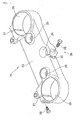
FIG. 2 is a perspective view of a top bridge. -
FIG. 3 is an exploded cross-sectional view of the steering apparatus for vehicles according to the present invention. -
FIG. 4 is a fragmentary cross-sectional view of the steering apparatus for vehicles according to the present invention. -
FIG. 5 is a view of a modification of the steering apparatus shown inFIG. 4 . - An embodiment of the present invention will be described below with reference to the accompanying drawings.
- The embodiment of the present invention will be described with reference to the drawings.
- As shown in
FIG. 1 , asteering apparatus 10 for vehicles includes astem pipe 14 angularly movably mounted in ahead pipe 11 by upper andlower bearings top bridge 15 and abottom bridge 16 mounted respectively on upper and lower ends of thestem pipe 14,front fork members 17 mounted on thetop bridge 15 and thebottom bridge 16, and asteering handle 19 mounted on thetop bridge 15 byhandle holders 18. Each of thehandle holders 18 is separable into upper and lower parts which are integrally coupled to each other by abolt 21. - As shown in
FIG. 2 , thetop bridge 15 includes a plate-like bridge body 23 having apipe insertion hole 24 defined centrally therein, bolt insertion holes 25 (holes in which the bolts on the handle holder are inserted) defined in left and right portions of the plate-like bridge body 23, and fork insertion holes 26 defined in the plate-like bridge body 23 outwardly of the bolt insertion holes 25 on their left and right sides. - The fork insertion holes 26 have a circular shape partly interrupted by
slots 27, and can be reduced in diameter byslot tightening bolts 28 threaded across theslots 27. When the fork insertion holes 26 are reduced in diameter, thefront fork members 17 are fastened to thebridge body 23. In other words, each of the fork insertion holes 26 has a slot tightening mechanism (fork slot tightening mechanism) including theslot 27 and theslot tightening bolt 28. - The central
pipe insertion hole 24 also has aslot 31, and can be reduced in diameter by aslot tightening bolt 32 threaded across theslot 31. In other words, a slot tightening mechanism (stem pipe slot tightening mechanism) 30 for reducing the diameter of thepipe insertion hole 24 including theslot 31 and theslot tightening bolt 32. - The
bottom bridge 16 shown inFIG. 1 is identical in structure to thetop bridge 15. Thus, thebottom bridge 16 has theslot tightening mechanism 30 and the slot tightening mechanism (stem pipe slot tightening mechanism) including theslot 27. - The structures of other components will be described below with reference to an exploded view of
FIG. 3 . The components will be described successively upwardly inFIG. 3 . - As shown in
FIG. 3 , thestem pipe 14 has an internally threadedsurface 34 extending axially in an upper portion thereof. Thestem pipe 14 has an outside diameter Dp and the internally threadedsurface 34 has a length Ls. - An
upper bearing 12 is mounted in an upper portion of thehead pipe 11. Thebearing 12 includes aninner race 35,steel balls 36 as rolling elements, and anouter race 37. Thebearing 12 may include an angular ball bearing as shown, or a conical roller bearing, or the like. Thebearing 12 may be of any type insofar as it can bear a radial load and a thrust road and can be preloaded. - A
seal member 38 is interposed between theupper bearing 12 and thetop bridge 15. Theseal member 38 includes aplate 39 held in contact with theinner race 35 of thebearing 12, and aresilient member 41 fitted over an outer circumferential edge of theplate 39. Theresilient member 41 includesintegral lips - The
pipe insertion hole 24 defined in thetop bridge 15 has theslot 31 and is associated with theslot tightening bolt 32. Theslot tightening bolt 32 is positioned substantially at the center of thepipe insertion hole 24 in a vertical direction or slightly above the center of thepipe insertion hole 24 for reasons described later. Thetop bridge 15 has on its lower surface a downwardly raisedbearing presser 44 for pressing theinner race 35 of theupper bearing 12. - A
fastening bolt 45, which is referred to as a top bolt, includes ahead 46 that is sufficiently larger in diameter than thepipe insertion hole 24, astep 47 extending from thehead 46 and having a diameter Db that is slightly smaller than the outside diameter Dp of thestem pipe 14, and ashank 48 extending from thestep 47 and smaller in diameter than thestep 47. Theshank 48 has an externally threadedsurface 49. Atool insertion hole 51 such as a hexagonal hole is defined centrally in thehead 46 and thestep 47. A blank hole 52 (greater in diameter than the tool insertion hole 51) is defined centrally in theshank 48. A breather tube of a fuel tank or the like can be inserted through thetool insertion hole 51 and theblank hole 52 into thestem pipe 14. - The above components are shown in an assembled state in
FIG. 4 . - As shown in
FIG. 4 , thefastening bolt 45 has thestep 47 fitted in thepipe insertion hole 24 between thehead 46 and the externally threadedsurface 49. Thestem pipe 14 is inserted in thehead pipe 11 with theupper bearing 12 and theseal member 38 interposed therebetween. The upper end of thestem pipe 14 is inserted in thetop bridge 15, and thefastening bolt 45 is threaded into the internally threadedsurface 34, preloading thebearing 12. Specifically, theinner race 35 is depressed into theouter race 37 which remains still to preload thebearing 12. - The
stem pipe 14 is firmly tightened and supported by the slot tightening mechanism 30 (FIG. 2 ). Thestep 47 is tightened when thestem pipe 14 is reduced in diameter under compressive forces. Only a tightening force required to keep thefastening bolt 45 from loosening is applied to thefastening bolt 45. In other words, since thefastening bolt 45 firmly supports thestem pipe 14 which requires a greater tightening force and thefastening bolt 45 is tightened by only a tightening force required to keep thefastening bolt 45 from loosening, thestep 47 of thefastening bolt 45 does not need to be more rigid than necessary. - It is desirable for the upper portion of the
stem pipe 14 to have aslot 55 defined therein which is longer than the internally threadedsurface 34. Thestem pipe 14 with theslot 55 can be reduced in diameter more easily when thestem pipe 14 is tightened than if theslot 55 were not defined in thestem pipe 14. - Heretofore, a double nut structure has been employed to a bolt from loosening. According to the present invention, since no double nut structure is required, the number of parts used is reduced. In addition, as the outer circumferential surface of the
stem pipe 14 does not need to be externally threaded, the cost of the threading process is lowered. - Inasmuch as the conventional double nut structure is not required, the top bridge can be positioned closely to the upper bearing, and the distance by which the stem pipe projects from the upper bearing can be reduced. Since the bending moment applied to the stem pipe is reduced and the required rigidity of the stem pipe is also reduced, the wall thickness of the stem pipe can be reduced.
- As shown in
FIG. 4 , when thesteering apparatus 10 is assembled, the internally threadedsurface 34 is spaced upwardly from the lower end of thepipe insertion hole 24 by a distance δ. Though stresses tend to concentrate on the distal end (starting thread 53) of the internally threadedsurface 34, since the distal end of the internally threadedsurface 34 is spaced upwardly from the lower end of thepipe insertion hole 24 by the distance δ, such a stress concentration can be avoided. - A line passing through the center in axial directions of the externally threaded
surface 49 of thefastening bolt 45 is defined as acentral line 54. The slot tightening bolt 32 (FIG. 3 ) is positioned on thecentral line 54 or in the neighborhood of thecentral line 54. When theslot tightening bolt 32 is tightened, thepipe insertion hole 24 is reduced in diameter, causing thestem pipe 14 to be reduced in diameter. When thestem pipe 14 is reduced in diameter, the internally threadedsurface 34 is strongly fitted over thefastening bolt 45. Therefore, thefastening bolt 45 is firmly held in place against loosening. - A plurality of slot tightening bolts may be used to adjust the torque to finer degrees at vertically spaced positions.
- The
top bridge 15 has the raisedbearing presser 44 for pressing theinner race 35 of theupper bearing 12. When the bearingpresser 44 presses theinner race 35 of theupper bearing 12, thebearing 12 is easily preloaded. Similarly, as shown inFIG. 1 , thebottom bridge 16 has a raisedbearing presser 62 for pressing the inner race of thelower bearing 13. When the raisedbearing presser 62 presses the inner race of thelower bearing 13, thebearing 13 is easily preloaded. - The
fastening bolt 45 may be replaced with a fastening nut. Such a modification will be described below with reference toFIG. 5 . Those parts shown inFIG. 5 which are identical to those shown inFIG. 4 are denoted by identical reference characters, and will not be described in detail. - As shown in
FIG. 5 , a threadedshank 57 is attached to the upper portion of thestem pipe 14. The threadedshank 57 has an externally threadedsurface 58. Afastening nut 59 is threaded over the externally threadedsurface 58. Thefastening nut 59 has astep 61 integral therewith which is inserted in thepipe insertion hole 24. - When the
pipe insertion hole 24 is reduced in diameter by the slot tightening mechanism, compressive forces are applied simultaneously to the upper portion of thestem pipe 14 and thestep 61. Since thetop bridge 15 is fixed to thestem pipe 14 and holds thestep 61 in position under frictional forces generated by the applied compressive forces, thefastening nut 59 will not tend to loosen. - In claims 2, 3, the stem pipe has a "threaded surface" which may be either the internally threaded
surface 34 or the externally threadedsurface 58. The "threaded surface" tightens a fastening member which may include a member of any kind having an externally threaded surface or an internally threaded surface which corresponds to the "threaded surface," e.g., a bolt or a nut, or any of various other equivalent members. - A slot tightening mechanism called for in
claim 1 refers to a stem pipe slot tightening mechanism. Two slot tightening mechanisms called in claim 3 refer to a stem pipe slot tightening mechanism and a fork slot tightening mechanism. - The vehicle according to the present invention is preferably a two-wheeled motorcycle, but may be a three-wheeled vehicle or a four-wheeled vehicle.
- The steering apparatus according to the present invention is preferably applicable to a two-wheeled motorcycle.
- The invention is directed to provide a steering apparatus for vehicles which is made up of a reduced number of parts.
- A
fastening bolt 45 has astep 47 disposed between ahead 46 and a threadedsurface 49 and fitted in apipe insertion hole 24. Astem pipe 14 is firmly tightened and supported by a slot tightening mechanism. Astep 47 is tightened when thestem pipe 14 is reduced in diameter under compressive forces. Only a tightening force required to keep thefastening bolt 45 from loosening is applied to thefastening bolt 45. In other words, since thefastening bolt 45 firmly supports thestem pipe 14 which requires a greater tightening force and thefastening bolt 45 is tightened by only a tightening force required to keep thefastening bolt 45 from loosening, thestep 47 of thefastening bolt 45 does not need to be more rigid than necessary. - Since a nut for keeping a bolt from loosening is not required, the number of parts is reduced.
Claims (7)
- A steering apparatus for vehicles (10), comprising a stem pipe (14) angularly movably mounted in a head pipe (11) by upper and lower bearings (12, 13) and having an internally threaded surface (34) axially extending on an upper portion thereof, a seal member (38) covering an upper surface of the upper bearing (12), a bottom bridge (16) mounted on a lower end of said stem pipe (14), a top bridge (15) having a pipe insertion hole (24) through which said stem pipe (14) is inserted and a slot fastening mechanism for changing the diameter of the pipe insertion hole (24), and a fastening bolt (45) threaded in said internally threaded surface (34) after the top bridge (15) is mounted on an upper portion of the head pipe (11), wherein
said fastening bolt (45) has a step (47) disposed between a head (46) and a threaded surface thereof and fitted in said pipe insertion hole (24); and
said stem pipe (14) is inserted in said head pipe (11) with the upper and lower bearings (12, 13) interposed therebetween, an upper end of the stem pipe (14) is inserted in said top bridge (15), then said tightening bolt is threaded in said internally threaded surface (34), thereby preloading the bearings, and the pipe insertion hole (24) is reduced in diameter by said slot tightening mechanism (30), thereby fixing said top bridge (15) to said stem pipe (14) and said step (47). - A steering apparatus for vehicles (10), comprising a stem pipe (14) angularly movably mounted in a head pipe (11) by upper and lower bearings (12, 13) and having a threaded surface (49) axially extending on an upper portion thereof, a bottom bridge (16) mounted on a lower end of said stem pipe (14), a top bridge (15) having a pipe insertion hole (24) through which said stem pipe (14) is inserted and a slot fastening mechanism for changing the diameter of the pipe insertion hole (24), and a fastening member threaded in said threaded surface (49) after the top bridge (15) is mounted on an upper portion of the head pipe (11), wherein
said bottom bridge (16) has a bearing presser (44, 62) for pressing an inner race (35) of the lower bearing (13);
said top bridge (15) has a bearing presser (44, 62) for pressing an inner race (35) of the upper bearing (12); and
said stem pipe (14) is inserted in said head pipe (11) with the upper and lower bearings (12, 13) interposed therebetween, an upper end of the stem pipe (14) is inserted in said top bridge (15), then said fastening member is threaded in said threaded surface (49), thereby preloading the bearings, and the pipe insertion hole (24) is reduced in diameter by said slot tightening mechanism (30), thereby fixing said top bridge (15) to said stem pipe (14). - A steering apparatus for vehicles (10), comprising a stem pipe (14) angularly movably mounted in a head pipe (11) by upper and lower bearings (12, 13) and having a threaded surface (49) axially extending on an upper portion thereof, a bottom bridge (16) mounted on a lower end of said stem pipe (14), a top bridge (15) having a pipe insertion hole (24) through which said stem pipe (14) is inserted and a slot fastening mechanism for changing the diameter of the pipe insertion hole (24), a fastening member threaded in said threaded surface (49) after the top bridge (15) is mounted on an upper portion of the head pipe (11), said bottom bridge (16) having fork insertion holes defined in outer left and right sides thereof and slot tightening mechanisms (30) for changing the diameters of the fork insertion holes, said top bridge (15) having fork insertion holes defined in outer left and right sides thereof and slot tightening mechanisms (30) for changing the diameters of the fork insertion holes, and a pair of left and right front fork members (17) fixedly inserted in the fork insertion holes of said bottom bridge (16) and the fork insertion holes of said top bridge (15), wherein
said bottom bridge (16) has a bearing presser (44, 62) for pressing an inner race (35) of the lower bearing (13);
said top bridge (16) has a bearing presser (44, 62) for pressing an inner race (35) of the upper bearing (12); and
said stem pipe (14) is inserted in said head pipe (11) with the upper and lower bearings (12, 13) interposed therebetween, an upper end of the stem pipe (14) is inserted in said top bridge (15), then said fastening member is threaded in said threaded surface (49), thereby preloading the bearings, and the pipe insertion hole (24) is reduced in diameter by said slot tightening mechanism (30), thereby fixing said top bridge (15) to said stem pipe (14). - The steering apparatus for vehicles (10) according to claim 1, 2, or 3, wherein said step (47) has a diameter smaller than the outside diameter of said stem pipe (14) in order to conform with the outside diameter of said stem pipe (14) when the outside diameter of said stem pipe (14) is reduced under compressive forces applied to the stem pipe (14) upon being tightened by said slot tightening mechanism (30).
- The steering apparatus for vehicles (10) according to any of claims 1 through 4, wherein said internally threaded surface (34) is spaced upwardly from the lower end of the pipe insertion hole (24) when the steering apparatus (10) is assembled.
- The steering apparatus for vehicles (10) according to any of claims 1 through 5, wherein said slot tightening mechanism (30) for reducing the diameter of said pipe insertion hole (24) is positioned in the vicinity of the center in axial directions of the threaded surface (49) of said fastening bolt (45) when the steering apparatus (10) is assembled.
- The steering apparatus for vehicles (10) according to any of claims 1 through 6, wherein said top bridge (15) has a downwardly raised bearing presser (44, 62) for pressing an inner race of the upper bearing (12).
Applications Claiming Priority (1)
| Application Number | Priority Date | Filing Date | Title |
|---|---|---|---|
| JP2009124178A JP5320162B2 (en) | 2009-05-22 | 2009-05-22 | Vehicle steering device |
Publications (2)
| Publication Number | Publication Date |
|---|---|
| EP2256021A1 true EP2256021A1 (en) | 2010-12-01 |
| EP2256021B1 EP2256021B1 (en) | 2012-06-20 |
Family
ID=42341404
Family Applications (1)
| Application Number | Title | Priority Date | Filing Date |
|---|---|---|---|
| EP10161760A Not-in-force EP2256021B1 (en) | 2009-05-22 | 2010-05-03 | Steering apparatus for vehicles |
Country Status (4)
| Country | Link |
|---|---|
| US (1) | US8528927B2 (en) |
| EP (1) | EP2256021B1 (en) |
| JP (1) | JP5320162B2 (en) |
| CN (1) | CN101890993B (en) |
Families Citing this family (5)
| Publication number | Priority date | Publication date | Assignee | Title |
|---|---|---|---|---|
| JP5863540B2 (en) * | 2012-04-02 | 2016-02-16 | 本田技研工業株式会社 | Motorcycle and front fork |
| JP5973271B2 (en) * | 2012-07-17 | 2016-08-23 | 川崎重工業株式会社 | Saddle riding vehicle |
| JP2016033002A (en) * | 2014-07-31 | 2016-03-10 | 本田技研工業株式会社 | Handle fixing structure |
| US10316950B2 (en) * | 2017-03-10 | 2019-06-11 | Arvinmeritor Technology, Llc | Axle assembly having a drive pinion and a bearing preload element |
| JP6625686B2 (en) * | 2018-03-29 | 2019-12-25 | 本田技研工業株式会社 | Saddle type vehicle |
Citations (8)
| Publication number | Priority date | Publication date | Assignee | Title |
|---|---|---|---|---|
| JPS58164882U (en) * | 1982-04-30 | 1983-11-02 | スズキ株式会社 | Motorcycle front hookup bracket |
| JPS59195480A (en) * | 1983-04-22 | 1984-11-06 | ヤマハ発動機株式会社 | Connecting bracket for front fork |
| US5078417A (en) * | 1989-07-19 | 1992-01-07 | Cycle Composites, Inc. | All terrain cycle fork with fiber reinforced resin blades and crown and method of making same |
| JPH11165684A (en) | 1997-12-08 | 1999-06-22 | Kawasaki Heavy Ind Ltd | Steering device with front fork |
| US7118302B1 (en) * | 2004-04-14 | 2006-10-10 | Oberg Industries | Vehicle clamp having a vibration dampening insert |
| EP1746018A2 (en) * | 2005-07-21 | 2007-01-24 | Yamaha Hatsudoki Kabushiki Kaisha | Handlebar assembly for motorcycle |
| EP1946863A1 (en) * | 2006-12-20 | 2008-07-23 | Yamaha Hatsudoki Kabushiki Kaisha | Forged product and method of making the product |
| US20080296861A1 (en) * | 2007-05-30 | 2008-12-04 | Yamaha Hatsudoki Kabushiki Kaisha | Bracket for fixing a fork of a vehicle |
Family Cites Families (13)
| Publication number | Priority date | Publication date | Assignee | Title |
|---|---|---|---|---|
| JPS53841Y2 (en) * | 1973-08-22 | 1978-01-12 | ||
| JPS5417242Y2 (en) * | 1974-08-21 | 1979-07-04 | ||
| JPS5591476A (en) * | 1978-12-29 | 1980-07-11 | Yamaha Motor Co Ltd | Steering gear |
| US4573698A (en) * | 1982-10-14 | 1986-03-04 | Honda Giken Kogyo Kabushiki Kaisha | Motorcycle steering mechanism |
| US5319993A (en) * | 1993-09-02 | 1994-06-14 | Tien Hsin Industries Co., Ltd. | Steering bearing assembly for a bicycle |
| US5385360A (en) * | 1993-09-17 | 1995-01-31 | Thurston, Inc. | Headset locking mechanism |
| US5540457A (en) * | 1994-08-31 | 1996-07-30 | Rocky Mountain Bicycle Company Ltd. | Steering assembly with external bearing pre-load adjustment |
| JPH08290793A (en) * | 1995-02-21 | 1996-11-05 | Marui:Kk | Ball bearing for bicycle head set and structure of its attaching part |
| JP4232997B2 (en) * | 1999-03-31 | 2009-03-04 | 本田技研工業株式会社 | Motorcycle steering device |
| US7207585B2 (en) * | 2003-07-31 | 2007-04-24 | Motoczysz Llc | Front suspension for motorcycle |
| US7571920B2 (en) * | 2006-09-21 | 2009-08-11 | Felt Racing, Llc | Bicycle front fork assembly |
| JP2008285050A (en) * | 2007-05-18 | 2008-11-27 | Yamaha Motor Co Ltd | Motorcycle front wheel support device |
| JP5226380B2 (en) * | 2007-05-30 | 2013-07-03 | ヤマハ発動機株式会社 | vehicle |
-
2009
- 2009-05-22 JP JP2009124178A patent/JP5320162B2/en not_active Expired - Fee Related
-
2010
- 2010-04-28 US US12/769,209 patent/US8528927B2/en not_active Expired - Fee Related
- 2010-05-03 EP EP10161760A patent/EP2256021B1/en not_active Not-in-force
- 2010-05-21 CN CN201010182854.8A patent/CN101890993B/en not_active Expired - Fee Related
Patent Citations (8)
| Publication number | Priority date | Publication date | Assignee | Title |
|---|---|---|---|---|
| JPS58164882U (en) * | 1982-04-30 | 1983-11-02 | スズキ株式会社 | Motorcycle front hookup bracket |
| JPS59195480A (en) * | 1983-04-22 | 1984-11-06 | ヤマハ発動機株式会社 | Connecting bracket for front fork |
| US5078417A (en) * | 1989-07-19 | 1992-01-07 | Cycle Composites, Inc. | All terrain cycle fork with fiber reinforced resin blades and crown and method of making same |
| JPH11165684A (en) | 1997-12-08 | 1999-06-22 | Kawasaki Heavy Ind Ltd | Steering device with front fork |
| US7118302B1 (en) * | 2004-04-14 | 2006-10-10 | Oberg Industries | Vehicle clamp having a vibration dampening insert |
| EP1746018A2 (en) * | 2005-07-21 | 2007-01-24 | Yamaha Hatsudoki Kabushiki Kaisha | Handlebar assembly for motorcycle |
| EP1946863A1 (en) * | 2006-12-20 | 2008-07-23 | Yamaha Hatsudoki Kabushiki Kaisha | Forged product and method of making the product |
| US20080296861A1 (en) * | 2007-05-30 | 2008-12-04 | Yamaha Hatsudoki Kabushiki Kaisha | Bracket for fixing a fork of a vehicle |
Non-Patent Citations (1)
| Title |
|---|
| ANONYMOUS: "BEDIENUNGSANLEITUNG 2006", 2004, pages 1 - Anhang 12, XP002593969, Retrieved from the Internet <URL:https://www.ktmdealer.net/uploads/models_tech_datasheets/6101F0_OM_DE.pdf> [retrieved on 20100727] * |
Also Published As
| Publication number | Publication date |
|---|---|
| CN101890993A (en) | 2010-11-24 |
| US20100295266A1 (en) | 2010-11-25 |
| JP2010269727A (en) | 2010-12-02 |
| US8528927B2 (en) | 2013-09-10 |
| JP5320162B2 (en) | 2013-10-23 |
| CN101890993B (en) | 2015-04-08 |
| EP2256021B1 (en) | 2012-06-20 |
Similar Documents
| Publication | Publication Date | Title |
|---|---|---|
| US7946659B2 (en) | Thru-axle system for wheel securement | |
| EP2256021B1 (en) | Steering apparatus for vehicles | |
| US6186027B1 (en) | Handlebar stem assembly for bicycle fork | |
| US7192044B2 (en) | Bicycle headset | |
| US7537291B2 (en) | Bicycle wheel securing structure | |
| US20110140391A1 (en) | Bicycle front fork assembly | |
| US7976045B2 (en) | Bicycle front fork assembly | |
| US20110097176A1 (en) | Fastening method for a fastening bolt of a sub frame to car body and a sub frame rigid collar for car used for the fastening method | |
| EP2735747B1 (en) | Nut rotation prevention structure | |
| JP5931138B2 (en) | Steering stem assembly for motorcycles | |
| EP2390111A1 (en) | Bicycle wheel spoke assembly | |
| JP5593251B2 (en) | Fastening structure for steering stem of saddle riding type vehicle | |
| JP6055079B2 (en) | Mounting structure | |
| US20060288818A1 (en) | Attachment group of a pedal crank to the central axle of a bottom bracket of a bicycle transmission | |
| JP2020040640A (en) | Structure of bicycle front fork split type headset | |
| JP2007303486A (en) | Fastening device | |
| US6474192B2 (en) | Bottom bracket bearing axle mounting arrangement | |
| JP3158339U (en) | King pin bearing pressure adjustment mechanism | |
| KR101463747B1 (en) | Tool For Insetting Bracket Bearing For Cycle | |
| JP5241676B2 (en) | Steering wheel fastening structure | |
| CN223546124U (en) | Front axle rod member structure, front axle assembly and vehicle | |
| US20160348702A1 (en) | Device configured for preloading bearing interfaces coupling concentrically arranged tubes | |
| JP2008230374A (en) | Wheel mounting structure and spacer | |
| JP2008215501A (en) | Nut with flange and bolt with flange | |
| JP3983197B2 (en) | Assembly type internal broach |
Legal Events
| Date | Code | Title | Description |
|---|---|---|---|
| PUAI | Public reference made under article 153(3) epc to a published international application that has entered the european phase |
Free format text: ORIGINAL CODE: 0009012 |
|
| 17P | Request for examination filed |
Effective date: 20100503 |
|
| AK | Designated contracting states |
Kind code of ref document: A1 Designated state(s): AL AT BE BG CH CY CZ DE DK EE ES FI FR GB GR HR HU IE IS IT LI LT LU LV MC MK MT NL NO PL PT RO SE SI SK SM TR |
|
| AX | Request for extension of the european patent |
Extension state: BA ME RS |
|
| GRAP | Despatch of communication of intention to grant a patent |
Free format text: ORIGINAL CODE: EPIDOSNIGR1 |
|
| RIC1 | Information provided on ipc code assigned before grant |
Ipc: B62K 21/06 20060101AFI20111125BHEP Ipc: B62K 21/04 20060101ALI20111125BHEP |
|
| GRAS | Grant fee paid |
Free format text: ORIGINAL CODE: EPIDOSNIGR3 |
|
| GRAA | (expected) grant |
Free format text: ORIGINAL CODE: 0009210 |
|
| AK | Designated contracting states |
Kind code of ref document: B1 Designated state(s): AL AT BE BG CH CY CZ DE DK EE ES FI FR GB GR HR HU IE IS IT LI LT LU LV MC MK MT NL NO PL PT RO SE SI SK SM TR |
|
| REG | Reference to a national code |
Ref country code: GB Ref legal event code: FG4D |
|
| REG | Reference to a national code |
Ref country code: CH Ref legal event code: EP |
|
| REG | Reference to a national code |
Ref country code: AT Ref legal event code: REF Ref document number: 562908 Country of ref document: AT Kind code of ref document: T Effective date: 20120715 |
|
| REG | Reference to a national code |
Ref country code: IE Ref legal event code: FG4D |
|
| REG | Reference to a national code |
Ref country code: DE Ref legal event code: R096 Ref document number: 602010001916 Country of ref document: DE Effective date: 20120816 |
|
| PG25 | Lapsed in a contracting state [announced via postgrant information from national office to epo] |
Ref country code: NO Free format text: LAPSE BECAUSE OF FAILURE TO SUBMIT A TRANSLATION OF THE DESCRIPTION OR TO PAY THE FEE WITHIN THE PRESCRIBED TIME-LIMIT Effective date: 20120920 Ref country code: LT Free format text: LAPSE BECAUSE OF FAILURE TO SUBMIT A TRANSLATION OF THE DESCRIPTION OR TO PAY THE FEE WITHIN THE PRESCRIBED TIME-LIMIT Effective date: 20120620 Ref country code: SE Free format text: LAPSE BECAUSE OF FAILURE TO SUBMIT A TRANSLATION OF THE DESCRIPTION OR TO PAY THE FEE WITHIN THE PRESCRIBED TIME-LIMIT Effective date: 20120620 Ref country code: FI Free format text: LAPSE BECAUSE OF FAILURE TO SUBMIT A TRANSLATION OF THE DESCRIPTION OR TO PAY THE FEE WITHIN THE PRESCRIBED TIME-LIMIT Effective date: 20120620 |
|
| REG | Reference to a national code |
Ref country code: NL Ref legal event code: VDEP Effective date: 20120620 |
|
| REG | Reference to a national code |
Ref country code: AT Ref legal event code: MK05 Ref document number: 562908 Country of ref document: AT Kind code of ref document: T Effective date: 20120620 |
|
| REG | Reference to a national code |
Ref country code: LT Ref legal event code: MG4D Effective date: 20120620 |
|
| PG25 | Lapsed in a contracting state [announced via postgrant information from national office to epo] |
Ref country code: SI Free format text: LAPSE BECAUSE OF FAILURE TO SUBMIT A TRANSLATION OF THE DESCRIPTION OR TO PAY THE FEE WITHIN THE PRESCRIBED TIME-LIMIT Effective date: 20120620 Ref country code: HR Free format text: LAPSE BECAUSE OF FAILURE TO SUBMIT A TRANSLATION OF THE DESCRIPTION OR TO PAY THE FEE WITHIN THE PRESCRIBED TIME-LIMIT Effective date: 20120620 Ref country code: GR Free format text: LAPSE BECAUSE OF FAILURE TO SUBMIT A TRANSLATION OF THE DESCRIPTION OR TO PAY THE FEE WITHIN THE PRESCRIBED TIME-LIMIT Effective date: 20120921 Ref country code: LV Free format text: LAPSE BECAUSE OF FAILURE TO SUBMIT A TRANSLATION OF THE DESCRIPTION OR TO PAY THE FEE WITHIN THE PRESCRIBED TIME-LIMIT Effective date: 20120620 |
|
| PG25 | Lapsed in a contracting state [announced via postgrant information from national office to epo] |
Ref country code: IS Free format text: LAPSE BECAUSE OF FAILURE TO SUBMIT A TRANSLATION OF THE DESCRIPTION OR TO PAY THE FEE WITHIN THE PRESCRIBED TIME-LIMIT Effective date: 20121020 Ref country code: CZ Free format text: LAPSE BECAUSE OF FAILURE TO SUBMIT A TRANSLATION OF THE DESCRIPTION OR TO PAY THE FEE WITHIN THE PRESCRIBED TIME-LIMIT Effective date: 20120620 Ref country code: CY Free format text: LAPSE BECAUSE OF FAILURE TO SUBMIT A TRANSLATION OF THE DESCRIPTION OR TO PAY THE FEE WITHIN THE PRESCRIBED TIME-LIMIT Effective date: 20120620 Ref country code: RO Free format text: LAPSE BECAUSE OF FAILURE TO SUBMIT A TRANSLATION OF THE DESCRIPTION OR TO PAY THE FEE WITHIN THE PRESCRIBED TIME-LIMIT Effective date: 20120620 Ref country code: AT Free format text: LAPSE BECAUSE OF FAILURE TO SUBMIT A TRANSLATION OF THE DESCRIPTION OR TO PAY THE FEE WITHIN THE PRESCRIBED TIME-LIMIT Effective date: 20120620 Ref country code: BE Free format text: LAPSE BECAUSE OF FAILURE TO SUBMIT A TRANSLATION OF THE DESCRIPTION OR TO PAY THE FEE WITHIN THE PRESCRIBED TIME-LIMIT Effective date: 20120620 Ref country code: SK Free format text: LAPSE BECAUSE OF FAILURE TO SUBMIT A TRANSLATION OF THE DESCRIPTION OR TO PAY THE FEE WITHIN THE PRESCRIBED TIME-LIMIT Effective date: 20120620 Ref country code: EE Free format text: LAPSE BECAUSE OF FAILURE TO SUBMIT A TRANSLATION OF THE DESCRIPTION OR TO PAY THE FEE WITHIN THE PRESCRIBED TIME-LIMIT Effective date: 20120620 |
|
| PG25 | Lapsed in a contracting state [announced via postgrant information from national office to epo] |
Ref country code: PL Free format text: LAPSE BECAUSE OF FAILURE TO SUBMIT A TRANSLATION OF THE DESCRIPTION OR TO PAY THE FEE WITHIN THE PRESCRIBED TIME-LIMIT Effective date: 20120620 Ref country code: PT Free format text: LAPSE BECAUSE OF FAILURE TO SUBMIT A TRANSLATION OF THE DESCRIPTION OR TO PAY THE FEE WITHIN THE PRESCRIBED TIME-LIMIT Effective date: 20121022 |
|
| PG25 | Lapsed in a contracting state [announced via postgrant information from national office to epo] |
Ref country code: NL Free format text: LAPSE BECAUSE OF FAILURE TO SUBMIT A TRANSLATION OF THE DESCRIPTION OR TO PAY THE FEE WITHIN THE PRESCRIBED TIME-LIMIT Effective date: 20120620 |
|
| PLBE | No opposition filed within time limit |
Free format text: ORIGINAL CODE: 0009261 |
|
| STAA | Information on the status of an ep patent application or granted ep patent |
Free format text: STATUS: NO OPPOSITION FILED WITHIN TIME LIMIT |
|
| PG25 | Lapsed in a contracting state [announced via postgrant information from national office to epo] |
Ref country code: ES Free format text: LAPSE BECAUSE OF FAILURE TO SUBMIT A TRANSLATION OF THE DESCRIPTION OR TO PAY THE FEE WITHIN THE PRESCRIBED TIME-LIMIT Effective date: 20121001 Ref country code: DK Free format text: LAPSE BECAUSE OF FAILURE TO SUBMIT A TRANSLATION OF THE DESCRIPTION OR TO PAY THE FEE WITHIN THE PRESCRIBED TIME-LIMIT Effective date: 20120620 |
|
| 26N | No opposition filed |
Effective date: 20130321 |
|
| REG | Reference to a national code |
Ref country code: DE Ref legal event code: R097 Ref document number: 602010001916 Country of ref document: DE Effective date: 20130321 |
|
| PG25 | Lapsed in a contracting state [announced via postgrant information from national office to epo] |
Ref country code: BG Free format text: LAPSE BECAUSE OF FAILURE TO SUBMIT A TRANSLATION OF THE DESCRIPTION OR TO PAY THE FEE WITHIN THE PRESCRIBED TIME-LIMIT Effective date: 20120920 |
|
| PG25 | Lapsed in a contracting state [announced via postgrant information from national office to epo] |
Ref country code: MC Free format text: LAPSE BECAUSE OF FAILURE TO SUBMIT A TRANSLATION OF THE DESCRIPTION OR TO PAY THE FEE WITHIN THE PRESCRIBED TIME-LIMIT Effective date: 20120620 |
|
| REG | Reference to a national code |
Ref country code: IE Ref legal event code: MM4A |
|
| PG25 | Lapsed in a contracting state [announced via postgrant information from national office to epo] |
Ref country code: IE Free format text: LAPSE BECAUSE OF NON-PAYMENT OF DUE FEES Effective date: 20130503 |
|
| REG | Reference to a national code |
Ref country code: CH Ref legal event code: PL |
|
| GBPC | Gb: european patent ceased through non-payment of renewal fee |
Effective date: 20140503 |
|
| PG25 | Lapsed in a contracting state [announced via postgrant information from national office to epo] |
Ref country code: LI Free format text: LAPSE BECAUSE OF NON-PAYMENT OF DUE FEES Effective date: 20140531 Ref country code: CH Free format text: LAPSE BECAUSE OF NON-PAYMENT OF DUE FEES Effective date: 20140531 |
|
| PG25 | Lapsed in a contracting state [announced via postgrant information from national office to epo] |
Ref country code: MT Free format text: LAPSE BECAUSE OF FAILURE TO SUBMIT A TRANSLATION OF THE DESCRIPTION OR TO PAY THE FEE WITHIN THE PRESCRIBED TIME-LIMIT Effective date: 20120620 |
|
| PG25 | Lapsed in a contracting state [announced via postgrant information from national office to epo] |
Ref country code: GB Free format text: LAPSE BECAUSE OF NON-PAYMENT OF DUE FEES Effective date: 20140503 Ref country code: SM Free format text: LAPSE BECAUSE OF FAILURE TO SUBMIT A TRANSLATION OF THE DESCRIPTION OR TO PAY THE FEE WITHIN THE PRESCRIBED TIME-LIMIT Effective date: 20120620 |
|
| PG25 | Lapsed in a contracting state [announced via postgrant information from national office to epo] |
Ref country code: TR Free format text: LAPSE BECAUSE OF FAILURE TO SUBMIT A TRANSLATION OF THE DESCRIPTION OR TO PAY THE FEE WITHIN THE PRESCRIBED TIME-LIMIT Effective date: 20120620 |
|
| PG25 | Lapsed in a contracting state [announced via postgrant information from national office to epo] |
Ref country code: MK Free format text: LAPSE BECAUSE OF FAILURE TO SUBMIT A TRANSLATION OF THE DESCRIPTION OR TO PAY THE FEE WITHIN THE PRESCRIBED TIME-LIMIT Effective date: 20120620 Ref country code: HU Free format text: LAPSE BECAUSE OF FAILURE TO SUBMIT A TRANSLATION OF THE DESCRIPTION OR TO PAY THE FEE WITHIN THE PRESCRIBED TIME-LIMIT; INVALID AB INITIO Effective date: 20100503 Ref country code: LU Free format text: LAPSE BECAUSE OF NON-PAYMENT OF DUE FEES Effective date: 20130503 |
|
| REG | Reference to a national code |
Ref country code: FR Ref legal event code: PLFP Year of fee payment: 7 |
|
| REG | Reference to a national code |
Ref country code: FR Ref legal event code: PLFP Year of fee payment: 8 |
|
| PGFP | Annual fee paid to national office [announced via postgrant information from national office to epo] |
Ref country code: FR Payment date: 20170413 Year of fee payment: 8 |
|
| PGFP | Annual fee paid to national office [announced via postgrant information from national office to epo] |
Ref country code: IT Payment date: 20180522 Year of fee payment: 9 |
|
| PG25 | Lapsed in a contracting state [announced via postgrant information from national office to epo] |
Ref country code: AL Free format text: LAPSE BECAUSE OF FAILURE TO SUBMIT A TRANSLATION OF THE DESCRIPTION OR TO PAY THE FEE WITHIN THE PRESCRIBED TIME-LIMIT Effective date: 20120620 |
|
| PG25 | Lapsed in a contracting state [announced via postgrant information from national office to epo] |
Ref country code: FR Free format text: LAPSE BECAUSE OF NON-PAYMENT OF DUE FEES Effective date: 20180531 |
|
| PGFP | Annual fee paid to national office [announced via postgrant information from national office to epo] |
Ref country code: DE Payment date: 20190423 Year of fee payment: 10 |
|
| REG | Reference to a national code |
Ref country code: DE Ref legal event code: R084 Ref document number: 602010001916 Country of ref document: DE |
|
| PG25 | Lapsed in a contracting state [announced via postgrant information from national office to epo] |
Ref country code: IT Free format text: LAPSE BECAUSE OF NON-PAYMENT OF DUE FEES Effective date: 20190503 |
|
| REG | Reference to a national code |
Ref country code: DE Ref legal event code: R119 Ref document number: 602010001916 Country of ref document: DE |
|
| PG25 | Lapsed in a contracting state [announced via postgrant information from national office to epo] |
Ref country code: DE Free format text: LAPSE BECAUSE OF NON-PAYMENT OF DUE FEES Effective date: 20201201 |