EP2255872A2 - Catalytic combustor and fuel reformer having the same - Google Patents
Catalytic combustor and fuel reformer having the same Download PDFInfo
- Publication number
- EP2255872A2 EP2255872A2 EP10250127A EP10250127A EP2255872A2 EP 2255872 A2 EP2255872 A2 EP 2255872A2 EP 10250127 A EP10250127 A EP 10250127A EP 10250127 A EP10250127 A EP 10250127A EP 2255872 A2 EP2255872 A2 EP 2255872A2
- Authority
- EP
- European Patent Office
- Prior art keywords
- fuel
- catalytic combustor
- reaction
- catalyst layer
- reaction portion
- Prior art date
- Legal status (The legal status is an assumption and is not a legal conclusion. Google has not performed a legal analysis and makes no representation as to the accuracy of the status listed.)
- Withdrawn
Links
Images


Classifications
-
- B—PERFORMING OPERATIONS; TRANSPORTING
- B01—PHYSICAL OR CHEMICAL PROCESSES OR APPARATUS IN GENERAL
- B01J—CHEMICAL OR PHYSICAL PROCESSES, e.g. CATALYSIS OR COLLOID CHEMISTRY; THEIR RELEVANT APPARATUS
- B01J19/00—Chemical, physical or physico-chemical processes in general; Their relevant apparatus
- B01J19/24—Stationary reactors without moving elements inside
- B01J19/248—Reactors comprising multiple separated flow channels
- B01J19/2485—Monolithic reactors
-
- F—MECHANICAL ENGINEERING; LIGHTING; HEATING; WEAPONS; BLASTING
- F23—COMBUSTION APPARATUS; COMBUSTION PROCESSES
- F23C—METHODS OR APPARATUS FOR COMBUSTION USING FLUID FUEL OR SOLID FUEL SUSPENDED IN A CARRIER GAS OR AIR
- F23C13/00—Apparatus in which combustion takes place in the presence of catalytic material
- F23C13/04—Apparatus in which combustion takes place in the presence of catalytic material characterised by arrangements of two or more catalytic elements in series connection
-
- B—PERFORMING OPERATIONS; TRANSPORTING
- B01—PHYSICAL OR CHEMICAL PROCESSES OR APPARATUS IN GENERAL
- B01J—CHEMICAL OR PHYSICAL PROCESSES, e.g. CATALYSIS OR COLLOID CHEMISTRY; THEIR RELEVANT APPARATUS
- B01J19/00—Chemical, physical or physico-chemical processes in general; Their relevant apparatus
- B01J19/24—Stationary reactors without moving elements inside
- B01J19/248—Reactors comprising multiple separated flow channels
- B01J19/2495—Net-type reactors
-
- C—CHEMISTRY; METALLURGY
- C01—INORGANIC CHEMISTRY
- C01B—NON-METALLIC ELEMENTS; COMPOUNDS THEREOF; METALLOIDS OR COMPOUNDS THEREOF NOT COVERED BY SUBCLASS C01C
- C01B3/00—Hydrogen; Gaseous mixtures containing hydrogen; Separation of hydrogen from mixtures containing it; Purification of hydrogen; Reversible storage of hydrogen
- C01B3/02—Production of hydrogen; Production of gaseous mixtures containing hydrogen
- C01B3/32—Production of hydrogen; Production of gaseous mixtures containing hydrogen by reaction of gaseous or liquid organic compounds with gasifying agents, e.g. water, carbon dioxide or air
- C01B3/34—Production of hydrogen; Production of gaseous mixtures containing hydrogen by reaction of gaseous or liquid organic compounds with gasifying agents, e.g. water, carbon dioxide or air by reaction of hydrocarbons with gasifying agents
-
- F—MECHANICAL ENGINEERING; LIGHTING; HEATING; WEAPONS; BLASTING
- F23—COMBUSTION APPARATUS; COMBUSTION PROCESSES
- F23C—METHODS OR APPARATUS FOR COMBUSTION USING FLUID FUEL OR SOLID FUEL SUSPENDED IN A CARRIER GAS OR AIR
- F23C6/00—Combustion apparatus characterised by the combination of two or more combustion chambers or combustion zones, e.g. for staged combustion
- F23C6/04—Combustion apparatus characterised by the combination of two or more combustion chambers or combustion zones, e.g. for staged combustion in series connection
- F23C6/045—Combustion apparatus characterised by the combination of two or more combustion chambers or combustion zones, e.g. for staged combustion in series connection with staged combustion in a single enclosure
- F23C6/047—Combustion apparatus characterised by the combination of two or more combustion chambers or combustion zones, e.g. for staged combustion in series connection with staged combustion in a single enclosure with fuel supply in stages
-
- H—ELECTRICITY
- H01—ELECTRIC ELEMENTS
- H01M—PROCESSES OR MEANS, e.g. BATTERIES, FOR THE DIRECT CONVERSION OF CHEMICAL ENERGY INTO ELECTRICAL ENERGY
- H01M8/00—Fuel cells; Manufacture thereof
- H01M8/04—Auxiliary arrangements, e.g. for control of pressure or for circulation of fluids
-
- B—PERFORMING OPERATIONS; TRANSPORTING
- B01—PHYSICAL OR CHEMICAL PROCESSES OR APPARATUS IN GENERAL
- B01J—CHEMICAL OR PHYSICAL PROCESSES, e.g. CATALYSIS OR COLLOID CHEMISTRY; THEIR RELEVANT APPARATUS
- B01J2219/00—Chemical, physical or physico-chemical processes in general; Their relevant apparatus
- B01J2219/00049—Controlling or regulating processes
- B01J2219/00051—Controlling the temperature
- B01J2219/00074—Controlling the temperature by indirect heating or cooling employing heat exchange fluids
- B01J2219/00117—Controlling the temperature by indirect heating or cooling employing heat exchange fluids with two or more reactions in heat exchange with each other, such as an endothermic reaction in heat exchange with an exothermic reaction
-
- C—CHEMISTRY; METALLURGY
- C01—INORGANIC CHEMISTRY
- C01B—NON-METALLIC ELEMENTS; COMPOUNDS THEREOF; METALLOIDS OR COMPOUNDS THEREOF NOT COVERED BY SUBCLASS C01C
- C01B2203/00—Integrated processes for the production of hydrogen or synthesis gas
- C01B2203/02—Processes for making hydrogen or synthesis gas
- C01B2203/0205—Processes for making hydrogen or synthesis gas containing a reforming step
- C01B2203/0227—Processes for making hydrogen or synthesis gas containing a reforming step containing a catalytic reforming step
- C01B2203/0233—Processes for making hydrogen or synthesis gas containing a reforming step containing a catalytic reforming step the reforming step being a steam reforming step
-
- C—CHEMISTRY; METALLURGY
- C01—INORGANIC CHEMISTRY
- C01B—NON-METALLIC ELEMENTS; COMPOUNDS THEREOF; METALLOIDS OR COMPOUNDS THEREOF NOT COVERED BY SUBCLASS C01C
- C01B2203/00—Integrated processes for the production of hydrogen or synthesis gas
- C01B2203/06—Integration with other chemical processes
- C01B2203/066—Integration with other chemical processes with fuel cells
-
- C—CHEMISTRY; METALLURGY
- C01—INORGANIC CHEMISTRY
- C01B—NON-METALLIC ELEMENTS; COMPOUNDS THEREOF; METALLOIDS OR COMPOUNDS THEREOF NOT COVERED BY SUBCLASS C01C
- C01B2203/00—Integrated processes for the production of hydrogen or synthesis gas
- C01B2203/08—Methods of heating or cooling
- C01B2203/0805—Methods of heating the process for making hydrogen or synthesis gas
- C01B2203/0811—Methods of heating the process for making hydrogen or synthesis gas by combustion of fuel
- C01B2203/0822—Methods of heating the process for making hydrogen or synthesis gas by combustion of fuel the fuel containing hydrogen
-
- C—CHEMISTRY; METALLURGY
- C01—INORGANIC CHEMISTRY
- C01B—NON-METALLIC ELEMENTS; COMPOUNDS THEREOF; METALLOIDS OR COMPOUNDS THEREOF NOT COVERED BY SUBCLASS C01C
- C01B2203/00—Integrated processes for the production of hydrogen or synthesis gas
- C01B2203/08—Methods of heating or cooling
- C01B2203/0805—Methods of heating the process for making hydrogen or synthesis gas
- C01B2203/0811—Methods of heating the process for making hydrogen or synthesis gas by combustion of fuel
- C01B2203/0827—Methods of heating the process for making hydrogen or synthesis gas by combustion of fuel at least part of the fuel being a recycle stream
-
- F—MECHANICAL ENGINEERING; LIGHTING; HEATING; WEAPONS; BLASTING
- F23—COMBUSTION APPARATUS; COMBUSTION PROCESSES
- F23C—METHODS OR APPARATUS FOR COMBUSTION USING FLUID FUEL OR SOLID FUEL SUSPENDED IN A CARRIER GAS OR AIR
- F23C2900/00—Special features of, or arrangements for combustion apparatus using fluid fuels or solid fuels suspended in air; Combustion processes therefor
- F23C2900/03002—Combustion apparatus adapted for incorporating a fuel reforming device
-
- Y—GENERAL TAGGING OF NEW TECHNOLOGICAL DEVELOPMENTS; GENERAL TAGGING OF CROSS-SECTIONAL TECHNOLOGIES SPANNING OVER SEVERAL SECTIONS OF THE IPC; TECHNICAL SUBJECTS COVERED BY FORMER USPC CROSS-REFERENCE ART COLLECTIONS [XRACs] AND DIGESTS
- Y02—TECHNOLOGIES OR APPLICATIONS FOR MITIGATION OR ADAPTATION AGAINST CLIMATE CHANGE
- Y02E—REDUCTION OF GREENHOUSE GAS [GHG] EMISSIONS, RELATED TO ENERGY GENERATION, TRANSMISSION OR DISTRIBUTION
- Y02E60/00—Enabling technologies; Technologies with a potential or indirect contribution to GHG emissions mitigation
- Y02E60/30—Hydrogen technology
- Y02E60/50—Fuel cells
-
- Y—GENERAL TAGGING OF NEW TECHNOLOGICAL DEVELOPMENTS; GENERAL TAGGING OF CROSS-SECTIONAL TECHNOLOGIES SPANNING OVER SEVERAL SECTIONS OF THE IPC; TECHNICAL SUBJECTS COVERED BY FORMER USPC CROSS-REFERENCE ART COLLECTIONS [XRACs] AND DIGESTS
- Y02—TECHNOLOGIES OR APPLICATIONS FOR MITIGATION OR ADAPTATION AGAINST CLIMATE CHANGE
- Y02P—CLIMATE CHANGE MITIGATION TECHNOLOGIES IN THE PRODUCTION OR PROCESSING OF GOODS
- Y02P20/00—Technologies relating to chemical industry
- Y02P20/10—Process efficiency
Definitions
- the following description relates to a catalytic combustor capable of inducing oxidation of a fuel and improving the thermal efficiency of a reactor, and a fuel reformer having the same.
- a combustor is a device that generates heat and high-temperature gas by oxidizing a fuel.
- the heat and high-temperature gas, generated from the combustor may be used for reforming reaction of a reformer, preheating of fuel or water, and the like.
- the combustor may be manufactured in such a manner that allows a fuel sprayed into a combustion chamber to be directly burned, that allows a fuel to be burned through an oxidation catalyst, or the like.
- the device that allows a fuel to be oxidized through an oxidation catalyst is referred to as a catalytic combustor.
- a catalytic combustor allows a fuel to be burned (or oxidized) through contact with a catalyst at a lower operating temperature than that of a direct burning type combustor such as a burner. Therefore, in order to improve efficiency, the catalytic combustor is typically manufactured to have a faster space velocity than that in the direct combustor. In addition, the catalytic combustor is less expensive to operate and generates less nitrogen oxide than the direct burning type combustor.
- the catalytic combustor allows a fuel to be burned at a relatively low temperature.
- An aspect of the present invention is directed toward a catalytic combustor capable of inducing the complete oxidation of a fuel and improving the thermal efficiency of a reactor by utilizing a dual oxidation structure.
- Another aspect of the present invention is directed toward a catalytic combustor capable of inducing the complete oxidation of a fuel and improving the thermal efficiency of a reactor by utilizing a dual oxidation structure and a dual fuel structure.
- Another aspect of the present invention is directed toward a fuel reformer having the aforementioned catalytic combustor.
- a catalytic combustor includes a housing having a cylindrical first reaction portion and a second reaction portion surrounding the first reaction portion in a double tube shape, the housing having a first opening for supplying a first fuel and an oxidant to the first reaction portion and a second opening through which an exhaust in the second reaction portion is discharged, the first and second openings being respectively disposed at first sides of the first and second reaction portions, and the first and second reaction portions being connected with each other at second sides of the first and second reaction portions so that the flow of a fluid in the first and second reaction portions forms a counter flow; a catalyst layer disposed in the first reaction portion; and a mesh layer inserted into the second reaction portion.
- the catalyst layer is disposed at a rear-end portion of the first reaction portion and the mesh layer is disposed to be adjacent to the catalyst layer so that the mesh layer is accordingly heated by a heat energy from the first reaction portion.
- a catalytic combustor which includes a housing having a cylindrical first reaction portion and a second reaction portion surrounding the first reaction portion in a double tube shape, the housing having a first opening for supplying a first fuel and an oxidant to the first reaction portion and a second opening through which an exhaust in the second reaction portion is discharged, the first and second openings being respectively disposed at first sides of the first and second reaction portions, and the first and second reaction portions being connected with each other at second sides of the first and second reaction portions so that the flow of a fluid in the first and second reaction portions forms a counter flow; a first catalyst layer disposed in the first reaction portion; and a second catalyst layer disposed in the second reaction portion.
- the catalyst layer is disposed at a rear-end portion of the first reaction portion.
- the second catalyst layer may include a mesh layer and an active material coupled with the mesh layer. Further, the active material amount of the active material used in the second catalyst layer is less than that in the first catalyst layer. In one embodiment, the active material may be coated at a density between about 0.01 and 0.4g per 1cc of the mesh layer.
- a catalytic combustor which includes a housing having a cylindrical first reaction portion and a second reaction portion surrounding the first reaction portion in a double tube shape, the housing having a first opening for supplying a first fuel and an oxidant to the first reaction portion and a second opening through which an exhaust in the second reaction portion is discharged, the first and second openings being respectively disposed at first sides of the first and second reaction portions, and the first and second reaction portions being connected with each other at second sides of the first and second reaction portions so that the flow of a fluid in the first and second reaction portions forms a counter flow; a first catalyst layer disposed in the first reaction portion; a mesh layer disposed into the second reaction portion; and a fuel supply path for supplying a second fuel between the first and second reaction portions.
- the catalyst layer is disposed at a rear-end portion of the first reaction portion and the mesh layer is disposed adjacent to the catalyst layer.
- the fuel supply path is configured to supply the second fuel in an amount between about 1 and 15% of the supply amount of the first fuel.
- the second fuel may include an off gas containing hydrogen, exhausted from an anode of a fuel cell.
- a catalytic combustor which includes a housing having a cylindrical first reaction portion and a second reaction portion surrounding the first reaction portion in a double tube shape, the housing having a first opening for supplying a first fuel and an oxidant to the first reaction portion and a second opening through which an exhaust in the second reaction portion is discharged, the first and second openings being respectively disposed at first sides of the first and second reaction portions, and the first and second reaction portions being connected with each other at second sides of the first and second reaction portions so that the flow of a fluid in the first and second reaction portions forms a counter flow; a first catalyst layer disposed in the first reaction portion; a second catalyst layer disposed in the second reaction portion; and a fuel supply path for supplying a second fuel between the first and second reaction portions.
- the first catalyst layer is disposed at a rear-end portion of the first reaction portion.
- the second catalyst layer may include a mesh layer and an active material coated on the mesh layer. Further, in one embodiment, the active material amount used in the second catalyst layer is less than that in the first catalyst layer. In one embodiment, the active material may be coated at a density between about 0.01 and 0.4g per 1cc of the mesh layer.
- the fuel supply path is configured to supply the second fuel in an amount between about 1 and 15% of the supply amount of the first fuel.
- the second fuel may include an off gas containing hydrogen, exhausted from an anode of a fuel cell.
- the first catalyst may include a metallic honeycomb support having durability at a high temperature and an active material coupled with the support.
- the cell density of the honeycomb support in the first catalyst layer may be between about 400 and about 600 cells per square inch.
- the catalytic combustor may further include a distributing portion disposed at an upstream side of the first catalyst layer based on the flow of the fuel.
- the distributing portion may be formed of a metallic honeycomb monolith having durability at a high temperature.
- the space velocity of a fluid in the distributing portion may be faster than that of a fluid in the first catalyst layer.
- the space velocity of the fluid in the first catalyst layer may be between about 1000 and about 50,000/hr.
- the cell density of the honeycomb monolith in the distributing portion is less than that of the honeycomb support in the first catalyst layer.
- the cell density of the honeycomb monolith in the distributing portion may be between about 100 and about 200 cells per square inch.
- the catalytic combustor may further include a flashback arresting portion disposed at an upstream side of the distributing portion based on the flow of the fluid.
- the flashback arresting portion may be formed of a metallic honeycomb monolith having durability at a high temperature.
- the cell density of the honeycomb monolith in the flashback arresting portion may be the same as that of the honeycomb monolith in the distributing portion.
- the first catalyst layer and/or second catalyst layer may include palladium(Pd), platinum(Pt), Co 3 O 4 , PdO, Cr 2 O 3 , Mn 2 O 3 , CuO, Fe 2 O 3 , V 2 O 3 , NiO, MoO 3 , and/or TiO 2 .
- the mesh layer may be formed of a metallic honeycomb monolith having durability at a high temperature.
- the mesh layer may be formed into a two-stage structure.
- the cell density of the honeycomb monolith in the mesh layer may be between about 50 and about 1000 cells per square inch.
- a fuel reformer which includes any one of the catalytic combustors according to the embodiments of the present invention; and a reforming reaction portion for generating a reformate by receiving heat energy generated from the catalytic combustor and for reforming a fuel.
- a fuel is more completely oxidized in a catalytic combustor.
- the catalytic combustor allows a thermal gradient to be uniform by using conduction and convection in the dual oxidation structure, so that hot spots are reduced. Accordingly, the thermal efficiency of the catalytic combustor can be considerably improved.
- an oxidation catalyst may be used only at a front end in the dual oxidation structure, i.e., a small amount of catalyst is used, the complete oxidation of a fuel can still be easily induced. Further, it is possible to improve the performance and efficiency of a fuel reformer having the catalytic combustor.
- FIG. 1 is a schematic perspective view of a catalytic combustor according to an embodiment of the present invention.
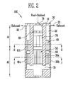
- FIG. 2 is a schematic longitudinal sectional view of the catalytic combustor of FIG. 1 .
- FIG. 3 is a schematic cross-sectional view of the catalytic combustor according to the embodiment of FIG. 1 .
- FIG. 4 is another schematic cross-sectional view of the catalytic combustor according to the embodiment of FIG. 1 .
- FIG. 5 is a schematic cross-sectional view of a catalytic combustor according to another embodiment of the present invention.
- FIG. 6 is a schematic perspective view of a catalytic combustor according to still another embodiment of the present invention.
- FIG. 7 is a schematic longitudinal sectional view of the catalytic combustor of FIG. 6 .
- FIG. 8 is a schematic block diagram of a fuel cell system for describing an application of the catalytic combustor of FIG. 6 .
- FIG. 1 is a schematic perspective view of a catalytic combustor according to an embodiment of the present invention.
- FIG. 2 is a schematic longitudinal sectional view of the catalytic combustor of FIG. 1 .
- FIG. 3 is a schematic cross-sectional view of the catalytic combustor according to the embodiment of the present invention. The cross-sectional view of FIG. 3 corresponds to a cross-sectional view taken along line I-I of FIG. 2 (or a corresponding cross-sectional view of the catalytic combustor of FIG. 1 ).
- FIG. 4 is another schematic cross-sectional view of the catalytic combustor according to the embodiment of the present invention. The cross-sectional view of FIG. 4 corresponds to a cross-sectional view taken along line II-II of FIG. 2 (or a corresponding cross-sectional view of the catalytic combustor of FIG. 1 ).
- the catalytic combustor 100 includes a housing 30 having first and second reactor portions 10 and 20; a catalyst layer 50 disposed in the first reaction portion 10; and a mesh layer 60 disposed in the second reaction portion 20.
- the housing 30 includes a first housing 30a having the first reaction portion 10 formed therein and a second housing 30b having the second reaction portion 20 formed between the first and second housings 30a and 30b while surrounding the first reaction portion 10 in a double tube shape.
- first housing 30a having the first reaction portion 10 formed therein
- second housing 30b having the second reaction portion 20 formed between the first and second housings 30a and 30b while surrounding the first reaction portion 10 in a double tube shape.
- both ends of the tubular or cylindrical housing 30 are substantially closed.
- the housing 30 has at least one first opening 31 and at least one second opening 33.
- the first opening 31 serves as a passage through which a fuel (or first fuel) is supplied to the first reaction portion 10.
- the first opening 31 is formed at one side in the length direction of the cylindrical housing 30.
- the second opening 33 serves as a passage through which an exhaust in the second reaction portion 20 is discharged to the exterior of the housing 30.
- the second opening 33 is formed at one side in the length direction of the cylindrical housing 30.
- the first and second openings 31 and 33 may be disposed adjacent to each other at one side of the housing 30.
- the cylindrical housing 30 has a passage 35 formed at the other side in the length direction of the housing 30.
- the other side is the opposite side to the one side.
- the passage 35 allows the first and second reaction portions 10 and 20 to be connected to each other so that a fluid is communicated with the first and second reaction portions 10 and 20.
- An exhaust produced in the first and second reaction portions 10 and 20 is discharged out of the catalytic combustor 100 through the second opening 33 provided at the downstream side of the second reaction portion 20.
- the first opening 31 is connected to one end of the first reaction portion 10 (e.g., an upstream side of the first reaction portion 10 based on the flow of a fluid in the catalytic combustor 100), and one end of the passage 35 is connected to the other end of the first reaction portion 10 (e.g., the downstream side based on the flow of the first reaction portion 10 of the fluid in the catalytic combustor 100).
- the other end of the passage 35 is connected to the other end of the second reaction portion 20 (e.g., the upstream side of the second reaction portion 20 based on the flow of the fluid in the catalytic combustor 100), and the second opening 33 is connected to one end of the second reaction portion 20 (e.g., the downstream side of the second reaction portion 20 based on the flow of the fluid in the catalytic combustor 100).
- the housing 30 has the first and second reaction portions 10 and 20 arranged to have a counter flow or U-shaped flow structure in which a fluid in the housing 30 flows backward. This structure is referred to as a dual oxidation structure in embodiments of the present invention.
- the catalyst layer 50 is disposed at a rear-end portion of the first reaction portion 10.
- the catalyst layer 50 is disposed in the second area A2.
- the catalyst layer 50 includes a metallic or ceramic honeycomb support 52 and an active material 54 coupled with the support 52.
- the active material 54 may include platinum, palladium, and/or another precious metal.
- the catalyst layer 50 includes Pd, Pt, Co 3 O 4 , PdO, Cr 2 O 3 , Mn 2 O 3 , CuO, Fe 2 O 3 , V 2 O 3 , NiO, MoO 3 and/or TiO 2 .
- the mesh layer 60 is disposed at a front-end portion of the second reaction portion 20 (adjacent to the rear-end portion at which the catalyst layer 50 is disposed) so that an unburned fuel from the first reaction portion 10 is well oxidized.
- the mesh layer 60 may be formed of a metallic honeycomb monolith having durability at a high temperature.
- the unburned fuel is oxidized when in contact with the metallic mesh layer 60 and heated to about 150 to 400°C in a reaction within the catalytic combustor 100.
- the mesh layer 60 is formed into a first-stage mesh layer 61 a and a second-stage mesh layer 61 b based on the flow of a fluid in the second reaction portion 20.
- a turbulent flow is formed in the flow of the unburned fuel at a space 63 between the first-stage mesh layer 61 a and the second-stage mesh layer 61 b, so that the entire unburned fuel passing through the mesh layer 60 can be more completely oxidized and in contact with the mesh layer 60.
- the catalytic combustor 100 further includes a distributing portion 70 disposed at a front-end portion of the first reaction portion 10.
- the distributing portion 70 is disposed at the upstream side of the catalyst layer 50 on the flow of the fuel.
- the distributing portion 70 appropriately distributes a fuel flowing into the first reaction portion 10 and sends the distributed fuel to the catalyst layer 50.
- the distributing portion 70 is configured in accordance with the catalyst layer 50.
- the distributing portion 70 is formed of a metallic honeycomb monolith having durability at a high temperature, as illustrated in FIG. 4 . That is, in the interior of the first reaction portion 10, the space velocity of a fluid flowing in the distributing portion 70 is faster than that in the catalyst layer 50.
- the space velocity in the catalyst layer 50 may be between about 1000 and about 50,000/hr.
- the cell density in the honeycomb monolith of the distributing portion 70 is formed less than that in the honeycomb support 52 of the catalyst layer 50.
- the cell density in the honeycomb monolith of the distributing portion 70 may be between about 100 and about 200 cells per square inch.
- the catalytic combustor 100 includes a flashback arresting portion 80 disposed in the front-end portion of the first reaction portion 10.
- the flashback arresting portion 80 is disposed at an upstream side of the catalyst layer 50 and/or the distributing portion 70.
- the flashback arresting portion 80 prevents or reduces a spark generated in the catalyst layer 50 from being spread toward the first opening 31.
- the flashback arresting portion 80 may be formed of a metallic honeycomb monolith having durability at a high temperature.
- the flashback arresting portion 80 is configured in accordance with the catalyst layer 50 and/or the distributing portion 70.
- the flashback arresting portion 80 has the same cell density and/or sectional structure (or sectional shape) as the distributing portion 70.
- the length of the flashback arresting portion 80 may be different from that of the distributing portion 70 along the flow direction of the fluid flowing in the interior of the first reaction portion 10.
- a fuel and an oxidizer may be individually supplied through a plurality of first openings.
- the fuel includes a hydrocarbon-based fuel such as methane, butane and/or propane.
- the oxidant includes air.
- the first fuel passes through the area of the catalyst layer 50 via the flashback arresting portion 80 and the distributing portion 70.
- the first fuel is oxidized in the catalyst layer 50 and any unburned fuel not oxidized in the catalyst layer 50 is secondarily oxidized while passing through the mesh layer 60.
- the catalytic combustor 100 allows a thermal gradient to be uniform by using conduction and convection in the dual oxidation structure, so that hot spots can be reduced. Further, the complete oxidation of a fuel can be promoted by utilizing an oxidation catalyst only in the front-stage portion (that is, the first reaction portion) in the dual oxidation structure, so that manufacturing cost may be reduced.
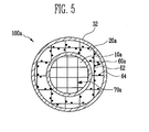
- FIG. 5 is a schematic cross-sectional view of a catalytic combustor according to another embodiment of the present invention.
- the cross-sectional view of FIG. 5 corresponds to a cross-sectional view taken along line II-II of FIG. 2 (or a corresponding cross-sectional view of the catalytic combustor of FIG. 1 ).
- the catalytic combustor 100a includes a housing 32 having a cylindrical first reaction portion 10a and a second reaction portion 20a surrounding the first reaction portion 10a in a double tube shape; a first catalyst layer (not shown) disposed in the first reaction portion 10a; a distributing portion 70a disposed at an upstream side of the first catalyst layer in the first reaction portion 10a; and a second catalyst layer 60a disposed in the second reaction portion 20a.
- the first and second reaction portions 10a and 20a of the housing 32 substantially have the same structures and shapes as the first and second reaction portions 10 and 20 illustrated in FIG. 2 , respectively.
- the first catalyst layer and the distributing portion 70a substantially have the same structures and shapes as the catalyst layer 50 and the distributing portion 70, illustrated in FIG. 2 , respectively.
- the second catalyst layer 60a is formed into a first-stage mesh layer and a second-stage mesh layer and a space is formed between the first-stage and the second-stage mesh layers in the same manner as the structure illustrated in FIG. 2 .
- the second catalyst layer 60a has a mesh layer 62 and an active material 64 coupled to the mesh layer 62.
- An amount (or a predetermined amount) of active material 64 is coupled to the mesh layer 62.
- the active material 64 may be coated at a density between about 0.01 and about 0.4g per 1 cc of the mesh layer 62.
- the active material 64 includes palladium and/or platinum. When the active material is coated at a lower density than that described above, the effect of fuel combustion caused by the active material is slight. When the active material is coated at a larger density than that described above, the use amount of a precious metal is increased, and therefore, manufacturing cost may be increased.
- the second catalyst layer 60a allows any suitable unburned fuel flowed out from the first reaction portion 10a to be secondarily oxidized.
- the unburned fuel is a fuel passing through the first catalyst layer without being oxidized by the first catalyst layer.
- FIG. 6 is a schematic perspective view of a catalytic combustor according to still another embodiment of the present invention.
- FIG. 7 is a schematic longitudinal sectional view of the catalytic combustor of FIG. 6 .
- the catalytic combustor 300 includes a housing 130 having first and second reaction portions 110 and 120, a first opening 131 for inflow of a first fuel to the first reaction portion 110, a second opening 133 for discharging the exhaust from second reaction portion 120; a catalyst layer 150 disposed in the first reaction portion 110; a mesh layer 160 disposed in the second reaction portion 120; and a fuel supply path 190 for supplying a second fuel between the first and second reaction portions 110 and 120.
- the housing 130 is formed in the shape of a cylinder having both closed ends.
- the hosing 130 includes a first housing having the cylindrical first reaction portion 110 formed therein and a second housing having the second reaction portion 120 formed between the first and second housings while surrounding the first reaction portion 100 in a double tube shape.
- the first and second reaction portions 110 and 120 are connected to each other so that a fluid is communicated with the first and second reaction portions 110 and 120 through a passage 135 positioned below the first and second reaction portions 110 and 120.
- first and second reaction portions 110 and 120 in the housing 130 are substantially identical to those of the first and second reaction portions 10 and 20 illustrated in FIG. 2 .
- a first point P1 indicates an upstream side or one end of the first reaction portion 110
- a second point P2 indicates a downstream side or the other end of the first reaction portion 110.
- the third point P3 indicates an upstream side or the other end of the second reaction portion 120
- a fourth point P4 indicates a downstream side or one end of the second reaction portion 120.
- the catalyst layer 150 is disposed closer to the downstream side than the upstream side of the first reaction portion 110.
- the structure and shape of the catalyst 150 is substantially identical to that of the catalyst layer 50 illustrated in FIG. 2 .
- the structure and shape of the mesh layer 160 is substantially identical to that of the mesh layer 60 illustrated in FIG. 2 .
- the mesh layer 160 has first and second mesh layers 161 a and 161 b with a two-stage structure.
- the first and second mesh layers 161 a and 161 b substantially have the same structures and shapes as the mesh layers 61 a and 61 b with a two-stage structure, illustrated in FIGS. 3 and 4 .
- the catalytic combustor 300 further includes a distributing portion 170 disposed in the first reaction portion 110.
- the structure and shape of the distributing portion 170 are substantially identical to those of the distributing portion 70 illustrated in FIG. 2 .
- the cross-sectional view taken along line III-III is substantially identical to that illustrated in FIG. 3 .
- the cross-sectional view taken along line IV-IV is substantially identical to that illustrated in FIG. 4 .
- the catalytic combustor 300 further includes a flashback arresting portion 180 disposed in the first reaction portion 110.
- the structure and shape of the flashback arresting portion 180 is substantially identical to that of the flashback arresting portion 80 illustrated in FIG. 2 .
- the fuel supply path 190 supplies the second fuel to the downstream side of the first reaction portion 110 or the upstream side of the second reaction portion 120.
- the second fuel is flowed into one end of the fuel supply path 190, and a third opening 137 of the housing 130 is formed at the one end of the fuel supply path 190.
- the other end 192 of the fuel supply path 190 is opened close to the second point P2.
- the second fuel may be a material more easily burned in the mesh layer 160 than the unburned fuel of the first fuel. Only an amount (or a predetermined amount) of the second fuel may be supplied. For example, when about 20L of combustible hydrocarbon (e.g., methane, butane or the like) expressed by a chemical formula of C m H 2n is supplied per hour, about 0.2 to 3L of the second fuel may be supplied per hour. If the supply amount of the second fuel is less than 1 % or exceeds 15% of the supply amount of the first fuel, the secondary oxidation efficiency of the unburned fuel is lowered due to the addition of the second fuel. Furthermore, if the supply amount of the second fuel exceeds 15% of the supply amount of the first fuel, the used amount of the entire fuel including the second fuel is increased, and therefore, its efficiency is lowered.
- combustible hydrocarbon e.g., methane, butane or the like
- the first fuel passes through the area of the catalyst layer 150 via the flashback arresting portion 180 and the distributing portion 170.
- the first fuel is oxidized in the catalyst layer 150.
- An unburned fuel in the first fuel is secondarily oxidized while passing through the mesh layer 160 together with a second fuel supplied at the downstream side of the first reaction portion 110 or the upstream side of the second reaction portion 120.
- the second fuel is a material more easily oxidized than an unburned fuel, the unburned fuel mixed with the second fuel is more effectively oxidized by the oxidation heat of the second fuel.
- a catalytic combustor according to still another embodiment of the present invention may be implemented so that the cross-sectional view taken along line IV-IV in the catalytic combustor of FIG. 7 includes components described in the cross-sectional view of FIG. 5 .
- the catalytic combustor according to this embodiment of the present invention may be substantially identical to the catalytic combustor 300 illustrated in FIGS. 6 and 7 , except that a second catalyst layer is provided in a second reaction portion.
- the second catalyst layer may be substantially identical to the second catalyst layer 60a of the catalytic combustor 100a illustrated in FIG. 5 .
- FIG. 8 is a schematic block diagram of a fuel cell system for describing an application of the catalytic combustor of FIG. 6 .
- the second fuel supplied to the catalytic combustor 300 includes an anode effluence exhausted from an anode of a fuel cell 500.
- the anode effluence may be used directly as the second fuel or used as a properly filtered gas containing hydrogen.
- the fuel cell 500 includes a power generating system for generating electricity and water through electrochemical reactions of a fuel (fourth fuel) and an oxidant.
- the fuel cell 500 may be one of various suitable fuel cells such as a polymer electrolyte membrane fuel cell (known in the art).
- the fourth fuel includes a reformate containing abundant hydrogen or a hydrocarbon-based fuel, and the oxidant includes oxygen in the air.
- the cathode effluence includes water.
- the catalytic combustors according to the embodiments of the present invention may be used to supply heat to a fuel reformer for supplying the fourth fuel to the fuel cell 500.
- a reforming reaction portion 400 is disposed between the first and second reaction portions 110 and 120 so that heat generated from the catalytic combustor 300 can be supplied to the reforming reaction portion 400.
- the reforming reaction portion 400 may include a steam reforming reaction portion for steam-reforming a third fuel to generate a reformate.
- the third fuel includes a hydrocarbon-based fuel.
- the reformate may be used as the fourth fuel of FIG. 8 .
Landscapes
- Chemical & Material Sciences (AREA)
- Engineering & Computer Science (AREA)
- Chemical Kinetics & Catalysis (AREA)
- Organic Chemistry (AREA)
- Combustion & Propulsion (AREA)
- Mechanical Engineering (AREA)
- General Engineering & Computer Science (AREA)
- Inorganic Chemistry (AREA)
- Health & Medical Sciences (AREA)
- General Health & Medical Sciences (AREA)
- Sustainable Development (AREA)
- Sustainable Energy (AREA)
- Electrochemistry (AREA)
- General Chemical & Material Sciences (AREA)
- Manufacturing & Machinery (AREA)
- Life Sciences & Earth Sciences (AREA)
- Hydrogen, Water And Hydrids (AREA)
- Catalysts (AREA)
- Fuel Cell (AREA)
Abstract
Description
- The following description relates to a catalytic combustor capable of inducing oxidation of a fuel and improving the thermal efficiency of a reactor, and a fuel reformer having the same.
- A combustor is a device that generates heat and high-temperature gas by oxidizing a fuel. The heat and high-temperature gas, generated from the combustor, may be used for reforming reaction of a reformer, preheating of fuel or water, and the like. The combustor may be manufactured in such a manner that allows a fuel sprayed into a combustion chamber to be directly burned, that allows a fuel to be burned through an oxidation catalyst, or the like. Here, in embodiments of the present invention, the device that allows a fuel to be oxidized through an oxidation catalyst is referred to as a catalytic combustor.
- A catalytic combustor allows a fuel to be burned (or oxidized) through contact with a catalyst at a lower operating temperature than that of a direct burning type combustor such as a burner. Therefore, in order to improve efficiency, the catalytic combustor is typically manufactured to have a faster space velocity than that in the direct combustor. In addition, the catalytic combustor is less expensive to operate and generates less nitrogen oxide than the direct burning type combustor.
- Also, the catalytic combustor allows a fuel to be burned at a relatively low temperature. However, in the catalytic combustor, it is difficult to allow a fuel to be completely burned as compared with the direct burning type combustor. If the fuel oxidation rate in the catalytic combustor is low, unburned fuel, carbon monoxide caused by partial oxidation of the unburned fuel and steam are contained in a large amount in an exhaust produced from the catalytic combustor.
- An aspect of the present invention is directed toward a catalytic combustor capable of inducing the complete oxidation of a fuel and improving the thermal efficiency of a reactor by utilizing a dual oxidation structure.
- Another aspect of the present invention is directed toward a catalytic combustor capable of inducing the complete oxidation of a fuel and improving the thermal efficiency of a reactor by utilizing a dual oxidation structure and a dual fuel structure.
- Another aspect of the present invention is directed toward a fuel reformer having the aforementioned catalytic combustor.
- According to an embodiment of the present invention, a catalytic combustor is provided. The catalytic combustor includes a housing having a cylindrical first reaction portion and a second reaction portion surrounding the first reaction portion in a double tube shape, the housing having a first opening for supplying a first fuel and an oxidant to the first reaction portion and a second opening through which an exhaust in the second reaction portion is discharged, the first and second openings being respectively disposed at first sides of the first and second reaction portions, and the first and second reaction portions being connected with each other at second sides of the first and second reaction portions so that the flow of a fluid in the first and second reaction portions forms a counter flow; a catalyst layer disposed in the first reaction portion; and a mesh layer inserted into the second reaction portion.
- In one embodiment, the catalyst layer is disposed at a rear-end portion of the first reaction portion and the mesh layer is disposed to be adjacent to the catalyst layer so that the mesh layer is accordingly heated by a heat energy from the first reaction portion.
- According to another embodiment of the present invention, there is provided a catalytic combustor which includes a housing having a cylindrical first reaction portion and a second reaction portion surrounding the first reaction portion in a double tube shape, the housing having a first opening for supplying a first fuel and an oxidant to the first reaction portion and a second opening through which an exhaust in the second reaction portion is discharged, the first and second openings being respectively disposed at first sides of the first and second reaction portions, and the first and second reaction portions being connected with each other at second sides of the first and second reaction portions so that the flow of a fluid in the first and second reaction portions forms a counter flow; a first catalyst layer disposed in the first reaction portion; and a second catalyst layer disposed in the second reaction portion.
- In one embodiment, the catalyst layer is disposed at a rear-end portion of the first reaction portion. The second catalyst layer may include a mesh layer and an active material coupled with the mesh layer. Further, the active material amount of the active material used in the second catalyst layer is less than that in the first catalyst layer. In one embodiment, the active material may be coated at a density between about 0.01 and 0.4g per 1cc of the mesh layer.
- According to still another embodiment of the present invention, there is provided a catalytic combustor which includes a housing having a cylindrical first reaction portion and a second reaction portion surrounding the first reaction portion in a double tube shape, the housing having a first opening for supplying a first fuel and an oxidant to the first reaction portion and a second opening through which an exhaust in the second reaction portion is discharged, the first and second openings being respectively disposed at first sides of the first and second reaction portions, and the first and second reaction portions being connected with each other at second sides of the first and second reaction portions so that the flow of a fluid in the first and second reaction portions forms a counter flow; a first catalyst layer disposed in the first reaction portion; a mesh layer disposed into the second reaction portion; and a fuel supply path for supplying a second fuel between the first and second reaction portions.
- In one embodiment, the catalyst layer is disposed at a rear-end portion of the first reaction portion and the mesh layer is disposed adjacent to the catalyst layer. In one embodiment, the fuel supply path is configured to supply the second fuel in an amount between about 1 and 15% of the supply amount of the first fuel. The second fuel may include an off gas containing hydrogen, exhausted from an anode of a fuel cell.
- According to still another embodiment of the present invention, there is provided a catalytic combustor which includes a housing having a cylindrical first reaction portion and a second reaction portion surrounding the first reaction portion in a double tube shape, the housing having a first opening for supplying a first fuel and an oxidant to the first reaction portion and a second opening through which an exhaust in the second reaction portion is discharged, the first and second openings being respectively disposed at first sides of the first and second reaction portions, and the first and second reaction portions being connected with each other at second sides of the first and second reaction portions so that the flow of a fluid in the first and second reaction portions forms a counter flow; a first catalyst layer disposed in the first reaction portion; a second catalyst layer disposed in the second reaction portion; and a fuel supply path for supplying a second fuel between the first and second reaction portions.
- In one embodiment, the first catalyst layer is disposed at a rear-end portion of the first reaction portion. The second catalyst layer may include a mesh layer and an active material coated on the mesh layer. Further, in one embodiment, the active material amount used in the second catalyst layer is less than that in the first catalyst layer. In one embodiment, the active material may be coated at a density between about 0.01 and 0.4g per 1cc of the mesh layer. In one embodiment, the fuel supply path is configured to supply the second fuel in an amount between about 1 and 15% of the supply amount of the first fuel. The second fuel may include an off gas containing hydrogen, exhausted from an anode of a fuel cell.
- The first catalyst may include a metallic honeycomb support having durability at a high temperature and an active material coupled with the support. In one embodiment, the cell density of the honeycomb support in the first catalyst layer may be between about 400 and about 600 cells per square inch.
- In one embodiment, the catalytic combustor may further include a distributing portion disposed at an upstream side of the first catalyst layer based on the flow of the fuel. The distributing portion may be formed of a metallic honeycomb monolith having durability at a high temperature. The space velocity of a fluid in the distributing portion may be faster than that of a fluid in the first catalyst layer. In one embodiment, the space velocity of the fluid in the first catalyst layer may be between about 1000 and about 50,000/hr. In another embodiment, the cell density of the honeycomb monolith in the distributing portion is less than that of the honeycomb support in the first catalyst layer. The cell density of the honeycomb monolith in the distributing portion may be between about 100 and about 200 cells per square inch.
- The catalytic combustor may further include a flashback arresting portion disposed at an upstream side of the distributing portion based on the flow of the fluid. The flashback arresting portion may be formed of a metallic honeycomb monolith having durability at a high temperature. The cell density of the honeycomb monolith in the flashback arresting portion may be the same as that of the honeycomb monolith in the distributing portion.
- The first catalyst layer and/or second catalyst layer may include palladium(Pd), platinum(Pt), Co3O4, PdO, Cr2O3, Mn2O3, CuO, Fe2O3, V2O3, NiO, MoO3, and/or TiO2.
- The mesh layer may be formed of a metallic honeycomb monolith having durability at a high temperature. The mesh layer may be formed into a two-stage structure. In one embodiment, the cell density of the honeycomb monolith in the mesh layer may be between about 50 and about 1000 cells per square inch.
- According to still another embodiment of the present invention, there is provided a fuel reformer which includes any one of the catalytic combustors according to the embodiments of the present invention; and a reforming reaction portion for generating a reformate by receiving heat energy generated from the catalytic combustor and for reforming a fuel.
- The above and other features of the invention are set out in the appended Claims.
- According to the embodiments of the present invention, a fuel is more completely oxidized in a catalytic combustor. Further, the catalytic combustor allows a thermal gradient to be uniform by using conduction and convection in the dual oxidation structure, so that hot spots are reduced. Accordingly, the thermal efficiency of the catalytic combustor can be considerably improved. Further, although an oxidation catalyst may be used only at a front end in the dual oxidation structure, i.e., a small amount of catalyst is used, the complete oxidation of a fuel can still be easily induced. Further, it is possible to improve the performance and efficiency of a fuel reformer having the catalytic combustor.
- The accompanying drawings, together with the specification, illustrate embodiments of the present invention, and, together with the description, serve to explain the principles of the present invention.
-
FIG. 1 is a schematic perspective view of a catalytic combustor according to an embodiment of the present invention. -
FIG. 2 is a schematic longitudinal sectional view of the catalytic combustor ofFIG. 1 . -
FIG. 3 is a schematic cross-sectional view of the catalytic combustor according to the embodiment ofFIG. 1 . -
FIG. 4 is another schematic cross-sectional view of the catalytic combustor according to the embodiment ofFIG. 1 . -
FIG. 5 is a schematic cross-sectional view of a catalytic combustor according to another embodiment of the present invention. -
FIG. 6 is a schematic perspective view of a catalytic combustor according to still another embodiment of the present invention. -
FIG. 7 is a schematic longitudinal sectional view of the catalytic combustor ofFIG. 6 . -
FIG. 8 is a schematic block diagram of a fuel cell system for describing an application of the catalytic combustor ofFIG. 6 . - In the following detailed description, only certain embodiments of the present invention have been shown and described, simply by way of illustration. As those skilled in the art would realize, the described embodiments may be modified in various different ways, all without departing from the scope of the present invention. Accordingly, the drawings and description are to be regarded as illustrative in nature and not restrictive. In addition, when an element is referred to as being "on" another element, it can be directly on the another element or be indirectly on the another element with one or more intervening elements interposed therebetween. Also, when an element is referred to as being "connected to" another element, it can be directly connected to the another element or be indirectly connected to the another element with one or more intervening elements interposed therebetween. Hereinafter, like reference numerals refer to like elements. In the drawings, the thicknesses and sizes of elements are exaggerated for clarity.
-
FIG. 1 is a schematic perspective view of a catalytic combustor according to an embodiment of the present invention.FIG. 2 is a schematic longitudinal sectional view of the catalytic combustor ofFIG. 1 .FIG. 3 is a schematic cross-sectional view of the catalytic combustor according to the embodiment of the present invention. The cross-sectional view ofFIG. 3 corresponds to a cross-sectional view taken along line I-I ofFIG. 2 (or a corresponding cross-sectional view of the catalytic combustor ofFIG. 1 ).FIG. 4 is another schematic cross-sectional view of the catalytic combustor according to the embodiment of the present invention. The cross-sectional view ofFIG. 4 corresponds to a cross-sectional view taken along line II-II ofFIG. 2 (or a corresponding cross-sectional view of the catalytic combustor ofFIG. 1 ). - Referring to
FIGS. 1 and2 , thecatalytic combustor 100 includes ahousing 30 having first andsecond reactor portions catalyst layer 50 disposed in thefirst reaction portion 10; and amesh layer 60 disposed in thesecond reaction portion 20. - The
housing 30 includes afirst housing 30a having thefirst reaction portion 10 formed therein and asecond housing 30b having thesecond reaction portion 20 formed between the first andsecond housings first reaction portion 10 in a double tube shape. In an embodiment of the present invention as shown, both ends of the tubular orcylindrical housing 30 are substantially closed. - The
housing 30 has at least onefirst opening 31 and at least onesecond opening 33. Thefirst opening 31 serves as a passage through which a fuel (or first fuel) is supplied to thefirst reaction portion 10. Thefirst opening 31 is formed at one side in the length direction of thecylindrical housing 30. Thesecond opening 33 serves as a passage through which an exhaust in thesecond reaction portion 20 is discharged to the exterior of thehousing 30. Thesecond opening 33 is formed at one side in the length direction of thecylindrical housing 30. The first andsecond openings housing 30. - The
cylindrical housing 30 has apassage 35 formed at the other side in the length direction of thehousing 30. The other side is the opposite side to the one side. Thepassage 35 allows the first andsecond reaction portions second reaction portions second reaction portions catalytic combustor 100 through thesecond opening 33 provided at the downstream side of thesecond reaction portion 20. - In other words, the
first opening 31 is connected to one end of the first reaction portion 10 (e.g., an upstream side of thefirst reaction portion 10 based on the flow of a fluid in the catalytic combustor 100), and one end of thepassage 35 is connected to the other end of the first reaction portion 10 (e.g., the downstream side based on the flow of thefirst reaction portion 10 of the fluid in the catalytic combustor 100). The other end of thepassage 35 is connected to the other end of the second reaction portion 20 (e.g., the upstream side of thesecond reaction portion 20 based on the flow of the fluid in the catalytic combustor 100), and thesecond opening 33 is connected to one end of the second reaction portion 20 (e.g., the downstream side of thesecond reaction portion 20 based on the flow of the fluid in the catalytic combustor 100). That is, thehousing 30 has the first andsecond reaction portions housing 30 flows backward. This structure is referred to as a dual oxidation structure in embodiments of the present invention. - The
catalyst layer 50 is disposed at a rear-end portion of thefirst reaction portion 10. In other words, when thefirst reaction portion 10 is approximately divided into a first area A1 positioned at the upstream side on the flow of the fuel and a second area A2 positioned at the downstream side on the flow of the fuel, thecatalyst layer 50 is disposed in the second area A2. - As illustrated in
FIG. 3 , thecatalyst layer 50 includes a metallic orceramic honeycomb support 52 and anactive material 54 coupled with thesupport 52. Theactive material 54 may include platinum, palladium, and/or another precious metal. For example, in one embodiment, thecatalyst layer 50 includes Pd, Pt, Co3O4, PdO, Cr2O3, Mn2O3, CuO, Fe2O3, V2O3, NiO, MoO3 and/or TiO2. - The
mesh layer 60 is disposed at a front-end portion of the second reaction portion 20 (adjacent to the rear-end portion at which thecatalyst layer 50 is disposed) so that an unburned fuel from thefirst reaction portion 10 is well oxidized. For example, themesh layer 60 may be formed of a metallic honeycomb monolith having durability at a high temperature. The unburned fuel is oxidized when in contact with themetallic mesh layer 60 and heated to about 150 to 400°C in a reaction within thecatalytic combustor 100. By employing themesh layer 60 to be disposed to be adjacent to thecatalyst layer 50, the fuel is oxidized twice, and accordingly, the complete oxidation of the fuel can be induced. - Furthermore, in this embodiment, the
mesh layer 60 is formed into a first-stage mesh layer 61 a and a second-stage mesh layer 61 b based on the flow of a fluid in thesecond reaction portion 20. By employing the mesh layers 61 a and 61 b with a two-stage structure, a turbulent flow is formed in the flow of the unburned fuel at aspace 63 between the first-stage mesh layer 61 a and the second-stage mesh layer 61 b, so that the entire unburned fuel passing through themesh layer 60 can be more completely oxidized and in contact with themesh layer 60. - The
catalytic combustor 100 according to this embodiment of the present invention further includes a distributingportion 70 disposed at a front-end portion of thefirst reaction portion 10. The distributingportion 70 is disposed at the upstream side of thecatalyst layer 50 on the flow of the fuel. The distributingportion 70 appropriately distributes a fuel flowing into thefirst reaction portion 10 and sends the distributed fuel to thecatalyst layer 50. By employing the distributingportion 70, it is possible to prevent or reduce large hot spots from being generated by the oxidation of the fuel concentrated on a specific point at the one end (i.e., at the upstream side) of thecatalyst layer 50. - The distributing
portion 70 is configured in accordance with thecatalyst layer 50. The distributingportion 70 is formed of a metallic honeycomb monolith having durability at a high temperature, as illustrated inFIG. 4 . That is, in the interior of thefirst reaction portion 10, the space velocity of a fluid flowing in the distributingportion 70 is faster than that in thecatalyst layer 50. For example, the space velocity in thecatalyst layer 50 may be between about 1000 and about 50,000/hr. In other words, the cell density in the honeycomb monolith of the distributingportion 70 is formed less than that in thehoneycomb support 52 of thecatalyst layer 50. For example, the cell density in the honeycomb monolith of the distributingportion 70 may be between about 100 and about 200 cells per square inch. - Referring to
FIG. 2 again, thecatalytic combustor 100 according to this embodiment of the present invention includes aflashback arresting portion 80 disposed in the front-end portion of thefirst reaction portion 10. Theflashback arresting portion 80 is disposed at an upstream side of thecatalyst layer 50 and/or the distributingportion 70. Theflashback arresting portion 80 prevents or reduces a spark generated in thecatalyst layer 50 from being spread toward thefirst opening 31. - The
flashback arresting portion 80 may be formed of a metallic honeycomb monolith having durability at a high temperature. Theflashback arresting portion 80 is configured in accordance with thecatalyst layer 50 and/or the distributingportion 70. For example, in one embodiment, theflashback arresting portion 80 has the same cell density and/or sectional structure (or sectional shape) as the distributingportion 70. The length of theflashback arresting portion 80 may be different from that of the distributingportion 70 along the flow direction of the fluid flowing in the interior of thefirst reaction portion 10. - In an embodiment of the present invention, a fuel and an oxidizer may be individually supplied through a plurality of first openings. The fuel includes a hydrocarbon-based fuel such as methane, butane and/or propane. The oxidant includes air.
- According to the aforementioned configuration, when a first fuel and an oxidant are flowed into the
first reaction portion 10 through thefirst opening 31, the first fuel passes through the area of thecatalyst layer 50 via theflashback arresting portion 80 and the distributingportion 70. In this case, the first fuel is oxidized in thecatalyst layer 50 and any unburned fuel not oxidized in thecatalyst layer 50 is secondarily oxidized while passing through themesh layer 60. - Accordingly, the
catalytic combustor 100 allows a thermal gradient to be uniform by using conduction and convection in the dual oxidation structure, so that hot spots can be reduced. Further, the complete oxidation of a fuel can be promoted by utilizing an oxidation catalyst only in the front-stage portion (that is, the first reaction portion) in the dual oxidation structure, so that manufacturing cost may be reduced. -
FIG. 5 is a schematic cross-sectional view of a catalytic combustor according to another embodiment of the present invention. The cross-sectional view ofFIG. 5 corresponds to a cross-sectional view taken along line II-II ofFIG. 2 (or a corresponding cross-sectional view of the catalytic combustor ofFIG. 1 ). - Referring to
FIG. 5 , thecatalytic combustor 100a according to this further embodiment of the present invention includes ahousing 32 having a cylindricalfirst reaction portion 10a and asecond reaction portion 20a surrounding thefirst reaction portion 10a in a double tube shape; a first catalyst layer (not shown) disposed in thefirst reaction portion 10a; a distributingportion 70a disposed at an upstream side of the first catalyst layer in thefirst reaction portion 10a; and asecond catalyst layer 60a disposed in thesecond reaction portion 20a. - The first and
second reaction portions housing 32 substantially have the same structures and shapes as the first andsecond reaction portions FIG. 2 , respectively. - The first catalyst layer and the distributing
portion 70a substantially have the same structures and shapes as thecatalyst layer 50 and the distributingportion 70, illustrated inFIG. 2 , respectively. - The
second catalyst layer 60a is formed into a first-stage mesh layer and a second-stage mesh layer and a space is formed between the first-stage and the second-stage mesh layers in the same manner as the structure illustrated inFIG. 2 . - In this embodiment, the
second catalyst layer 60a has amesh layer 62 and anactive material 64 coupled to themesh layer 62. An amount (or a predetermined amount) ofactive material 64 is coupled to themesh layer 62. For example, theactive material 64 may be coated at a density between about 0.01 and about 0.4g per 1 cc of themesh layer 62. Theactive material 64 includes palladium and/or platinum. When the active material is coated at a lower density than that described above, the effect of fuel combustion caused by the active material is slight. When the active material is coated at a larger density than that described above, the use amount of a precious metal is increased, and therefore, manufacturing cost may be increased. - In this embodiment of the present invention, the
second catalyst layer 60a allows any suitable unburned fuel flowed out from thefirst reaction portion 10a to be secondarily oxidized. Here, the unburned fuel is a fuel passing through the first catalyst layer without being oxidized by the first catalyst layer. By employing the dual oxidation structure together with a small active material for promoting oxidation of the unburned fuel, the fuel can be oxidized (or completely oxidized) more effectively than in the embodiment described with reference toFIG. 2 (that is, the embodiment in which only themesh layer 60 is disposed in the second reaction portion 20). -
FIG. 6 is a schematic perspective view of a catalytic combustor according to still another embodiment of the present invention.FIG. 7 is a schematic longitudinal sectional view of the catalytic combustor ofFIG. 6 . - Referring to
FIGS. 6 and7 , thecatalytic combustor 300 includes ahousing 130 having first andsecond reaction portions first opening 131 for inflow of a first fuel to thefirst reaction portion 110, asecond opening 133 for discharging the exhaust fromsecond reaction portion 120; acatalyst layer 150 disposed in thefirst reaction portion 110; amesh layer 160 disposed in thesecond reaction portion 120; and afuel supply path 190 for supplying a second fuel between the first andsecond reaction portions - The
housing 130 is formed in the shape of a cylinder having both closed ends. The hosing 130 includes a first housing having the cylindricalfirst reaction portion 110 formed therein and a second housing having thesecond reaction portion 120 formed between the first and second housings while surrounding thefirst reaction portion 100 in a double tube shape. When the length directions of the first andsecond reaction portions second reaction portions second reaction portions passage 135 positioned below the first andsecond reaction portions - In the embodiment of
FIGS. 6 and7 , the structures and shapes of the first andsecond reaction portions housing 130 are substantially identical to those of the first andsecond reaction portions FIG. 2 . For reference, inFIG. 7 , a first point P1 indicates an upstream side or one end of thefirst reaction portion 110, and a second point P2 indicates a downstream side or the other end of thefirst reaction portion 110. InFIG. 7 , the third point P3 indicates an upstream side or the other end of thesecond reaction portion 120, and a fourth point P4 indicates a downstream side or one end of thesecond reaction portion 120. - The
catalyst layer 150 is disposed closer to the downstream side than the upstream side of thefirst reaction portion 110. The structure and shape of thecatalyst 150 is substantially identical to that of thecatalyst layer 50 illustrated inFIG. 2 . - The structure and shape of the
mesh layer 160 is substantially identical to that of themesh layer 60 illustrated inFIG. 2 . Themesh layer 160 has first and second mesh layers 161 a and 161 b with a two-stage structure. In this case, the first and second mesh layers 161 a and 161 b substantially have the same structures and shapes as the mesh layers 61 a and 61 b with a two-stage structure, illustrated inFIGS. 3 and 4 . - The
catalytic combustor 300 according to this embodiment of the present invention further includes a distributingportion 170 disposed in thefirst reaction portion 110. The structure and shape of the distributingportion 170 are substantially identical to those of the distributingportion 70 illustrated inFIG. 2 . - In the
catalytic combustor 300 according to this embodiment of the present invention, the cross-sectional view taken along line III-III is substantially identical to that illustrated inFIG. 3 . In thecatalytic combustor 300 according to this embodiment of the present invention, the cross-sectional view taken along line IV-IV is substantially identical to that illustrated inFIG. 4 . - The
catalytic combustor 300 according to this embodiment of the present invention further includes aflashback arresting portion 180 disposed in thefirst reaction portion 110. The structure and shape of theflashback arresting portion 180 is substantially identical to that of theflashback arresting portion 80 illustrated inFIG. 2 . - The
fuel supply path 190 supplies the second fuel to the downstream side of thefirst reaction portion 110 or the upstream side of thesecond reaction portion 120. The second fuel is flowed into one end of thefuel supply path 190, and athird opening 137 of thehousing 130 is formed at the one end of thefuel supply path 190. Theother end 192 of thefuel supply path 190 is opened close to the second point P2. - In one embodiment, the second fuel may be a material more easily burned in the
mesh layer 160 than the unburned fuel of the first fuel. Only an amount (or a predetermined amount) of the second fuel may be supplied. For example, when about 20L of combustible hydrocarbon (e.g., methane, butane or the like) expressed by a chemical formula of CmH2n is supplied per hour, about 0.2 to 3L of the second fuel may be supplied per hour. If the supply amount of the second fuel is less than 1 % or exceeds 15% of the supply amount of the first fuel, the secondary oxidation efficiency of the unburned fuel is lowered due to the addition of the second fuel. Furthermore, if the supply amount of the second fuel exceeds 15% of the supply amount of the first fuel, the used amount of the entire fuel including the second fuel is increased, and therefore, its efficiency is lowered. - When combustible hydrocarbons are used as the first and/or second fuel, the combustion reaction formula of the fuel in the catalytic combustor is as follows.
CmH2n + (m+2n)O2 → mCO2 + nH2O + calorie ......(1)
- According to the aforementioned configuration, when a first fuel and an oxidant are flowed into the
first reaction portion 110 through thefirst opening 131, the first fuel passes through the area of thecatalyst layer 150 via theflashback arresting portion 180 and the distributingportion 170. In this case, the first fuel is oxidized in thecatalyst layer 150. An unburned fuel in the first fuel is secondarily oxidized while passing through themesh layer 160 together with a second fuel supplied at the downstream side of thefirst reaction portion 110 or the upstream side of thesecond reaction portion 120. Here, if the second fuel is a material more easily oxidized than an unburned fuel, the unburned fuel mixed with the second fuel is more effectively oxidized by the oxidation heat of the second fuel. - In addition, a catalytic combustor according to still another embodiment of the present invention may be implemented so that the cross-sectional view taken along line IV-IV in the catalytic combustor of
FIG. 7 includes components described in the cross-sectional view ofFIG. 5 . - In other words, the catalytic combustor according to this embodiment of the present invention may be substantially identical to the
catalytic combustor 300 illustrated inFIGS. 6 and7 , except that a second catalyst layer is provided in a second reaction portion. The second catalyst layer may be substantially identical to thesecond catalyst layer 60a of thecatalytic combustor 100a illustrated inFIG. 5 . -
FIG. 8 is a schematic block diagram of a fuel cell system for describing an application of the catalytic combustor ofFIG. 6 . - Referring to
FIG. 8 , the second fuel supplied to thecatalytic combustor 300 according to an embodiment of the present invention includes an anode effluence exhausted from an anode of afuel cell 500. The anode effluence may be used directly as the second fuel or used as a properly filtered gas containing hydrogen. - The
fuel cell 500 includes a power generating system for generating electricity and water through electrochemical reactions of a fuel (fourth fuel) and an oxidant. Thefuel cell 500 may be one of various suitable fuel cells such as a polymer electrolyte membrane fuel cell (known in the art). The fourth fuel includes a reformate containing abundant hydrogen or a hydrocarbon-based fuel, and the oxidant includes oxygen in the air. The cathode effluence includes water. - In addition, the catalytic combustors according to the embodiments of the present invention may be used to supply heat to a fuel reformer for supplying the fourth fuel to the
fuel cell 500. For example, as illustrated inFIG. 7 , a reformingreaction portion 400 is disposed between the first andsecond reaction portions catalytic combustor 300 can be supplied to the reformingreaction portion 400. The reformingreaction portion 400 may include a steam reforming reaction portion for steam-reforming a third fuel to generate a reformate. The third fuel includes a hydrocarbon-based fuel. The reformate may be used as the fourth fuel ofFIG. 8 . - The detailed structure and shape of the reforming
reaction portion 400 is well known by those skilled in the art. Therefore, detailed description of the reformingreaction portion 400 will not be provided. - While the present invention has been described in connection with certain exemplary embodiments, it is to be understood that the invention is not limited to the disclosed embodiments, but, on the contrary, is intended to cover various modifications and equivalent arrangements included within the scope of the appended claims, and equivalents thereof.
Claims (15)
- A catalytic combustor comprising:a housing having a cylindrical first reaction portion and a second reaction portion surrounding the first reaction portion in a double tube shape, the housing having a first opening for supplying a first fuel and an oxidant to the first reaction portion and a second opening for discharging an exhaust from the second reaction portion, the first and second openings being in a first end region of the first and second reaction portions, and the first and second reaction portions being connected with each other in a second end region of the first and second reaction portions so that the flow of a fluid in the first and second reaction portions forms a counter flow;a catalyst layer in the first reaction portion; anda mesh layer in the second reaction portion;wherein the catalyst layer is situated in a downstream portion of the first reaction portion.
- A catalytic combustor according to claim 1, wherein the catalyst layer comprises a honeycomb support and an active material coupled with the support.
- A catalytic combustor according to claim 1 or 2, further comprising a distributing portion at an upstream side of the catalyst layer based on the flow of the fuel.
- A catalytic combustor according to claim 3, wherein the distributing portion comprises a honeycomb monolith configured to pass a fluid with a space velocity faster than that of a fluid in the catalyst layer.
- A catalytic combustor according to claim 4, wherein a cell density of the honeycomb monolith in the distributing portion is less than that of the honeycomb support in the catalyst layer.
- A catalytic combustor according to any of claims 3 to 8, further comprising a flashback arresting portion at an upstream side of the distributing portion based on the flow of the fluid.
- A catalytic combustor according to claim 6, wherein the flashback arresting portion comprises a honeycomb monolith, and a cell density of the honeycomb monolith in the flashback arresting portion is substantially identical to that of the honeycomb monolith in the distributing portion.
- A catalytic combustor according to claim 1, wherein the mesh layer comprises a metallic honeycomb monolith and has a two-stage structure.
- A catalytic combustor according to claim 8, wherein a cell density of the honeycomb monolith in the mesh layer is from 50 to 1000 cells per square inch.
- A catalytic combustor according to any preceding claim, further comprising a fuel supply path for supplying a second fuel between the first and second reaction portions.
- The catalytic combustor according to claim 10, wherein the second fuel comprises an off gas containing hydrogen, discharged from an anode of a fuel cell.
- A catalytic according to any preceding claim, wherein the mesh layer comprises a catalyst.
- A catalytic combustor according to claim 12, wherein an active material is coupled with the mesh layer, and the amount of the active material in the mesh layer is less than that in the first catalyst layer.
- A catalytic combustor according to claim 13, wherein the active material of the mesh layer is coated at a density of from 0.01 to 0.4g per 1cc of the mesh layer.
- A fuel reformer comprising:a catalytic combustor; anda reforming reaction portion for generating a reformate by receiving heat energy generated from the catalytic combustor and for reforming a fuel,wherein the catalytic combustor is as set out in any preceding claim.
Applications Claiming Priority (1)
| Application Number | Priority Date | Filing Date | Title |
|---|---|---|---|
| KR1020090046894A KR101040885B1 (en) | 2009-05-28 | 2009-05-28 | Catalytic Combustor and Fuel Reformer With The Same |
Publications (2)
| Publication Number | Publication Date |
|---|---|
| EP2255872A2 true EP2255872A2 (en) | 2010-12-01 |
| EP2255872A3 EP2255872A3 (en) | 2011-05-25 |
Family
ID=42671714
Family Applications (1)
| Application Number | Title | Priority Date | Filing Date |
|---|---|---|---|
| EP10250127A Withdrawn EP2255872A3 (en) | 2009-05-28 | 2010-01-26 | Catalytic combustor and fuel reformer having the same |
Country Status (5)
| Country | Link |
|---|---|
| US (1) | US8617269B2 (en) |
| EP (1) | EP2255872A3 (en) |
| JP (1) | JP5181155B2 (en) |
| KR (1) | KR101040885B1 (en) |
| CN (1) | CN101900329B (en) |
Cited By (3)
| Publication number | Priority date | Publication date | Assignee | Title |
|---|---|---|---|---|
| EP2515038A1 (en) * | 2011-04-21 | 2012-10-24 | Nederlandse Organisatie voor toegepast -natuurwetenschappelijk onderzoek TNO | Fixed bed chemical looping combustion |
| WO2018069837A1 (en) * | 2016-10-10 | 2018-04-19 | King Abdullah University Of Science And Technology | Burners for conversion of methane to olefins, aromatics, and nanoparticles |
| CN111288490A (en) * | 2020-03-23 | 2020-06-16 | 上海电力大学 | Combustion chamber device of high-temperature backflow zone at scattered boss |
Families Citing this family (10)
| Publication number | Priority date | Publication date | Assignee | Title |
|---|---|---|---|---|
| CN102147111B (en) * | 2011-03-21 | 2012-06-06 | 重庆大学 | Grading catalytic combustion device capable of coupling strong and weak heat release |
| US20130195736A1 (en) * | 2012-02-01 | 2013-08-01 | Delphi Technologies, Inc. | Heat exchanger reformer |
| SE536578C2 (en) * | 2012-05-15 | 2014-03-04 | Reformtech Heating Holding Ab | Fuel injection system for use in a catalytic heater and reactor for conducting catalytic combustion liquid fuels |
| CN103486578B (en) * | 2013-09-16 | 2015-12-09 | 云南天安化工有限公司 | The device and method of the tail gas catalyzed burning of a kind of liquid nitrogen washing |
| DE102013114852B4 (en) | 2013-12-23 | 2018-07-05 | Aalto University | Arrangement and method for carrying out an intensified combustion |
| CN108232252B (en) * | 2016-12-15 | 2020-02-21 | 中国科学院大连化学物理研究所 | A catalytic burner and its application |
| DK180247B1 (en) | 2018-11-20 | 2020-09-14 | Blue World Technologies Holding ApS | Fuel cell system, its use and method of its operation |
| KR20210092787A (en) | 2018-11-20 | 2021-07-26 | 블루 월드 테크놀로지스 홀딩 에이피에스 | Fuel cell system, use thereof and method of operation thereof |
| RU195265U1 (en) * | 2018-12-13 | 2020-01-21 | Федеральное государственное бюджетное учреждение науки "Федеральный исследовательский центр "Институт катализа им. Г.К. Борескова Сибирского отделения Российской академии наук" (Институт катализа СО РАН, ИК СО РАН) | CATALYTIC HEAT GENERATOR |
| KR20230146245A (en) * | 2022-04-12 | 2023-10-19 | 주식회사 에코마스터 | Catalytic combustor for fuel cell system off-gas and fuel cell apparatus including the same |
Citations (1)
| Publication number | Priority date | Publication date | Assignee | Title |
|---|---|---|---|---|
| EP1394103A1 (en) * | 2001-06-04 | 2004-03-03 | Tokyo Gas Company Limited | Cylindrical water vapor reforming unit |
Family Cites Families (30)
| Publication number | Priority date | Publication date | Assignee | Title |
|---|---|---|---|---|
| GB2268694A (en) | 1992-07-14 | 1994-01-19 | Rolls Royce Plc | A catalytic combustion chamber |
| JPH06337104A (en) * | 1993-05-27 | 1994-12-06 | Toshiba Corp | Catalytic combustion device |
| JPH07126002A (en) | 1993-10-29 | 1995-05-16 | Aqueous Res:Kk | Fuel reformer |
| JP3375790B2 (en) * | 1995-06-23 | 2003-02-10 | 日本碍子株式会社 | Exhaust gas purification system and exhaust gas purification method |
| JP3767104B2 (en) * | 1997-07-17 | 2006-04-19 | 株式会社デンソー | Catalytic combustion device |
| US6065957A (en) * | 1996-03-21 | 2000-05-23 | Denso Corporation | Catalyst combustion apparatus |
| JPH10167701A (en) | 1996-12-13 | 1998-06-23 | Matsushita Electric Ind Co Ltd | Reformer |
| DE19721630C1 (en) * | 1997-05-23 | 1999-02-11 | Fraunhofer Ges Forschung | Device for reforming hydrocarbons containing starting materials |
| JP3858481B2 (en) * | 1998-11-10 | 2006-12-13 | 松下電器産業株式会社 | Catalytic combustor |
| JP3572395B2 (en) * | 2000-02-18 | 2004-09-29 | 日産自動車株式会社 | Combustor for fuel reformer |
| JP4155692B2 (en) * | 2000-03-10 | 2008-09-24 | 大阪瓦斯株式会社 | Hybrid catalytic combustion device |
| JP4029575B2 (en) | 2001-01-30 | 2008-01-09 | スズキ株式会社 | Fuel reformer |
| JP4747469B2 (en) * | 2001-09-10 | 2011-08-17 | トヨタ自動車株式会社 | Combustion device |
| US7037349B2 (en) * | 2002-06-24 | 2006-05-02 | Delphi Technologies, Inc. | Method and apparatus for fuel/air preparation in a fuel cell |
| DE10234043A1 (en) | 2002-07-26 | 2004-02-05 | Forschungszentrum Karlsruhe Gmbh | Microstructure apparatus for heating a fluid |
| US6936238B2 (en) * | 2002-09-06 | 2005-08-30 | General Motors Corporation | Compact partial oxidation/steam reactor with integrated air preheater, fuel and water vaporizer |
| US7862631B2 (en) * | 2003-02-07 | 2011-01-04 | Gm Global Technology Operations, Inc. | Fuel processor primary reactor and combustor startup via electrically-heated catalyst |
| US6932958B2 (en) * | 2003-03-26 | 2005-08-23 | Gas Technology Institute | Simplified three-stage fuel processor |
| WO2005000737A1 (en) * | 2003-06-27 | 2005-01-06 | Ebara Ballard Corporation | Fuel reformer |
| JP2005195254A (en) * | 2004-01-07 | 2005-07-21 | Ishikawajima Harima Heavy Ind Co Ltd | Catalytic combustor for fuel cell power generator |
| KR100551053B1 (en) * | 2004-06-29 | 2006-02-09 | 삼성에스디아이 주식회사 | Reformer of fuel cell system and fuel cell system employing same |
| KR100551036B1 (en) * | 2004-06-30 | 2006-02-13 | 삼성에스디아이 주식회사 | Reformer of fuel cell system and fuel cell system employing same |
| KR100570697B1 (en) | 2004-09-24 | 2006-04-12 | 삼성에스디아이 주식회사 | Fuel cell system and reformer used therein |
| JP2006349257A (en) * | 2005-06-16 | 2006-12-28 | Orion Mach Co Ltd | Combustion device and hot air generator |
| KR100684771B1 (en) | 2005-09-27 | 2007-02-20 | 삼성에스디아이 주식회사 | Fuel reformer and driving method thereof |
| KR100814888B1 (en) | 2007-04-13 | 2008-03-18 | 삼성에스디아이 주식회사 | Oxidation reactor, reforming apparatus comprising the same, and a driving method thereof |
| KR100823515B1 (en) | 2007-04-24 | 2008-04-21 | 삼성에스디아이 주식회사 | Fuel reformer and driving method thereof |
| CN101790662A (en) * | 2007-08-28 | 2010-07-28 | 奥格尔斯比&巴特勒研究与发展有限公司 | Gas-powered heating unit and heated, non-combustible evaporation apparatus |
| KR101008402B1 (en) * | 2008-12-19 | 2011-01-14 | 삼성에스디아이 주식회사 | Reformer |
| KR101001395B1 (en) * | 2009-03-03 | 2010-12-14 | 삼성에스디아이 주식회사 | Fuel reformer |
-
2009
- 2009-05-28 KR KR1020090046894A patent/KR101040885B1/en not_active Expired - Fee Related
- 2009-09-24 JP JP2009219174A patent/JP5181155B2/en not_active Expired - Fee Related
- 2009-11-10 US US12/616,115 patent/US8617269B2/en not_active Expired - Fee Related
- 2009-12-04 CN CN2009102528514A patent/CN101900329B/en not_active Expired - Fee Related
-
2010
- 2010-01-26 EP EP10250127A patent/EP2255872A3/en not_active Withdrawn
Patent Citations (1)
| Publication number | Priority date | Publication date | Assignee | Title |
|---|---|---|---|---|
| EP1394103A1 (en) * | 2001-06-04 | 2004-03-03 | Tokyo Gas Company Limited | Cylindrical water vapor reforming unit |
Cited By (5)
| Publication number | Priority date | Publication date | Assignee | Title |
|---|---|---|---|---|
| EP2515038A1 (en) * | 2011-04-21 | 2012-10-24 | Nederlandse Organisatie voor toegepast -natuurwetenschappelijk onderzoek TNO | Fixed bed chemical looping combustion |
| WO2012144897A1 (en) * | 2011-04-21 | 2012-10-26 | Nederlandse Organisatie Voor Toegepast-Natuurwetenschappelijk Onderzoek Tno | Fixed bed chemical looping combustion |
| WO2018069837A1 (en) * | 2016-10-10 | 2018-04-19 | King Abdullah University Of Science And Technology | Burners for conversion of methane to olefins, aromatics, and nanoparticles |
| US11175035B2 (en) | 2016-10-10 | 2021-11-16 | King Abdullah University Of Science And Technology | Burners for conversion of methane to olefins, aromatics, and nanoparticles |
| CN111288490A (en) * | 2020-03-23 | 2020-06-16 | 上海电力大学 | Combustion chamber device of high-temperature backflow zone at scattered boss |
Also Published As
| Publication number | Publication date |
|---|---|
| KR101040885B1 (en) | 2011-06-16 |
| KR20100128483A (en) | 2010-12-08 |
| CN101900329A (en) | 2010-12-01 |
| US20100303681A1 (en) | 2010-12-02 |
| EP2255872A3 (en) | 2011-05-25 |
| JP5181155B2 (en) | 2013-04-10 |
| JP2010276331A (en) | 2010-12-09 |
| US8617269B2 (en) | 2013-12-31 |
| CN101900329B (en) | 2012-07-18 |
Similar Documents
| Publication | Publication Date | Title |
|---|---|---|
| US8617269B2 (en) | Catalytic combustor and fuel reformer having the same | |
| US7025903B2 (en) | Reformer system process | |
| US7862631B2 (en) | Fuel processor primary reactor and combustor startup via electrically-heated catalyst | |
| US20110146154A1 (en) | Gas generator and processes for the conversion of a fuel into an oxygen-depleted gas and/or hydrogen-enriched gas | |
| JP5152811B2 (en) | Reformer | |
| EP2810329B1 (en) | Fuel cell module | |
| CN107925105B (en) | Solid oxide fuel cell system | |
| EP2158962B1 (en) | Method for forming a fuel cell reformer | |
| JP2009093923A (en) | Solid oxide fuel cell module | |
| EP2407224B1 (en) | Catalytic Combustor for a Reformer for a Fuel Cell | |
| JP2005213133A (en) | Reformer and fuel cell system | |
| US8690976B2 (en) | Fuel reformer | |
| US8017088B2 (en) | Fuel reformer | |
| JP5658897B2 (en) | Reforming apparatus and fuel cell system | |
| JP5659329B2 (en) | Auxiliary fuel cell and fuel cell | |
| JP5448985B2 (en) | Auxiliary device for solid oxide fuel cell, solid oxide fuel cell, and solid oxide fuel cell system | |
| JP4945901B2 (en) | Operation method of fuel cell power generation system | |
| JP6635853B2 (en) | Fuel cell system | |
| JP5627942B2 (en) | Solid oxide fuel cell device and combustor for solid oxide fuel cell stack | |
| JP2007323904A (en) | Solid oxide fuel cell module and starting method thereof | |
| KR20070102313A (en) | Reformer and fuel cell system using same |
Legal Events
| Date | Code | Title | Description |
|---|---|---|---|
| PUAI | Public reference made under article 153(3) epc to a published international application that has entered the european phase |
Free format text: ORIGINAL CODE: 0009012 |
|
| 17P | Request for examination filed |
Effective date: 20100202 |
|
| AK | Designated contracting states |
Kind code of ref document: A2 Designated state(s): AT BE BG CH CY CZ DE DK EE ES FI FR GB GR HR HU IE IS IT LI LT LU LV MC MK MT NL NO PL PT RO SE SI SK SM TR |
|
| AX | Request for extension of the european patent |
Extension state: AL BA RS |
|
| PUAL | Search report despatched |
Free format text: ORIGINAL CODE: 0009013 |
|
| AK | Designated contracting states |
Kind code of ref document: A3 Designated state(s): AT BE BG CH CY CZ DE DK EE ES FI FR GB GR HR HU IE IS IT LI LT LU LV MC MK MT NL NO PL PT RO SE SI SK SM TR |
|
| AX | Request for extension of the european patent |
Extension state: AL BA RS |
|
| 17Q | First examination report despatched |
Effective date: 20130729 |
|
| STAA | Information on the status of an ep patent application or granted ep patent |
Free format text: STATUS: THE APPLICATION IS DEEMED TO BE WITHDRAWN |
|
| 18D | Application deemed to be withdrawn |
Effective date: 20160802 |