EP2255764A1 - A side panel for sanitary articles, corresponding method of manufacture and article - Google Patents
A side panel for sanitary articles, corresponding method of manufacture and article Download PDFInfo
- Publication number
- EP2255764A1 EP2255764A1 EP09425207A EP09425207A EP2255764A1 EP 2255764 A1 EP2255764 A1 EP 2255764A1 EP 09425207 A EP09425207 A EP 09425207A EP 09425207 A EP09425207 A EP 09425207A EP 2255764 A1 EP2255764 A1 EP 2255764A1
- Authority
- EP
- European Patent Office
- Prior art keywords
- closing
- side panel
- panel
- formation
- closing element
- Prior art date
- Legal status (The legal status is an assumption and is not a legal conclusion. Google has not performed a legal analysis and makes no representation as to the accuracy of the status listed.)
- Granted
Links
- 238000000034 method Methods 0.000 title claims description 16
- 238000004519 manufacturing process Methods 0.000 title description 7
- 230000015572 biosynthetic process Effects 0.000 claims abstract description 57
- 239000000463 material Substances 0.000 claims description 35
- 239000000853 adhesive Substances 0.000 claims description 13
- 230000001070 adhesive effect Effects 0.000 claims description 13
- 239000002131 composite material Substances 0.000 claims description 6
- 239000002648 laminated material Substances 0.000 claims 1
- 238000005755 formation reaction Methods 0.000 description 44
- 239000003292 glue Substances 0.000 description 6
- 238000005520 cutting process Methods 0.000 description 5
- 230000002745 absorbent Effects 0.000 description 4
- 239000002250 absorbent Substances 0.000 description 4
- 230000008878 coupling Effects 0.000 description 4
- 238000010168 coupling process Methods 0.000 description 4
- 238000005859 coupling reaction Methods 0.000 description 4
- 239000013013 elastic material Substances 0.000 description 4
- 239000004745 nonwoven fabric Substances 0.000 description 3
- 238000004806 packaging method and process Methods 0.000 description 3
- 230000011218 segmentation Effects 0.000 description 3
- 238000004026 adhesive bonding Methods 0.000 description 2
- 230000000295 complement effect Effects 0.000 description 2
- 238000011161 development Methods 0.000 description 2
- 230000018109 developmental process Effects 0.000 description 2
- 239000007788 liquid Substances 0.000 description 2
- 239000002699 waste material Substances 0.000 description 2
- 206010021639 Incontinence Diseases 0.000 description 1
- 239000011230 binding agent Substances 0.000 description 1
- 230000014509 gene expression Effects 0.000 description 1
- DDBREPKUVSBGFI-UHFFFAOYSA-N phenobarbital Chemical compound C=1C=CC=CC=1C1(CC)C(=O)NC(=O)NC1=O DDBREPKUVSBGFI-UHFFFAOYSA-N 0.000 description 1
- 238000007493 shaping process Methods 0.000 description 1
- 210000002784 stomach Anatomy 0.000 description 1
- 238000003860 storage Methods 0.000 description 1
- 239000004753 textile Substances 0.000 description 1
Images


Classifications
-
- A—HUMAN NECESSITIES
- A61—MEDICAL OR VETERINARY SCIENCE; HYGIENE
- A61F—FILTERS IMPLANTABLE INTO BLOOD VESSELS; PROSTHESES; DEVICES PROVIDING PATENCY TO, OR PREVENTING COLLAPSING OF, TUBULAR STRUCTURES OF THE BODY, e.g. STENTS; ORTHOPAEDIC, NURSING OR CONTRACEPTIVE DEVICES; FOMENTATION; TREATMENT OR PROTECTION OF EYES OR EARS; BANDAGES, DRESSINGS OR ABSORBENT PADS; FIRST-AID KITS
- A61F13/00—Bandages or dressings; Absorbent pads
- A61F13/15—Absorbent pads, e.g. sanitary towels, swabs or tampons for external or internal application to the body; Supporting or fastening means therefor; Tampon applicators
- A61F13/15577—Apparatus or processes for manufacturing
- A61F13/15756—Applying tabs, strips, tapes, loops; Knotting the ends of pads
-
- A—HUMAN NECESSITIES
- A61—MEDICAL OR VETERINARY SCIENCE; HYGIENE
- A61F—FILTERS IMPLANTABLE INTO BLOOD VESSELS; PROSTHESES; DEVICES PROVIDING PATENCY TO, OR PREVENTING COLLAPSING OF, TUBULAR STRUCTURES OF THE BODY, e.g. STENTS; ORTHOPAEDIC, NURSING OR CONTRACEPTIVE DEVICES; FOMENTATION; TREATMENT OR PROTECTION OF EYES OR EARS; BANDAGES, DRESSINGS OR ABSORBENT PADS; FIRST-AID KITS
- A61F13/00—Bandages or dressings; Absorbent pads
- A61F13/15—Absorbent pads, e.g. sanitary towels, swabs or tampons for external or internal application to the body; Supporting or fastening means therefor; Tampon applicators
- A61F13/45—Absorbent pads, e.g. sanitary towels, swabs or tampons for external or internal application to the body; Supporting or fastening means therefor; Tampon applicators characterised by the shape
- A61F13/49—Absorbent pads, e.g. sanitary towels, swabs or tampons for external or internal application to the body; Supporting or fastening means therefor; Tampon applicators characterised by the shape specially adapted to be worn around the waist, e.g. diapers, nappies
- A61F13/49007—Form-fitting, self-adjusting disposable diapers
- A61F13/49009—Form-fitting, self-adjusting disposable diapers with elastic means
- A61F13/49014—Form-fitting, self-adjusting disposable diapers with elastic means the elastic means is located at the side panels
- A61F13/49015—Form-fitting, self-adjusting disposable diapers with elastic means the elastic means is located at the side panels the elastic means being elastic panels
-
- A—HUMAN NECESSITIES
- A61—MEDICAL OR VETERINARY SCIENCE; HYGIENE
- A61F—FILTERS IMPLANTABLE INTO BLOOD VESSELS; PROSTHESES; DEVICES PROVIDING PATENCY TO, OR PREVENTING COLLAPSING OF, TUBULAR STRUCTURES OF THE BODY, e.g. STENTS; ORTHOPAEDIC, NURSING OR CONTRACEPTIVE DEVICES; FOMENTATION; TREATMENT OR PROTECTION OF EYES OR EARS; BANDAGES, DRESSINGS OR ABSORBENT PADS; FIRST-AID KITS
- A61F13/00—Bandages or dressings; Absorbent pads
- A61F13/15—Absorbent pads, e.g. sanitary towels, swabs or tampons for external or internal application to the body; Supporting or fastening means therefor; Tampon applicators
- A61F13/56—Supporting or fastening means
- A61F13/5622—Supporting or fastening means specially adapted for diapers or the like
- A61F13/565—Supporting or fastening means specially adapted for diapers or the like pants type diaper
Definitions
- the present disclosure refers to the sanitary products industry.
- the disclosure refers to the so-called side panels for sanitary products wearable like briefs.
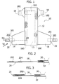
- Such an article includes a chassis 12 intended to be arranged according to a general concave configuration around the crotch region of the user.
- the chassis 12 includes an absorbent core 15 enclosed sandwich-like between a topsheet permeable to body liquids and a backsheet impermeable to such liquids.
- side panels i.e. laminar bodies - respectively rear 16 and front 18 - connectable in closed conditions around the waistline of the user on one side and the other of the article 10 at their distal margins through elements 20.
- the abovementioned side panels may also be present at only one of the ends of the chassis 12, for example avoiding the presence of side panels 18 represented in figure 1 .
- the closing elements 20 are arranged on the side panels 16 located at the rear end of the chassis 12 (intended to be set facing the back of the user). However, at least generally speaking, they could also be arranged on the side panels 18 located at the front end of the chassis 12 (intended to be set facing the stomach of the user), or equally on panels 16, or panels 18, i.e. to both ends of the chassis 12. For the sake of simplicity, the present description shall refer to embodiments in which the closing elements 20 are arranged (only) on the side panels 16 located at the rear end of the chassis 12.
- the side panels are a distinguishing characteristic of the latest articles 10.
- This system may provide for a single element 181 (referred to as frontal tape, whose profile is represented with a dot and dash line in figure 1 ) applied on the front part of the chassis 12 or two separate elements 182 (whose profiles are represented with a dashed line in figure 1 ) applied on the front part of the front panels 18.
- the elements 181 or 182 bear the loops of the hooking system, while closing elements 20 represented in figure 1 are formed by labels projecting from the distal edges of the side panels 16 and which bear a hook strip 202 intended to be coupled with the loops of the elements 181 or 182.
- FIG 1 The view of figure 1 is conceptually applied both to prior art solutions and embodiments of the solution described herein.
- FIGS. 2 and 3 correspond to an ideal sectional view according to line II-II of figure 1 and represent - with reference to solutions known and represented in simplified form - the closing element 20 respectively in unfolded position ( figure 2 ) and in folded position on the side panel 16 ( figure 3 ).
- the elements 20 project beyond the distal edge 161 of the respective side panel 16 in the condition that allows its coupling with the loop formations present (still with reference to figure 1 ) in element 181 or in elements 182.
- the elements 181 or 182 may have a larger surface extension with respect to the formations 202 in such a manner to allow a more accurate adjustment of the closed condition of the article 10 around the body of the user, preventing the article 10 from being either too tight or too loose.
- the arrangement of the hooks and the respective loops could be inverted, with the loops representing the formations 202 and the hooks representing the formations 181, 182.
- the formations 202 could simply be adhesive formations intended to be adhesively coupled with the front face of the panels 18 or of the chassis 12.
- the element 20 In the closed condition represented in figure 3 (i.e. in the condition in which the element 202 is found when the article 10 is packaged and when the article 10 is extracted from its packaging) the element 20 "embraces" the distal edge 161 of the panel 16 and the formation 202 is set facing the body of the panel 16.
- FIG. 2 also highlights the fact that the proximal margin 160 of the side panels 16 is usually anchored to the chassis 12 arranging it sandwich-like between the topsheet 30 and the backsheet 32 providing a stable connection, typically by means of gluing. Obviously, different fixing methods are possible and known to the art.
- This method of operating may lead to a given waste of material, capable of reaching up to 40-50% of the total. This fact is capable of having a negative impact especially for side panels 16 made using elastic material, implying quite high costs.
- this solution leads to using - for the panels 16 - a larger strip of material (elastic) with respect to the equivalent panel made according to the solution represented in figure 1 i.e. with the formation 202 on a label projecting from the distal margin of the panel 16.
- the width of the material on which the closing formation 202 is applied must be, so to speak, "replaced” by an equivalent portion of material of the panel 16 and this may actually jeopardise the saving of material linked to the absence of wastage.
- the object of the invention is that of meeting such need.
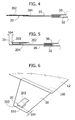
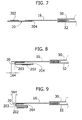
- Figures 4 and 5 as well as figures 7 and 8 represent different methods of implementation and application of the elements 20 according to embodiments considered herein.
- the view of figure 9 which again illustrates an embodiment considered herein, substantially corresponds, according to the perspective and the illustrated condition, to figures 3 , 5 and 8 .
- the arrangement or orientation of the closing formation 202 allows to unambiguously identify the "inner" side of the panel 16 even before the latter is integrated in the article 10: examining the panel 16, even alone, it shall actually be observed that its inner side or face or surface is the one on which, with the element 20 unfolded or open, the formation 202 is found.
- the formations 202 (for example with hooks) are set facing the person observing the figure, while the elements 181 or 182 (for example provided with loops) are located on the opposite side with respect to the observer.
- the arrangement of the hooks and the respective loops could be inverted, with the loops representing the formations 202 and the hooks representing the elements 181 or 182.
- the formations 182 could simply be made up of the material itself with which the side panels 18 and/or the backsheet 32 are made in case the latter is obtained by coupling an impermeable film with a non-woven fabric in such a manner that the absorbent product may confer to the user the feeling of wearing a textile product.
- the fibrous structure of the non-woven fabric replaces the loops of the specific material referred to as loop.
- An example of material suitable for such purpose is Non Woven SPUNTEN 25 gsm PHOB made by Fiberweb located in Trezzano sul Naviglio (Milan).
- the formations 202 could simply be adhesive formations intended to be adhesively coupled with the front face of the panels 18 or of the chassis 12.
- FIG. 1 Analogously to figures 2 and 3 , also the embodiments of figures 4 - 9 provide for that the element 20 be arranged and fixed - for example by gluing (in 204) - on the distal edge 161 of the side panel 16, whose proximal edge 160 is instead fixed to the chassis 12, for example inserting it sandwich-like between the topsheet 30 and the backsheet 32.
- the closing element 20 of figure 4 and 5 when arranged in closed condition ( figure 5 ), also has a general U-shaped configuration with the connection part 202 facing inwards the U-shaped formation (thus against the side panel 16).
- the U-shaped configuration in question may be a symmetric or asymmetric configuration, for example with the branch of the U-shape intended to be adhesively connected (in 204) on the side panel 16, shorter with respect to the other branch of the U-shape, the one that leads to the closing formation 202.
- This dissymmetry of the U-shaped configuration does not represent an essential characteristic for the embodiments considered herein.
- connection of the element 20 to the distal edge of the side panel 16 is attained on the "outer" side of the panel 16 (i.e. on the side intended to be set facing outwards the article 10 when worn i.e. on the side where the backsheet 32 is found) in the embodiment of figures 4 and 5
- such connection (though other connection methods, such as for example thermal bonding or ultrasonic bonding are possible, reference shall still be made to an adhesive connection for the sake of simplicity) is located on the inner side of the side panel 16 i.e. on the side intended to face towards the body of the user (inner side characterised by the presence of the topsheet 30).
- the vertex 203 of the U-shaped element be entirely arranged on the panel 16 in such a manner that present between the distal edge 161 of the panel 16 and the vertex 203 of the U-shaped configuration of the closing element 20 there be a distance 164.
- such distance 164 may vary from a minimum of 0.1 mm to a maximum of 10 mm, with a preferred distance ranging from a minimum of 3 mm to a maximum of 5 mm.
- Figure 6 illustrates a perspective representation of the embodiment represented in figures 4 and 5 fully observable from which is the fact that in the embodiment of figures 4 - 6 , the closing element 20, in its entirety, is fully found on the inner side of the elastic panel 16 and not, as it occurs in the solution represented in figures 2 and 3 , astride the distal edge of the panel 16 itself.
- connection region 204 (also in this case an adhesive, through thermal bonding, ultrasonic bonding, etc8) between the distal edge of the side panel 16 and the closing element 20 is located on the outer side of the panel 16 (i.e. on the side intended to be set facing outwards with respect to the user, i.e. on the side where the backsheet 32 is found) and, in the U-shaped closed condition ( figure 8 ), the connection formation 202 is found on the outer side of the U-shape.
- connection region 204 for example when it is attained in adhesive form, to be located on the outer surface of the panel 16, exposed towards the garments of the user. This solution is better observable, at least in some conditions of use.
- figure 9 illustrates an embodiment still referable to the general concept of arranging the closing element 20 entirely on one side of the panel 16.
- figure 9 (which in the unfolded condition of the element 20 reproduces the situation represented in figure 7 in an almost identical manner) refers to the embodiment of figures 7 and 8 regarding the arrangement of the connection zone 204 on the "outer" side of the distal edge of the panel 16.
- figure 9 provides for that, in a closed or folded condition, the longer branch of the U-shape, the one bearing the closing formation 202, be folded further in such a manner to lead the formation 202 - in the folded condition of the element 20 - to be set facing the panel 16 (and not arranged facing away from the same as represented in figure 8 ).
- the element 20 is folded according to a general S-shape wherein one can distinguish:
- This operation mode may be advantageous in various process situations, in particular using high speed application lines according to the methods similar to those described in EP-A- 1 941 853 , where - in detail - a closing element 20 as outlined in the present document may already be applied in the folded configuration, thus not requiring, passing through a special unit that folds the single closing systems 20 on the panel 16: a man skilled in the art shall observe the fact that folding the element 20 when it is still a continuous strip is technically much easier and efficient.
- the references 100 and 200 respectively indicate the sources from which the following unwind: a strip made of a first material 102 and two strips made of a second material 202 intended to obtain the body of the fixing elements 20 and the closing formations 202, respectively.
- the material unwound from the reel 100 may be a strip of non-woven fabric.
- the non-woven material PP type SMS with a basis weight of 50gr/m 2 produced by various manufacturers such as Fiberweb in Trezzano sul Naviglio (Milan), Albis in Cuneo or Atex in Settala (Milan) is exemplary of non-woven material useable in the context illustrated herein.
- the material unwound from the two reels 200 arranged paired may be, for example, a material of the hook type suitable to cooperate with a complementary material of the loop type to obtain a closure of the hook-and-loop type.
- a material useable in the present contest is the hook material manufactured by Binder GmbH in Tuttlingen (Germany).
- the method provides for the simultaneous obtainment of two symmetric strips obtained from which may be two elements 20 of the type described previously.
- the material that is unwound from the reel 100 receives starting from the two reels 200 two adjacent strips (also indicated with 202 in figure 11 for the sake of simplicity) of hook material.
- connection of the two strips or bands 202 on the strip 100 is obtained, for example, by adhesive means through glue spread on the back of the strips 202 (the term back is used to indicate the generally flat part, opposite to the one on which hooks are provided for) applied on the strip 202 in a station for applying the glue 300 interposed in the path for unwinding the strips.
- a glue suitable for use in the illustrated contest is the glue available as PM17 manufactured by Savaré Specialty Adhesives in Milan.
- the composite strip formed by the non-woven material 102 with the two strips of hook material 202 applied adjacent to each other in proximity to the centreline X100 of the strip 102 itself is then subjected - in a folding station 400 - to an operation of folding the edges (performable, for example, according to the criteria illustrated in EP-A-0 638 505 ) in such a manner to generate two strip parts folded to form a U-shape, symmetric with respect to each other, as represented in figure 12 .
- Each of these two strip parts is folded to form a U-shape according to a configuration analogous to that of the element 20 represented in figure 5 : for immediate reference, number 20 corresponds to number 102 and the adhesive connection of the formation 202 on the material 20 corresponds to the glue applied in the station 300.
- the composite strip 102/202 exiting from the folding station 400 passes through a bonding unit 500 intended to create a temporary bonding line 502 between the two branches of the U-shape sufficiently to allow each of the two U-shapes to remain closed during the subsequent treatment operations up to the packaging of the product.
- Such connection line 502 is sufficiently thin and weak to open easily when the product is opened by the user who thus proceeds to unfold the element 20 from the folded configurations represented in figure 5 , in figure 8 and in figure 9 towards the unfolded configurations represented in figure 4 and in figure 7 .
- the station 500 may be represented, for example, by a "tacking" station operating via ultrasonic thermal bonding i.e. by applying a so-called “green” glue.
- present downstream of the station 500 is a cutting station 600 intended to divide the folded composite strip 102/202 described previously in such a manner to obtain two strips each of which is suitable to be segmented in such a manner to obtain single elements 20 as represented, for example, in figure 6 .
- the abovementioned segmentation operation may be either carried out in a single production process or according to an "off-line" operation mode, such to provide for that the composite strip 102/202 before or after the longitudinal cutting operation along line X100 be wound in reels and stored. All this for subsequently using the storage reels for feeding the steps for manufacturing the actual panels 16.
- the single elements 20 bearing the closing formations 202 obtained through the longitudinal cutting and the segmentation of the composite strip 102/202 described previously are applied at predetermined distances on a strip of material 1000 adapted for manufacturing the side panels 16.
- figure 12 refers to the application of elements 20 according to a symmetric arrangement that provides for the formation of two adjacent rows of elements 20 with a predetermined pitch on the strip 1000.
- connection regions 204 represented in figures 4, 5 and 7- 9 .
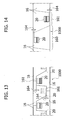
- the strip 1000 is then subjected to segmentation or according to the zig zag profile represented with a continuous line in figure 13 or simply through oblique cuttings as represented in figure 14 in such a manner to obtain single side panels.
- the closing element 20 is connected (in 204) to one of the surfaces of the side panel 16 and, in closed condition, it is folded adjacent to such surface of the side panel 16.
- the closing element 20 is folded according to a general loop condition with a branch of the loop connected (in 204) to the side panel 16 and the other branch of the loop bearing the closing formation 202.
- the closing element 20 may be applied ( figure 4-6 ) on the internal surface of the panel 16, intended to face towards the body of the user with the closing formation 202 applied inside the loop configuration.
- the closing element 20 may be applied ( figure 7 and 8 ) on the external surface of the panel 16, intended to be arranged opposite to the body of the user, i.e. facing outwards.
- the closing formation 202 may be applied on the interior of the loop configuration.
- the loop configuration includes a smaller branch connected to the side panel 16 and a larger branch bearing the closing formation 202.
- the loop configuration may be a U-shaped configuration, or a configuration in which a larger branch of the loop formation is in turn folded to form a U-shape, conferring to the closing element 20 a general S-shaped configuration with the closing formation 202 in concealed position.
Landscapes
- Health & Medical Sciences (AREA)
- Engineering & Computer Science (AREA)
- Life Sciences & Earth Sciences (AREA)
- Biomedical Technology (AREA)
- Heart & Thoracic Surgery (AREA)
- Vascular Medicine (AREA)
- Epidemiology (AREA)
- Animal Behavior & Ethology (AREA)
- General Health & Medical Sciences (AREA)
- Public Health (AREA)
- Veterinary Medicine (AREA)
- Manufacturing & Machinery (AREA)
- Absorbent Articles And Supports Therefor (AREA)
Abstract
Description
- The present disclosure refers to the sanitary products industry.
- In particular, the disclosure refers to the so-called side panels for sanitary products wearable like briefs.
- In the field of sanitary items wearable like pants (diapers for newborns and children, incontinence pads for adults, etc...), use of the structure generally represented in
figure 1 , where the article of the considered type is represented in an unfolded form, has become more and more consolidated. - Such an article, indicated in its entirety with 10, includes a
chassis 12 intended to be arranged according to a general concave configuration around the crotch region of the user. Thechassis 12 includes anabsorbent core 15 enclosed sandwich-like between a topsheet permeable to body liquids and a backsheet impermeable to such liquids. - In order to allow the
article 10 to be worn like pants, provided for fastening it around the waistline of the user are the so called side panels, i.e. laminar bodies - respectively rear 16 and front 18 - connectable in closed conditions around the waistline of the user on one side and the other of thearticle 10 at their distal margins throughelements 20. - As known to those skilled in the art, a wide range of solutions have been developed around this base over the years. These solutions regard, for example, the possibility of including in the
chassis 12 elements such as longitudinal and transverse elastic bands, cuffs intended to counter leakage of body discharges from the collection region at thecore 15, additional layers, such as so-called "acquisition layers" etc... - Analogous considerations are valid also regarding the side panels, that confer to the absorbent product the characteristic hourglass configuration.
- Initially, the abovementioned panels used to be obtained by extending the topsheet and the backsheet sideways, coupling them together using adhesives (and/or through known techniques such as thermal bonding, ultrasonic bonding) and removing from each of the two sides of the absorbent core a portion of said material coupled by means of a curved cut-out obtained between the front region, the rear region and the inner edge delimited by the longitudinal elastication strips.
- The latest developments of the product have led to reducing the width of the topsheet and of the backsheet and the hourglass shape has been replicated by applying rectangular panels or preferably shaped in proximity to the distal edges of the
chassis 12. - The abovementioned side panels may also be present at only one of the ends of the
chassis 12, for example avoiding the presence ofside panels 18 represented infigure 1 . - In the most common embodiments, the
closing elements 20 are arranged on theside panels 16 located at the rear end of the chassis 12 (intended to be set facing the back of the user). However, at least generally speaking, they could also be arranged on theside panels 18 located at the front end of the chassis 12 (intended to be set facing the stomach of the user), or equally onpanels 16, orpanels 18, i.e. to both ends of thechassis 12. For the sake of simplicity, the present description shall refer to embodiments in which theclosing elements 20 are arranged (only) on theside panels 16 located at the rear end of thechassis 12. - The side panels are a distinguishing characteristic of the
latest articles 10. - Regarding the provision of side panels, the solution concerning use of elastic material, such to confer the
article 10 good "wearability" characteristics with respect to the body of the user has become more and more consolidated over time. Particularly appreciated by the public are the embodiments that refer, within the general development of thearticle 10, to the overall hourglass shape and which have an anatomic configuration. - Regarding the
closing elements 20, alongside the traditional adhesive fixing solutions, the solutions providing for a hook-and-loop closing system have become more and more common. - This system may provide for a single element 181 (referred to as frontal tape, whose profile is represented with a dot and dash line in
figure 1 ) applied on the front part of thechassis 12 or two separate elements 182 (whose profiles are represented with a dashed line infigure 1 ) applied on the front part of thefront panels 18. Theelements closing elements 20 represented infigure 1 are formed by labels projecting from the distal edges of theside panels 16 and which bear ahook strip 202 intended to be coupled with the loops of theelements - The view of
figure 1 is conceptually applied both to prior art solutions and embodiments of the solution described herein. - The views of
figures 2 and 3 correspond to an ideal sectional view according to line II-II offigure 1 and represent - with reference to solutions known and represented in simplified form - theclosing element 20 respectively in unfolded position (figure 2 ) and in folded position on the side panel 16 (figure 3 ). - In the unfolded position, the
elements 20 project beyond thedistal edge 161 of therespective side panel 16 in the condition that allows its coupling with the loop formations present (still with reference tofigure 1 ) inelement 181 or inelements 182. Theelements formations 202 in such a manner to allow a more accurate adjustment of the closed condition of thearticle 10 around the body of the user, preventing thearticle 10 from being either too tight or too loose. - For immediate reference, it shall be observed that, with reference to the perspective of
figure 1 , the formations with thehooks 202 face the person observing the figure, while theformations - At least generally speaking, the arrangement of the hooks and the respective loops could be inverted, with the loops representing the
formations 202 and the hooks representing theformations - Furthermore, as already mentioned, the
formations 202 could simply be adhesive formations intended to be adhesively coupled with the front face of thepanels 18 or of thechassis 12. - In the closed condition represented in
figure 3 (i.e. in the condition in which theelement 202 is found when thearticle 10 is packaged and when thearticle 10 is extracted from its packaging) theelement 20 "embraces" thedistal edge 161 of thepanel 16 and theformation 202 is set facing the body of thepanel 16. - The representation of
figures 2 and 3 also highlights the fact that theproximal margin 160 of theside panels 16 is usually anchored to thechassis 12 arranging it sandwich-like between thetopsheet 30 and thebacksheet 32 providing a stable connection, typically by means of gluing. Obviously, different fixing methods are possible and known to the art. - In order to obtain a configuration like the one illustrated in
figures 2 and 3 it is possible to proceed cutting the panels 16 (for example trapezoidal-shaped, with sides more or less curved) with a shaping operation suitable to be carried out after having applied theclosing element 20 onto the material intended to form the panel. As a matter of fact, it is difficult to think of folding theclosing element 20 according to the general loop configuration represented infigure 3 on a web having discontinuity. - This method of operating may lead to a given waste of material, capable of reaching up to 40-50% of the total. This fact is capable of having a negative impact especially for
side panels 16 made using elastic material, implying quite high costs. - The manufacturers in the industry are thus keen on solutions capable of reducing if not eliminating waste of materials of this type. Regarding this, it is possible to exploit, for example, the solution described in
EP-A-1 941 853 . - Equally known is the possibility of applying the closing formation 202 (by way of example one might think of a hook formation) directly on the material of the panel 16 (and not, as represented in
figure 1 , on a label intended to project with respect to the distal edge of the panel 16). This solution has the advantage of allowing saving material, reducing to the minimum if not entirely eliminating the wastage, in a relatively simple production process (see, for example,EP-A-0 737 057 ). - However, the inventors observed that this solution has the drawback linked to the fact of applying the material intended for closing (for example the hook formation 202) directly on the elastic material of the
panel 16. This hinders, and actually does not allow, obtaining a flat configuration by the closing element. If applied on an elastic material, it always tends to acquire a curved configuration, which complicates the coupling, for example, of the hook formations with the complementary loop formations provided at the opposite end of the article. - Additionally, the inventors observed that this solution leads to using - for the panels 16 - a larger strip of material (elastic) with respect to the equivalent panel made according to the solution represented in
figure 1 i.e. with theformation 202 on a label projecting from the distal margin of thepanel 16. - Actually, if one wishes to maintain the same "useable" width of the side panel, the width of the material on which the
closing formation 202 is applied must be, so to speak, "replaced" by an equivalent portion of material of thepanel 16 and this may actually jeopardise the saving of material linked to the absence of wastage. - In the light of the information provided above, there arises the need to provide side panels for sanitary items of the type outlined above capable of:
- maintaining the advantages linked to the base solution represented in
figure 1 , in particular regarding the possibility of providing a connection formation on an element intended to project beyond the distal margin of the side panel, and - overcome the drawbacks linked, for example, to the impossibility of having connection formations capable of maintaining a flat configuration or to the fact of requiring the use of larger amounts of material for the side panels.
- The object of the invention is that of meeting such need.
- According to the present invention, such object is attained due to a side panel having the characteristics specifically referred to in the claims that follow. The invention also regards a corresponding manufacturing method as well as a sanitary article provided with a side panel of the specified type.
- The claims form an integral part of the technical disclosure provided herein in relation to the invention.
- Now, the invention shall be described, strictly for exemplifying and non-limiting purposes, with reference to the attached representations, wherein:
-
figures 1 - 3 have already been described above, -
figures 4 and 5 illustrate, for direct comparison withfigures 2 and 3 an embodiment described herein, -
figure 6 is a general perspective view of the embodiment offigures 4 and 5 , -
figures 7, 8 and 9 illustrate, for direct comparison withfigures 4 and 5 an embodiment described herein, -
figure 9 illustrates an embodiment described herein, -
figures 10 ,11 and 12 represent methods for implementing the solution described herein, withfigure 12 approximately corresponding to a section according to line XII-XII offigure 11 , and -
figures 13 and 14 illustrate embodiments of a side panel as described herein. - Illustrated in the following description are various specific details aimed at providing an in-depth understanding of the embodiments. The embodiments may be obtained without one or more specific details, or through other methods, components, materials etc. In other cases, known structures, materials or operations are not shown or described in detail to avoid obscuring the various aspects of the embodiments.
- Reference to "an embodiment" in this description indicates that a particular configuration, structure or characteristic described regarding the embodiment is included in at least one embodiment. Hence, expressions such as "in an embodiment", possibly present in various parts of this description do not necessarily refer to the same embodiment. Furthermore, particular configurations, structures or characteristics may be combined in any suitable manner in one or more embodiments.
- References herein are used for facilitating the reader and thus they do not define the scope of protection or the scope of the embodiments.
- In
figures 4 - 14 , elements, parts and components identical or equivalent to elements, parts and components described previously with reference tofigures 1 - 3 were indicated using the same reference numbers and shall not be described further herein for the sake of brevity. As already mentioned, the view offigure 1 , and - unless described otherwise hereinafter - the respective detail characteristics are applied both to prior art solutions and to the embodiment of the innovative solution subject of the present application.
-
Figures 4 and 5 as well asfigures 7 and 8 , thus correspond, the same applying to the views offigures 2 and 3 , to an ideal sectional view according to line II-II offigure 1 . -
Figures 4 and 5 as well asfigures 7 and 8 represent different methods of implementation and application of theelements 20 according to embodiments considered herein. The view offigure 9 , which again illustrates an embodiment considered herein, substantially corresponds, according to the perspective and the illustrated condition, tofigures 3 ,5 and8 . - For direct comparison with
figure 2 , it shall also be observed that the embodiments according tofigures 4 and 5 and according tofigures 7 and 8 (and 9) lead - with theelement 20 extended and projecting with respect to the body of theside panel 16, to having the closingformation 202 projecting on the "inner" side of thepanel 16 and of thearticle 10, i.e. on the side - characterised by the presence of the topsheet 30 - intended to be set facing the body of the user. - As a matter of fact, the arrangement or orientation of the
closing formation 202 allows to unambiguously identify the "inner" side of thepanel 16 even before the latter is integrated in the article 10: examining thepanel 16, even alone, it shall actually be observed that its inner side or face or surface is the one on which, with theelement 20 unfolded or open, theformation 202 is found. - In addition, for immediate reference it shall be observed that, in all the embodiments considered herein, with reference to the point of view of
figure 1 , the formations 202 (for example with hooks) are set facing the person observing the figure, while theelements 181 or 182 (for example provided with loops) are located on the opposite side with respect to the observer. At least generally, the arrangement of the hooks and the respective loops could be inverted, with the loops representing theformations 202 and the hooks representing theelements - In various embodiments, the
formations 182 could simply be made up of the material itself with which theside panels 18 and/or thebacksheet 32 are made in case the latter is obtained by coupling an impermeable film with a non-woven fabric in such a manner that the absorbent product may confer to the user the feeling of wearing a textile product. In this case, the fibrous structure of the non-woven fabric replaces the loops of the specific material referred to as loop. An example of material suitable for such purpose is Non Woven SPUNTEN 25 gsm PHOB made by Fiberweb located in Trezzano sul Naviglio (Milan). Furthermore, as already mentioned, theformations 202 could simply be adhesive formations intended to be adhesively coupled with the front face of thepanels 18 or of thechassis 12. - Analogously to
figures 2 and 3 , also the embodiments offigures 4 - 9 provide for that theelement 20 be arranged and fixed - for example by gluing (in 204) - on thedistal edge 161 of theside panel 16, whoseproximal edge 160 is instead fixed to thechassis 12, for example inserting it sandwich-like between thetopsheet 30 and thebacksheet 32. - Still analogously to the illustration outlined in
figures 2 and 3 , when arranged in closed condition (figure 5 ), also theclosing element 20 offigure 4 and 5 has a general U-shaped configuration with theconnection part 202 facing inwards the U-shaped formation (thus against the side panel 16). - The U-shaped configuration in question may be a symmetric or asymmetric configuration, for example with the branch of the U-shape intended to be adhesively connected (in 204) on the
side panel 16, shorter with respect to the other branch of the U-shape, the one that leads to theclosing formation 202. This dissymmetry of the U-shaped configuration does not represent an essential characteristic for the embodiments considered herein. - However, considering the differences between the solution illustrated in
figures 2 and 3 and the embodiment offigures 4 and 5 it shall be observed that, while in the solution offigures 2 and 3 the connection of theelement 20 to the distal edge of theside panel 16 is attained on the "outer" side of the panel 16 (i.e. on the side intended to be set facing outwards thearticle 10 when worn i.e. on the side where thebacksheet 32 is found) in the embodiment offigures 4 and 5 such connection (though other connection methods, such as for example thermal bonding or ultrasonic bonding are possible, reference shall still be made to an adhesive connection for the sake of simplicity) is located on the inner side of theside panel 16 i.e. on the side intended to face towards the body of the user (inner side characterised by the presence of the topsheet 30). - In the various embodiments described herein it is further provided for that the
vertex 203 of the U-shaped element be entirely arranged on thepanel 16 in such a manner that present between thedistal edge 161 of thepanel 16 and thevertex 203 of the U-shaped configuration of theclosing element 20 there be adistance 164. - In various embodiments,
such distance 164 may vary from a minimum of 0.1 mm to a maximum of 10 mm, with a preferred distance ranging from a minimum of 3 mm to a maximum of 5 mm. -
Figure 6 illustrates a perspective representation of the embodiment represented infigures 4 and 5 fully observable from which is the fact that in the embodiment offigures 4 - 6 , the closingelement 20, in its entirety, is fully found on the inner side of theelastic panel 16 and not, as it occurs in the solution represented infigures 2 and 3 , astride the distal edge of thepanel 16 itself. - The fact of not having to arrange the
element 20 astride the distal edge of theside panel 16 represents a simplification of the manufacturing method, in the terms that shall be more apparent hereinafter. - The same criterion, i.e. that of obtaining the
element 20 in such a manner that the same is entirely found on a side of the side panel 16 (and not astride the same, in the closed condition) is also reutilised in the embodiment offigures 7 and 8 which, once again represent the closing element 20: - in the unfolded or open condition, of use (
figure 7 , analogously tofigures 2 and4 ) and, - in the closed condition, used in the packaging step (
figure 8 , analogously tofigures 3 and5 ). - In particular, in the embodiment of
figures 7 and 8 , the connection region 204 (also in this case an adhesive, through thermal bonding, ultrasonic bonding, etc...) between the distal edge of theside panel 16 and theclosing element 20 is located on the outer side of the panel 16 (i.e. on the side intended to be set facing outwards with respect to the user, i.e. on the side where thebacksheet 32 is found) and, in the U-shaped closed condition (figure 8 ), theconnection formation 202 is found on the outer side of the U-shape. - The embodiment of
figures 7 and 8 leads to having aconnection region 204, for example when it is attained in adhesive form, to be located on the outer surface of thepanel 16, exposed towards the garments of the user. This solution is better observable, at least in some conditions of use. - Even in this case, present between the
distal edge 161 of thepanel 16 and thevertex 203 of the U-shape of theclosing element 20 is thedistance 164. - The same also applies for
figure 9 , which illustrates an embodiment still referable to the general concept of arranging theclosing element 20 entirely on one side of thepanel 16. - The embodiment of
figure 9 (which in the unfolded condition of theelement 20 reproduces the situation represented infigure 7 in an almost identical manner) refers to the embodiment offigures 7 and 8 regarding the arrangement of theconnection zone 204 on the "outer" side of the distal edge of thepanel 16. - However, the embodiment of
figure 9 provides for that, in a closed or folded condition, the longer branch of the U-shape, the one bearing theclosing formation 202, be folded further in such a manner to lead the formation 202 - in the folded condition of the element 20 - to be set facing the panel 16 (and not arranged facing away from the same as represented infigure 8 ). - In other words, in the embodiment represented in
figure 9 theelement 20 is folded according to a general S-shape wherein one can distinguish: - a proximal section, connected - in 204 - to the
panel 16, - an intermediate section, and
- a distal section that bears the
formation 202 set facing the intermediate section. - All the embodiments of
figures 5 - 9 (whose specific characteristics are freely transferable from an embodiment to another), have in common: - the fact of obtaining - in the unfolded condition (
figure 4 andfigure 7 , the latter applicable also to the solution represented infigure 9 ) - an operative configuration substantially analogous to the one represented infigure 1 , - the possibility of applying the
element 20 in closed condition (figure 5 ,figure 8 and figure 9 ) operating only on one side of thepanel 16, and - the fact of having a
distance 164 between thedistal edge 161 of thepanel 16 and thevertex 203 of the folded configuration of theelement 20. - This operation mode may be advantageous in various process situations, in particular using high speed application lines according to the methods similar to those described in
EP-A- 1 941 853 , where - in detail - aclosing element 20 as outlined in the present document may already be applied in the folded configuration, thus not requiring, passing through a special unit that folds thesingle closing systems 20 on the panel 16: a man skilled in the art shall observe the fact that folding theelement 20 when it is still a continuous strip is technically much easier and efficient. - In
figure 10 , regarding a possible method for obtaining theside panels 16 of the type described herein, thereferences first material 102 and two strips made of asecond material 202 intended to obtain the body of the fixingelements 20 and the closingformations 202, respectively. - For example, the material unwound from the
reel 100 may be a strip of non-woven fabric. The non-woven material PP type SMS with a basis weight of 50gr/m2 produced by various manufacturers such as Fiberweb in Trezzano sul Naviglio (Milan), Albis in Cuneo or Atex in Settala (Milan) is exemplary of non-woven material useable in the context illustrated herein. - The material unwound from the two
reels 200 arranged paired may be, for example, a material of the hook type suitable to cooperate with a complementary material of the loop type to obtain a closure of the hook-and-loop type. A material useable in the present contest is the hook material manufactured by Binder GmbH in Tuttlingen (Germany). - In an embodiment, as better observable in the view of
figure 12 , the method provides for the simultaneous obtainment of two symmetric strips obtained from which may be twoelements 20 of the type described previously. - For such purpose, as better observable in the view of
figure 11 , the material that is unwound from the reel 100 (indicated with 102 also infigure 11 for the sake simplicity) receives starting from the tworeels 200 two adjacent strips (also indicated with 202 infigure 11 for the sake of simplicity) of hook material. - The connection of the two strips or
bands 202 on thestrip 100 is obtained, for example, by adhesive means through glue spread on the back of the strips 202 (the term back is used to indicate the generally flat part, opposite to the one on which hooks are provided for) applied on thestrip 202 in a station for applying theglue 300 interposed in the path for unwinding the strips. A glue suitable for use in the illustrated contest is the glue available as PM17 manufactured by Savaré Specialty Adhesives in Milan. - The composite strip formed by the
non-woven material 102 with the two strips ofhook material 202 applied adjacent to each other in proximity to the centreline X100 of thestrip 102 itself is then subjected - in a folding station 400 - to an operation of folding the edges (performable, for example, according to the criteria illustrated inEP-A-0 638 505 ) in such a manner to generate two strip parts folded to form a U-shape, symmetric with respect to each other, as represented infigure 12 . Each of these two strip parts is folded to form a U-shape according to a configuration analogous to that of theelement 20 represented infigure 5 : for immediate reference,number 20 corresponds tonumber 102 and the adhesive connection of theformation 202 on thematerial 20 corresponds to the glue applied in thestation 300. - All this observing that:
- the strip exiting from the
folding station 400 includes two U-shapes (as represented infigure 5 ) connected to each other at the distal margin of the longer arm of the U-shape, and - criteria entirely analogous to that represented in
figures 10 - 12 may be applied to obtain the U-shape represented infigure 8 and, except for a more complex folding configuration, the S-shaped or Z-shaped formation represented infigure 9 . - In the illustrated embodiment, the
composite strip 102/202 exiting from thefolding station 400 passes through abonding unit 500 intended to create atemporary bonding line 502 between the two branches of the U-shape sufficiently to allow each of the two U-shapes to remain closed during the subsequent treatment operations up to the packaging of the product.Such connection line 502 is sufficiently thin and weak to open easily when the product is opened by the user who thus proceeds to unfold theelement 20 from the folded configurations represented infigure 5 , infigure 8 and infigure 9 towards the unfolded configurations represented infigure 4 and infigure 7 . - The
station 500 may be represented, for example, by a "tacking" station operating via ultrasonic thermal bonding i.e. by applying a so-called "green" glue. - In addition, present downstream of the
station 500 is a cuttingstation 600 intended to divide the foldedcomposite strip 102/202 described previously in such a manner to obtain two strips each of which is suitable to be segmented in such a manner to obtainsingle elements 20 as represented, for example, infigure 6 . - The abovementioned segmentation operation may be either carried out in a single production process or according to an "off-line" operation mode, such to provide for that the
composite strip 102/202 before or after the longitudinal cutting operation along line X100 be wound in reels and stored. All this for subsequently using the storage reels for feeding the steps for manufacturing theactual panels 16. - According to such criteria, the
single elements 20 bearing the closingformations 202 obtained through the longitudinal cutting and the segmentation of thecomposite strip 102/202 described previously are applied at predetermined distances on a strip of material 1000 adapted for manufacturing theside panels 16. - In particular
figure 12 refers to the application ofelements 20 according to a symmetric arrangement that provides for the formation of two adjacent rows ofelements 20 with a predetermined pitch on thestrip 1000. - Such application provides for the connection of the
elements 20 to thematerial 1000 with the application, for example, of adhesive regions (or through the formation of connection regions of another type: thermal bonding, ultrasonic bonding, etc..., already mentioned previously) intended to form theconnection regions 204 represented infigures 4, 5 and7- 9 . - The
strip 1000 is then subjected to segmentation or according to the zig zag profile represented with a continuous line infigure 13 or simply through oblique cuttings as represented infigure 14 in such a manner to obtain single side panels. - The latter are then applied on an article such as the
article 10 offigure 1 according to the methods described more in detail inEP-A-1 941 853 already mentioned several times previously. - In any case, such techniques obtain advantage from the fact that, in the embodiments exemplified herein, the closing
element 20 is connected (in 204) to one of the surfaces of theside panel 16 and, in closed condition, it is folded adjacent to such surface of theside panel 16. - In various embodiments (for example
figure 5 and8 ) in the abovementioned closed condition, the closingelement 20 is folded according to a general loop condition with a branch of the loop connected (in 204) to theside panel 16 and the other branch of the loop bearing theclosing formation 202. - The closing
element 20 may be applied (figure 4-6 ) on the internal surface of thepanel 16, intended to face towards the body of the user with theclosing formation 202 applied inside the loop configuration. - The closing
element 20 may be applied (figure 7 and 8 ) on the external surface of thepanel 16, intended to be arranged opposite to the body of the user, i.e. facing outwards. Theclosing formation 202 may be applied on the interior of the loop configuration. - In various embodiments the loop configuration includes a smaller branch connected to the
side panel 16 and a larger branch bearing theclosing formation 202. - The loop configuration may be a U-shaped configuration, or a configuration in which a larger branch of the loop formation is in turn folded to form a U-shape, conferring to the closing element 20 a general S-shaped configuration with the
closing formation 202 in concealed position. - Hence, without prejudice to the underlying principle of the invention, the details and embodiments may vary, even significantly, with respect to what has been described herein by way of non-limiting example only, without departing from the scope of the invention as defined by the attached claims.
Claims (16)
- A side panel (16) for sanitary articles (10) wearable like pants, said side panel (16) including a laminar body with two opposite surfaces having a proximal edge (160) for connection to the chassis (12) of said article (10) and a distal edge (161) bearing an element (20) for closing the article (10), said closing element (20) having a closing formation (202) unfoldable towards an unfolded use position, wherein said closing element (20) projects from said distal edge of the side panel (16), starting from a closed condition wherein said closing element (20) is folded adjacent to the side panel (16), characterised in that the closing element (20) is connected (204) to one of said surfaces of the side panel (16) and, in said closed condition, it is folded against said one of said surfaces of the side panel (16).
- The panel according to claim 1, wherein, in said closed condition, said closing element (20) is located at a distance (164) from the distal edge (161) of the panel (16).
- The panel according to claim 2, wherein said distance (164) is between 0.1 mm and 10 mm, preferably between 3 mm and 5mm.
- The panel according to any one of the preceding claims, wherein, in said closed condition, said closing element (20) is folded according to a loop configuration with a branch of said loop connected (204) to said one of said surfaces of the side panel (16) and the other branch of the loop bearing said closing formation (202).
- The panel according to claim 4, wherein said closing element (20) is applied on the inner surface of said panel (16) intended to face towards the body of the user, with said closing formation (202) applied inside said loop configuration.
- The panel according to claim 4, wherein said closing element (20) is applied on the outer surface of said side panel (16) intended to be opposite with respect to the body of the user, with said closing formation (202) applied outside said loop configuration.
- The panel according to any one of claims 4 - 6, wherein said loop configuration includes a shorter branch (204) connected to said one of said surfaces of the side panel (16) and a longer branch bearing said closing formation (202).
- The panel according to any one of claims 4 - 7, wherein said loop configuration is a U-shaped configuration.
- The panel according to claim 7, wherein said longer branch of said loop formation is in turn folded to form a U-shape, conferring to said closing element (20) in said closed condition a general S-shaped configuration with said closing formation (202) in a concealed position.
- The panel according to any one of the preceding claims, wherein said closing element (20) is connected (204) to said side panel (16) by adhesive means, through thermal bonding or through ultrasonic bonding.
- The panel according to any one of the preceding claims, wherein said closing formation (202) is an adhesive formation.
- The panel according to any one of claims 1 - 10, wherein said closing formation (202) is one of the parts of a hook-and-loop closure.
- The panel according to claim 12, wherein said closing formation (202) is the hook part of a hook-and-loop closure.
- A method of producing a side panel according to any one of claims 1 - 13, including applying said closing element (20) to one of said surfaces of the side panel (16) in said closed condition, whereby said closing element (20) is applied folded onto said one of said surfaces of the side panel (16).
- The method according to claim 14, including:- providing a first strip (102) of laminate material for obtaining said closing elements, said first strip having a centreline (X100),- providing two combined second strips (202) of material for obtaining said closing formation,- connecting said two second strips (202) on said first strip (102) in combined positions on opposite sides of the centreline (X100), and- folding the external edges of said first strip (102) towards said centreline (X100) in such a manner to produce a composite strip including two branches symmetric with respect to said centreline (X100), each branch having a transverse loop profile and being segmentable to obtain said closing elements (20), each applicable on a side panel (16) in said closed condition.
- A sanitary article (10) wearable like pants including:- a main body (12) to be arranged concave around the body of the user and having a front end and a rear end, and- a pair of side panels (16) according to any one of claims 1 - 13 applied symmetrically on opposite sides of said chassis (12) in correspondence with at least one of the front and rear ends of the article (10).
Priority Applications (4)
| Application Number | Priority Date | Filing Date | Title |
|---|---|---|---|
| DK09425207.9T DK2255764T3 (en) | 2009-05-26 | 2009-05-26 | Side panel for hygiene products, similar manufacturing method and product |
| EP09425207.9A EP2255764B1 (en) | 2009-05-26 | 2009-05-26 | A side panel for sanitary articles, corresponding method of manufacture and article |
| ES09425207T ES2435426T3 (en) | 2009-05-26 | 2009-05-26 | Side panel for sanitary ware, corresponding manufacturing method and article |
| PCT/IB2010/052203 WO2010136933A1 (en) | 2009-05-26 | 2010-05-18 | A side panel for sanitary articles, corresponding method of manufacture and article |
Applications Claiming Priority (1)
| Application Number | Priority Date | Filing Date | Title |
|---|---|---|---|
| EP09425207.9A EP2255764B1 (en) | 2009-05-26 | 2009-05-26 | A side panel for sanitary articles, corresponding method of manufacture and article |
Publications (2)
| Publication Number | Publication Date |
|---|---|
| EP2255764A1 true EP2255764A1 (en) | 2010-12-01 |
| EP2255764B1 EP2255764B1 (en) | 2013-09-11 |
Family
ID=41009779
Family Applications (1)
| Application Number | Title | Priority Date | Filing Date |
|---|---|---|---|
| EP09425207.9A Not-in-force EP2255764B1 (en) | 2009-05-26 | 2009-05-26 | A side panel for sanitary articles, corresponding method of manufacture and article |
Country Status (4)
| Country | Link |
|---|---|
| EP (1) | EP2255764B1 (en) |
| DK (1) | DK2255764T3 (en) |
| ES (1) | ES2435426T3 (en) |
| WO (1) | WO2010136933A1 (en) |
Cited By (1)
| Publication number | Priority date | Publication date | Assignee | Title |
|---|---|---|---|---|
| ITBO20130335A1 (en) * | 2013-06-28 | 2014-12-29 | Gdm Spa | METHOD AND EQUIPMENT FOR THE PRODUCTION OF HYGIENIC ABSORBENTS. |
Families Citing this family (4)
| Publication number | Priority date | Publication date | Assignee | Title |
|---|---|---|---|---|
| IT1398206B1 (en) | 2010-02-16 | 2013-02-14 | Fameccanica Data Spa | PROCEDURE FOR PRODUCING HYGIENE-HEALTH ARTICLES WEARABLE WITH THE GUIDE OF MUTANDINA AND CORRESPONDENT ARTICLE. |
| US10470941B2 (en) * | 2014-10-27 | 2019-11-12 | Gdm S.P.A. | Method for making absorbent sanitary articles |
| KR102764725B1 (en) * | 2019-12-20 | 2025-02-11 | 킴벌리-클라크 월드와이드, 인크. | Method for forming a plurality of absorbent articles having refastenable side seams |
| MX2022006552A (en) * | 2019-12-20 | 2022-08-04 | Kimberly Clark Co | Absorbent article with refastenable side seams and method of manufacturing. |
Citations (9)
| Publication number | Priority date | Publication date | Assignee | Title |
|---|---|---|---|---|
| US4317449A (en) * | 1980-01-28 | 1982-03-02 | Warner-Lambert Company | Disposable adult incontinent brief |
| EP0638505A1 (en) | 1993-08-09 | 1995-02-15 | Mima Incorporated | An apparatus and method for hemming edges of stretch film and a film having hemmed edges |
| US5531731A (en) * | 1994-09-07 | 1996-07-02 | Kimberly-Clark Corporation | Tape fastener for conveying information and method of manufacture |
| EP0737057A1 (en) | 1993-12-28 | 1996-10-16 | Kimberly-Clark Worldwide, Inc. | Elastomeric ears for disposable absorbent article |
| DE9422298U1 (en) * | 1994-02-23 | 1999-10-28 | Kimberly-Clark Worldwide, Inc., Neenah, Wis. | Strip and fastening arrangements |
| US20050048303A1 (en) * | 2003-08-29 | 2005-03-03 | Henderson Kevin O. | Multilayer films, adhesive constructions, and articles using the same |
| US20060271004A1 (en) * | 2003-02-28 | 2006-11-30 | Petersen Johann F | Method of preparing closure components suitable for use in diapers |
| WO2007071267A1 (en) * | 2005-12-19 | 2007-06-28 | Sca Hygiene Products Ab | Multi-configurable absorbent article |
| EP1941853A1 (en) | 2007-01-02 | 2008-07-09 | Fameccanica.Data S.p.A. | A side panel for sanitary articles, corresponding sanitary article and method of producing same |
-
2009
- 2009-05-26 DK DK09425207.9T patent/DK2255764T3/en active
- 2009-05-26 EP EP09425207.9A patent/EP2255764B1/en not_active Not-in-force
- 2009-05-26 ES ES09425207T patent/ES2435426T3/en active Active
-
2010
- 2010-05-18 WO PCT/IB2010/052203 patent/WO2010136933A1/en not_active Ceased
Patent Citations (9)
| Publication number | Priority date | Publication date | Assignee | Title |
|---|---|---|---|---|
| US4317449A (en) * | 1980-01-28 | 1982-03-02 | Warner-Lambert Company | Disposable adult incontinent brief |
| EP0638505A1 (en) | 1993-08-09 | 1995-02-15 | Mima Incorporated | An apparatus and method for hemming edges of stretch film and a film having hemmed edges |
| EP0737057A1 (en) | 1993-12-28 | 1996-10-16 | Kimberly-Clark Worldwide, Inc. | Elastomeric ears for disposable absorbent article |
| DE9422298U1 (en) * | 1994-02-23 | 1999-10-28 | Kimberly-Clark Worldwide, Inc., Neenah, Wis. | Strip and fastening arrangements |
| US5531731A (en) * | 1994-09-07 | 1996-07-02 | Kimberly-Clark Corporation | Tape fastener for conveying information and method of manufacture |
| US20060271004A1 (en) * | 2003-02-28 | 2006-11-30 | Petersen Johann F | Method of preparing closure components suitable for use in diapers |
| US20050048303A1 (en) * | 2003-08-29 | 2005-03-03 | Henderson Kevin O. | Multilayer films, adhesive constructions, and articles using the same |
| WO2007071267A1 (en) * | 2005-12-19 | 2007-06-28 | Sca Hygiene Products Ab | Multi-configurable absorbent article |
| EP1941853A1 (en) | 2007-01-02 | 2008-07-09 | Fameccanica.Data S.p.A. | A side panel for sanitary articles, corresponding sanitary article and method of producing same |
Cited By (2)
| Publication number | Priority date | Publication date | Assignee | Title |
|---|---|---|---|---|
| ITBO20130335A1 (en) * | 2013-06-28 | 2014-12-29 | Gdm Spa | METHOD AND EQUIPMENT FOR THE PRODUCTION OF HYGIENIC ABSORBENTS. |
| WO2014207698A1 (en) * | 2013-06-28 | 2014-12-31 | Gdm S.P.A. | Method and apparatus for manufacturing absorbent sanitary articles |
Also Published As
| Publication number | Publication date |
|---|---|
| ES2435426T3 (en) | 2013-12-19 |
| DK2255764T3 (en) | 2013-10-28 |
| WO2010136933A1 (en) | 2010-12-02 |
| EP2255764B1 (en) | 2013-09-11 |
Similar Documents
| Publication | Publication Date | Title |
|---|---|---|
| CN1893899B (en) | Method of forming a waistband on an absorbent article | |
| RU2580990C2 (en) | Disposable diaper and method of its manufacturing | |
| CN102686190B (en) | Pants-type diaper and production method thereof | |
| US6540730B1 (en) | Front opening briefs with integral support panel | |
| CA2717299C (en) | Absorbent article having an umbilical notch cut | |
| CN105853070A (en) | Small-sized disposable pull-on diaper | |
| US20110247199A1 (en) | Reconfigurable Converting Lines and Methods for Fabricating Both Taped Diapers and Pant Diapers | |
| EP2255764B1 (en) | A side panel for sanitary articles, corresponding method of manufacture and article | |
| JP2017504380A (en) | Diapers with improved shape and fit | |
| JP2017504381A (en) | Diapers with improved shape and fit | |
| KR20010101273A (en) | Absorbent Article with Non-irritating Refastenable Seams | |
| US12156796B2 (en) | Hygiene article comprising a skin protection sheet with well positioned opening(s) | |
| JP2016529977A (en) | Diapers with cuff connectors | |
| JP2017503549A (en) | Diapers with improved shape and fit | |
| SG174375A1 (en) | Disposable diaper having a fastening tape with stepwise adjustable length | |
| JP4812295B2 (en) | Absorbent hygiene product closure element, method of manufacture, method of use thereof, and absorbent hygiene product | |
| JP2016539742A (en) | Diapers with improved shape and fit | |
| US20120246915A1 (en) | Converting System for Fabricating Taped Diapers and Pant Diapers | |
| JP6137911B2 (en) | Disposable wearing items | |
| CN107920928A (en) | There is band structure with figure | |
| JP4309594B2 (en) | Disposable diapers | |
| CN103025290A (en) | Sorbent article having fastening members with indicium | |
| US8348917B2 (en) | Stretched, necked, unitary garment and a method of manufacturing same | |
| MX2013010975A (en) | Converting system for fabricating taped diapers and pant diapers. | |
| WO2020062132A1 (en) | Wearable article having disposal wrapping means |
Legal Events
| Date | Code | Title | Description |
|---|---|---|---|
| PUAI | Public reference made under article 153(3) epc to a published international application that has entered the european phase |
Free format text: ORIGINAL CODE: 0009012 |
|
| AK | Designated contracting states |
Kind code of ref document: A1 Designated state(s): AT BE BG CH CY CZ DE DK EE ES FI FR GB GR HR HU IE IS IT LI LT LU LV MC MK MT NL NO PL PT RO SE SI SK TR |
|
| AX | Request for extension of the european patent |
Extension state: AL BA RS |
|
| 17P | Request for examination filed |
Effective date: 20110330 |
|
| 17Q | First examination report despatched |
Effective date: 20110414 |
|
| REG | Reference to a national code |
Ref country code: DE Ref legal event code: R079 Ref document number: 602009018697 Country of ref document: DE Free format text: PREVIOUS MAIN CLASS: A61F0013150000 Ipc: A61F0013490000 |
|
| GRAP | Despatch of communication of intention to grant a patent |
Free format text: ORIGINAL CODE: EPIDOSNIGR1 |
|
| RIC1 | Information provided on ipc code assigned before grant |
Ipc: A61F 13/15 20060101ALI20130411BHEP Ipc: A61F 13/56 20060101ALI20130411BHEP Ipc: A61F 13/49 20060101AFI20130411BHEP |
|
| INTG | Intention to grant announced |
Effective date: 20130429 |
|
| GRAS | Grant fee paid |
Free format text: ORIGINAL CODE: EPIDOSNIGR3 |
|
| GRAA | (expected) grant |
Free format text: ORIGINAL CODE: 0009210 |
|
| AK | Designated contracting states |
Kind code of ref document: B1 Designated state(s): AT BE BG CH CY CZ DE DK EE ES FI FR GB GR HR HU IE IS IT LI LT LU LV MC MK MT NL NO PL PT RO SE SI SK TR |
|
| REG | Reference to a national code |
Ref country code: GB Ref legal event code: FG4D |
|
| REG | Reference to a national code |
Ref country code: CH Ref legal event code: EP Ref country code: CH Ref legal event code: NV Representative=s name: ISLER AND PEDRAZZINI AG, CH |
|
| REG | Reference to a national code |
Ref country code: AT Ref legal event code: REF Ref document number: 631201 Country of ref document: AT Kind code of ref document: T Effective date: 20130915 |
|
| REG | Reference to a national code |
Ref country code: IE Ref legal event code: FG4D |
|
| REG | Reference to a national code |
Ref country code: DK Ref legal event code: T3 Effective date: 20131022 Ref country code: DK |
|
| REG | Reference to a national code |
Ref country code: SE Ref legal event code: TRGR |
|
| REG | Reference to a national code |
Ref country code: DE Ref legal event code: R096 Ref document number: 602009018697 Country of ref document: DE Effective date: 20131107 |
|
| RAP2 | Party data changed (patent owner data changed or rights of a patent transferred) |
Owner name: FAMECCANICA.DATA S.P.A. |
|
| REG | Reference to a national code |
Ref country code: ES Ref legal event code: FG2A Ref document number: 2435426 Country of ref document: ES Kind code of ref document: T3 Effective date: 20131219 |
|
| PG25 | Lapsed in a contracting state [announced via postgrant information from national office to epo] |
Ref country code: HR Free format text: LAPSE BECAUSE OF FAILURE TO SUBMIT A TRANSLATION OF THE DESCRIPTION OR TO PAY THE FEE WITHIN THE PRESCRIBED TIME-LIMIT Effective date: 20130911 Ref country code: NO Free format text: LAPSE BECAUSE OF FAILURE TO SUBMIT A TRANSLATION OF THE DESCRIPTION OR TO PAY THE FEE WITHIN THE PRESCRIBED TIME-LIMIT Effective date: 20131211 Ref country code: CY Free format text: LAPSE BECAUSE OF FAILURE TO SUBMIT A TRANSLATION OF THE DESCRIPTION OR TO PAY THE FEE WITHIN THE PRESCRIBED TIME-LIMIT Effective date: 20130911 Ref country code: LT Free format text: LAPSE BECAUSE OF FAILURE TO SUBMIT A TRANSLATION OF THE DESCRIPTION OR TO PAY THE FEE WITHIN THE PRESCRIBED TIME-LIMIT Effective date: 20130911 |
|
| REG | Reference to a national code |
Ref country code: NL Ref legal event code: VDEP Effective date: 20130911 |
|
| REG | Reference to a national code |
Ref country code: AT Ref legal event code: MK05 Ref document number: 631201 Country of ref document: AT Kind code of ref document: T Effective date: 20130911 |
|
| REG | Reference to a national code |
Ref country code: LT Ref legal event code: MG4D |
|
| PG25 | Lapsed in a contracting state [announced via postgrant information from national office to epo] |
Ref country code: GR Free format text: LAPSE BECAUSE OF FAILURE TO SUBMIT A TRANSLATION OF THE DESCRIPTION OR TO PAY THE FEE WITHIN THE PRESCRIBED TIME-LIMIT Effective date: 20131212 Ref country code: LV Free format text: LAPSE BECAUSE OF FAILURE TO SUBMIT A TRANSLATION OF THE DESCRIPTION OR TO PAY THE FEE WITHIN THE PRESCRIBED TIME-LIMIT Effective date: 20130911 Ref country code: SI Free format text: LAPSE BECAUSE OF FAILURE TO SUBMIT A TRANSLATION OF THE DESCRIPTION OR TO PAY THE FEE WITHIN THE PRESCRIBED TIME-LIMIT Effective date: 20130911 Ref country code: FI Free format text: LAPSE BECAUSE OF FAILURE TO SUBMIT A TRANSLATION OF THE DESCRIPTION OR TO PAY THE FEE WITHIN THE PRESCRIBED TIME-LIMIT Effective date: 20130911 |
|
| PG25 | Lapsed in a contracting state [announced via postgrant information from national office to epo] |
Ref country code: SK Free format text: LAPSE BECAUSE OF FAILURE TO SUBMIT A TRANSLATION OF THE DESCRIPTION OR TO PAY THE FEE WITHIN THE PRESCRIBED TIME-LIMIT Effective date: 20130911 Ref country code: NL Free format text: LAPSE BECAUSE OF FAILURE TO SUBMIT A TRANSLATION OF THE DESCRIPTION OR TO PAY THE FEE WITHIN THE PRESCRIBED TIME-LIMIT Effective date: 20130911 Ref country code: EE Free format text: LAPSE BECAUSE OF FAILURE TO SUBMIT A TRANSLATION OF THE DESCRIPTION OR TO PAY THE FEE WITHIN THE PRESCRIBED TIME-LIMIT Effective date: 20130911 Ref country code: RO Free format text: LAPSE BECAUSE OF FAILURE TO SUBMIT A TRANSLATION OF THE DESCRIPTION OR TO PAY THE FEE WITHIN THE PRESCRIBED TIME-LIMIT Effective date: 20130911 Ref country code: IS Free format text: LAPSE BECAUSE OF FAILURE TO SUBMIT A TRANSLATION OF THE DESCRIPTION OR TO PAY THE FEE WITHIN THE PRESCRIBED TIME-LIMIT Effective date: 20140111 Ref country code: CZ Free format text: LAPSE BECAUSE OF FAILURE TO SUBMIT A TRANSLATION OF THE DESCRIPTION OR TO PAY THE FEE WITHIN THE PRESCRIBED TIME-LIMIT Effective date: 20130911 |
|
| PG25 | Lapsed in a contracting state [announced via postgrant information from national office to epo] |
Ref country code: AT Free format text: LAPSE BECAUSE OF FAILURE TO SUBMIT A TRANSLATION OF THE DESCRIPTION OR TO PAY THE FEE WITHIN THE PRESCRIBED TIME-LIMIT Effective date: 20130911 Ref country code: PL Free format text: LAPSE BECAUSE OF FAILURE TO SUBMIT A TRANSLATION OF THE DESCRIPTION OR TO PAY THE FEE WITHIN THE PRESCRIBED TIME-LIMIT Effective date: 20130911 |
|
| REG | Reference to a national code |
Ref country code: DE Ref legal event code: R097 Ref document number: 602009018697 Country of ref document: DE |
|
| PG25 | Lapsed in a contracting state [announced via postgrant information from national office to epo] |
Ref country code: PT Free format text: LAPSE BECAUSE OF FAILURE TO SUBMIT A TRANSLATION OF THE DESCRIPTION OR TO PAY THE FEE WITHIN THE PRESCRIBED TIME-LIMIT Effective date: 20140113 |
|
| PLBE | No opposition filed within time limit |
Free format text: ORIGINAL CODE: 0009261 |
|
| STAA | Information on the status of an ep patent application or granted ep patent |
Free format text: STATUS: NO OPPOSITION FILED WITHIN TIME LIMIT |
|
| REG | Reference to a national code |
Ref country code: GB Ref legal event code: S117 Free format text: REQUEST FILED; REQUEST FOR CORRECTION UNDER SECTION 117 FILED ON 23 JUNE 2014 |
|
| 26N | No opposition filed |
Effective date: 20140612 |
|
| REG | Reference to a national code |
Ref country code: GB Ref legal event code: S117 Free format text: CORRECTIONS ALLOWED; REQUEST FOR CORRECTION UNDER SECTION 117 FILED ON 23 JUNE 2014, ALLOWED ON 08 AUGUST 2014 |
|
| REG | Reference to a national code |
Ref country code: DE Ref legal event code: R097 Ref document number: 602009018697 Country of ref document: DE Effective date: 20140612 |
|
| PG25 | Lapsed in a contracting state [announced via postgrant information from national office to epo] |
Ref country code: LU Free format text: LAPSE BECAUSE OF FAILURE TO SUBMIT A TRANSLATION OF THE DESCRIPTION OR TO PAY THE FEE WITHIN THE PRESCRIBED TIME-LIMIT Effective date: 20140526 |
|
| PG25 | Lapsed in a contracting state [announced via postgrant information from national office to epo] |
Ref country code: MC Free format text: LAPSE BECAUSE OF FAILURE TO SUBMIT A TRANSLATION OF THE DESCRIPTION OR TO PAY THE FEE WITHIN THE PRESCRIBED TIME-LIMIT Effective date: 20130911 |
|
| REG | Reference to a national code |
Ref country code: IE Ref legal event code: MM4A |
|
| PG25 | Lapsed in a contracting state [announced via postgrant information from national office to epo] |
Ref country code: IE Free format text: LAPSE BECAUSE OF NON-PAYMENT OF DUE FEES Effective date: 20140526 |
|
| PG25 | Lapsed in a contracting state [announced via postgrant information from national office to epo] |
Ref country code: MT Free format text: LAPSE BECAUSE OF FAILURE TO SUBMIT A TRANSLATION OF THE DESCRIPTION OR TO PAY THE FEE WITHIN THE PRESCRIBED TIME-LIMIT Effective date: 20130911 |
|
| REG | Reference to a national code |
Ref country code: FR Ref legal event code: PLFP Year of fee payment: 8 |
|
| PG25 | Lapsed in a contracting state [announced via postgrant information from national office to epo] |
Ref country code: BG Free format text: LAPSE BECAUSE OF FAILURE TO SUBMIT A TRANSLATION OF THE DESCRIPTION OR TO PAY THE FEE WITHIN THE PRESCRIBED TIME-LIMIT Effective date: 20130911 |
|
| PG25 | Lapsed in a contracting state [announced via postgrant information from national office to epo] |
Ref country code: TR Free format text: LAPSE BECAUSE OF FAILURE TO SUBMIT A TRANSLATION OF THE DESCRIPTION OR TO PAY THE FEE WITHIN THE PRESCRIBED TIME-LIMIT Effective date: 20130911 Ref country code: HU Free format text: LAPSE BECAUSE OF FAILURE TO SUBMIT A TRANSLATION OF THE DESCRIPTION OR TO PAY THE FEE WITHIN THE PRESCRIBED TIME-LIMIT; INVALID AB INITIO Effective date: 20090526 |
|
| REG | Reference to a national code |
Ref country code: FR Ref legal event code: PLFP Year of fee payment: 9 |
|
| REG | Reference to a national code |
Ref country code: FR Ref legal event code: PLFP Year of fee payment: 10 |
|
| PG25 | Lapsed in a contracting state [announced via postgrant information from national office to epo] |
Ref country code: MK Free format text: LAPSE BECAUSE OF FAILURE TO SUBMIT A TRANSLATION OF THE DESCRIPTION OR TO PAY THE FEE WITHIN THE PRESCRIBED TIME-LIMIT Effective date: 20130911 |
|
| PGFP | Annual fee paid to national office [announced via postgrant information from national office to epo] |
Ref country code: DK Payment date: 20180525 Year of fee payment: 10 |
|
| PGFP | Annual fee paid to national office [announced via postgrant information from national office to epo] |
Ref country code: DE Payment date: 20190530 Year of fee payment: 11 Ref country code: ES Payment date: 20190603 Year of fee payment: 11 Ref country code: IT Payment date: 20190523 Year of fee payment: 11 |
|
| PGFP | Annual fee paid to national office [announced via postgrant information from national office to epo] |
Ref country code: BE Payment date: 20190527 Year of fee payment: 11 Ref country code: SE Payment date: 20190531 Year of fee payment: 11 Ref country code: FR Payment date: 20190527 Year of fee payment: 11 |
|
| PGFP | Annual fee paid to national office [announced via postgrant information from national office to epo] |
Ref country code: CH Payment date: 20190604 Year of fee payment: 11 |
|
| PGFP | Annual fee paid to national office [announced via postgrant information from national office to epo] |
Ref country code: GB Payment date: 20190528 Year of fee payment: 11 |
|
| REG | Reference to a national code |
Ref country code: DK Ref legal event code: EBP Effective date: 20190531 |
|
| PG25 | Lapsed in a contracting state [announced via postgrant information from national office to epo] |
Ref country code: DK Free format text: LAPSE BECAUSE OF NON-PAYMENT OF DUE FEES Effective date: 20190531 |
|
| REG | Reference to a national code |
Ref country code: DE Ref legal event code: R119 Ref document number: 602009018697 Country of ref document: DE |
|
| PG25 | Lapsed in a contracting state [announced via postgrant information from national office to epo] |
Ref country code: CH Free format text: LAPSE BECAUSE OF NON-PAYMENT OF DUE FEES Effective date: 20200531 Ref country code: LI Free format text: LAPSE BECAUSE OF NON-PAYMENT OF DUE FEES Effective date: 20200531 Ref country code: SE Free format text: LAPSE BECAUSE OF NON-PAYMENT OF DUE FEES Effective date: 20200527 |
|
| REG | Reference to a national code |
Ref country code: BE Ref legal event code: MM Effective date: 20200531 |
|
| GBPC | Gb: european patent ceased through non-payment of renewal fee |
Effective date: 20200526 |
|
| PG25 | Lapsed in a contracting state [announced via postgrant information from national office to epo] |
Ref country code: FR Free format text: LAPSE BECAUSE OF NON-PAYMENT OF DUE FEES Effective date: 20200531 Ref country code: GB Free format text: LAPSE BECAUSE OF NON-PAYMENT OF DUE FEES Effective date: 20200526 |
|
| PG25 | Lapsed in a contracting state [announced via postgrant information from national office to epo] |
Ref country code: DE Free format text: LAPSE BECAUSE OF NON-PAYMENT OF DUE FEES Effective date: 20201201 Ref country code: BE Free format text: LAPSE BECAUSE OF NON-PAYMENT OF DUE FEES Effective date: 20200531 |
|
| PG25 | Lapsed in a contracting state [announced via postgrant information from national office to epo] |
Ref country code: IT Free format text: LAPSE BECAUSE OF NON-PAYMENT OF DUE FEES Effective date: 20200526 |
|
| PG25 | Lapsed in a contracting state [announced via postgrant information from national office to epo] |
Ref country code: ES Free format text: LAPSE BECAUSE OF NON-PAYMENT OF DUE FEES Effective date: 20200527 |