EP2255733A1 - Suture passing instrument - Google Patents
Suture passing instrument Download PDFInfo
- Publication number
- EP2255733A1 EP2255733A1 EP10164237A EP10164237A EP2255733A1 EP 2255733 A1 EP2255733 A1 EP 2255733A1 EP 10164237 A EP10164237 A EP 10164237A EP 10164237 A EP10164237 A EP 10164237A EP 2255733 A1 EP2255733 A1 EP 2255733A1
- Authority
- EP
- European Patent Office
- Prior art keywords
- jaw
- suture
- needle
- passing instrument
- suture passing
- Prior art date
- Legal status (The legal status is an assumption and is not a legal conclusion. Google has not performed a legal analysis and makes no representation as to the accuracy of the status listed.)
- Granted
Links
Images


Classifications
-
- A—HUMAN NECESSITIES
- A61—MEDICAL OR VETERINARY SCIENCE; HYGIENE
- A61B—DIAGNOSIS; SURGERY; IDENTIFICATION
- A61B17/00—Surgical instruments, devices or methods
- A61B17/04—Surgical instruments, devices or methods for suturing wounds; Holders or packages for needles or suture materials
- A61B17/06—Needles ; Sutures; Needle-suture combinations; Holders or packages for needles or suture materials
- A61B17/062—Needle manipulators
- A61B17/0625—Needle manipulators the needle being specially adapted to interact with the manipulator, e.g. being ridged to snap fit in a hole of the manipulator
-
- A—HUMAN NECESSITIES
- A61—MEDICAL OR VETERINARY SCIENCE; HYGIENE
- A61B—DIAGNOSIS; SURGERY; IDENTIFICATION
- A61B17/00—Surgical instruments, devices or methods
- A61B17/04—Surgical instruments, devices or methods for suturing wounds; Holders or packages for needles or suture materials
- A61B17/0469—Suturing instruments for use in minimally invasive surgery, e.g. endoscopic surgery
-
- A—HUMAN NECESSITIES
- A61—MEDICAL OR VETERINARY SCIENCE; HYGIENE
- A61B—DIAGNOSIS; SURGERY; IDENTIFICATION
- A61B17/00—Surgical instruments, devices or methods
- A61B17/04—Surgical instruments, devices or methods for suturing wounds; Holders or packages for needles or suture materials
- A61B17/0482—Needle or suture guides
-
- A—HUMAN NECESSITIES
- A61—MEDICAL OR VETERINARY SCIENCE; HYGIENE
- A61B—DIAGNOSIS; SURGERY; IDENTIFICATION
- A61B17/00—Surgical instruments, devices or methods
- A61B17/28—Surgical forceps
- A61B17/29—Forceps for use in minimally invasive surgery
-
- A—HUMAN NECESSITIES
- A61—MEDICAL OR VETERINARY SCIENCE; HYGIENE
- A61B—DIAGNOSIS; SURGERY; IDENTIFICATION
- A61B17/00—Surgical instruments, devices or methods
- A61B17/04—Surgical instruments, devices or methods for suturing wounds; Holders or packages for needles or suture materials
- A61B17/06—Needles ; Sutures; Needle-suture combinations; Holders or packages for needles or suture materials
- A61B17/06004—Means for attaching suture to needle
- A61B2017/06042—Means for attaching suture to needle located close to needle tip
Definitions
- the invention relates to suture passing surgical instruments. More specifically, the invention relates to a hand instrument and method for passing suture through tissue.
- a suture passing device having a low profile that can accommodate many thicknesses of tissue, is easy to load with a suture and utilizes a mechanism that is easy and reliable for threading the suture through tissue.
- a suture passing instrument that is of simple configuration so that a suture may be loaded into the instrument with relative ease. It is a further object of the present invention to provide a suture passing instrument having wide opening jaws so that it may be used with a range of tissue thickness. It is a further object of the invention to provide a suture passing instrument which prevents tangling of the suture and only threads one loop of suture through the tissue as desired. A further object of the invention is to provide a suture passing instrument which may be operated with one hand.
- a suture passing instrument comprising a first jaw coupled to an end of an elongated shaft, a second jaw coupled to the first jaw, and formed with a holder for supporting a suture, and a needle slidably disposed within the first jaw, the needle having a hook on a side for releasably capturing a portion of a suture.
- the first jaw defines a channel for receiving the needle and a ramp for deflecting the needle transversely of the shaft when advanced to an extended position.
- the first jaw is stationary and the second jaw is movable and may be pivotally coupled to the first jaw.
- the needle may be made from a malleable material and may have a sharp distal tip for piercing tissue.
- An opening may also be formed in the second jaw that provides a clearance for a tip portion of the needle to pass when it is advanced to its extended position.
- the opening and the holder may be aligned such that a suture received in the holder extends across the opening.
- the holder supports the suture on an inner surface of the movable jaw facing the stationary jaw.
- the holder may comprise at least one slot formed on an edge of the movable jaw which, in further embodiments, may comprise a first slot formed on a distal edge of the movable jaw and a second slot formed on an adjacent edge of the movable jaw.
- the second slot may be T-shaped.
- a plurality of needles may be slidably disposed within the first jaw.
- the elongated shaft may be semi-rigid or hinged.
- a suture passing instrument comprising a stationary jaw coupled to an elongated shaft, a malleable needle slidably disposed within the stationary jaw, the needle having a distal tip and a hook on an edge for releasably capturing a portion of a suture, a movable jaw pivotally coupled to the stationary jaw, and formed with a holder for supporting a suture and an opening that provides a clearance through which a tip portion of the needle passes when in its extended position, a first actuating member coupled to the movable jaw for moving it between a closed position alongside the stationary jaw and an open position spaced therefrom, and a second actuating member coupled to said needle for moving the needle between a recessed position and an extended position wherein the distal tip of the needle is deflected by the ramp and extends out of the stationary jaw transversely of the shaft such that the needle tip enters the opening in the movable jaw and the needle hook captures a portion of the suture supported in
- a method of passing suture comprising the steps of providing a suture passing instrument having a first jaw coupled to an elongated shaft, a second jaw coupled to the first jaw, and formed with a holder for supporting a suture, and a needle slidably disposed within the first jaw, the needle having a hook on a side for capturing a portion of a suture; loading a suture into the holder of said second jaw; grasping tissue between said first jaw and second jaw; and passing suture through said tissue by advancing said needle to its extended position, capturing a portion of the suture supported in the holder with the hook, and returning the needle to a recessed position so that a loop of the suture portion captured by the needle is drawn through the tissue.
- the first jaw may define a channel for receiving the needle and a distal ramp for deflecting the needle transversely of the shaft when advanced to an extended position.
- the step of grasping tissue between the first jaw and second jaw further includes actuating a first actuating member displaced within the shaft and coupled to the second jaw such that the second jaw pivots toward the first jaw to grasp tissue therebetween.
- the step of advancing the needle further includes actuating a second actuating member displaced within the shaft and coupled to the needle such that the distal tip of the needle is advanced proximally, is deflected by the ramp and extends out of the first jaw transversely of the shaft.
- the step of advancing the needle may include advancing the needle through tissue.
- the step of advancing the needle includes advancing the needle such that the needle tip enters the opening in the second jaw.
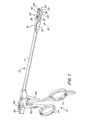
- FIG. 1 is a perspective view of one embodiment of the suture passing instrument of the present invention.
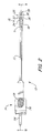
- FIG. 2 is a top view of one embodiment of the suture passing instrument of the present invention.
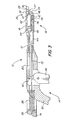
- FIG. 3 is a sectional side view of one embodiment of the suture passing instrument of the present invention, taken along line B.
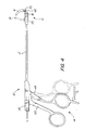
- FIG. 4 is a side view of one embodiment of the suture passing instrument of the present invention.
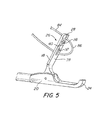
- FIG. 5 is a perspective view of the jaw portion of one embodiment of the suture passing instrument of the present invention.
- FIG. 6 is a perspective view of the jaw portion of one embodiment of the suture passing instrument of the present invention.
- FIG. 7 is a perspective view of the jaw portion of one embodiment of the suture passing instrument of the present invention.
- FIG. 8 is a perspective view of the jaw portion of one embodiment of the suture passing instrument of the present invention.
- FIG. 9 is a perspective view of the jaw portion of one embodiment of the suture passing instrument of the present invention.
- Suture passing instrument 10 includes a shaft 12 connecting a proximally disposed handle portion 14 to a distally disposed jaw portion 16.
- Shaft 12 may be semi-rigid or hinged along its length so that it can be bent or angled once the suture passing instrument 10 is inserted in a trocar (not shown). This allows a user to adjust the jaw portion 16 at different angles to reach the desired area.
- Jaw portion 16 includes an upper jaw 18 pivotally connected to a stationary lower jaw 20, which may be formed integral with the shaft 12. Alternatively, upper jaw 18 may be pivotally connected directly to the shaft 12.
- the distal end 22 of lower jaw 20 is provided as a curved portion 24.
- upper jaw 18 includes a holder 26, which comprises at least one slot, for supporting a suture (not shown).
- the holder 26 comprises a first slot 28 formed on the distal edge 30 of the upper jaw 18 and a second slot 32 formed on an adjacent edge 34.
- Second slot 32 may be provided in the shape of a "T", having bar 36, which aids in supporting the suture within the holder.
- An opening 38 is also provided on second slot 32, the utility of which will be described below.
- bar 36 and the first slot 28 both lie along an axis A. More preferably, bar 36, first slot 28, and opening 38 all lie along axis A.
- Axis A may, but need not, be the same as axis B, which bisects shaft 12.
- the inner surface 39 of upper jaw 18 may also be provided with a plurality of ridges 40 to aid in gripping tissue between the jaws.
- Suture passing instrument 10 also comprises a needle 42.
- needle 42 is flexible and may be composed of spring stainless steel or nitinol.
- needle 42 is provided with a sharp tip 90 for piercing tissue and a hook 92 on an edge for capturing a suture, as will be described below.
- Needle 42 is disposed within an internal channel 44 which runs the length of shaft 12 and continues into the lower jaw 20.
- internal channel 44 is provided with a ramp 46, the utility of which will be explained below.
- multiple needles may be disposed within internal channel 44, or individually within multiple channels. Accordingly, upper jaw 18 would be provided with multiple holders for supporting a suture so that multiple suture loops could be passed at one time.
- Handle portion 14 comprises a trigger arm 48 and a stationary arm 50, both terminating in finger grips 52, 54, and a spring loaded push button 56.
- Spring 58 biases push button 56 in an inactive position.
- a first actuator 60 is coupled at a proximal end 62 to trigger arm 48 and at a distal end 64 to upper jaw 18.
- trigger arm 48 is moved in the direction of arrow A (shown in Figure 4 )
- upper jaw 18 pivots around pivot point 66 in the direction of arrow B from an open position 68 to a closed position 70.
- This allows for a user to grasp an object, namely tissue, between the jaws 18, 20 by squeezing trigger arm 48.
- the ample clearance provided when upper jaw 18 is in the open position 68 allows a user to grasp tissue of many thicknesses.
- a second actuator 72 is coupled at a proximal end 74 to push button 56 and at a distal end 76 to needle 42. Depressing push button 56 in the direction of arrow C, distally advances needle 42 from a recessed position 78 (shown in Figure 3 ) to an extended position 80 (shown in Figure 4 ), where it extends out of outlet 82 to channel 44. Ramp 46 deflects needle 42 so that it exits channel 44 transverse of the shaft 12. As shown in Figure 3 , outlet 82 is vertically aligned with opening 38 when upper jaw 18 is in its closed position 70. Thus, when needle 42 is in its extended position, it extends into opening 38. Both first 60 and second 72 actuators are disposed within internal channel 44.
- a user can grasp the instrument and actuate trigger arm 52 with the fingers of one hand through finger loops 52, 54, leaving the thumb free to actuate push button 56 so that only one hand is necessary to operate the instrument. This leaves the user's other hand free to manipulate the suture threaded in the tissue or to perform other tasks.
- a suture 84 is first loaded into holder 26 by sliding it into first 28 and second 32 slots, as shown in Figure 5 , so that a portion 86 of suture 84 lies across the inner surface 39 of upper jaw 18.
- bar 36, first slot 28, and opening 38 preferably lie along a single axis A so that suture portion 86 lies squarely across opening 38.
- Jaws 18, 20 are then placed on either side of tissue 88 intended to be sutured.
- Upper jaw 18 is moved into a closed position 70, as shown in Figure 6 , clamping the tissue 88 between the lower and upper jaws.
- Needle 42 is advanced to its extended position 80, piercing tissue 88 as it passes through outlet 82 and into opening 34, passing by suture portion 86 (shown in Figure 7 ).
- needle 42 then withdraws back through opening 38 and hook 92 catches suture portion 86.
- suture portion 86 is threaded through tissue 88 forming a suture loop 94. The suture portion 86 is held by the hook 92 against the distal end 22 of lower jaw 20 as the user opens the jaws 18, 20 to release the tissue 88.
- suture 84 The trailing ends of suture 84 are then released from holder 26 and the suture loop 94 is released by advancing needle 42 until the suture can clear the hook 92 ( Figure 9 ). If desired, the user may pull one side of the suture loop 94 through the tissue 88 so that one end of the suture lies on either side of the tissue.
- the length and configuration of the needle 42 is such that it only passes into opening 34 far enough to capture suture portion 86. If needle 42 were allowed to advance such that all of hook 92 extended through opening 34, it would be more likely to capture another portion of suture 84 in addition to suture portion 86. This would cause the suture 84 to become tangled and or for more than one suture portion to be passed through the tissue, which is undesirable.
Landscapes
- Health & Medical Sciences (AREA)
- Life Sciences & Earth Sciences (AREA)
- Surgery (AREA)
- Heart & Thoracic Surgery (AREA)
- Engineering & Computer Science (AREA)
- Biomedical Technology (AREA)
- Nuclear Medicine, Radiotherapy & Molecular Imaging (AREA)
- Medical Informatics (AREA)
- Molecular Biology (AREA)
- Animal Behavior & Ethology (AREA)
- General Health & Medical Sciences (AREA)
- Public Health (AREA)
- Veterinary Medicine (AREA)
- Surgical Instruments (AREA)
Abstract
Description
- The invention relates to suture passing surgical instruments. More specifically, the invention relates to a hand instrument and method for passing suture through tissue.
- Arthroscopic surgery often requires a surgeon to attach a length of suture material remotely to an internal body part. For example, a suture is passed through a detached tendon and is then secured to a hole or anchored in a bone. Various instruments have been developed for this purpose, many of them having an elongate configuration and low profile for facilitating use through cannulas in less invasive surgery. These devices have also typically have opposing jaws, which clamp onto either side of the tissue to be sutured. However, the various known mechanisms and configurations for loading the suture, grasping the suture, and threading a suture between the jaws shown in these prior art devices are exceedingly complex. Moreover, due to this complexity and poor design, in general, these devices have a tendency to create tangles in the suture or to simply fail to pass the suture through the tissue as intended. Many of these devices may also require the use of both hands to operate the instrument.
- What is desired, therefore, is a suture passing device having a low profile that can accommodate many thicknesses of tissue, is easy to load with a suture and utilizes a mechanism that is easy and reliable for threading the suture through tissue.
- Accordingly, it is an object of the present invention to provide a suture passing instrument that is of simple configuration so that a suture may be loaded into the instrument with relative ease. It is a further object of the present invention to provide a suture passing instrument having wide opening jaws so that it may be used with a range of tissue thickness. It is a further object of the invention to provide a suture passing instrument which prevents tangling of the suture and only threads one loop of suture through the tissue as desired. A further object of the invention is to provide a suture passing instrument which may be operated with one hand.
- These and other objectives are achieved by providing a suture passing instrument comprising a first jaw coupled to an end of an elongated shaft, a second jaw coupled to the first jaw, and formed with a holder for supporting a suture, and a needle slidably disposed within the first jaw, the needle having a hook on a side for releasably capturing a portion of a suture. The first jaw defines a channel for receiving the needle and a ramp for deflecting the needle transversely of the shaft when advanced to an extended position. In some embodiments, the first jaw is stationary and the second jaw is movable and may be pivotally coupled to the first jaw. The needle may be made from a malleable material and may have a sharp distal tip for piercing tissue. An opening may also be formed in the second jaw that provides a clearance for a tip portion of the needle to pass when it is advanced to its extended position.
- In some embodiments, the opening and the holder may be aligned such that a suture received in the holder extends across the opening. In further embodiments, the holder supports the suture on an inner surface of the movable jaw facing the stationary jaw. The holder may comprise at least one slot formed on an edge of the movable jaw which, in further embodiments, may comprise a first slot formed on a distal edge of the movable jaw and a second slot formed on an adjacent edge of the movable jaw. The second slot may be T-shaped. In further embodiments, a plurality of needles may be slidably disposed within the first jaw. In yet further embodiments, the elongated shaft may be semi-rigid or hinged.
- Other objects of the present invention are achieved by provision of a suture passing instrument comprising a stationary jaw coupled to an elongated shaft, a malleable needle slidably disposed within the stationary jaw, the needle having a distal tip and a hook on an edge for releasably capturing a portion of a suture, a movable jaw pivotally coupled to the stationary jaw, and formed with a holder for supporting a suture and an opening that provides a clearance through which a tip portion of the needle passes when in its extended position, a first actuating member coupled to the movable jaw for moving it between a closed position alongside the stationary jaw and an open position spaced therefrom, and a second actuating member coupled to said needle for moving the needle between a recessed position and an extended position wherein the distal tip of the needle is deflected by the ramp and extends out of the stationary jaw transversely of the shaft such that the needle tip enters the opening in the movable jaw and the needle hook captures a portion of the suture supported in the holder. The stationary jaw may define an internal channel for receiving the needle and a distal ramp.
- Other objects of the present invention are achieved by provision of a method of passing suture comprising the steps of providing a suture passing instrument having a first jaw coupled to an elongated shaft, a second jaw coupled to the first jaw, and formed with a holder for supporting a suture, and a needle slidably disposed within the first jaw, the needle having a hook on a side for capturing a portion of a suture; loading a suture into the holder of said second jaw; grasping tissue between said first jaw and second jaw; and passing suture through said tissue by advancing said needle to its extended position, capturing a portion of the suture supported in the holder with the hook, and returning the needle to a recessed position so that a loop of the suture portion captured by the needle is drawn through the tissue. The first jaw may define a channel for receiving the needle and a distal ramp for deflecting the needle transversely of the shaft when advanced to an extended position.
- In some embodiments, the step of grasping tissue between the first jaw and second jaw further includes actuating a first actuating member displaced within the shaft and coupled to the second jaw such that the second jaw pivots toward the first jaw to grasp tissue therebetween. In further embodiments, the step of advancing the needle further includes actuating a second actuating member displaced within the shaft and coupled to the needle such that the distal tip of the needle is advanced proximally, is deflected by the ramp and extends out of the first jaw transversely of the shaft. The step of advancing the needle may include advancing the needle through tissue. In still further embodiments, the step of advancing the needle includes advancing the needle such that the needle tip enters the opening in the second jaw.
- Other objects of the invention and its particular features and advantages will become more apparent from consideration of the following drawings and accompanying detailed description.
-
FIG. 1 is a perspective view of one embodiment of the suture passing instrument of the present invention. -
FIG. 2 is a top view of one embodiment of the suture passing instrument of the present invention. -
FIG. 3 is a sectional side view of one embodiment of the suture passing instrument of the present invention, taken along line B. -
FIG. 4 is a side view of one embodiment of the suture passing instrument of the present invention. -
FIG. 5 is a perspective view of the jaw portion of one embodiment of the suture passing instrument of the present invention. -
FIG. 6 is a perspective view of the jaw portion of one embodiment of the suture passing instrument of the present invention. -
FIG. 7 is a perspective view of the jaw portion of one embodiment of the suture passing instrument of the present invention. -
FIG. 8 is a perspective view of the jaw portion of one embodiment of the suture passing instrument of the present invention. -
FIG. 9 is a perspective view of the jaw portion of one embodiment of the suture passing instrument of the present invention. - One embodiment of the
suture passing instrument 10 of the present invention is shown inFigure 1 .Suture passing instrument 10 includes ashaft 12 connecting a proximally disposedhandle portion 14 to a distally disposedjaw portion 16.Shaft 12 may be semi-rigid or hinged along its length so that it can be bent or angled once thesuture passing instrument 10 is inserted in a trocar (not shown). This allows a user to adjust thejaw portion 16 at different angles to reach the desired area.Jaw portion 16 includes anupper jaw 18 pivotally connected to a stationarylower jaw 20, which may be formed integral with theshaft 12. Alternatively,upper jaw 18 may be pivotally connected directly to theshaft 12. Thedistal end 22 oflower jaw 20 is provided as acurved portion 24. - As shown in
Figures 2 and3 ,upper jaw 18 includes aholder 26, which comprises at least one slot, for supporting a suture (not shown). In the present embodiment, theholder 26 comprises afirst slot 28 formed on thedistal edge 30 of theupper jaw 18 and asecond slot 32 formed on anadjacent edge 34.Second slot 32 may be provided in the shape of a "T", havingbar 36, which aids in supporting the suture within the holder. Anopening 38 is also provided onsecond slot 32, the utility of which will be described below. Preferably,bar 36 and thefirst slot 28 both lie along an axis A. More preferably,bar 36,first slot 28, and opening 38 all lie along axis A. Axis A may, but need not, be the same as axis B, which bisectsshaft 12. Theinner surface 39 ofupper jaw 18 may also be provided with a plurality ofridges 40 to aid in gripping tissue between the jaws. - Suture
passing instrument 10 also comprises aneedle 42. Preferably,needle 42 is flexible and may be composed of spring stainless steel or nitinol. Depicted inFigure 7 ,needle 42 is provided with asharp tip 90 for piercing tissue and ahook 92 on an edge for capturing a suture, as will be described below.Needle 42 is disposed within aninternal channel 44 which runs the length ofshaft 12 and continues into thelower jaw 20. Corresponding to thecurved portion 24 oflower jaw 20,internal channel 44 is provided with aramp 46, the utility of which will be explained below. In additional embodiments, multiple needles may be disposed withininternal channel 44, or individually within multiple channels. Accordingly,upper jaw 18 would be provided with multiple holders for supporting a suture so that multiple suture loops could be passed at one time. -
Handle portion 14 comprises atrigger arm 48 and astationary arm 50, both terminating in finger grips 52, 54, and a spring loadedpush button 56.Spring 58 biases pushbutton 56 in an inactive position. As shown inFigure 3 , afirst actuator 60 is coupled at aproximal end 62 to triggerarm 48 and at adistal end 64 toupper jaw 18. Whentrigger arm 48 is moved in the direction of arrow A (shown inFigure 4 ),upper jaw 18 pivots aroundpivot point 66 in the direction of arrow B from an open position 68 to aclosed position 70. This allows for a user to grasp an object, namely tissue, between thejaws trigger arm 48. Moreover, the ample clearance provided whenupper jaw 18 is in the open position 68 allows a user to grasp tissue of many thicknesses. - A
second actuator 72 is coupled at aproximal end 74 to pushbutton 56 and at adistal end 76 toneedle 42.Depressing push button 56 in the direction of arrow C, distally advancesneedle 42 from a recessed position 78 (shown inFigure 3 ) to an extended position 80 (shown inFigure 4 ), where it extends out ofoutlet 82 tochannel 44.Ramp 46 deflectsneedle 42 so that it exitschannel 44 transverse of theshaft 12. As shown inFigure 3 ,outlet 82 is vertically aligned with opening 38 whenupper jaw 18 is in itsclosed position 70. Thus, whenneedle 42 is in its extended position, it extends intoopening 38. Both first 60 and second 72 actuators are disposed withininternal channel 44. - Notably, a user can grasp the instrument and actuate
trigger arm 52 with the fingers of one hand throughfinger loops push button 56 so that only one hand is necessary to operate the instrument. This leaves the user's other hand free to manipulate the suture threaded in the tissue or to perform other tasks. - In operation, a
suture 84 is first loaded intoholder 26 by sliding it into first 28 and second 32 slots, as shown inFigure 5 , so that aportion 86 ofsuture 84 lies across theinner surface 39 ofupper jaw 18. As noted above,bar 36,first slot 28, and opening 38 preferably lie along a single axis A so thatsuture portion 86 lies squarely acrossopening 38.Jaws tissue 88 intended to be sutured.Upper jaw 18 is moved into aclosed position 70, as shown inFigure 6 , clamping thetissue 88 between the lower and upper jaws. -
Needle 42 is advanced to itsextended position 80, piercingtissue 88 as it passes throughoutlet 82 and intoopening 34, passing by suture portion 86 (shown inFigure 7 ). Whenpush button 56 is released,needle 42 then withdraws back throughopening 38 andhook 92 catches sutureportion 86. As shown inFigure 8 , asneedle 42 continues to recede in a proximal direction,suture portion 86 is threaded throughtissue 88 forming a suture loop 94. Thesuture portion 86 is held by thehook 92 against thedistal end 22 oflower jaw 20 as the user opens thejaws tissue 88. The trailing ends ofsuture 84 are then released fromholder 26 and the suture loop 94 is released by advancingneedle 42 until the suture can clear the hook 92 (Figure 9 ). If desired, the user may pull one side of the suture loop 94 through thetissue 88 so that one end of the suture lies on either side of the tissue. - Notably, the length and configuration of the
needle 42 is such that it only passes into opening 34 far enough to capturesuture portion 86. Ifneedle 42 were allowed to advance such that all ofhook 92 extended throughopening 34, it would be more likely to capture another portion ofsuture 84 in addition tosuture portion 86. This would cause thesuture 84 to become tangled and or for more than one suture portion to be passed through the tissue, which is undesirable. - It should be understood that the foregoing is illustrative and not limiting, and that obvious modifications may be made by those skilled in the art without departing from the spirit of the invention. Accordingly, reference should be made primarily to the accompanying claims, rather than the foregoing specification, to determine the scope of the invention.
Claims (15)
- A suture passing instrument comprising:a first jaw coupled to an end of an elongated shaft;a second jaw coupled to the first jaw, and formed with a holder for supporting a suture; anda needle slidably disposed within the first jaw, said needle having a hook on a side for releasably capturing a portion of a suture;said first jaw defining a channel for receiving said needle and a ramp for deflecting the needle transversely of the shaft when advanced to an extended position.
- The suture passing instrument of claim 1 wherein said first jaw is stationary.
- The suture passing instrument of claim 1 wherein said second jaw is pivotally coupled to the first jaw.
- The suture passing instrument of claim 1 wherein said needle is made from a malleable material.
- The suture passing instrument of claim 1 wherein said needle has a sharp distal tip for piercing tissue.
- The suture passing instrument of claim 1 wherein the first jaw and second jaw are configured to receive tissue therebetween.
- The suture passing instrument of claim 1 further comprising an opening formed in the second jaw that provides a clearance through which a tip portion of the needle passes when it is advanced to its extended position.
- The suture passing instrument of claim 7 wherein said opening and said holder are aligned such that a suture received in the holder extends across the opening.
- The suture passing instrument of claim 7 wherein said hook does not pass completely through said opening when said needle is advanced to its extended position.
- The suture passing instrument of claim 1 wherein said holder supports said suture on an inner surface of the second jaw facing the first jaw.
- The suture passing instrument of claim 1 wherein said holder comprises at least one slot formed on an edge of said second jaw.
- The suture passing instrument of claim 11 wherein said holder comprises a first slot formed on a distal edge of said second jaw and a second slot formed on an adjacent edge of said second jaw.
- The suture passing instrument of claim 12 wherein said second slot is T-shaped.
- The suture passing instrument of claim 1 further comprising a first actuating member displaced within said shaft and coupled to the second jaw for moving it between a closed position alongside said first jaw and an open position spaced therefrom.
- The suture passing instrument of claim 1 further comprising a second actuating member displaced within said shaft and coupled to said needle for moving said needle between a recessed position and its extended position.
Applications Claiming Priority (1)
| Application Number | Priority Date | Filing Date | Title |
|---|---|---|---|
| US12/473,998 US8282656B2 (en) | 2009-05-28 | 2009-05-28 | Suture passing instrument |
Publications (2)
| Publication Number | Publication Date |
|---|---|
| EP2255733A1 true EP2255733A1 (en) | 2010-12-01 |
| EP2255733B1 EP2255733B1 (en) | 2013-01-30 |
Family
ID=42732442
Family Applications (1)
| Application Number | Title | Priority Date | Filing Date |
|---|---|---|---|
| EP10164237A Active EP2255733B1 (en) | 2009-05-28 | 2010-05-28 | Suture passing instrument |
Country Status (2)
| Country | Link |
|---|---|
| US (1) | US8282656B2 (en) |
| EP (1) | EP2255733B1 (en) |
Cited By (8)
| Publication number | Priority date | Publication date | Assignee | Title |
|---|---|---|---|---|
| WO2013033373A1 (en) * | 2011-09-02 | 2013-03-07 | Boston Scientific Scimed, Inc. | A multi-arm tool for delivering implants |
| US9271754B2 (en) | 2010-12-16 | 2016-03-01 | Boston Scientific Scimed, Inc. | Movable curved needle for delivering implants and methods of delivering implants |
| EP3031402A4 (en) * | 2013-08-06 | 2017-04-05 | Olympus Corporation | Suture device |
| US9763763B2 (en) | 2011-03-10 | 2017-09-19 | Boston Scientific Scimed, Inc. | Multi-arm inside-out tool for delivering implants and methods thereof |
| CN108814666A (en) * | 2013-11-18 | 2018-11-16 | 爱德华兹生命科学股份公司 | Repeatedly percussion compression bonding apparatus |
| CN109199485A (en) * | 2017-06-29 | 2019-01-15 | 美多斯国际有限公司 | The suture wire box of surgical device is connected for suture |
| CN110547851A (en) * | 2013-04-17 | 2019-12-10 | 马鲁霍医药有限公司 | Method and apparatus for passing suture |
| US20220249087A1 (en) * | 2019-07-22 | 2022-08-11 | Smith & Nephew, Inc. | Suture passers |
Families Citing this family (37)
| Publication number | Priority date | Publication date | Assignee | Title |
|---|---|---|---|---|
| US8465505B2 (en) | 2011-05-06 | 2013-06-18 | Ceterix Orthopaedics, Inc. | Suture passer devices and methods |
| US8911456B2 (en) | 2007-07-03 | 2014-12-16 | Ceterix Orthopaedics, Inc. | Methods and devices for preventing tissue bridging while suturing |
| US9211119B2 (en) | 2007-07-03 | 2015-12-15 | Ceterix Orthopaedics, Inc. | Suture passers and methods of passing suture |
| US9314234B2 (en) | 2007-07-03 | 2016-04-19 | Ceterix Orthopaedics, Inc. | Pre-tied surgical knots for use with suture passers |
| US8702731B2 (en) | 2007-07-03 | 2014-04-22 | Ceterix Orthopaedics, Inc. | Suturing and repairing tissue using in vivo suture loading |
| US10441273B2 (en) | 2007-07-03 | 2019-10-15 | Ceterix Orthopaedics, Inc. | Pre-tied surgical knots for use with suture passers |
| US8663253B2 (en) | 2007-07-03 | 2014-03-04 | Ceterix Orthopaedics, Inc. | Methods of meniscus repair |
| US8500809B2 (en) | 2011-01-10 | 2013-08-06 | Ceterix Orthopaedics, Inc. | Implant and method for repair of the anterior cruciate ligament |
| US9861354B2 (en) * | 2011-05-06 | 2018-01-09 | Ceterix Orthopaedics, Inc. | Meniscus repair |
| US11744575B2 (en) | 2009-11-09 | 2023-09-05 | Ceterix Orthopaedics, Inc. | Suture passer devices and methods |
| JP5719374B2 (en) | 2009-11-09 | 2015-05-20 | セテリックス オーソピーディクス インコーポレイテッド | Device, system, and method for repairing a meniscus |
| US9011454B2 (en) | 2009-11-09 | 2015-04-21 | Ceterix Orthopaedics, Inc. | Suture passer with radiused upper jaw |
| US9848868B2 (en) | 2011-01-10 | 2017-12-26 | Ceterix Orthopaedics, Inc. | Suture methods for forming locking loops stitches |
| US8940000B2 (en) * | 2010-05-12 | 2015-01-27 | Covidien Lp | Surgical instruments with flexible member attachment structures |
| US9913638B2 (en) | 2011-01-10 | 2018-03-13 | Ceterix Orthopaedics, Inc. | Transosteal anchoring methods for tissue repair |
| US9351723B2 (en) * | 2011-06-30 | 2016-05-31 | Astora Women's Health, Llc | Implants, tools, and methods for treatments of pelvic conditions |
| US9662105B2 (en) | 2011-07-08 | 2017-05-30 | Smith & Nephew, Inc. | Suture passer and method |
| US9357997B2 (en) | 2011-07-08 | 2016-06-07 | Smith & Nephew, Inc. | Suture passer and method |
| US8882834B2 (en) | 2011-07-08 | 2014-11-11 | Smith & Nephew, Inc. | Soft tissue repair |
| US10524778B2 (en) | 2011-09-28 | 2020-01-07 | Ceterix Orthopaedics | Suture passers adapted for use in constrained regions |
| US20140155914A1 (en) * | 2012-08-03 | 2014-06-05 | David James Schneider | Devices and methods for passing sutures through tissue |
| BR302013006577S1 (en) * | 2013-06-27 | 2015-03-10 | Storz Karl Gmbh & Co Kg | CONFIGURATION APPLIED IN MEDICAL INSTRUMENT |
| US20150012016A1 (en) * | 2013-07-03 | 2015-01-08 | Biomet Manufacturing, Llc | Suture passer |
| US9247935B2 (en) | 2013-09-23 | 2016-02-02 | Ceterix Orthopaedics, Inc. | Arthroscopic knot pusher and suture cutter |
| WO2015095133A1 (en) | 2013-12-16 | 2015-06-25 | Ceterix Orthopaedics, Inc. | Automatically reloading suture passer devices having pre-tied knots and methods |
| US9687225B2 (en) * | 2013-12-20 | 2017-06-27 | Biomet Sports Medicine, Llc | Suture passer with tissue reinforcement positioner |
| USD759815S1 (en) * | 2014-03-24 | 2016-06-21 | Karl Storz Gmbh & Co. Kg | Cholangiography catheter guide |
| CN105250001B (en) | 2014-04-08 | 2019-07-12 | 赛特里克斯整形公司 | Suitable for suture passer used in confined area |
| US9895153B2 (en) * | 2014-07-01 | 2018-02-20 | Boston Scientific Scimed, Inc. | Hemostatic clip with needle passer |
| US10226245B2 (en) | 2015-07-21 | 2019-03-12 | Ceterix Orthopaedics, Inc. | Automatically reloading suture passer devices that prevent entanglement |
| US10405853B2 (en) | 2015-10-02 | 2019-09-10 | Ceterix Orthpaedics, Inc. | Knot tying accessory |
| CA3057602C (en) | 2017-06-30 | 2021-10-26 | Wright Medical Technology, Inc. | Soft tissue repair instruments and techniques |
| DE202018101753U1 (en) * | 2018-03-28 | 2018-05-08 | Tuebingen Scientific Medical Gmbh | Electrode application instrument |
| US20250017719A1 (en) | 2023-07-12 | 2025-01-16 | Integrity Medical Services Inc. | Tissue repair devices, systems, and methods |
| CN118285586A (en) * | 2024-05-09 | 2024-07-05 | 浙江嘉欣金三塔丝绸服饰有限公司 | Rope threading device |
| US12594097B2 (en) * | 2024-05-31 | 2026-04-07 | Integrity Medical Services Inc. | Systems and methods for orthopedic tool connectors |
| US20250366850A1 (en) | 2024-05-31 | 2025-12-04 | Integrity Medical Services Inc. | Systems and methods for surgical tissue repair |
Citations (2)
| Publication number | Priority date | Publication date | Assignee | Title |
|---|---|---|---|---|
| US20070270885A1 (en) * | 2001-10-01 | 2007-11-22 | Depuy Mitek, Inc., A Massachusetts Corporation | Suturing apparatus and method |
| US20080097482A1 (en) * | 2006-10-24 | 2008-04-24 | Gregory Bain | Suture device having selective needle actuation and related method |
Family Cites Families (12)
| Publication number | Priority date | Publication date | Assignee | Title |
|---|---|---|---|---|
| US1856721A (en) | 1931-02-07 | 1932-05-03 | Clemens B Nagelmann | Suturing and ligating instrument |
| US4164225A (en) | 1977-12-28 | 1979-08-14 | Johnson & Lorenz, Inc. | Surgical suturing instrument |
| US4596249A (en) | 1983-07-26 | 1986-06-24 | Freda Vincent J | Implement for setting sutures |
| US5776150A (en) * | 1996-06-10 | 1998-07-07 | Ethicon Endo Surgery, Inc. | Suture assist device |
| AT408832B (en) | 1997-09-09 | 2002-03-25 | Werner Ing Fuchs | SURGICAL SEWING PLIERS |
| US6217592B1 (en) | 1998-10-06 | 2001-04-17 | Vincent Freda | Laproscopic instrument for suturing tissue |
| DE60230084D1 (en) * | 2001-03-23 | 2009-01-15 | Arthrex Inc | Instrument for pulling a thread during arthroscopic suturing of tissue |
| US7112208B2 (en) | 2001-08-06 | 2006-09-26 | Morris John K | Compact suture punch with malleable needle |
| ATE545370T1 (en) * | 2001-10-01 | 2012-03-15 | Depuy Mitek Inc | SEWING APPARATUS |
| EP1306056B1 (en) | 2001-10-23 | 2006-05-24 | Arthrex, Inc. | Tissue suturing instrument |
| US6984237B2 (en) | 2002-05-22 | 2006-01-10 | Orthopaedic Biosystems Ltd., Inc. | Suture passing surgical instrument |
| US6770084B1 (en) | 2002-06-26 | 2004-08-03 | Opus Medical, Inc. | Suture capture device |
-
2009
- 2009-05-28 US US12/473,998 patent/US8282656B2/en active Active
-
2010
- 2010-05-28 EP EP10164237A patent/EP2255733B1/en active Active
Patent Citations (2)
| Publication number | Priority date | Publication date | Assignee | Title |
|---|---|---|---|---|
| US20070270885A1 (en) * | 2001-10-01 | 2007-11-22 | Depuy Mitek, Inc., A Massachusetts Corporation | Suturing apparatus and method |
| US20080097482A1 (en) * | 2006-10-24 | 2008-04-24 | Gregory Bain | Suture device having selective needle actuation and related method |
Cited By (14)
| Publication number | Priority date | Publication date | Assignee | Title |
|---|---|---|---|---|
| US9271754B2 (en) | 2010-12-16 | 2016-03-01 | Boston Scientific Scimed, Inc. | Movable curved needle for delivering implants and methods of delivering implants |
| US9763763B2 (en) | 2011-03-10 | 2017-09-19 | Boston Scientific Scimed, Inc. | Multi-arm inside-out tool for delivering implants and methods thereof |
| US10314572B2 (en) | 2011-09-02 | 2019-06-11 | Boston Scientific Scimed, Inc. | Multi-arm tool for delivering implants and methods thereof |
| US9345472B2 (en) | 2011-09-02 | 2016-05-24 | Boston Scientific Scimed, Inc. | Multi-arm tool for delivering implants and methods thereof |
| WO2013033373A1 (en) * | 2011-09-02 | 2013-03-07 | Boston Scientific Scimed, Inc. | A multi-arm tool for delivering implants |
| US11523816B2 (en) | 2013-04-17 | 2022-12-13 | Maruho Medical, Inc. | Method and apparatus for passing suture |
| CN110547851A (en) * | 2013-04-17 | 2019-12-10 | 马鲁霍医药有限公司 | Method and apparatus for passing suture |
| EP3031402A4 (en) * | 2013-08-06 | 2017-04-05 | Olympus Corporation | Suture device |
| US9693769B2 (en) | 2013-08-06 | 2017-07-04 | Olympus Corporation | Suture device |
| CN108814666A (en) * | 2013-11-18 | 2018-11-16 | 爱德华兹生命科学股份公司 | Repeatedly percussion compression bonding apparatus |
| CN108814666B (en) * | 2013-11-18 | 2021-04-13 | 爱德华兹生命科学股份公司 | Multi-firing crimping device |
| CN109199485A (en) * | 2017-06-29 | 2019-01-15 | 美多斯国际有限公司 | The suture wire box of surgical device is connected for suture |
| CN109199485B (en) * | 2017-06-29 | 2023-10-31 | 美多斯国际有限公司 | Suture cassette for suture passable surgical devices |
| US20220249087A1 (en) * | 2019-07-22 | 2022-08-11 | Smith & Nephew, Inc. | Suture passers |
Also Published As
| Publication number | Publication date |
|---|---|
| US8282656B2 (en) | 2012-10-09 |
| EP2255733B1 (en) | 2013-01-30 |
| US20100305581A1 (en) | 2010-12-02 |
Similar Documents
| Publication | Publication Date | Title |
|---|---|---|
| US8282656B2 (en) | Suture passing instrument | |
| US11766253B2 (en) | Automatically reloading suture passer devices and methods | |
| EP1958574B1 (en) | Suture passing instrument | |
| EP2177167B1 (en) | Suturing apparatus | |
| US7585305B2 (en) | Suture passing instrument | |
| US6896686B2 (en) | Arthroscopic suture passing instrument | |
| CA2809752C (en) | Suturing apparatus and method | |
| US6936054B2 (en) | Placing sutures | |
| EP2184015B1 (en) | Suturing instrument for passing multiple sutures | |
| EP2033583B1 (en) | In-line suture passer | |
| US8852088B2 (en) | Tissue retractor assembly | |
| US20080027468A1 (en) | Suture needle, suture needle/suture assembly and suture passer device | |
| US10485532B2 (en) | Suture passer device including a blunt tip and a sharp tip | |
| EP2238919A2 (en) | Endoscopic apparatus for manipulating tissue | |
| US20160206391A1 (en) | A system to manipulate organs and instruments for minimally invasive surgery | |
| US20240032911A1 (en) | Automatically reloading suture passer devices and methods | |
| NL2019974B1 (en) | Suture device | |
| EP2282678B1 (en) | A remote control mechanism for atraumatic surgical needle |
Legal Events
| Date | Code | Title | Description |
|---|---|---|---|
| PUAI | Public reference made under article 153(3) epc to a published international application that has entered the european phase |
Free format text: ORIGINAL CODE: 0009012 |
|
| AK | Designated contracting states |
Kind code of ref document: A1 Designated state(s): AL AT BE BG CH CY CZ DE DK EE ES FI FR GB GR HR HU IE IS IT LI LT LU LV MC MK MT NL NO PL PT RO SE SI SK SM TR |
|
| AX | Request for extension of the european patent |
Extension state: BA ME RS |
|
| 17P | Request for examination filed |
Effective date: 20110531 |
|
| 17Q | First examination report despatched |
Effective date: 20120117 |
|
| GRAP | Despatch of communication of intention to grant a patent |
Free format text: ORIGINAL CODE: EPIDOSNIGR1 |
|
| GRAS | Grant fee paid |
Free format text: ORIGINAL CODE: EPIDOSNIGR3 |
|
| GRAA | (expected) grant |
Free format text: ORIGINAL CODE: 0009210 |
|
| AK | Designated contracting states |
Kind code of ref document: B1 Designated state(s): AL AT BE BG CH CY CZ DE DK EE ES FI FR GB GR HR HU IE IS IT LI LT LU LV MC MK MT NL NO PL PT RO SE SI SK SM TR |
|
| REG | Reference to a national code |
Ref country code: GB Ref legal event code: FG4D |
|
| REG | Reference to a national code |
Ref country code: CH Ref legal event code: EP |
|
| REG | Reference to a national code |
Ref country code: AT Ref legal event code: REF Ref document number: 595556 Country of ref document: AT Kind code of ref document: T Effective date: 20130215 Ref country code: CH Ref legal event code: EP |
|
| REG | Reference to a national code |
Ref country code: IE Ref legal event code: FG4D |
|
| REG | Reference to a national code |
Ref country code: DE Ref legal event code: R096 Ref document number: 602010004880 Country of ref document: DE Effective date: 20130321 |
|
| REG | Reference to a national code |
Ref country code: AT Ref legal event code: MK05 Ref document number: 595556 Country of ref document: AT Kind code of ref document: T Effective date: 20130130 |
|
| REG | Reference to a national code |
Ref country code: LT Ref legal event code: MG4D |
|
| REG | Reference to a national code |
Ref country code: NL Ref legal event code: VDEP Effective date: 20130130 |
|
| PG25 | Lapsed in a contracting state [announced via postgrant information from national office to epo] |
Ref country code: AT Free format text: LAPSE BECAUSE OF FAILURE TO SUBMIT A TRANSLATION OF THE DESCRIPTION OR TO PAY THE FEE WITHIN THE PRESCRIBED TIME-LIMIT Effective date: 20130130 Ref country code: NO Free format text: LAPSE BECAUSE OF FAILURE TO SUBMIT A TRANSLATION OF THE DESCRIPTION OR TO PAY THE FEE WITHIN THE PRESCRIBED TIME-LIMIT Effective date: 20130430 Ref country code: LT Free format text: LAPSE BECAUSE OF FAILURE TO SUBMIT A TRANSLATION OF THE DESCRIPTION OR TO PAY THE FEE WITHIN THE PRESCRIBED TIME-LIMIT Effective date: 20130130 Ref country code: IS Free format text: LAPSE BECAUSE OF FAILURE TO SUBMIT A TRANSLATION OF THE DESCRIPTION OR TO PAY THE FEE WITHIN THE PRESCRIBED TIME-LIMIT Effective date: 20130530 Ref country code: SE Free format text: LAPSE BECAUSE OF FAILURE TO SUBMIT A TRANSLATION OF THE DESCRIPTION OR TO PAY THE FEE WITHIN THE PRESCRIBED TIME-LIMIT Effective date: 20130130 Ref country code: BG Free format text: LAPSE BECAUSE OF FAILURE TO SUBMIT A TRANSLATION OF THE DESCRIPTION OR TO PAY THE FEE WITHIN THE PRESCRIBED TIME-LIMIT Effective date: 20130430 Ref country code: ES Free format text: LAPSE BECAUSE OF FAILURE TO SUBMIT A TRANSLATION OF THE DESCRIPTION OR TO PAY THE FEE WITHIN THE PRESCRIBED TIME-LIMIT Effective date: 20130511 Ref country code: BE Free format text: LAPSE BECAUSE OF FAILURE TO SUBMIT A TRANSLATION OF THE DESCRIPTION OR TO PAY THE FEE WITHIN THE PRESCRIBED TIME-LIMIT Effective date: 20130130 |
|
| PG25 | Lapsed in a contracting state [announced via postgrant information from national office to epo] |
Ref country code: SI Free format text: LAPSE BECAUSE OF FAILURE TO SUBMIT A TRANSLATION OF THE DESCRIPTION OR TO PAY THE FEE WITHIN THE PRESCRIBED TIME-LIMIT Effective date: 20130130 Ref country code: NL Free format text: LAPSE BECAUSE OF FAILURE TO SUBMIT A TRANSLATION OF THE DESCRIPTION OR TO PAY THE FEE WITHIN THE PRESCRIBED TIME-LIMIT Effective date: 20130130 Ref country code: GR Free format text: LAPSE BECAUSE OF FAILURE TO SUBMIT A TRANSLATION OF THE DESCRIPTION OR TO PAY THE FEE WITHIN THE PRESCRIBED TIME-LIMIT Effective date: 20130501 Ref country code: PT Free format text: LAPSE BECAUSE OF FAILURE TO SUBMIT A TRANSLATION OF THE DESCRIPTION OR TO PAY THE FEE WITHIN THE PRESCRIBED TIME-LIMIT Effective date: 20130530 Ref country code: FI Free format text: LAPSE BECAUSE OF FAILURE TO SUBMIT A TRANSLATION OF THE DESCRIPTION OR TO PAY THE FEE WITHIN THE PRESCRIBED TIME-LIMIT Effective date: 20130130 Ref country code: PL Free format text: LAPSE BECAUSE OF FAILURE TO SUBMIT A TRANSLATION OF THE DESCRIPTION OR TO PAY THE FEE WITHIN THE PRESCRIBED TIME-LIMIT Effective date: 20130130 Ref country code: LV Free format text: LAPSE BECAUSE OF FAILURE TO SUBMIT A TRANSLATION OF THE DESCRIPTION OR TO PAY THE FEE WITHIN THE PRESCRIBED TIME-LIMIT Effective date: 20130130 |
|
| PG25 | Lapsed in a contracting state [announced via postgrant information from national office to epo] |
Ref country code: HR Free format text: LAPSE BECAUSE OF FAILURE TO SUBMIT A TRANSLATION OF THE DESCRIPTION OR TO PAY THE FEE WITHIN THE PRESCRIBED TIME-LIMIT Effective date: 20130130 |
|
| PG25 | Lapsed in a contracting state [announced via postgrant information from national office to epo] |
Ref country code: CZ Free format text: LAPSE BECAUSE OF FAILURE TO SUBMIT A TRANSLATION OF THE DESCRIPTION OR TO PAY THE FEE WITHIN THE PRESCRIBED TIME-LIMIT Effective date: 20130130 Ref country code: SK Free format text: LAPSE BECAUSE OF FAILURE TO SUBMIT A TRANSLATION OF THE DESCRIPTION OR TO PAY THE FEE WITHIN THE PRESCRIBED TIME-LIMIT Effective date: 20130130 Ref country code: DK Free format text: LAPSE BECAUSE OF FAILURE TO SUBMIT A TRANSLATION OF THE DESCRIPTION OR TO PAY THE FEE WITHIN THE PRESCRIBED TIME-LIMIT Effective date: 20130130 Ref country code: RO Free format text: LAPSE BECAUSE OF FAILURE TO SUBMIT A TRANSLATION OF THE DESCRIPTION OR TO PAY THE FEE WITHIN THE PRESCRIBED TIME-LIMIT Effective date: 20130130 Ref country code: EE Free format text: LAPSE BECAUSE OF FAILURE TO SUBMIT A TRANSLATION OF THE DESCRIPTION OR TO PAY THE FEE WITHIN THE PRESCRIBED TIME-LIMIT Effective date: 20130130 |
|
| PG25 | Lapsed in a contracting state [announced via postgrant information from national office to epo] |
Ref country code: CY Free format text: LAPSE BECAUSE OF FAILURE TO SUBMIT A TRANSLATION OF THE DESCRIPTION OR TO PAY THE FEE WITHIN THE PRESCRIBED TIME-LIMIT Effective date: 20130130 |
|
| PLBE | No opposition filed within time limit |
Free format text: ORIGINAL CODE: 0009261 |
|
| STAA | Information on the status of an ep patent application or granted ep patent |
Free format text: STATUS: NO OPPOSITION FILED WITHIN TIME LIMIT |
|
| PG25 | Lapsed in a contracting state [announced via postgrant information from national office to epo] |
Ref country code: MC Free format text: LAPSE BECAUSE OF FAILURE TO SUBMIT A TRANSLATION OF THE DESCRIPTION OR TO PAY THE FEE WITHIN THE PRESCRIBED TIME-LIMIT Effective date: 20130130 |
|
| 26N | No opposition filed |
Effective date: 20131031 |
|
| REG | Reference to a national code |
Ref country code: DE Ref legal event code: R097 Ref document number: 602010004880 Country of ref document: DE Effective date: 20131031 |
|
| REG | Reference to a national code |
Ref country code: IE Ref legal event code: MM4A |
|
| PG25 | Lapsed in a contracting state [announced via postgrant information from national office to epo] |
Ref country code: IE Free format text: LAPSE BECAUSE OF NON-PAYMENT OF DUE FEES Effective date: 20130528 |
|
| REG | Reference to a national code |
Ref country code: CH Ref legal event code: PL |
|
| PG25 | Lapsed in a contracting state [announced via postgrant information from national office to epo] |
Ref country code: LI Free format text: LAPSE BECAUSE OF NON-PAYMENT OF DUE FEES Effective date: 20140531 Ref country code: CH Free format text: LAPSE BECAUSE OF NON-PAYMENT OF DUE FEES Effective date: 20140531 |
|
| PG25 | Lapsed in a contracting state [announced via postgrant information from national office to epo] |
Ref country code: MT Free format text: LAPSE BECAUSE OF FAILURE TO SUBMIT A TRANSLATION OF THE DESCRIPTION OR TO PAY THE FEE WITHIN THE PRESCRIBED TIME-LIMIT Effective date: 20130130 |
|
| PG25 | Lapsed in a contracting state [announced via postgrant information from national office to epo] |
Ref country code: SM Free format text: LAPSE BECAUSE OF FAILURE TO SUBMIT A TRANSLATION OF THE DESCRIPTION OR TO PAY THE FEE WITHIN THE PRESCRIBED TIME-LIMIT Effective date: 20130130 |
|
| PG25 | Lapsed in a contracting state [announced via postgrant information from national office to epo] |
Ref country code: TR Free format text: LAPSE BECAUSE OF FAILURE TO SUBMIT A TRANSLATION OF THE DESCRIPTION OR TO PAY THE FEE WITHIN THE PRESCRIBED TIME-LIMIT Effective date: 20130130 |
|
| PG25 | Lapsed in a contracting state [announced via postgrant information from national office to epo] |
Ref country code: LU Free format text: LAPSE BECAUSE OF NON-PAYMENT OF DUE FEES Effective date: 20130528 Ref country code: MK Free format text: LAPSE BECAUSE OF FAILURE TO SUBMIT A TRANSLATION OF THE DESCRIPTION OR TO PAY THE FEE WITHIN THE PRESCRIBED TIME-LIMIT Effective date: 20130130 Ref country code: HU Free format text: LAPSE BECAUSE OF FAILURE TO SUBMIT A TRANSLATION OF THE DESCRIPTION OR TO PAY THE FEE WITHIN THE PRESCRIBED TIME-LIMIT; INVALID AB INITIO Effective date: 20100528 |
|
| REG | Reference to a national code |
Ref country code: FR Ref legal event code: PLFP Year of fee payment: 7 |
|
| REG | Reference to a national code |
Ref country code: FR Ref legal event code: PLFP Year of fee payment: 8 |
|
| REG | Reference to a national code |
Ref country code: DE Ref legal event code: R081 Ref document number: 602010004880 Country of ref document: DE Owner name: KARL STORZ SE & CO. KG INTELLECTUAL PROPERTY, DE Free format text: FORMER OWNER: KARL STORZ GMBH & CO. KG, 78532 TUTTLINGEN, DE Ref country code: DE Ref legal event code: R082 Ref document number: 602010004880 Country of ref document: DE Representative=s name: WITTE, WELLER & PARTNER PATENTANWAELTE MBB, DE Ref country code: DE Ref legal event code: R081 Ref document number: 602010004880 Country of ref document: DE Owner name: KARL STORZ SE & CO. KG, DE Free format text: FORMER OWNER: KARL STORZ GMBH & CO. KG, 78532 TUTTLINGEN, DE |
|
| REG | Reference to a national code |
Ref country code: FR Ref legal event code: PLFP Year of fee payment: 9 |
|
| PG25 | Lapsed in a contracting state [announced via postgrant information from national office to epo] |
Ref country code: AL Free format text: LAPSE BECAUSE OF FAILURE TO SUBMIT A TRANSLATION OF THE DESCRIPTION OR TO PAY THE FEE WITHIN THE PRESCRIBED TIME-LIMIT Effective date: 20130130 |
|
| PGFP | Annual fee paid to national office [announced via postgrant information from national office to epo] |
Ref country code: IT Payment date: 20210422 Year of fee payment: 12 |
|
| P01 | Opt-out of the competence of the unified patent court (upc) registered |
Effective date: 20230527 |
|
| PG25 | Lapsed in a contracting state [announced via postgrant information from national office to epo] |
Ref country code: IT Free format text: LAPSE BECAUSE OF NON-PAYMENT OF DUE FEES Effective date: 20220528 |
|
| PGFP | Annual fee paid to national office [announced via postgrant information from national office to epo] |
Ref country code: DE Payment date: 20250528 Year of fee payment: 16 |
|
| PGFP | Annual fee paid to national office [announced via postgrant information from national office to epo] |
Ref country code: GB Payment date: 20250520 Year of fee payment: 16 |
|
| PGFP | Annual fee paid to national office [announced via postgrant information from national office to epo] |
Ref country code: FR Payment date: 20250526 Year of fee payment: 16 |