EP2255723A1 - Biological information measurement device capable of accurately conducting measurement, that can safely be used - Google Patents
Biological information measurement device capable of accurately conducting measurement, that can safely be used Download PDFInfo
- Publication number
- EP2255723A1 EP2255723A1 EP10150195A EP10150195A EP2255723A1 EP 2255723 A1 EP2255723 A1 EP 2255723A1 EP 10150195 A EP10150195 A EP 10150195A EP 10150195 A EP10150195 A EP 10150195A EP 2255723 A1 EP2255723 A1 EP 2255723A1
- Authority
- EP
- European Patent Office
- Prior art keywords
- holding
- fingertip
- biological information
- fingertip insertion
- measurement device
- Prior art date
- Legal status (The legal status is an assumption and is not a legal conclusion. Google has not performed a legal analysis and makes no representation as to the accuracy of the status listed.)
- Ceased
Links
- 238000005259 measurement Methods 0.000 title claims abstract description 120
- 238000003780 insertion Methods 0.000 claims abstract description 171
- 230000037431 insertion Effects 0.000 claims abstract description 171
- 230000007246 mechanism Effects 0.000 claims description 46
- 238000006073 displacement reaction Methods 0.000 claims description 26
- 239000000758 substrate Substances 0.000 abstract description 52
- 230000001133 acceleration Effects 0.000 description 54
- 238000012545 processing Methods 0.000 description 43
- 239000003550 marker Substances 0.000 description 21
- 238000010586 diagram Methods 0.000 description 19
- 230000033001 locomotion Effects 0.000 description 19
- 230000005484 gravity Effects 0.000 description 14
- 239000000463 material Substances 0.000 description 13
- 238000004891 communication Methods 0.000 description 12
- 230000003287 optical effect Effects 0.000 description 7
- 239000008280 blood Substances 0.000 description 6
- 210000004369 blood Anatomy 0.000 description 6
- 230000017531 blood circulation Effects 0.000 description 6
- 230000007423 decrease Effects 0.000 description 6
- 238000000034 method Methods 0.000 description 6
- 230000005540 biological transmission Effects 0.000 description 5
- 230000006870 function Effects 0.000 description 5
- INGWEZCOABYORO-UHFFFAOYSA-N 2-(furan-2-yl)-7-methyl-1h-1,8-naphthyridin-4-one Chemical compound N=1C2=NC(C)=CC=C2C(O)=CC=1C1=CC=CO1 INGWEZCOABYORO-UHFFFAOYSA-N 0.000 description 4
- 102000001554 Hemoglobins Human genes 0.000 description 4
- 108010054147 Hemoglobins Proteins 0.000 description 4
- 238000001514 detection method Methods 0.000 description 4
- 230000009471 action Effects 0.000 description 3
- 239000000853 adhesive Substances 0.000 description 3
- 230000001070 adhesive effect Effects 0.000 description 3
- 210000001367 artery Anatomy 0.000 description 3
- 238000006243 chemical reaction Methods 0.000 description 3
- 230000008878 coupling Effects 0.000 description 3
- 238000010168 coupling process Methods 0.000 description 3
- 238000005859 coupling reaction Methods 0.000 description 3
- 238000013461 design Methods 0.000 description 3
- 230000031700 light absorption Effects 0.000 description 3
- 230000008569 process Effects 0.000 description 3
- 230000010349 pulsation Effects 0.000 description 3
- 238000009877 rendering Methods 0.000 description 3
- 230000004044 response Effects 0.000 description 3
- 230000003068 static effect Effects 0.000 description 3
- 230000000052 comparative effect Effects 0.000 description 2
- 238000001914 filtration Methods 0.000 description 2
- 230000010365 information processing Effects 0.000 description 2
- 230000009191 jumping Effects 0.000 description 2
- 238000012423 maintenance Methods 0.000 description 2
- 230000002093 peripheral effect Effects 0.000 description 2
- 238000004080 punching Methods 0.000 description 2
- 238000005070 sampling Methods 0.000 description 2
- 0 CC1C(CCC=C=C)=*(*)CC1 Chemical compound CC1C(CCC=C=C)=*(*)CC1 0.000 description 1
- 238000005452 bending Methods 0.000 description 1
- 230000008859 change Effects 0.000 description 1
- 230000003247 decreasing effect Effects 0.000 description 1
- 230000000694 effects Effects 0.000 description 1
- 239000006260 foam Substances 0.000 description 1
- 230000012447 hatching Effects 0.000 description 1
- 238000005286 illumination Methods 0.000 description 1
- 238000010137 moulding (plastic) Methods 0.000 description 1
- 238000003825 pressing Methods 0.000 description 1
- 239000011347 resin Substances 0.000 description 1
- 229920005989 resin Polymers 0.000 description 1
- 230000029058 respiratory gaseous exchange Effects 0.000 description 1
- 238000004088 simulation Methods 0.000 description 1
- 230000005236 sound signal Effects 0.000 description 1
- 230000000153 supplemental effect Effects 0.000 description 1
Images





Classifications
-
- A—HUMAN NECESSITIES
- A61—MEDICAL OR VETERINARY SCIENCE; HYGIENE
- A61B—DIAGNOSIS; SURGERY; IDENTIFICATION
- A61B5/00—Measuring for diagnostic purposes; Identification of persons
- A61B5/68—Arrangements of detecting, measuring or recording means, e.g. sensors, in relation to patient
- A61B5/6887—Arrangements of detecting, measuring or recording means, e.g. sensors, in relation to patient mounted on external non-worn devices, e.g. non-medical devices
- A61B5/6896—Toys
-
- A—HUMAN NECESSITIES
- A61—MEDICAL OR VETERINARY SCIENCE; HYGIENE
- A61B—DIAGNOSIS; SURGERY; IDENTIFICATION
- A61B5/00—Measuring for diagnostic purposes; Identification of persons
- A61B5/145—Measuring characteristics of blood in vivo, e.g. gas concentration or pH-value ; Measuring characteristics of body fluids or tissues, e.g. interstitial fluid or cerebral tissue
- A61B5/1455—Measuring characteristics of blood in vivo, e.g. gas concentration or pH-value ; Measuring characteristics of body fluids or tissues, e.g. interstitial fluid or cerebral tissue using optical sensors, e.g. spectral photometrical oximeters
- A61B5/14551—Measuring characteristics of blood in vivo, e.g. gas concentration or pH-value ; Measuring characteristics of body fluids or tissues, e.g. interstitial fluid or cerebral tissue using optical sensors, e.g. spectral photometrical oximeters for measuring blood gases
- A61B5/14552—Details of sensors specially adapted therefor
-
- A—HUMAN NECESSITIES
- A61—MEDICAL OR VETERINARY SCIENCE; HYGIENE
- A61B—DIAGNOSIS; SURGERY; IDENTIFICATION
- A61B5/00—Measuring for diagnostic purposes; Identification of persons
- A61B5/68—Arrangements of detecting, measuring or recording means, e.g. sensors, in relation to patient
- A61B5/6801—Arrangements of detecting, measuring or recording means, e.g. sensors, in relation to patient specially adapted to be attached to or worn on the body surface
- A61B5/6813—Specially adapted to be attached to a specific body part
- A61B5/6825—Hand
- A61B5/6826—Finger
-
- A—HUMAN NECESSITIES
- A61—MEDICAL OR VETERINARY SCIENCE; HYGIENE
- A61B—DIAGNOSIS; SURGERY; IDENTIFICATION
- A61B5/00—Measuring for diagnostic purposes; Identification of persons
- A61B5/68—Arrangements of detecting, measuring or recording means, e.g. sensors, in relation to patient
- A61B5/6801—Arrangements of detecting, measuring or recording means, e.g. sensors, in relation to patient specially adapted to be attached to or worn on the body surface
- A61B5/683—Means for maintaining contact with the body
- A61B5/6838—Clamps or clips
Definitions
- the present invention relates to a biological information measurement device for measuring biological information, and particularly to a biological information measurement device for measuring biological information in which a fingertip is inserted and held.
- a device attached to a finger of a person for measuring a biological signal such as a sphygmograph or a pulse oximeter, has conventionally been available.
- Japanese Patent Laying-Open No. 2007-135718 shows a fingertip clip of a photoelectric biological information measurement device, and it shows a shape of the fingertip clip in which a fingertip is inserted and held, that serves as a detection end of the pulse oximeter.
- the held fingertip is irradiated with light and a component in blood is measured based on a received amount of light that has passed through.
- the device is generally used in hospitals and the like in many cases, and it is assumed that the device is properly used in hospitals and the like under the initiative of doctors and the like.
- a finger may be held at a location other than a measurement site, depending on an environment for use or a method of use.
- An object of the present invention is to achieve at least any one of providing a biological information measurement device that can safely be used in all environments including general households, hospitals or the like and providing a biological information measurement device capable of accurately conducting measurement in all environments including general households, hospitals or the like.
- a biological information measurement device (78) is a biological information measurement device provided with a light emission portion (762) for emitting light to an inserted fingertip and a light reception portion (763) for receiving transmitted light, and the biological information measurement device includes a first holding portion (100, 200), a second holding portion (110, 210) forming a fingertip insertion portion (320) together with the first holding portion, in which a fingertip is to be inserted, provided opposed to the first holding portion with the fingertip disposed in the fingertip insertion portion lying therebetween, and capable of relative displacement with respect to the first holding portion in a direction of opening and closing of a fingertip insertion port (350) of the fingertip insertion portion, and a restriction member (113, 115) for restricting relative displacement of the first and second holding portions at a position where no gap except for the fingertip insertion port of the fingertip insertion portion is formed around the fingertip insertion port of the fingertip insertion portion when the fingertip insertion portion is opened.
- fingertip insertion portion 320 is formed between the first holding portion and the second holding portion.
- Guide mechanisms 113 and 115 are provided such that no gap except for fingertip insertion port 350 of fingertip insertion portion 320 is formed around the fingertip insertion port of fingertip insertion portion 320 when fingertip insertion portion 320 is opened.
- this structure as no gap except for fingertip insertion portion 320 is formed, such a problem that a finger or the like is caught in a gap other than fingertip insertion portion 320 when fingertip insertion portion 320 is closed can be avoided and safe use can be achieved.
- the first holding portion is constituted of a first holding member (200) and a first housing (100) provided to cover the first holding member
- the second holding portion is constituted of a second holding member (210) and a second housing (110) provided to cover the second holding member
- an electronic component implementing the light emission portion is provided in at least one of the first and second holding members
- an electronic component implementing the light reception portion is provided in at least one of the first and second holding members.
- a light emission substrate 400 representing the electronic component implementing light emission portion 762 is provided and a light reception substrate 404 representing the electronic component implementing light reception portion 763 is provided.
- a light emission substrate 400 representing the electronic component implementing light emission portion 762 is provided and a light reception substrate 404 representing the electronic component implementing light reception portion 763 is provided.
- each of the first and second holding portions has side portions (107, 108, 116, 117) arranged on respective sides of the fingertip insertion portion, the side portions of the first holding portion overlap with the side portions of the second holding portion when the fingertip insertion portion is closed, and the restriction member restricts relative displacement of the first and second holding portions at a position where such a state that the side portions of the first holding portion and the side portions of the second holding portion overlap with each other when the fingertip insertion portion is opened is maintained.
- a projection (102, 104) is provided in one of the side portions of the first and second holding portions, and a recess (112, 114) slidably engaged with the projection is provided in the other thereof.
- upper cover 100 has side portions 107 and 108 on respective sides of fingertip insertion portion 320.
- lower cover 110 has side portions 116 and 117 on respective sides of fingertip insertion portion 320.
- a biological information measurement device (78) is a biological information measurement device provided with a light emission portion (762) for emitting light to an inserted fingertip and a light reception portion (763) for receiving transmitted light, and the biological information measurement device includes a first holding portion (100, 200) and a second holding portion (110, 210) forming a fingertip insertion portion (320) together with the first holding portion, in which a fingertip is to be inserted, provided opposed to the first holding portion with the fingertip disposed in the fingertip insertion portion lying therebetween, and capable of relative displacement with respect to the first holding portion in a direction of opening and closing of a fingertip insertion port (350) of the fingertip insertion portion, and a tip end portion (109) of the first holding portion partially overlaps with a tip end portion (119) of the second holding portion when the fingertip insertion portion is closed.
- fingertip insertion portion 320 is formed between holding member 200 and holding member 210.
- tip end portion 109 of upper cover 100 and tip end portion 119 of lower cover 110 partially overlap with each other when fingertip insertion portion 320 is closed.
- tip end portion 109 of upper cover 100 is arranged to partially overlap with lower cover 110, and therefore, no gap is formed.
- the first holding portion is constituted of a first holding member (200) and a first housing (100) provided to cover the first holding member
- the second holding portion is constituted of a second holding member (210) and a second housing (110) provided to cover the second holding member
- an electronic component implementing the light emission portion is provided in at least one of the first and second holding members
- an electronic component implementing the light reception portion is provided in at least one of the first and second holding members.
- a light emission substrate 400 representing the electronic component implementing light emission portion 762 is provided and a light reception substrate 404 representing the electronic component implementing light reception portion 763 is provided.
- a light emission substrate 400 representing the electronic component implementing light emission portion 762 is provided and a light reception substrate 404 representing the electronic component implementing light reception portion 763 is provided.
- a side portion (107, 108) of the first holding portion and a side portion (116, 117) of the second holding portion are provided to partially overlap with each other when the fingertip insertion portion is opened.
- side portions 107 and 108 of upper cover 100 and side portions 116 and 117 of lower cover 110 are provided to partially overlap with each other when fingertip insertion portion 320 is opened. Therefore, as no gap is formed between side portions 107, 108 of upper cover 100 and side portions 116, 117 of lower cover 110 respectively, such a problem that a finger or the like is caught in a gap between the side portions when fingertip insertion portion 320 is closed can be avoided and safe use can be achieved.
- the tip end portion (109) of the first holding portion and the tip end portion (119) of the second holding portion are capable of relative displacement in a direction of opening and closing of a fingertip insertion port of the fingertip insertion portion
- the biological information measurement device further includes a tip end portion displacement restriction member (223, 227) for restricting relative displacement between the tip end portion of the first holding portion and the tip end portion of the second holding portion, and the tip end portion displacement restriction member imposes restriction at such a position as maintaining such a state that the tip end portion of the first holding portion and the tip end portion of the second holding portion overlap with each other when the fingertip insertion portion is opened.
- a projection (222, 226) is provided in one of the first and second holding portions and a guide groove (221, 225) slidably engaged with the projection is provided in the other thereof.
- guide mechanisms 223 and 227 restricting relative displacement of holding members 200 and 210 are provided between holding members 200 and 210.
- guide mechanisms 223 and 227 maintain such a state that tip end portion 109 of upper cover 100 and tip end portion 119 of lower cover 110 overlap with each other when fingertip insertion portion 320 is opened.
- biological information can be measured in such a state that holding members 200 and 210 are fitted, and light shielding performance can be enhanced because the upper cover and lower cover 110 overlap with each other. Accuracy in biological information measurement can thus be enhanced.
- the first holding portion has a wall portion (330) arranged on an extension of the fingertip disposed in the fingertip insertion portion.
- holding member 200 has wall portion 330 on the extension of the fingertip disposed in fingertip insertion portion 320.
- a fingertip M inserted through fingertip insertion portion 320 can be inserted only as far as wall portion 330. Therefore, insertion of fingertip M can be restricted so that a biological signal can be obtained at an appropriate position and accuracy in measurement of biological information can be enhanced.
- a fingertip may be caught in a gap formed at a tip end portion of the holding member or in a gap formed inside a tip end portion of the upper cover or lower cover 110 by inserting fingertip M into the rear in the absence of wall portion 330.
- wall portion 330 can prevent the fingertip from being caught.
- a biological information measurement device (78) is a biological information measurement device for measuring biological information while a finger is inserted, and the biological information measurement device includes a measurement unit (400, 404) provided with a first member and a second member, a holding mechanism (200, 210) for holding a finger with the first member and the second member, and an electronic component for measuring biological information at a part of a body held by the holding mechanism, and a housing (100, 110) structured such that an outer surface of the measurement unit is covered with the first member and the second member in a manner allowing opening and closing.
- holding members 200 and 210 for holding a finger are provided and light emission substrate 400 and light reception substrate 404 are provided as the measurement unit for measuring biological information in holding members 200 and 210, respectively.
- upper cover 100 and lower cover 110 covering respective outer surfaces of light emission substrate 400 and light reception substrate 404 representing the measurement unit provided in holding members 200 and 210 respectively are provided.
- light emission substrate 400, light reception substrate 404 and the like representing the electronic component and located inside cannot externally be seen. Namely, such electronic components as light emission substrate 400, light reception substrate 404 and the like located inside are not exposed and such a problem that a user inadvertently touches an electronic component can be avoided. Safe use can thus be achieved.
- a biological information measurement device (78) is a biological information measurement device provided with a light emission portion (762) for emitting light to an inserted fingertip and a light reception portion (763) for receiving transmitted light
- the biological information measurement device includes: a first holding member (200); a second holding member (210) forming a fingertip insertion portion (320) together with the first holding member, in which a fingertip is to be inserted, provided opposed to the first holding member with the fingertip disposed in the fingertip insertion portion lying therebetween, and capable of relative displacement with respect to the first holding member in a direction of opening and closing of a fingertip insertion port (350) of the fingertip insertion portion, an electronic component implementing the light emission portion being provided in at least one of the first and second holding members and an electronic component implementing the light reception portion being provided in at least one of the first and second holding members; and first and second housings provided to cover the first and second holding members, respectively, on which the electronic component is placed, and the first
- light emission substrate 400 is provided in a region 230 where the light emission portion is to be placed.
- light reception substrate 404 is provided in a region 232 where the light reception portion is to be placed.
- upper cover 100 and lower cover 110 covering holding members 200 and 210 respectively are assembled and arranged to partially overlap with each other, thus covering a whole main body.
- holding members 200 and 210 are covered with upper cover 100 and lower cover 110 respectively, so that light emission substrate 400, light reception substrate 404 and the like representing the electronic component and located inside cannot externally be seen. Namely, such electronic components as light emission substrate 400, light reception substrate 404 and the like located inside are not exposed and such a problem that a user inadvertently touches an electronic component can be avoided. Safe use can thus be achieved.
- the biological information measurement device can safely be used in all environments including general households, hospitals or the like. Alternatively, accurate measurement can be conducted in all environments including general households, hospitals or the like.
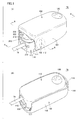
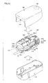
- biological information measurement device 78 is constituted of upper and lower holding members 200 and 210, a main body portion 500 constituted of electronic components which will be described later, and an upper cover 100 and a lower cover 110 (hereinafter also simply referred to as cover 100, 110) covering main body portion 500.
- cover 100, 110 an upper cover 100 and a lower cover 110 covering main body portion 500.
- Upper cover 100 is fixed to upper holding member 200 and integrally operates in cooperation with movement of holding member 200.
- Lower cover 110 is fixed to lower holding member 210 and integrally operates in cooperation with movement of holding member 210.
- Upper cover 100 is formed such that its front surface portion and left and right side surface portions extend from an upper surface portion in a vertical direction, and lower cover 110 is accommodated in a cavity formed by these upper surface portion, the left and right side surface portions and the front surface portion. Namely, an inner surface of the front surface portion of upper cover 100 faces the front surface portion of lower cover 110, and inner surfaces of the left and side surface portions of upper cover 100 face left and right side surface portions of lower cover 110, respectively.
- the inner surface of the front surface portion of upper cover 100 slides with respect to the front surface portion of lower cover 110, and the inner surfaces of the left and right side surface portions of upper cover 100 slide with respect to the left and right side surface portions of lower cover 110, respectively.
- cushion materials 300 and 310 are provided in holding members 200 and 210 respectively, between upper cover 100 and lower cover 110.
- a fingertip is inserted between cushion material 300 provided in holding member 200 and cushion material 310 provided in holding member 210, and a fingertip insertion portion 320, which is a space in a substantially columnar shape where the fingertip is to be disposed, is formed.
- fingertip insertion portion 320 has a fingertip insertion port 350, which is a substantially circular region in which the fingertip starts to be inserted, at an end portion of fingertip insertion portion 320.
- a state that fingertip insertion portion 320 is opened means that fingertip insertion port 350 is opened from an initial state for insertion of the fingertip
- a state that fingertip insertion portion 320 is closed means that fingertip insertion port 350 is in the initial state and also encompasses a state that fingertip insertion port 350 is opened from the initial state with the fingertip being held therein.
- lower cover 110 is formed to cover holding member 210 or the like constituting main body portion 500 and upper cover 100 is formed to overlap with the outer surface of lower cover 110.
- upper cover 100 is provided with a tip end portion 109 on the side opposite to fingertip insertion port 350 of fingertip insertion portion 320, that is, on an extension of the fingertip inserted in fingertip insertion portion 320.
- lower cover 110 is also similarly provided with a tip end portion 119 on the side opposite to fingertip insertion port 350 of fingertip insertion portion 320, that is, on the extension of the fingertip inserted in fingertip insertion portion 320.
- Tip end portion 109 of upper cover 100 is formed to partially overlap with an outer surface of tip end portion 119 of lower cover 110.
- a length in a direction of opening and closing of fingertip insertion port 350, of overlap of the outer surfaces of tip end portions 109 and 119 of upper cover 100 and lower cover 110 is longer than a distance of movement of holding members 200 and 210 in the direction of opening and closing of fingertip insertion port 350 by means of guide mechanism 223.
- tip end portion 109 of upper cover 100 and tip end portion 119 of lower cover 110 are displaced by means of guide mechanism 223, so that insertion of a finger in fingertip insertion portion 320 is facilitated. Even in maximum displacement of the tip end portions, the tip end portions maintain the overlapping state, and thus no gap is formed at the tip end portion of biological information measurement device 78.
- upper cover 100 is provided with side portions 107 and 108 provided on respective sides of fingertip insertion portion 320.
- Lower cover 110 is also similarly provided with side portions 116 and 117 provided on respective sides of fingertip insertion portion 320.
- side portions 107 and 108 of upper cover 100 partially overlap with side portions 116 and 117 of lower cover 110, respectively, and a second restriction member which will be described later maintains such a state that side portions 107 and 108 of upper cover 100 partially overlap with side portions 116 and 117 of lower cover 110 respectively even when fingertip insertion port 350 of fingertip insertion portion 320 is opened as widely as possible.
- a local recess 105 is provided in a surface of upper cover 100 on the tip end portion side.
- a local recess 106 is provided in a surface of lower cover 110 on the tip end portion side.
- Recesses 105 and 106 provided in upper cover 100 and lower cover 110 respectively form grip portions for facilitating pinching of biological information measurement device 78.
- fingertip insertion portion 320 can readily be opened.
- the grip portion is desirably in such a shape as fitting to the fingertip and less likely to cause slipping.
- a design as a recess has been described, however, the design is not particularly limited thereto. For example, a projection may be provided or another shape may be employed.
- a pair of upper and lower holding members 200 and 210 capable of relative displacement in a direction of opening and closing of fingertip insertion port 350, that are opposed to the fingertip inserted through fingertip insertion port 350 and disposed in fingertip insertion portion 320, is shown.
- the holding member is shown with hatching.
- a pair of left and right brackets 220 and 224 provided perpendicularly toward upper holding member 200 are provided, in an end portion of lower holding member 210 in the rear in the direction of insertion of the fingertip (in the direction from left to right in Fig. 2 ).
- a spring 250 is provided as biasing means for biasing upper holding member 200 and lower holding member 210 in a closing direction.
- spring 250 is constituted of an engagement spring portion 252 of which end portion is engaged with upper holding member 200 on a side surface side of holding members 200 and 210, a loop spring portion 254 forming a loop, and a fixed spring portion 256 extending from loop spring portion 254 and fixed to lower holding member 210, and the spring biases holding member 200 engaged with engagement spring portion 252 toward lower holding member 210 fixed to fixed spring portion 256.
- Fig. 3 shows a similar structure of spring 250 on the other side surface side.
- the spring is constituted of an engagement spring portion 266 of which end portion is engaged with upper holding member 200, a loop spring portion 262, and a fixed spring portion 264, and the spring biases holding member 200 engaged with engagement spring portion 266 toward lower holding member 210 fixed to fixed spring portion 264.
- the spring portions provided on the side surface sides of holding members 200 and 210 are integrally formed as a wire spring, by means of coupling portion 260.
- a first restriction member for restricting relative displacement of holding members 200 and 210 in a direction intersecting the direction of opening and closing of fingertip insertion port 350 (front-rear and left-right directions, with a direction in which upper holding member 200 is located being assumed as an upward direction and a direction in which fingertip insertion port 350 of fingertip insertion portion 320 is located being assumed as a rear side) is provided.
- Guide mechanism 223 for guiding movement of holding members 200 and 210 in the direction of opening and closing of fingertip insertion port 350 is provided as the first restriction member between holding members 200 and 210.
- Guide mechanism 223 is constituted of a guide groove 221 slidably engaged with a side surface of bracket 220 of lower holding member 210 and a shaft portion 222 in a short columnar shape provided as a projection on the side surface of upper holding member 200. This shaft portion 222 is fitted to guide groove 221 in a slidable and reciprocating manner, to thereby implement guide mechanism 223.
- Fig. 3 shows an example where a guide mechanism 227 is provided on the opposite side, for the purpose the same as that of guide mechanism 223.
- guide mechanism 227 is constituted of a guide groove 225 slidably engaged with a side surface of bracket 224 of lower holding member 210 and a shaft portion 226 in a short columnar shape provided as a projection on the side surface of upper holding member 200.
- This shaft portion 226 is fitted to guide groove 225 in a slidable and reciprocating manner, to thereby implement guide mechanism 227.
- guide mechanisms 223 and 227 guide movement of holding members 200 and 210 in the direction of opening and closing of fingertip insertion port 350, an operation at the time when holding members 200 and 210 are opened and closed can smoothly be performed.
- fitting of a finger when fingertip M is inserted in fingertip insertion portion 320 can be achieved.
- the opening and closing operation can be stabilized with a simplified structure.
- a region 230 for placing the light emission portion is provided in a central portion of holding member 200 and a region 232 for placing the light reception portion is provided in a central portion of lower holding member 210.
- a structure that the regions for placing the light emission portion and the light reception portion are arranged in upper and lower holding members 200 and 210 respectively is described, however, such arrangement may be interchanged.
- the light emission portion and the light reception portion are separately arranged in the upper and lower holding members, respectively.
- the light emission portion and the light reception portion may be arranged in an identical holding member.
- main body portion 500 is constituted of upper holding member 200, lower holding member 210, spring 250, and the electronic components arranged in the holding members, main body portion 500 alone having such a structure can hold a finger and measure biological information.
- cushion material 300 formed of rubber, a soft resin, a foam, or the like is bonded to upper holding member 200 with an adhesive.
- cushion material 310 is also bonded to lower holding member 210 with an adhesive.
- Cushion materials 300 and 310 are formed opposed to each other, and holding members 200 and 210 and cushion materials 300 and 310 form fingertip insertion port 350 which is a substantially circular space in which a fingertip is to be inserted.
- Fig. 4 shows with a dotted line, that light emission substrate 400 is placed in region 230 in holding member 200 and light reception substrate 404 is placed in region 232 in lower holding member 210.
- a light reception element provided in light reception substrate 404 receives light emitted from a light emission element provided in light emission substrate 400 and transmitted through fingertip M held by holding members 200 and 210.
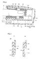
- Fig. 5 is a side cross-sectional view of covers 100 and 110 and holding members 200 and 210 while fingertip insertion port 350 is closed.
- cushion materials 300 and 310 are formed opposed to each other and they form fingertip insertion portion 320 which is a space in a substantially columnar shape.
- a finger is inserted in fingertip insertion portion 320 which is the space, a dorsal side of the finger abuts cushion material 300, and a palm side of the finger abuts cushion material 310.
- cushion materials 300 and 310 are provided in holding members 200 and 210 respectively has been described, however, only one of them may be provided or neither of them may be provided.
- a folded portion 231 is provided in holding member 200 Specifically, on the end portion side in the rear relative to the region where light emission substrate 400 and light reception substrate 404 are placed, in the direction of insertion of the fingertip (the direction from left to right in Fig. 2 ), folded portion 231 provided perpendicularly to extend in the direction of opening and closing of fingertip insertion port 350 is provided. Cushion material 300 is also folded. Then, folded portion 231 forms wall portion 330.
- fingertip M inserted in fingertip insertion portion 320 can be inserted only as far as wall portion 330. Namely, insertion of fingertip M can be restricted and a biological signal can be obtained at an appropriate position. If wall portion 330 is absent, the fingertip may be caught in a gap formed at the tip end portion of the holding member or in a gap formed inside the tip end portion of upper cover 100 and lower cover 110 by insertion of fingertip M in the rear in the absence of wall portion 330. Presence of wall portion 330, however, can prevent the fingertip from being caught.
- a wall portion may be formed as a member separate from the holding member.
- guide mechanism 223 movement of guide mechanism 223 is shown with a dotted line.
- shaft portion 222 in a short columnar shape provided as a projection is located at a restriction end 228 (lower end) on the closing direction side, which is an end portion of guide groove 221 of bracket 220 in a direction opposite to the opening direction in which fingertip insertion portion 320 is opened.
- Fig. 6 is a side cross-sectional view of holding members 200 and 210 in such a state that fingertip insertion portion 320 is closed while fingertip M is inserted in fingertip insertion portion 320.
- fingertip M is inserted in fingertip insertion portion 320
- holding member 200 is lifted in the direction of opening of fingertip insertion port 350 by means of guide mechanism 223 depending on a diameter of a finger, so that biological information can be measured in a fingertip fitted state.
- shaft portion 222 in a short columnar shape provided as a projection is located at a restriction end 229 (upper end) on the opening direction side, which is an end portion of guide groove 221 of bracket 220 in the opening direction in which fingertip insertion portion 320 is opened.
- tip end portion 109 provided in upper cover 100 and tip end portion 119 provided in lower cover 110 are restricted by guide mechanism 223 at a position where the covers partially overlap with each other.
- a length of overlap in the direction of opening and closing of fingertip insertion port 350, of the outer surfaces of tip end portions 109 and 119 of upper cover 100 and lower cover 110 is longer than a distance of movement in the direction of opening and closing of fingertip insertion port 350, of holding members 200 and 210, by means of guide mechanism 223.
- tip end portion 109 of upper cover 100 is formed to partially overlap with the outer surface of tip end portion 119 of lower cover 110 even when fingertip insertion portion 320 is closed. Even when fingertip insertion portion 320 is opened, no gap is formed between upper cover 100 and lower cover 110 in tip end portion 109 of upper cover 100. Namely, when fingertip insertion portion 320 is opened and closed, no gap is formed in the tip end portion.
- biological information measurement device 78 is further provided with a second restriction member for restricting relative displacement of holding members 200 and 210 in the direction of opening and closing of fingertip insertion port 350, on fingertip insertion port 350 side of fingertip insertion portion 320, in addition to guide mechanism 223.
- the second restriction member is provided between side portions 107, 108 of upper cover 100 coupled to holding member 200 and side portions 116, 117 of lower cover 110 coupled to holding member 210.
- a guide mechanism 113 for guiding movement of holding members 200 and 210 in the direction of opening and closing of fingertip insertion port 350 is provided between upper cover 100 and lower cover 110 (between side portion 107 and side portion 116 (a right side portion in Fig. 4 )).
- Guide mechanism 113 is constituted of a shaft portion 102 in a substantially short semicolumnar shape provided as a projection on the side surface of side portion 107 of upper cover 100 on lower cover 110 side, and a guide groove 112 provided as a recess in the side surface of side portion 116 of lower cover 110 on upper cover 100 side and slidably engaged with shaft portion 102.
- Shaft portion 102 is fitted to guide groove 112 in a slidable and reciprocating manner, to thereby implement guide mechanism 113.
- a guide mechanism 115 for guiding movement of holding members 200 and 210 in the direction of opening and closing of fingertip insertion port 350 is provided between upper cover 100 and lower cover 110 (between side portion 108 and side portion 117 (a left side portion in Fig. 4 )).
- Guide mechanism 115 is constituted of a shaft portion 104 in a substantially short columnar shape provided as a projection on the side surface of side portion 108 of upper cover 100 on lower cover 110 side, and a guide groove 114 provided as a recess in the side surface of side portion 117 of lower cover 110 on upper cover 100 side and slidably engaged with shaft portion 104.
- Shaft portion 104 is fitted to guide groove 114 in a slidable and reciprocating manner, to thereby implement guide mechanism 115.
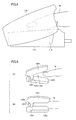
- Fig. 7(A) shows guide mechanism 113 in region 111 in Fig. 1 while fingertip insertion portion 320 is closed.
- shaft portion 102 is located at a restriction end (lower end) in the closing direction side, which is an end portion of guide groove 112 provided as a recess in the direction opposite to the opening direction in which fingertip insertion portion 320 is opened.
- Fig. 7(B) shows guide mechanism 113 in region 111 in Fig. 1 while fingertip insertion portion 320 is opened.
- shaft portion 102 is located at a restriction end (upper end) in the opening direction side, which is an end portion of guide groove 112 provided as a recess in the opening direction in which fingertip insertion portion 320 is opened.
- fingertip insertion port 350 of fingertip insertion portion 320 alone is opened.
- this fingertip clip is structured such that holding members 1201 and 1202 for holding fingertip M are engaged with each other by using engagement portions 1203 and 1204 provided in the front in the direction of insertion of the fingertip and holding members 1201 and 1202 are biased in the closing direction by a not-shown closing spring.
- Fig. 9(A) fingertip M is inserted, with a side closer to hand being opened.
- Fig. 9(B) shows a state that fingertip M is inserted as far as the rear and holding members 1201 and 1202 are closed.
- a side portion 1302 is present where another finger or the like other than fingertip M where measurement should be conducted is readily introduced from the side. Namely, as there is a gap in side portion 1302 of the fingertip clip, for example, another finger or the like may inadvertently be caught in the gap when the fingertip clip is closed.
- a tip end portion 1304 where another finger or the like other than fingertip M where measurement should be conducted is readily introduced is present on an extension of holding members 1201 and 1202 between which the fingertip is inserted.
- Presence of a gap may readily cause introduction of external light through side portion 1302, tip end portion 1304 or the like, in a measurement state where holding members 1201 and 1202 are closed, and the light may reach a light reception element. Accordingly, light shielding performance is low and accuracy in biological information measurement is low.
- biological information measurement device 78 when fingertip M is inserted in fingertip insertion portion 320, that is, when fingertip insertion portion 320 is closed, no gap is formed in side portions 107 and 108 of biological information measurement device 78 owing to guide mechanisms 113 and 115. Therefore, for example, such a problem that another finger or the like is inadvertently caught when fingertip insertion portion 320 is closed can be avoided and the biological information measurement device can safely be used.
- fingertip insertion portion 320 when fingertip insertion portion 320 is closed, side portions 107 and 108 of upper cover 100 are formed to cover the side portions of lower cover 110. Therefore, since no gap is formed in the side portion of biological information measurement device 78 when fingertip insertion portion 320 is closed, light shielding performance while fingertip M is inserted in fingertip insertion portion 320 can be enhanced and accuracy in biological information measurement can be improved.
- tip end portion 109 of upper cover 100 is formed to partially overlap with lower cover 110 and no gap is formed as described above. Therefore, for example, such a problem that another finger or the like is caught in the gap when the fingertip insertion portion is opened can be avoided and the biological information measurement device can safely be used.
- fingertip insertion portion 320 when fingertip insertion portion 320 is closed, upper cover 100 is formed to cover the tip end portion of lower cover 110. Therefore, as no gap is formed at the tip end portion of biological information measurement device 78 when fingertip insertion portion 320 is closed, light shielding performance while fingertip M is inserted in fingertip insertion portion 320 can be enhanced and accuracy in biological information measurement can be improved.
- a holding mechanism in the present device is constituted of guide grooves 221 and 225 included in the holding members and spring 250, however, this holding mechanism is covered with upper cover 100 and lower cover 110 such that it is not exposed to the outside.
- a holding mechanism portion serves as a fulcrum when it is movable, large force is applied thereto.
- a spring or the like is provided, such a problem as catching is more likely.
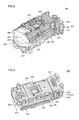
- the electronic component constituting main body portion 500 includes a main body substrate 406 on which a chip for controlling the biological information measurement device and performing signal processing is mounted, light emission substrate 400 on which a light emission element is mounted, light reception substrate 404 on which a light reception element is mounted, cables 402 and 403 connecting light emission substrate 400 and light reception substrate 404 to the main body substrate, and a connector 408 for connection with cable 79 provided in main body substrate 406.
- Fig. 11 is a structure diagram of main body portion 500 of biological information measurement device 78 incorporating the electronic components illustrated in Fig. 10 .
- light reception substrate 404 described above is placed in region 232 for placing a light reception portion, that is provided in the central portion of lower holding member 210 described in connection with Fig. 3 .
- a substrate holder 244 for fixing main body substrate 406 is attached thereto.
- main body substrate 406 is placed on substrate holder 244 and main body substrate 406 is fixed by pawls 246 and 248 provided on respective opposing sides of substrate holder 244.
- FIG. 11(B) a case where light emission substrate 400 described above is placed in region 230 for placing the light emission portion, that is provided in the central portion of upper holding member 200, is shown.
- main body portion 500 of biological information measurement device 78 is completed.
- Fig. 12 is a diagram showing that upper cover 100, main body portion 500 and lower cover 110 of the biological information measurement device are assembled.
- main body portion 500 is covered as shown in Fig. 1 , by assembling upper cover 100 and lower cover 110. Namely, main body portion 500 is separate from upper cover 100 and lower cover 110 for covering main body portion 500. As described above, upper cover 100 and lower cover 110 are assembled. By assembling upper cover 100 and lower cover 110 to cover entire main body portion 500, even when the substrate and the line of main body portion 500 are arranged on the side surface of the main body in the inside, they cannot externally be seen.
- the substrate and the line of main body portion 500 are not exposed, so that such a problem that the user inadvertently touches the electronic component or the finger is caught in the gap can be avoided, safety is ensured, and failure is less likely.
- guide mechanisms 223 and 227 that are movable portions in main body portion 500, are entirely covered by assembling upper cover 100 and lower cover 110, to thereby eliminate a gap and make an internal structure invisible. Thus, safe use can be achieved.
- main body portion 500 can readily be taken out and an operation for maintenance or the like is easy.
- main body portion 500 by arranging the substrate and the line on the outer surface of main body portion 500, a space can effectively be made use of and an operation for maintenance or the like of an electronic circuit portion is facilitated.
- main body portion 500 is provided separately from upper cover 100 and lower cover 110, a degree of freedom in designing entire biological information measurement device 78 can be improved, without restriction being imposed by the structure of main body portion 500. Namely, as a measurement function is completed by the measurement unit alone, a shape of a covering member can freely be designed, without restriction being imposed by design for a measurement function.
- Biological information measurement device 78 in the present example is structured to incorporate not only the light reception substrate and the light emission substrate but also a chip for controlling the biological information measurement device and performing signal processing, however, it is also possible that only the light reception substrate and the light emission substrate are provided and another device may control the biological information measurement device and perform signal processing.
- upper cover 100 may cover the holding member and the like constituting main body portion 500 and lower cover 110 may be formed to lie over the outer surface of upper cover 100.
- biological information measurement device 78 is used in a game device.
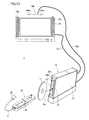
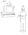
- a video game system 1 representing one type of an information processing system according to the embodiment of the present invention will be described with reference to Fig. 13 .
- video game system 1 includes a game device 12, a controller 22, and biological information measurement device 78.
- Game device 12 is a stationary game device.
- Controller 22 represents one type of peripheral equipment for game device 12, that serves as a user's or player's input device or operation device.
- Controller 22 can connect biological information measurement device 78 for measuring human biological information as expansion equipment for game device 12.
- Game device 12 is designed to be able to communicate with controller 22.
- game device 12 and controller 22 are connected to each other through wireless communication.
- wireless communication is implemented under Bluetooth ® specifications, however, it may be implemented under other specifications such as infrared or wireless LAN. Alternatively, wire connection may be adopted.
- Game device 12 includes a housing 14 in a substantially parallelepiped shape, and a disc slot 16 is provided in a front surface of housing 14.
- An optical disc 18 typically representative of a storage medium for storing a game program or the like is inserted in disc slot 16 and attached to a disc drive 54 (see Fig. 14 ) within housing 14.
- An LED and a light guide plate are arranged around disc slot 16, and the LED can illuminate in response to various processes.
- a power button 20a and a reset button 20b are provided in an upper portion thereof and an eject button 20c is provided in a lower portion thereof.
- a connector cover 28 for an external memory card is provided between reset button 20b and eject button 20c, in the vicinity of disc slot 16.
- An external memory card connector 62 (see Fig. 14 ) is provided inside connector cover 28 for external memory card, in which a not-shown external memory card (hereinafter simply also referred to as a "memory card”) is inserted.
- the memory card is used for temporarily storing a game program or the like that is read from optical disc 18 and loaded, or it is used for storing (saving) game data of the game played with this video game system 1 (data of a game result or data while playing the game)
- the game data above may be stored in an internal memory such as a flash memory 44 (see Fig. 14 ) provided inside game device 12, instead of the memory card.
- the memory card may be used as a back-up memory for the internal memory.
- the game program or the like may be supplied (downloaded) to game device 12 from a server or the like connected to the network through a wire or wireless communication channel. The game program or the like thus downloaded is stored in flash memory 44 (see Fig. 14 ) or a memory card provided in game device 12.
- a general-purpose SD (Secured Digital) card may be employed as the memory card, however, other general-purpose memory cards such as a memory stick or a multimedia card (trademark) may also be employed.
- SD Secured Digital
- An AV cable connector 58 (see Fig. 14 ) is provided on a rear surface of housing 14 of game device 12.
- An AV cable 32a is connected to AV connector 58, and a monitor 34 (a display portion) and a speaker 34a (an audio output portion) are connected to game device 12 through this AV cable 32a.
- Monitor 34 and speaker 34a are typically implemented by a color television.
- AV cable 32a inputs a video signal from game device 12 to a video input terminal of the color television and inputs an audio signal to an audio input terminal. Therefore, for example, a game image of a three-dimensional (3D) video game is displayed on a screen of color television (monitor) 34 and stereophonic game sound such as game music or sound effect is output from left and right speakers 34a.
- 3D three-dimensional
- a marker portion 34b having two infrared LEDs (markers) 340m and 340n is provided around monitor 34 (in the example shown in Fig. 13 , on the top of monitor 34).
- Marker portion 34b is connected to game device 12 through a power cable 32b. Therefore, marker portion 34b is supplied with power from game device 12.
- markers 340m and 340n emit light and output infrared rays from the front of monitor 34.
- Game device 12 is supplied with power by a general AC adapter (not shown).
- the AC adapter is inserted in an ordinary wall outlet at home and power supply for home (commercial power supply) is converted to a low DC voltage signal suitable for driving game device 12.
- a battery may be employed as the power supply.
- game device 12 When the user plays a game (or another application, without limited to the game) with this video game system 1, the user initially turns on power of game device 12, selects appropriate optical disc 18 recording a program of a video game (or another application the user desires to play), and loads optical disc 18 to disc drive 54 of game device 12. Then, game device 12 starts execution of the video game or another application based on the program recorded on that optical disc 18. Alternatively, game device 12 may start execution of the video game or another application based on a program downloaded in advance from the server and stored in flash memory 44 (see Fig. 14 ) or the like.
- the user operates controller 22 to provide an input to game device 12. For example, by operating any input portion 26, the user starts the game or another application. Further, by moving controller 22 itself other than operating input portion 26, the user can move a motion picture object (a user object) in a different direction or change a point of view of the user (a camera position) in a 3D game world.
- a motion picture object a user object
- a point of view of the user a camera position
- each component within housing 14 is mounted on a printed circuit board.
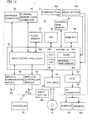
- game device 12 is provided with a CPU 40.
- CPU 40 functions as a game processor.
- a system LSI 42 is connected to CPU 40.
- An external main memory 46, a ROM/RTC 48, disc drive 54, and an AV_IC 56 are connected to this system LSI 42.
- External main memory 46 stores a program of various applications or various types of data, and it is used as a work area or a buffer area of CPU 40.
- ROM/RTC 48 is what is called a boot ROM, and a program for starting up game device 12 is incorporated therein and ROM/RTC 48 is provided with a time counting circuit for counting time. Namely, CPU 40 obtains current time and day (year, month, day, and time) by referring to ROM/RTC 48.
- Disc drive 54 reads program data, texture data or the like from optical disc 18, and writes such data in an internal main memory 42e or external main memory 46 which will be described later under the control of CPU 40.
- System LSI 42 includes an input/output processor 42a, a GPU (Graphics Processor Unit) 42b, a DSP (Digital Signal Processor) 42c, a VRAM 42d, and internal main memory 42e, and these components are connected to one another through an internal bus.
- a GPU Graphics Processor Unit
- DSP Digital Signal Processor
- I/O processor 42a transmits and receives data or downloads data. Transmission and reception and downloading of data will be described later in detail.
- GPU 42b forms a part of rendering means. Receiving a graphics command (an image creation command) from CPU 40, GPU 42b generates game image data in accordance with the command. It is noted that CPU 40 provides an image generation program necessary for generating game image data to GPU 42b, in addition to the graphics command.
- VRAM 42d is connected to GPU 42b.
- GPU 42b obtains data necessary for GPU 42b to execute the image creation command (image data: data such as polygon data or texture data) by accessing VRAM 42d.
- image data data such as polygon data or texture data
- CPU 40 writes image data necessary for rendering in VRAM 42d, by utilizing GPU 42b.
- GPU 42b accesses VRAM 42d and creates the game image data for rendering.
- GPU 42b generates game image data.
- GPU 42b when some kind of application other than the game application is executed, GPU 42b generates image data for that application.
- DSP 42c functions as an audio processor and generates audio data corresponding to sound, voice or music to be output from speaker 34a, by using sound data or a sound waveform (tone) data stored in internal main memory 42e or external main memory 46.
- the game image data and the audio data generated as described above are read by AV_IC 56 and output to monitor 34 and speaker 34a through AV cable connector 58. Therefore, a game picture is displayed on monitor 34 and sound (music) necessary for the game is output from speaker 34a.
- flash memory 44 a wireless communication module 50 and a wireless controller module 52 as well as an expansion connector 60 and external memory card connector 62 are connected to input/output processor 42a.
- an antenna 50a is connected to wireless communication module 50 and an antenna 52a is connected to wireless controller module 52.
- Input/output processor 42a can communicate with another game device or various servers connected to the network through wireless communication module 50.
- input/output processor 42a receives input data transmitted from controller 22 through antenna 52a and wireless controller module 52, and causes internal main memory 42e or external main memory 46 to store (temporarily store) the input data in a buffer area thereof After the input data is used in game processing by CPU 40, it is erased from the buffer area.
- wireless controller module 52 communicates with controller 22 under Bluetooth ® specifications.
- expansion connector 60 and external memory card connector 62 are connected to input/output processor 42a.
- Expansion connector 60 is a connector for an interface such as a USB or an SCSI, and a medium such as an external storage medium or peripheral equipment such as another controller can be connected.
- a wired LAN adapter may be connected to expansion connector 60 and wired LAN can be utilized instead of wireless communication module 50.
- An external storage medium such as a memory card can be connected to external memory card connector 62. Therefore, for example, input/output processor 42a can access the external storage medium to store data therein or to read data therefrom, through expansion connector 60 or external memory card connector 62.
- game device 12 (housing 14) is provided with power button 20a, reset button 20b and eject button 20c.
- Power button 20a is connected to system LSI 42.
- system LSI 42 supplies power to each component in game device 12 through a not-shown AC adapter and sets a mode in a normally powered state (referred to as a normal mode).
- power button 20a when power button 20a is turned off, system LSI 42 supplies power only to some components in game device 12 and sets a mode in which power consumption is minimized (hereinafter also referred to as a "stand-by mode").
- system LSI 42 indicates stop of power supply to components other than input/output processor 42a, flash memory 44, external main memory 46, ROMIRTC 48, wireless communication module 50, and wireless controller module 52. Therefore, the stand-by mode refers to a mode in which CPU 40 does not execute an application.
- a fan for expelling heat of an IC such as CPU 40 or system LSI 42 is provided in housing 14 of game device 12. In the stand-by mode, this fan is also stopped. If the user does not wish to use the stand-by mode, setting for not using the stand-by mode may be made so that power supply to all circuit components is completely stopped as power button 20a is turned off.
- switching between the normal mode and the stand-by mode may also be made remotely by switching on and off a power switch 26h of controller 22.
- a remote operation is not performed, such setting that power is not supplied to wireless controller module 52 in the stand-by mode may be made.
- Reset button 20b is also connected to system LSI 42. When reset button 20b is pressed, system LSI 42 re-starts a start-up program of game device 12. Eject button 20c is connected to disc drive 54. When eject button 20c is pressed, optical disc 18 is ejected from disc drive 54.
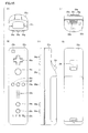
- Figs. 15(A) to 15(E) show exemplary appearance of controller 22.
- Fig. 15(A) shows a tip end surface of controller 22
- Fig. 15(B) shows an upper surface of controller 22
- Fig. 15(C) shows a right side surface of controller 22
- Fig. 15(D) shows a lower surface of controller 22
- Fig. 15(E) shows a rear end surface of controller 22.
- controller 22 has a housing 22a formed, for example, by plastic molding.
- Housing 22a is in a substantially parallelepiped shape and has such a size as being held by the user with one hand.
- Housing 22a (controller 22) is provided with input means (a plurality of buttons or switches) 26.
- input means a plurality of buttons or switches
- a cross key 26a, a 1 button 26b, a 2 button 26c, an A button 26d, a - button 26e, a HOME button 26f, a + button 26g, and power switch 26h are provided on the upper surface of housing 22a.
- an inclined surface is formed in the lower surface of housing 22a, where a B trigger switch 26i is provided.
- Cross key 26a is a four-directional push switch, and includes operation portions pointing to four directions shown with arrows, that is, front (or up), rear (or down), right, and left. As the user operates any one of these operation portions, a direction of movement of a character or an object (a user character or a user object) operable by the user can be indicated or a direction of movement of a cursor can be indicated.
- Each of 1 button 26b and 2 button 26c is a push-button switch.
- these buttons are used for a game operation such as adjustment of a position of a viewpoint or a direction of viewpoint, that is, a position or a field angle of a virtual camera, for example, in displaying a three-dimensional game image.
- 1 button 26b and 2 button 26c may be used for an operation the same as that with A button 26d and B trigger switch 26i, respectively, or for an auxiliary operation.
- a button 26d is a push-button switch, and it is used for causing the user character or the user object to perform an operation other than indication of a direction, that is, any action including hitting (punching), throwing, catching (grasping), riding, jumping, or the like.
- jumping, punching, actuating a weapon, or the like can be indicated.
- RPG role-playing game
- simulation RPG acquiring of an item, selection and determination of a weapon or a command, or the like can be indicated.
- Each of - button 26e, HOME button 26f, + button 26g, and power switch 26h is also a push-button switch.
- - button 26e is used for selecting a game mode.
- HOME button 26f is used for displaying a game menu (a menu screen).
- + button 26g is used for starting (resuming) a game or causing the game to pause.
- Power switch 26h is used for turning on/off power of game device 12 by remote operation.
- controller 22 is configured such that it is turned on by operating any input portion 26 of controller 22 and it is automatically turned off in the absence of an operation for a prescribed period (for example, 30 seconds) or longer.
- B trigger switch 26i is also a push-button switch, and it is mainly used for providing an input simulating a trigger such as shooting a gun or for designating a position selected by controller 22. In addition, by keeping pressing B trigger switch 26i, an operation of the user object or a parameter can also be maintained in a prescribed state. In addition, in a prescribed case, B trigger switch 26i functions similarly to a normal B button, and it is used for canceling an action determined by using A button 26d.
- an external expansion connector 22b is provided in the rear end surface of housing 22a, and as shown in Fig. 15(B) , an indicator 22c is provided on the upper surface of housing 22a, toward the side of the rear end surface.
- External expansion connector 22b is used for connection to biological information measurement device 78 representing expansion equipment which will be described later.
- Indicator 22c is constituted, for example, of four LEDs. Illumination of any one of these four LEDs can indicate identification information (a controller number) of controller 22 corresponding to the illuminating LED or indicate a state of charge of controller 22 based on the number of illuminating LEDs.
- controller 22 has an image pick-up information operation unit 80 (see Fig. 16 ), and a light incident port 22d of image pick-up information operation unit 80 is provided at the tip end surface of housing 22a as shown in Fig. 15(A) .
- controller 22 has a speaker 86 (see Fig. 16 ). As shown in Fig. 15(B) , speaker 86 is provided inside housing 22a, in correspondence with a sound emission hole 22e provided in the upper surface of housing 22a, between 1 button 26b and HOME button 26f.
- controller 22 and the shape, the number, the position, and the like of input portions 26 shown in Figs. 15(A) to 15(E) are merely by way of example, and even variation as appropriate thereof is encompassed in the essence of the present invention.
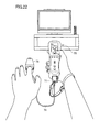
- controller 22 is used in such a state that it is connected to biological information measurement device 78 representing the expansion equipment shown in Fig. 13 .
- biological information measurement device 78 representing the expansion equipment shown in Fig. 13 .
- external expansion connector 22b provided in the rear end surface of housing 22a and a connector of biological information measurement device 78 are connected to each other.
- controller 22 An electric configuration of controller 22 will mainly be described with reference to Fig. 16 .
- controller 22 includes a processor 70, to which external expansion connector 22b, input portion 26, a memory 72, an acceleration sensor 74, a wireless module 76, image pick-up information operation unit 80, an LED 82 (indicator 22c), a vibrator 84, speaker 86, and a power supply circuit 88 are connected through an internal bus (not shown).
- an antenna 71 is connected to wireless module 76.
- Wireless module 76 and processor 70 implement a communication unit 75 for communicating data with game device 12. It is noted that external expansion connector 22b is connected to a connector 77 of biological information measurement device 78.
- Biological information measurement device 78 is connected to processor 70 through a cable 79, connector 77, and external expansion connector 22b, so that biological information data from biological information measurement device 78 is input to processor 70.
- biological information measurement device 78 is connected to controller 22 through cable 79, it is not necessary to consider radio wave interference with wireless module 76 of controller 22, and hence data can be output to controller 22 in a stable manner.
- Processor 70 is responsible for overall control of controller 22, and it transmits (inputs) as input data, information input from input portion 26, acceleration sensor 74, image pick-up information operation unit 80, and external expansion connector 22b (input information) to game device 12 through wireless module 76 and antenna 71.
- processor 70 uses memory 72 as a work area or a buffer area.
- Input information which is an operation signal (operation data) from input portion 26 (26a to 26i) described above is input to processor 70, which once causes memory 72 to store the operation data.
- acceleration sensor 74 detects each acceleration in three axes of a vertical direction (direction of y-axis), a horizontal direction (direction of x-axis) and a front-rear direction (direction of z-axis) of controller 22.
- Acceleration sensor 74 is typically a capacitance-type acceleration sensor, however, a sensor of another type may be employed.
- acceleration sensor 74 detects acceleration for each of the x-axis, the y-axis and the z-axis (ax, ay, az) every first prescribed time, and inputs the detected acceleration data (acceleration data) to processor 70.
- acceleration sensor 74 detects acceleration in the direction of each axis in a range from -2.0G to 2.0G (G represents acceleration of gravity; to be understood similarly hereinafter).
- Processor 70 detects acceleration data provided from acceleration sensor 74 every second prescribed time, and causes memory 72 to once store the acceleration data.
- biological information measurement device 78 inputs biological information data to processor 70 through external expansion connector 22b.
- Processor 70 causes memory 72 to once store the input biological information data.
- Processor 70 creates input data including at least one of operation data, acceleration data, marker coordinate data which will be described later, and biological information data, and transmits the created input data to game device 12.
- wireless communication from the communication unit to wireless controller module 52 included in housing 14 is carried out in a prescribed cycle, however, processing of the game is generally performed in a unit of 1/60s. Therefore, transmission should be carried out in a cycle shorter than the aforementioned cycle.
- the unit of processing of the game is set to 16.7ms (1/60s), and in the present example, a wireless packet is transmitted from controller 22, for example, in a prescribed cycle (1/200s).
- acceleration sensor 74 is provided on a substrate inside housing 22a, around a position where cross key 26a is arranged.
- controller 22 can be estimated or calculated (determined) as a result of processing by such a computer as the processor of game device 12 (such as CPU 40) or the processor of controller 22 (such as processor 70), based on the acceleration data output from acceleration sensor 74.
- controller 22 if controller 22 is actually in a static state, whether an attitude of controller 22 is inclined with respect to the direction of gravity or how it is inclined can be determined based on the detected acceleration data. Specifically, if a state that an axis detected by the acceleration sensor is in the vertically downward direction is defined as the reference, inclination can be determined only based on whether 1G (acceleration of gravity) is applied or not, and magnitude of inclination can be determined based on magnitude of acceleration of gravity.
- 1G acceleration of gravity
- processor 70 may perform processing for calculating data of an angle of inclination of controller 22 based on outputs from the acceleration sensors, however, processing may be such that approximate inclination can be estimated based on outputs from the acceleration sensors without processing for calculating inclination angle data.
- an inclination, an attitude or a position of controller 22 can be determined.
- acceleration in accordance with movement of the acceleration sensor is detected in addition to a component of acceleration of gravity. Therefore, by eliminating the component of acceleration of gravity with prescribed processing, a direction of movement or the like can be determined. Specifically, when controller 22 having the acceleration sensors is moved in a manner dynamically accelerated by a user's hand, the acceleration data generated by the acceleration sensors is processed so that various movements and/or positions of controller 22 can be calculated.
- the acceleration sensor may incorporate an embedded signal processing device or a dedicated processing device of another type for subjecting an acceleration signal (acceleration data) output from contained acceleration detection means to desired processing prior to output of acceleration data to processor 70.
- an embedded or dedicated processing device may convert sensed acceleration data into a corresponding inclination angle (or other preferred parameters) if the acceleration sensor serves to detect static acceleration (for example, acceleration of gravity).
- Wireless module 76 modulates a carrier wave at a prescribed frequency with input data and emits the resultant weak radio signal from antenna 71, using, for example, the Bluetooth ® technique Namely, input data is modulated by wireless module 76 into a weak radio signal and transmitted from antenna 71 (controller 22). This weak radio signal is received by wireless controller module 52 provided in game device 12 described above. The received weak radio wave is subjected to demodulation and decoding processing, and consequently, game device 12 (CPU 40) can obtain input data from controller 22. Then, CPU 40 performs game processing in accordance with the obtained input data and the program (game program).
- controller 22 is provided with image pick-up information operation unit 80.
- Image pick-up information operation unit 80 is constituted of an infrared filter 80a, a lens 80b, an image pick-up element 80c, and an image processing circuit 80d.
- Infrared filter 80a allows passage of only infrared of light incident from the front of controller 22.
- markers 340m and 340n arranged in the vicinity of (around) a display screen of monitor 34 are infrared LEDs for outputting infrared rays from the front of monitor 34. Therefore, an image of markers 340m and 340n can more accurately be picked up by providing infrared filter 80a.
- Lens 80b collects the infrared rays that have passed through infrared filter 80a and directs the infrared rays toward image pick-up element 80c.
- Image pick-up element 80c is implemented by a solid-state image pick-up element such as a CMOS sensor or a CCD, and it picks up an image of the infrared rays collected by lens 80b. Therefore, image pick-up element 80c picks up an image only of the infrared rays that have passed through infrared filter 80a to generate image data.
- An image picked up by image pick-up element 80c is hereinafter referred to as a picked-up image.
- the image data generated by image pick-up element 80c is processed by image processing circuit 80d.
- Image processing circuit 80d calculates a position of an image pick-up target (markers 340m and 340n) within the picked-up image and outputs each coordinate value indicating the position to processor 70 as the image pick-up data every third prescribed time. Processing in image processing circuit 80d will be described later.
- controller 22 in playing a game using controller 22 in video game system 1, the user holds controller 22 with one hand. Strictly speaking, the user holds controller 22 in such a state that the tip end surface of controller 22 (on the side of port 22d on which light to be picked up by image pick-up information operation unit 80 is incident) is directed toward markers 340m and 340n. As can be seen also from Fig. 13 , however, markers 340m and 340n are arranged in parallel to the horizontal direction of the screen of monitor 34. In such a state, the user performs a game operation by changing a position on the screen indicated by controller 22 or by changing a distance between controller 22 and each marker 340m, 340n.
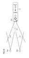
- a viewing angle of markers 340m and 340n and controller 22 will be described with reference to Fig. 18 .
- each of markers 340m and 340n emits infrared rays in a range of a viewing angle ⁇ 1.
- image pick-up element 80c of image pick-up information operation unit 80 can receive incident light in a range of a viewing angle ⁇ 2, with a direction of line of sight of controller 22 being defined as the center.
- viewing angle ⁇ 1 of markers 340m and 340n is set to 34° (half-value angle), while viewing angle ⁇ 2 of image pick-up element 80c is set to 41°. The user holds controller 22 in such a position and an orientation that image pick-up element 80c can receive infrared rays from two markers 340m and 340n.
- controller 22 can sense at least one of markers 340m and 340n.
- the user can perform a game operation by changing the position and the orientation of controller 22 in a range satisfying this condition.
- the picked-up image obtained by image pick-up element 80c includes an image of each marker 340m, 340n, which is a target of image pick-up (target image).
- image processing circuit 80d calculates a coordinate (a marker coordinate) indicating a position of each of markers 340m and 340n on the picked-up image, using the image data of the picked-up image including the target image.
- image processing circuit 80d initially detects this high-luminance portion as a candidate for the target image. Then, image processing circuit 80d determines whether that high-luminance portion is the target image or not, based on a size of the detected high-luminance portion.
- the picked-up image may include not only images 340m' and 340n' of two respective markers 340m and 340n that are the target images but also an image other than the target image due to solar rays passing through a window or light of a fluorescent lamp in a room.
- Processing for determining whether the high-luminance portion is the target image or not is performed in order to distinguish between images 340m' and 340n' of respective markers 340m and 340n that are the target images and an image other than that and to accurately detect the target image. Specifically, in the determination processing, whether the detected high-luminance portion has a size in a predetermined prescribed range or not is determined. When the high-luminance portion has a size in the prescribed range, the high-luminance portion is determined as representing the target image. In contrast, when the high-luminance portion does not have a size in the prescribed range, the high-luminance portion is determined as representing an image other than the target image.
- image processing circuit 80d calculates a position of the high-luminance portion that has been determined as representing the target image, as a result of the determination processing above. Specifically, the position of the center of gravity of the high-luminance portion is calculated.
- the coordinate of the position of the center of gravity is referred to as a marker coordinate.
- the position of the center of gravity can be calculated on an order higher than resolution of image pick-up element 80c.
- the resolution of the image picked up by image pick-up element 80c is assumed as 126 dots ⁇ 96 dots and the position of the center of gravity is calculated on a scale of 1024 dots ⁇ 768 dots.
- the marker coordinate is expressed as an integer value from (0, 0) to (1024, 768).
- the position in the picked-up image is expressed in a coordinate system (an XY coordinate system) in which the upper left of the picked-up image is defined as the origin, a downward direction is defined as the positive direction of the Y-axis, and a right direction is defined as the positive direction of the X-axis.
- Image processing circuit 80d outputs data indicating calculated two marker coordinates.
- the output data of the marker coordinates is included in the input data and transmitted to game device 12 by processor 70, as described above.
- game device 12 When game device 12 (CPU 40) detects the marker coordinate data from the received input data, it can calculate a position indicated by controller 22 on the screen of monitor 34 (an indicated coordinate) and a distance from controller 22 to each of markers 340m and 340n based on this marker coordinate data. Specifically, the position to which controller 22 is directed, that is, the indicated position, is calculated based on the position of an intermediate point between two marker coordinates. In addition, as the distance between the target images in the picked-up image is varied depending on a distance between controller 22 and markers 340m, 340n, game device 12 can obtain the distance between controller 22 and markers 340m, 340n by calculating the distance between the two marker coordinates.
- image processing circuit 80d processes the image data of the picked-up image and the obtained marker coordinate data is transmitted from controller 22 to game device 12
- image data of a photographed image itself may be transmitted from controller 22 to game device 12 and game device 12 may process the image data of the picked-up image to obtain marker coordinate data.
- image processing circuit 80d provided in controller 22 is not necessary.
- a configuration may also be such that image data being processed may be transmitted from controller 22 to game device 12. Specifically, data representing luminance, a position, an area, and the like obtained from the image data may be transmitted from controller 22 to game device 12 and CPU 40 of game device 12 may perform remaining processing to obtain marker coordinate data.
- markers 340m and 340n are employed as image pick-up targets of image pick-up information operation unit 80
- another object may be employed as an image pick-up target.
- one LED module or three or more LED modules may be provided in the vicinity of monitor 34 and infrared rays from such LED module(s) may be employed as the image pick-up target of image pick-up information operation unit 80.
- a display screen itself of monitor 34 or another light emission element such as an interior light
- Various light emission elements can be employed as the image pick-up target of image pick-up information operation unit 80, by operating a position of controller 22 with respect to the display screen of monitor 34 based on relation of arrangement between the image pick-up target and the display screen of monitor 34.
- biological information measurement device 78 includes a control unit 761, a light emission portion 762 and a light reception portion 763, and a signal processing unit 764.
- Control unit 761 and signal processing unit 764 are each implemented by a chip (not shown) provided on main body substrate 406 described in connection with Fig. 10 .
- light emission portion 762 is implemented by light emission substrate 400 on which a light emission element is mounted.
- Light reception portion 763 is implemented by light reception substrate 404 on which a light reception element is mounted.
- Light emission portion 762 and light reception portion 763 represent an exemplary sensor for obtaining user's biological information and they implement a transmission-type digital pulse volume sensor.
- Light emission portion 762 is implemented, for example, by an infrared LED and it emits infrared rays of a prescribed wavelength (for example, 940 nm) toward light reception portion 763.
- light reception portion 763 receives light having a wavelength emitted by light emission portion 762 and it is implemented, for example, by an infrared photoresistor.
- Light emission portion 762 and light reception portion 763 are arranged, with a prescribed gap (cavity) lying therebetween.
- a light reception signal converted to a photoelectric signal by light reception portion 763 is output to signal processing unit 764 and also directly output to control unit 761.
- hemoglobins in blood of a human body tend to absorb infrared rays.
- a part of a user's body for example, a fingertip
- infrared rays emitted from light emission portion 762 are absorbed by hemoglobins in the inserted fingertip and thereafter received by light reception portion 763.
- a diameter of the artery an amount of blood
- pulsation a diameter of the artery (an amount of blood) varies in response to pulsation.
- an amount of blood varies in response to pulsation and an amount of absorbed infrared rays also varies in accordance with the amount of blood.
- the amount of blood flow in the inserted fingertip is large, the amount of light absorption by hemoglobins also increases and hence a quantity of infrared rays received by light reception portion 763 relatively decreases.
- a quantity of infrared rays received by light reception portion 763 is converted into a photoelectric signal (a light reception signal) and thereafter the signal is subjected to prescribed filtering processing in signal processing unit 764, so that pulsation of the human body (hereinafter also referred to as a pulse wave) is detected.
- a pulse wave signal will be described with reference to Fig. 21 .
- a light reception signal received by light reception portion 763 refers to a signal indicating remainder after light absorption by venous blood and tissues in a human body relative to a maximum light reception level value.
- a value of the light reception signal detected by light reception portion 763 decreases.
- a value of the light reception signal detected by light reception portion 763 increases.
- a pulse wave portion where a value detected by light reception portion 763 pulsates is generated as the pulse wave signal.
- such a pulse wave signal that a value of the light reception signal detected by light reception portion 763 decreases when the amount of blood flow in the inserted fingertip decreases and a value detected by light reception portion 763 increases when the amount of blood flow in the inserted fingertip increases can also be generated.
- a pulse wave signal is weak relative to a maximum light reception level as shown in Fig. 21 . Therefore, for distinction between a pulse wave signal and a noise signal generated in light reception portion 763, a value of the light reception signal is also detected in the present embodiment.
- Control unit 761 is implemented, for example, by an MCU (Micro Controller Unit). Control unit 761 controls a quantity of infrared rays emitted from light emission portion 762. In addition, control unit 761 generates pulse wave data (biological information data) by A/D conversion of the pulse wave signal, that has been subjected to filtering processing by signal processing unit 764, in the light reception signal output from light reception portion 763. Moreover, control unit 761 generates light reception level data (biological information data) by A/D conversion of the light reception signal output from light reception portion 763. It is noted that resolution for A/D conversion is set to 10 bits.
- MCU Micro Controller Unit
- a sampling period for generating pulse wave data is set to 1ms (1/1000s).
- a sampling period for generating light reception level data is set to 5ms (1/200s).
- Control unit 761 causes a not-shown buffer to store pulse wave data and light reception level data and outputs the pulse wave data (biological information data) and the light reception level data to controller 22 through cable 79 every prescribed period.
- transmission timing for control unit 761 to output the pulse wave data (biological information data) and the light reception level data to controller 22 is set to 5ms (1/200s).
- sampled, five pieces of pulse wave data having resolution of 10 bits and one piece of light reception level data having resolution of 10 bits are stored in the buffer by the time when timing of transmission of data to controller 22 by control unit 761 comes.
- control unit 761 When the transmission timing comes, control unit 761 outputs the biological information data including the sampled, five pieces of pulse wave data having resolution of 10 bits and one piece of light reception level data having resolution of 10 bits to controller 22.
- processor 70 of communication unit 75 causes memory 72 to once store the biological information data input through external expansion connector 22b, as described above.
- Fig. 22 in playing a game using controller 22 connected to biological information measurement device 78, the user plays the game with his/her one hand holding controller 22 and a finger of the other hand being inserted in biological information measurement device 78.
- the user performs a game operation by changing a position on a screen indicated by controller 22 or by inclining controller 22.
- a game using biological information measurement device 78 will be described with reference to Figs. 23(A) to 23(C) .
- a game in which a player character operates based on a biological signal (pulse wave signal) of the user and on user's movement or attitude (inclination of controller 22) is played.
- remote controller button data, remote controller acceleration data (X, Y, Z), and biological information are transmitted from controller 22 to game device 12.
- a player character PC is requested, in a virtual game world, to fly in a space between a ceiling T and a ground B (for example, in a grotto) that scroll from left to right and serve as obstacles.
- Player character PC is configured such that it can be divided into a first player character PC1 and a second player character arranged above first player character PC1.
- a second player character PC2 can move upward relative to first player character PC1, with ceiling T being the limit.
- second player character PC2 moves upward and downward in accordance with a state of user's respiration. For example, when the user exhales, second player character PC2 moves upward from first player character PC1, and when the user inhales, second player character PC2 moves downward to first player character PC 1.
- a pulse rate of the user is calculated using the pulse wave signal above. When the pulse rate is increasing, it is determined that the user inhales, and when the pulse rate is decreasing, it is determined that the user exhales.
- 100 points are given as initial points, and the point is deducted when second player character PC2 comes in contact with ceiling T, which is an obstacle, or when first player character PC 1 comes in contact with ground B, which is an obstacle.
- player character PC can fly along ground B with its attitude being inclined.
- a flying attitude of player character PC is inclined depending on inclination of controller 22.
- controller 22 For example, when the user directs controller 22 toward monitor 34 and inclines controller 22 by an angle ⁇ 1 to the right, in synchronization with that inclination operation, player character PC is displayed in a manner also inclined by angle ⁇ 1 to the right.
- the user can operate first and second player characters PC 1 and PC2 in the virtual game world using biological information measurement device 78.
- biological information measurement device 78 can be used in all fields.
- the device can be used for measuring a pulse wave in a general household, and the device can naturally be used in the medical field for measuring biological information.
Landscapes
- Health & Medical Sciences (AREA)
- Life Sciences & Earth Sciences (AREA)
- Physics & Mathematics (AREA)
- Biomedical Technology (AREA)
- Medical Informatics (AREA)
- Biophysics (AREA)
- Pathology (AREA)
- Engineering & Computer Science (AREA)
- Veterinary Medicine (AREA)
- Heart & Thoracic Surgery (AREA)
- Public Health (AREA)
- Molecular Biology (AREA)
- Surgery (AREA)
- Animal Behavior & Ethology (AREA)
- General Health & Medical Sciences (AREA)
- Optics & Photonics (AREA)
- Spectroscopy & Molecular Physics (AREA)
- Measurement Of The Respiration, Hearing Ability, Form, And Blood Characteristics Of Living Organisms (AREA)
- Measuring Pulse, Heart Rate, Blood Pressure Or Blood Flow (AREA)
Abstract
Description
- This nonprovisional application is based on Japanese Patent Application No.
2009-131188 - The present invention relates to a biological information measurement device for measuring biological information, and particularly to a biological information measurement device for measuring biological information in which a fingertip is inserted and held.
- A device attached to a finger of a person for measuring a biological signal, such as a sphygmograph or a pulse oximeter, has conventionally been available.
- In this connection, Japanese Patent Laying-Open No.
2007-135718 - Meanwhile, the device is generally used in hospitals and the like in many cases, and it is assumed that the device is properly used in hospitals and the like under the initiative of doctors and the like.
- Therefore, for example, a case where the device is used in general households and the like is not much taken into consideration, and a finger may be held at a location other than a measurement site, depending on an environment for use or a method of use.
- In addition, when the device is used in general households and the like, measurement accuracy may become poor depending on an environment for use or a method of use.
- An object of the present invention is to achieve at least any one of providing a biological information measurement device that can safely be used in all environments including general households, hospitals or the like and providing a biological information measurement device capable of accurately conducting measurement in all environments including general households, hospitals or the like.
- A biological information measurement device (78) according to a first aspect of the present invention is a biological information measurement device provided with a light emission portion (762) for emitting light to an inserted fingertip and a light reception portion (763) for receiving transmitted light, and the biological information measurement device includes a first holding portion (100, 200), a second holding portion (110, 210) forming a fingertip insertion portion (320) together with the first holding portion, in which a fingertip is to be inserted, provided opposed to the first holding portion with the fingertip disposed in the fingertip insertion portion lying therebetween, and capable of relative displacement with respect to the first holding portion in a direction of opening and closing of a fingertip insertion port (350) of the fingertip insertion portion, and a restriction member (113, 115) for restricting relative displacement of the first and second holding portions at a position where no gap except for the fingertip insertion port of the fingertip insertion portion is formed around the fingertip insertion port of the fingertip insertion portion when the fingertip insertion portion is opened.
- According to the first aspect,
fingertip insertion portion 320 is formed between the first holding portion and the second holding portion.Guide mechanisms fingertip insertion port 350 offingertip insertion portion 320 is formed around the fingertip insertion port offingertip insertion portion 320 whenfingertip insertion portion 320 is opened. According to this structure, as no gap except forfingertip insertion portion 320 is formed, such a problem that a finger or the like is caught in a gap other thanfingertip insertion portion 320 whenfingertip insertion portion 320 is closed can be avoided and safe use can be achieved. - According to a preferred second aspect, the first holding portion is constituted of a first holding member (200) and a first housing (100) provided to cover the first holding member, the second holding portion is constituted of a second holding member (210) and a second housing (110) provided to cover the second holding member, an electronic component implementing the light emission portion is provided in at least one of the first and second holding members, and an electronic component implementing the light reception portion is provided in at least one of the first and second holding members.
- According to the second aspect, in at least one of holding
members light emission substrate 400 representing the electronic component implementinglight emission portion 762 is provided and alight reception substrate 404 representing the electronic component implementinglight reception portion 763 is provided. As anupper cover 100 and alower cover 110 are provided to cover holdingmembers - According to a preferred third aspect, each of the first and second holding portions has side portions (107, 108, 116, 117) arranged on respective sides of the fingertip insertion portion, the side portions of the first holding portion overlap with the side portions of the second holding portion when the fingertip insertion portion is closed, and the restriction member restricts relative displacement of the first and second holding portions at a position where such a state that the side portions of the first holding portion and the side portions of the second holding portion overlap with each other when the fingertip insertion portion is opened is maintained.
- According to a preferred fourth aspect, a projection (102, 104) is provided in one of the side portions of the first and second holding portions, and a recess (112, 114) slidably engaged with the projection is provided in the other thereof.
- According to the third and fourth aspects,
upper cover 100 hasside portions fingertip insertion portion 320. In addition,lower cover 110 hasside portions fingertip insertion portion 320. Whenfingertip insertion portion 320 is closed,side portions upper cover 100 overlap withside portions lower cover 110, respectively, and when it is opened,guide mechanisms side portions upper cover 100 overlap withside portions lower cover 110 respectively is maintained. According to this structure, whenfingertip insertion portion 320 is opened, no gap is formed betweenside portions upper cover 100 andside portions lower cover 110, respectively. Therefore, such a problem that a finger or the like is caught in a gap between the side portions whenfingertip insertion portion 320 is closed can be avoided and safe use can be achieved. - A biological information measurement device (78) according to a fifth aspect of the present invention is a biological information measurement device provided with a light emission portion (762) for emitting light to an inserted fingertip and a light reception portion (763) for receiving transmitted light, and the biological information measurement device includes a first holding portion (100, 200) and a second holding portion (110, 210) forming a fingertip insertion portion (320) together with the first holding portion, in which a fingertip is to be inserted, provided opposed to the first holding portion with the fingertip disposed in the fingertip insertion portion lying therebetween, and capable of relative displacement with respect to the first holding portion in a direction of opening and closing of a fingertip insertion port (350) of the fingertip insertion portion, and a tip end portion (109) of the first holding portion partially overlaps with a tip end portion (119) of the second holding portion when the fingertip insertion portion is closed.
- According to the fifth aspect,
fingertip insertion portion 320 is formed betweenholding member 200 and holdingmember 210. In addition,tip end portion 109 ofupper cover 100 andtip end portion 119 oflower cover 110 partially overlap with each other whenfingertip insertion portion 320 is closed. According to this structure, whenfingertip insertion portion 320 is closed,tip end portion 109 ofupper cover 100 is arranged to partially overlap withlower cover 110, and therefore, no gap is formed. Thus, such a problem that a finger or the like is caught in a gap at the tip end portion whenfingertip insertion portion 320 is opened can be avoided and the biological information measurement device can safely be used. - According to a preferred sixth aspect, the first holding portion is constituted of a first holding member (200) and a first housing (100) provided to cover the first holding member, the second holding portion is constituted of a second holding member (210) and a second housing (110) provided to cover the second holding member, an electronic component implementing the light emission portion is provided in at least one of the first and second holding members, and an electronic component implementing the light reception portion is provided in at least one of the first and second holding members.
- According to the sixth aspect, in at least one of holding
members light emission substrate 400 representing the electronic component implementinglight emission portion 762 is provided and alight reception substrate 404 representing the electronic component implementinglight reception portion 763 is provided. As anupper cover 100 and alower cover 110 are provided to cover holdingmembers - According to a preferred seventh aspect, a side portion (107, 108) of the first holding portion and a side portion (116, 117) of the second holding portion are provided to partially overlap with each other when the fingertip insertion portion is opened.
- According to the seventh aspect,
side portions upper cover 100 andside portions lower cover 110 are provided to partially overlap with each other whenfingertip insertion portion 320 is opened. Therefore, as no gap is formed betweenside portions upper cover 100 andside portions lower cover 110 respectively, such a problem that a finger or the like is caught in a gap between the side portions whenfingertip insertion portion 320 is closed can be avoided and safe use can be achieved. - According to a preferred eighth aspect, the tip end portion (109) of the first holding portion and the tip end portion (119) of the second holding portion are capable of relative displacement in a direction of opening and closing of a fingertip insertion port of the fingertip insertion portion, the biological information measurement device further includes a tip end portion displacement restriction member (223, 227) for restricting relative displacement between the tip end portion of the first holding portion and the tip end portion of the second holding portion, and the tip end portion displacement restriction member imposes restriction at such a position as maintaining such a state that the tip end portion of the first holding portion and the tip end portion of the second holding portion overlap with each other when the fingertip insertion portion is opened.
- According to a preferred ninth aspect, a projection (222, 226) is provided in one of the first and second holding portions and a guide groove (221, 225) slidably engaged with the projection is provided in the other thereof.
- According to the eighth and ninth aspects,
guide mechanisms members members guide mechanisms tip end portion 109 ofupper cover 100 andtip end portion 119 oflower cover 110 overlap with each other whenfingertip insertion portion 320 is opened. According to this structure, when a finger M is inserted infingertip insertion portion 320, biological information can be measured in such a state that holdingmembers lower cover 110 overlap with each other. Accuracy in biological information measurement can thus be enhanced. - According to a preferred tenth aspect, the first holding portion has a wall portion (330) arranged on an extension of the fingertip disposed in the fingertip insertion portion.
- According to the tenth aspect, holding
member 200 haswall portion 330 on the extension of the fingertip disposed infingertip insertion portion 320. According to this structure, a fingertip M inserted throughfingertip insertion portion 320 can be inserted only as far aswall portion 330. Therefore, insertion of fingertip M can be restricted so that a biological signal can be obtained at an appropriate position and accuracy in measurement of biological information can be enhanced. Alternatively, when there is nowall portion 330, a fingertip may be caught in a gap formed at a tip end portion of the holding member or in a gap formed inside a tip end portion of the upper cover orlower cover 110 by inserting fingertip M into the rear in the absence ofwall portion 330. Here,wall portion 330 can prevent the fingertip from being caught. - A biological information measurement device (78) according to an eleventh aspect of the present invention is a biological information measurement device for measuring biological information while a finger is inserted, and the biological information measurement device includes a measurement unit (400, 404) provided with a first member and a second member, a holding mechanism (200, 210) for holding a finger with the first member and the second member, and an electronic component for measuring biological information at a part of a body held by the holding mechanism, and a housing (100, 110) structured such that an outer surface of the measurement unit is covered with the first member and the second member in a manner allowing opening and closing.
- According to the eleventh aspect, holding
members light emission substrate 400 andlight reception substrate 404 are provided as the measurement unit for measuring biological information in holdingmembers upper cover 100 andlower cover 110 covering respective outer surfaces oflight emission substrate 400 andlight reception substrate 404 representing the measurement unit provided in holdingmembers light emission substrate 400,light reception substrate 404 and the like representing the electronic component and located inside cannot externally be seen. Namely, such electronic components aslight emission substrate 400,light reception substrate 404 and the like located inside are not exposed and such a problem that a user inadvertently touches an electronic component can be avoided. Safe use can thus be achieved. - A biological information measurement device (78) according to a twelfth aspect of the present invention is a biological information measurement device provided with a light emission portion (762) for emitting light to an inserted fingertip and a light reception portion (763) for receiving transmitted light, and the biological information measurement device includes: a first holding member (200); a second holding member (210) forming a fingertip insertion portion (320) together with the first holding member, in which a fingertip is to be inserted, provided opposed to the first holding member with the fingertip disposed in the fingertip insertion portion lying therebetween, and capable of relative displacement with respect to the first holding member in a direction of opening and closing of a fingertip insertion port (350) of the fingertip insertion portion, an electronic component implementing the light emission portion being provided in at least one of the first and second holding members and an electronic component implementing the light reception portion being provided in at least one of the first and second holding members; and first and second housings provided to cover the first and second holding members, respectively, on which the electronic component is placed, and the first and second housings are arranged to partially overlap with each other.
- According to the twelfth aspect, in holding
member 200,light emission substrate 400 is provided in aregion 230 where the light emission portion is to be placed. In addition, inholding member 210,light reception substrate 404 is provided in aregion 232 where the light reception portion is to be placed. Then,upper cover 100 andlower cover 110 covering holdingmembers members upper cover 100 andlower cover 110 respectively, so thatlight emission substrate 400,light reception substrate 404 and the like representing the electronic component and located inside cannot externally be seen. Namely, such electronic components aslight emission substrate 400,light reception substrate 404 and the like located inside are not exposed and such a problem that a user inadvertently touches an electronic component can be avoided. Safe use can thus be achieved. - In the description above, reference numerals for indicating correspondence with embodiments which will be described later, supplemental explanation and the like are provided for better understanding of the present invention, however, they are not intended to limit the present invention in any manner.
- The biological information measurement device according to the present invention can safely be used in all environments including general households, hospitals or the like. Alternatively, accurate measurement can be conducted in all environments including general households, hospitals or the like.
- The foregoing and other objects, features, aspects and advantages of the present invention will become more apparent from the following detailed description of the present invention when taken in conjunction with the accompanying drawings.
-
-
Fig. 1 is a perspective view showing appearance of a biologicalinformation measurement device 78 according to an embodiment of the present invention. -
Fig. 2 is a perspective view showing appearance, illustrating a structure on a surface side of a holding member. -
Fig. 3 is a perspective view showing appearance, illustrating a structure on a rear surface side of the holding member. -
Fig. 4 is a lateral cross-sectional view of biologicalinformation measurement device 78, along B-B inFig. 1 . -
Fig. 5 is a side cross-sectional view of the holding member in biologicalinformation measurement device 78, along A-A inFig. 1 . -
Fig. 6 is a side cross-sectional view of holdingmembers fingertip insertion portion 320 is closed while a fingertip M is inserted infingertip insertion portion 320. -
Fig. 7 is a diagram illustrating details of aregion 111 inFig. 1 . -
Fig. 8 is a diagram illustrating a case where biologicalinformation measurement device 78 opens in a direction of opening of afingertip insertion port 350. -
Fig 9 is a diagram illustrating an exemplary fingertip clip in which a fingertip is inserted and held in a conventional biological information measurement device representing a comparative example. -
Fig. 10 is a diagram illustrating electronic components constituting amain body portion 500 of the biological information measurement device according to the embodiment of the present invention. -
Fig. 11 is a structure diagram ofmain body portion 500 of biologicalinformation measurement device 78 incorporating the electronic components illustrated inFig. 10 . -
Fig. 12 is a diagram illustrating a case where anupper cover 100,main body portion 500 and alower cover 110 of the biological information measurement device are assembled. -
Fig. 13 is a diagram illustrating avideo game system 1 representing one type of an information processing system according to the embodiment of the present invention. -
Fig. 14 is a block diagram showing an electric configuration ofvideo game system 1 shown inFig. 13 . -
Fig. 15 is a diagram showing exemplary appearance of acontroller 22. -
Fig. 16 is a diagram mainly illustrating an electric configuration ofcontroller 22. -
Fig. 17 is a diagram illustrating an exemplary state of playing agame using controller 22. -
Fig. 18 is a diagram illustrating a viewing angle ofmarkers controller 22. -
Fig. 19 is a diagram illustrating an exemplary picked-up image including a target image. -
Fig. 20 is a diagram illustrating biologicalinformation measurement device 78. -
Fig. 21 is a diagram illustrating a pulse wave signal. -
Fig. 22 is a diagram illustrating an exemplary state of gameplay using controller 22 connected to biologicalinformation measurement device 78. -
Fig. 23 is a diagram illustrating a game using biologicalinformation measurement device 78. - An embodiment of the present invention will be described in detail with reference to the drawings. The same or corresponding elements in the drawings have the same reference characters allotted, and description thereof will not be repeated.
-
-
Fig. 1 is a perspective view showing appearance of a biologicalinformation measurement device 78 according to an embodiment of the present invention. -
Fig. 2 is a perspective view showing appearance, illustrating a structure on a surface side of a holding member.Fig. 3 is a perspective view showing appearance, illustrating a structure on a rear surface side of the holding member.Fig. 4 is a lateral cross-sectional view of biologicalinformation measurement device 78, along B-B inFig. 1 .Fig. 5 is a side cross-sectional view of the holding member in biologicalinformation measurement device 78, along A-A inFig. 1 . - A structure of the biological information measurement device according to the embodiment of the present invention will be described hereinafter with reference to each figure.
- Referring to
Figs. 1 and2 , biologicalinformation measurement device 78 is constituted of upper and lower holdingmembers main body portion 500 constituted of electronic components which will be described later, and anupper cover 100 and a lower cover 110 (hereinafter also simply referred to ascover 100, 110) coveringmain body portion 500. A structure ofmain body portion 500 without carrying electronic components which will be described later will mainly be described hereinafter. -
Upper cover 100 is fixed to upper holdingmember 200 and integrally operates in cooperation with movement of holdingmember 200.Lower cover 110 is fixed to lower holdingmember 210 and integrally operates in cooperation with movement of holdingmember 210. -
Upper cover 100 is formed such that its front surface portion and left and right side surface portions extend from an upper surface portion in a vertical direction, andlower cover 110 is accommodated in a cavity formed by these upper surface portion, the left and right side surface portions and the front surface portion. Namely, an inner surface of the front surface portion ofupper cover 100 faces the front surface portion oflower cover 110, and inner surfaces of the left and side surface portions ofupper cover 100 face left and right side surface portions oflower cover 110, respectively. In addition, by means of a mechanism which will be described later, the inner surface of the front surface portion ofupper cover 100 slides with respect to the front surface portion oflower cover 110, and the inner surfaces of the left and right side surface portions ofupper cover 100 slide with respect to the left and right side surface portions oflower cover 110, respectively. - In addition,
cushion materials members upper cover 100 andlower cover 110. A fingertip is inserted betweencushion material 300 provided in holdingmember 200 andcushion material 310 provided in holdingmember 210, and afingertip insertion portion 320, which is a space in a substantially columnar shape where the fingertip is to be disposed, is formed. Though the description will be provided later,fingertip insertion portion 320 has afingertip insertion port 350, which is a substantially circular region in which the fingertip starts to be inserted, at an end portion offingertip insertion portion 320. In the following, a state that fingertipinsertion portion 320 is opened means thatfingertip insertion port 350 is opened from an initial state for insertion of the fingertip, and a state that fingertipinsertion portion 320 is closed means thatfingertip insertion port 350 is in the initial state and also encompasses a state that fingertipinsertion port 350 is opened from the initial state with the fingertip being held therein. - As shown in
Figs. 1(A) and 1(B) ,lower cover 110 is formed to cover holdingmember 210 or the like constitutingmain body portion 500 andupper cover 100 is formed to overlap with the outer surface oflower cover 110. - Specifically, as shown in
Fig. 1(B) ,upper cover 100 is provided with atip end portion 109 on the side opposite tofingertip insertion port 350 offingertip insertion portion 320, that is, on an extension of the fingertip inserted infingertip insertion portion 320. In addition,lower cover 110 is also similarly provided with atip end portion 119 on the side opposite tofingertip insertion port 350 offingertip insertion portion 320, that is, on the extension of the fingertip inserted infingertip insertion portion 320.Tip end portion 109 ofupper cover 100 is formed to partially overlap with an outer surface oftip end portion 119 oflower cover 110. - Though the description will be provided later, a length in a direction of opening and closing of
fingertip insertion port 350, of overlap of the outer surfaces oftip end portions upper cover 100 andlower cover 110 is longer than a distance of movement of holdingmembers fingertip insertion port 350 by means ofguide mechanism 223. Namely,tip end portion 109 ofupper cover 100 andtip end portion 119 oflower cover 110 are displaced by means ofguide mechanism 223, so that insertion of a finger infingertip insertion portion 320 is facilitated. Even in maximum displacement of the tip end portions, the tip end portions maintain the overlapping state, and thus no gap is formed at the tip end portion of biologicalinformation measurement device 78. - As shown in
Figs. 1(A) and 1(B) ,upper cover 100 is provided withside portions fingertip insertion portion 320.Lower cover 110 is also similarly provided withside portions fingertip insertion portion 320. Whenfingertip insertion portion 320 is closed,side portions upper cover 100 partially overlap withside portions lower cover 110, respectively, and a second restriction member which will be described later maintains such a state that sideportions upper cover 100 partially overlap withside portions lower cover 110 respectively even whenfingertip insertion port 350 offingertip insertion portion 320 is opened as widely as possible. - As shown in
Fig. 1(A) , alocal recess 105 is provided in a surface ofupper cover 100 on the tip end portion side. - As shown in
Fig. 1(B) , alocal recess 106 is provided in a surface oflower cover 110 on the tip end portion side. -
Recesses upper cover 100 andlower cover 110 respectively form grip portions for facilitating pinching of biologicalinformation measurement device 78. By pinching the grip portions with fingertips,fingertip insertion portion 320 can readily be opened. As the grip portion is provided to facilitate pinching of biologicalinformation measurement device 78 with two fingers, the grip portion is desirably in such a shape as fitting to the fingertip and less likely to cause slipping. Here, a design as a recess has been described, however, the design is not particularly limited thereto. For example, a projection may be provided or another shape may be employed. - Referring to
Figs. 2 and 3 , a pair of upper and lower holdingmembers fingertip insertion port 350, that are opposed to the fingertip inserted throughfingertip insertion port 350 and disposed infingertip insertion portion 320, is shown. In the present example (Figs. 2 and 3 ), the holding member is shown with hatching. - A pair of left and
right brackets member 200 are provided, in an end portion oflower holding member 210 in the rear in the direction of insertion of the fingertip (in the direction from left to right inFig. 2 ). - A
spring 250 is provided as biasing means for biasing upper holdingmember 200 andlower holding member 210 in a closing direction. - In
Fig. 2 ,spring 250 is constituted of anengagement spring portion 252 of which end portion is engaged with upper holdingmember 200 on a side surface side of holdingmembers loop spring portion 254 forming a loop, and afixed spring portion 256 extending fromloop spring portion 254 and fixed to lower holdingmember 210, and the springbiases holding member 200 engaged withengagement spring portion 252 toward lower holdingmember 210 fixed to fixedspring portion 256. -
Fig. 3 shows a similar structure ofspring 250 on the other side surface side. Specifically, the spring is constituted of anengagement spring portion 266 of which end portion is engaged with upper holdingmember 200, aloop spring portion 262, and afixed spring portion 264, and the springbiases holding member 200 engaged withengagement spring portion 266 toward lower holdingmember 210 fixed to fixedspring portion 264. In addition, acoupling portion 260 for coupling the spring portions provided on opposing sides to each other, that is formed by bending fixedspring portions members coupling portion 260. - In
Fig. 2 , in holdingmembers members member 200 is located being assumed as an upward direction and a direction in whichfingertip insertion port 350 offingertip insertion portion 320 is located being assumed as a rear side) is provided.Guide mechanism 223 for guiding movement of holdingmembers fingertip insertion port 350 is provided as the first restriction member between holdingmembers -
Guide mechanism 223 is constituted of aguide groove 221 slidably engaged with a side surface ofbracket 220 oflower holding member 210 and ashaft portion 222 in a short columnar shape provided as a projection on the side surface of upper holdingmember 200. Thisshaft portion 222 is fitted to guidegroove 221 in a slidable and reciprocating manner, to thereby implementguide mechanism 223. -
Fig. 3 shows an example where aguide mechanism 227 is provided on the opposite side, for the purpose the same as that ofguide mechanism 223. - Specifically,
guide mechanism 227 is constituted of aguide groove 225 slidably engaged with a side surface ofbracket 224 oflower holding member 210 and ashaft portion 226 in a short columnar shape provided as a projection on the side surface of upper holdingmember 200. Thisshaft portion 226 is fitted to guidegroove 225 in a slidable and reciprocating manner, to thereby implementguide mechanism 227. - As
shaft portion 222 is restricted by opposing ends ofguide groove 221, relative displacement of upper holdingmember 200 andlower holding member 210 in the direction of opening and closing offingertip insertion port 350 is restricted. - As
guide mechanisms members fingertip insertion port 350 are provided, displacement of holdingmembers - In particular, as
guide mechanisms members fingertip insertion port 350, an operation at the time when holdingmembers fingertip insertion portion 320 can be achieved. - Moreover, as the guide mechanism is constituted of
shaft portion 222 and guidegroove 221, the opening and closing operation can be stabilized with a simplified structure. - In the present example, such a structure that the shaft portion formed as the projection is provided in holding
member 200 as the guide mechanism and the guide groove is provided in holdingmember 210 for sliding engagement has been described, however, the structure is not particularly limited thereto. Such a structure that the shaft portion formed as the projection is provided in holdingmember 210 and the guide groove is provided in holdingmember 200 for sliding engagement is also naturally possible. - In
Figs. 2 and 3 , though such electronic components as the light reception portion and the light emission portion for measuring biological information that formmain body portion 500 are not shown, in upper and lower holdingmembers region 230 for placing the light emission portion is provided in a central portion of holdingmember 200 and aregion 232 for placing the light reception portion is provided in a central portion oflower holding member 210. A structure that the regions for placing the light emission portion and the light reception portion are arranged in upper and lower holdingmembers - As described above, though
main body portion 500 is constituted of upper holdingmember 200, lower holdingmember 210,spring 250, and the electronic components arranged in the holding members,main body portion 500 alone having such a structure can hold a finger and measure biological information. - As shown in the lateral cross-sectional view in
Fig. 4 ,cushion material 300 formed of rubber, a soft resin, a foam, or the like is bonded to upper holdingmember 200 with an adhesive. Similarly,cushion material 310 is also bonded to lower holdingmember 210 with an adhesive.Cushion materials members materials fingertip insertion port 350 which is a substantially circular space in which a fingertip is to be inserted. - Though the description will be provided later,
Fig. 4 shows with a dotted line, thatlight emission substrate 400 is placed inregion 230 in holdingmember 200 andlight reception substrate 404 is placed inregion 232 inlower holding member 210. A light reception element provided inlight reception substrate 404 receives light emitted from a light emission element provided inlight emission substrate 400 and transmitted through fingertip M held by holdingmembers -
Fig. 5 is a side cross-sectional view ofcovers members fingertip insertion port 350 is closed. - Referring to
Fig. 5 , as described above,cushion materials fingertip insertion portion 320 which is a space in a substantially columnar shape. A finger is inserted infingertip insertion portion 320 which is the space, a dorsal side of the finger abutscushion material 300, and a palm side of the finger abutscushion material 310. In the present example, a case wherecushion materials members cushion materials members - In addition, a folded
portion 231 is provided in holdingmember 200 Specifically, on the end portion side in the rear relative to the region wherelight emission substrate 400 andlight reception substrate 404 are placed, in the direction of insertion of the fingertip (the direction from left to right inFig. 2 ), foldedportion 231 provided perpendicularly to extend in the direction of opening and closing offingertip insertion port 350 is provided.Cushion material 300 is also folded. Then, foldedportion 231forms wall portion 330. - As a result of presence of
wall portion 330, fingertip M inserted infingertip insertion portion 320 can be inserted only as far aswall portion 330. Namely, insertion of fingertip M can be restricted and a biological signal can be obtained at an appropriate position. Ifwall portion 330 is absent, the fingertip may be caught in a gap formed at the tip end portion of the holding member or in a gap formed inside the tip end portion ofupper cover 100 andlower cover 110 by insertion of fingertip M in the rear in the absence ofwall portion 330. Presence ofwall portion 330, however, can prevent the fingertip from being caught. - In the present example, such a structure that folded
portion 231 is provided in holdingmember 200 to formwall portion 330 has been described, however, such a structure that a folded portion is provided in holdingmember 210 to form the wall portion is naturally possible. Alternatively, a wall portion may be formed as a member separate from the holding member. - Here, movement of
guide mechanism 223 is shown with a dotted line. In the present example, asfingertip insertion portion 320 is closed,shaft portion 222 in a short columnar shape provided as a projection is located at a restriction end 228 (lower end) on the closing direction side, which is an end portion ofguide groove 221 ofbracket 220 in a direction opposite to the opening direction in whichfingertip insertion portion 320 is opened. -
Fig. 6 is a side cross-sectional view of holdingmembers insertion portion 320 is closed while fingertip M is inserted infingertip insertion portion 320. - As shown in
Fig. 6 , when fingertip M is inserted infingertip insertion portion 320, holdingmember 200 is lifted in the direction of opening offingertip insertion port 350 by means ofguide mechanism 223 depending on a diameter of a finger, so that biological information can be measured in a fingertip fitted state. - Here, for example, regarding movement of
guide mechanism 223, asfingertip insertion portion 320 is opened,shaft portion 222 in a short columnar shape provided as a projection is located at a restriction end 229 (upper end) on the opening direction side, which is an end portion ofguide groove 221 ofbracket 220 in the opening direction in whichfingertip insertion portion 320 is opened. - Here,
tip end portion 109 provided inupper cover 100 andtip end portion 119 provided inlower cover 110 are restricted byguide mechanism 223 at a position where the covers partially overlap with each other. - As described above, a length of overlap in the direction of opening and closing of
fingertip insertion port 350, of the outer surfaces oftip end portions upper cover 100 andlower cover 110 is longer than a distance of movement in the direction of opening and closing offingertip insertion port 350, of holdingmembers guide mechanism 223. - Thus, even when holding
members guide groove 221 in the direction of opening and closing offingertip insertion port 350, the length of overlap of the outer surfaces in the direction of opening and closing is longer than the distance of movement. Therefore, the partially overlapping state ofupper cover 100 andlower cover 110 is maintained. - Therefore,
tip end portion 109 ofupper cover 100 is formed to partially overlap with the outer surface oftip end portion 119 oflower cover 110 even whenfingertip insertion portion 320 is closed. Even whenfingertip insertion portion 320 is opened, no gap is formed betweenupper cover 100 andlower cover 110 intip end portion 109 ofupper cover 100. Namely, whenfingertip insertion portion 320 is opened and closed, no gap is formed in the tip end portion. - A second restriction member provided in
upper cover 100 andlower cover 110 inregion 111 inFig. 1 will now be described. - As shown in
Figs. 1 and4 , biologicalinformation measurement device 78 is further provided with a second restriction member for restricting relative displacement of holdingmembers fingertip insertion port 350, onfingertip insertion port 350 side offingertip insertion portion 320, in addition toguide mechanism 223. - Specifically, the second restriction member is provided between
side portions upper cover 100 coupled to holdingmember 200 andside portions lower cover 110 coupled to holdingmember 210. - A
guide mechanism 113 for guiding movement of holdingmembers fingertip insertion port 350 is provided betweenupper cover 100 and lower cover 110 (betweenside portion 107 and side portion 116 (a right side portion inFig. 4 )).Guide mechanism 113 is constituted of ashaft portion 102 in a substantially short semicolumnar shape provided as a projection on the side surface ofside portion 107 ofupper cover 100 onlower cover 110 side, and aguide groove 112 provided as a recess in the side surface ofside portion 116 oflower cover 110 onupper cover 100 side and slidably engaged withshaft portion 102.Shaft portion 102 is fitted to guidegroove 112 in a slidable and reciprocating manner, to thereby implementguide mechanism 113. - Similarly, a
guide mechanism 115 for guiding movement of holdingmembers fingertip insertion port 350 is provided betweenupper cover 100 and lower cover 110 (betweenside portion 108 and side portion 117 (a left side portion inFig. 4 )).Guide mechanism 115 is constituted of ashaft portion 104 in a substantially short columnar shape provided as a projection on the side surface ofside portion 108 ofupper cover 100 onlower cover 110 side, and aguide groove 114 provided as a recess in the side surface ofside portion 117 oflower cover 110 onupper cover 100 side and slidably engaged withshaft portion 104.Shaft portion 104 is fitted to guidegroove 114 in a slidable and reciprocating manner, to thereby implementguide mechanism 115. -
Fig. 7(A) showsguide mechanism 113 inregion 111 inFig. 1 whilefingertip insertion portion 320 is closed. - Specifically, in this case,
shaft portion 102 is located at a restriction end (lower end) in the closing direction side, which is an end portion ofguide groove 112 provided as a recess in the direction opposite to the opening direction in whichfingertip insertion portion 320 is opened. -
Fig. 7(B) showsguide mechanism 113 inregion 111 inFig. 1 whilefingertip insertion portion 320 is opened. - Specifically, in this case,
shaft portion 102 is located at a restriction end (upper end) in the opening direction side, which is an end portion ofguide groove 112 provided as a recess in the opening direction in whichfingertip insertion portion 320 is opened. - As this is also applicable to guide
groove 115, detailed description will not be repeated. - According to the structure of
guide mechanisms Fig. 8 , when biologicalinformation measurement device 78 is opened in the direction of opening offingertip insertion port 350, it is restricted at the restriction end (upper end) of the guide groove on the opening direction side. - Then, as shaft portion 104 (102) stops at the restriction end (upper end) of guide groove 114 (112), the side portions of
upper cover 100 andlower cover 110 partially overlap with each other and no gap is formed between the side portion ofupper cover 100 and the side portion oflower cover 110 even whenfingertip insertion port 350 is opened as widely as possible in a used state. - Namely, even when
fingertip insertion port 350 is opened as widely as possible, no gap is formed between holdingmember 200 coupled toupper cover 100 and holdingmember 210 coupled tolower cover 110, because the side portion ofupper cover 100 and the side portion oflower cover 110 partially overlap with each other. - Therefore, as
upper cover 100 andlower cover 110 are assembled and no gap is formed in the side portion and in the tip end portion,fingertip insertion port 350 offingertip insertion portion 320 alone is opened. - In the present example, a case where a projection is provided in
upper cover 100 and a recess is provided inlower cover 110 to formguide mechanisms upper cover 100 and a recess provided inlower cover 110 to formguide mechanisms - An exemplary fingertip clip in which a fingertip is inserted and held in a conventional biological information measurement device representing a comparative example will be described with reference to
Fig. 9 . - Referring to
Fig. 9 , this fingertip clip is structured such that holdingmembers engagement portions members - In using this fingertip clip, as shown in
Fig. 9(A) , fingertip M is inserted, with a side closer to hand being opened.Fig. 9(B) shows a state that fingertip M is inserted as far as the rear and holdingmembers - As shown in
Fig. 9(A) , when holdingmembers side portion 1302 is present where another finger or the like other than fingertip M where measurement should be conducted is readily introduced from the side. Namely, as there is a gap inside portion 1302 of the fingertip clip, for example, another finger or the like may inadvertently be caught in the gap when the fingertip clip is closed. - In addition, as shown in
Fig. 9(B) , when holdingmembers tip end portion 1304 where another finger or the like other than fingertip M where measurement should be conducted is readily introduced is present on an extension of holdingmembers - Presence of a gap may readily cause introduction of external light through
side portion 1302,tip end portion 1304 or the like, in a measurement state where holdingmembers - On the other hand, as described above, in biological
information measurement device 78 according to the embodiment of the present invention, when fingertip M is inserted infingertip insertion portion 320, that is, whenfingertip insertion portion 320 is closed, no gap is formed inside portions information measurement device 78 owing to guidemechanisms fingertip insertion portion 320 is closed can be avoided and the biological information measurement device can safely be used. - In addition, when
fingertip insertion portion 320 is closed,side portions upper cover 100 are formed to cover the side portions oflower cover 110. Therefore, since no gap is formed in the side portion of biologicalinformation measurement device 78 whenfingertip insertion portion 320 is closed, light shielding performance while fingertip M is inserted infingertip insertion portion 320 can be enhanced and accuracy in biological information measurement can be improved. - Moreover, when
fingertip insertion portion 320 is closed,tip end portion 109 ofupper cover 100 is formed to partially overlap withlower cover 110 and no gap is formed as described above. Therefore, for example, such a problem that another finger or the like is caught in the gap when the fingertip insertion portion is opened can be avoided and the biological information measurement device can safely be used. - In addition, as described above, since overlap of the tip end portions of
upper cover 100 andlower cover 110 is maintained by means ofguide mechanisms members upper cover 100 andlower cover 110. Namely, as no gap is formed at the tip end portion of biologicalinformation measurement device 78 whenfingertip insertion portion 320 is opened, for example, such a problem that another finger or the like is inadvertently caught whenfingertip insertion portion 320 is closed can be avoided and the biological information measurement device can safely be used. - Further, when
fingertip insertion portion 320 is closed,upper cover 100 is formed to cover the tip end portion oflower cover 110. Therefore, as no gap is formed at the tip end portion of biologicalinformation measurement device 78 whenfingertip insertion portion 320 is closed, light shielding performance while fingertip M is inserted infingertip insertion portion 320 can be enhanced and accuracy in biological information measurement can be improved. - A holding mechanism in the present device is constituted of
guide grooves spring 250, however, this holding mechanism is covered withupper cover 100 andlower cover 110 such that it is not exposed to the outside. As a holding mechanism portion serves as a fulcrum when it is movable, large force is applied thereto. Moreover, as a spring or the like is provided, such a problem as catching is more likely. By covering the holding mechanism portion, the biological information measurement device can safely be used. - Electronic components constituting
main body portion 500 of the biological information measurement device according to the embodiment of the present invention will be described with reference toFig. 10 . - Referring to
Fig. 10 , the electronic component constitutingmain body portion 500 includes amain body substrate 406 on which a chip for controlling the biological information measurement device and performing signal processing is mounted,light emission substrate 400 on which a light emission element is mounted,light reception substrate 404 on which a light reception element is mounted,cables light emission substrate 400 andlight reception substrate 404 to the main body substrate, and aconnector 408 for connection withcable 79 provided inmain body substrate 406. -
Fig. 11 is a structure diagram ofmain body portion 500 of biologicalinformation measurement device 78 incorporating the electronic components illustrated inFig. 10 . - Referring to
Fig. 11(A) , though not shown,light reception substrate 404 described above is placed inregion 232 for placing a light reception portion, that is provided in the central portion oflower holding member 210 described in connection withFig. 3 . Then, asubstrate holder 244 for fixingmain body substrate 406 is attached thereto. Then,main body substrate 406 is placed onsubstrate holder 244 andmain body substrate 406 is fixed bypawls substrate holder 244. - Referring to
Fig. 11(B) , a case wherelight emission substrate 400 described above is placed inregion 230 for placing the light emission portion, that is provided in the central portion of upper holdingmember 200, is shown. - Thus,
main body portion 500 of biologicalinformation measurement device 78 is completed. -
Fig. 12 is a diagram showing thatupper cover 100,main body portion 500 andlower cover 110 of the biological information measurement device are assembled. - As shown in
Fig. 12 , entiremain body portion 500 is covered as shown inFig. 1 , by assemblingupper cover 100 andlower cover 110. Namely,main body portion 500 is separate fromupper cover 100 andlower cover 110 for coveringmain body portion 500. As described above,upper cover 100 andlower cover 110 are assembled. By assemblingupper cover 100 andlower cover 110 to cover entiremain body portion 500, even when the substrate and the line ofmain body portion 500 are arranged on the side surface of the main body in the inside, they cannot externally be seen. - Therefore, the substrate and the line of
main body portion 500 are not exposed, so that such a problem that the user inadvertently touches the electronic component or the finger is caught in the gap can be avoided, safety is ensured, and failure is less likely. - In addition, guide
mechanisms main body portion 500, are entirely covered by assemblingupper cover 100 andlower cover 110, to thereby eliminate a gap and make an internal structure invisible. Thus, safe use can be achieved. - In addition, by removing
upper cover 100 andlower cover 110,main body portion 500 can readily be taken out and an operation for maintenance or the like is easy. - Moreover, as in the present embodiment in particular, by arranging the substrate and the line on the outer surface of
main body portion 500, a space can effectively be made use of and an operation for maintenance or the like of an electronic circuit portion is facilitated. - Further, as
main body portion 500 is provided separately fromupper cover 100 andlower cover 110, a degree of freedom in designing entire biologicalinformation measurement device 78 can be improved, without restriction being imposed by the structure ofmain body portion 500. Namely, as a measurement function is completed by the measurement unit alone, a shape of a covering member can freely be designed, without restriction being imposed by design for a measurement function. - Biological
information measurement device 78 in the present example is structured to incorporate not only the light reception substrate and the light emission substrate but also a chip for controlling the biological information measurement device and performing signal processing, however, it is also possible that only the light reception substrate and the light emission substrate are provided and another device may control the biological information measurement device and perform signal processing. - In the present example, a case where
lower cover 110 is formed to cover the holding member and the like constitutingmain body portion 500 andupper cover 100 is formed to lie over the outer surface oflower cover 110 has been described, however,upper cover 100 may cover the holding member and the like constitutingmain body portion 500 andlower cover 110 may be formed to lie over the outer surface ofupper cover 100. - A manner of use of biological
information measurement device 78 according to the embodiment of the present invention will be described hereinafter. - Specifically, as described below, an example where biological
information measurement device 78 is used in a game device will be described. - A
video game system 1 representing one type of an information processing system according to the embodiment of the present invention will be described with reference toFig. 13 . - Referring to
Fig. 13 ,video game system 1 according to the embodiment of the present invention includes agame device 12, acontroller 22, and biologicalinformation measurement device 78.Game device 12 is a stationary game device.Controller 22 represents one type of peripheral equipment forgame device 12, that serves as a user's or player's input device or operation device.Controller 22 can connect biologicalinformation measurement device 78 for measuring human biological information as expansion equipment forgame device 12. -
Game device 12 according to the present embodiment is designed to be able to communicate withcontroller 22. In addition,game device 12 andcontroller 22 are connected to each other through wireless communication. For example, wireless communication is implemented under Bluetooth® specifications, however, it may be implemented under other specifications such as infrared or wireless LAN. Alternatively, wire connection may be adopted. -
Game device 12 includes ahousing 14 in a substantially parallelepiped shape, and adisc slot 16 is provided in a front surface ofhousing 14. Anoptical disc 18 typically representative of a storage medium for storing a game program or the like is inserted indisc slot 16 and attached to a disc drive 54 (seeFig. 14 ) withinhousing 14. An LED and a light guide plate are arranged arounddisc slot 16, and the LED can illuminate in response to various processes. - In addition, in the front surface of
housing 14 ofgame device 12, apower button 20a and areset button 20b are provided in an upper portion thereof and aneject button 20c is provided in a lower portion thereof. Moreover, aconnector cover 28 for an external memory card is provided betweenreset button 20b and ejectbutton 20c, in the vicinity ofdisc slot 16. An external memory card connector 62 (seeFig. 14 ) is provided insideconnector cover 28 for external memory card, in which a not-shown external memory card (hereinafter simply also referred to as a "memory card") is inserted. The memory card is used for temporarily storing a game program or the like that is read fromoptical disc 18 and loaded, or it is used for storing (saving) game data of the game played with this video game system 1 (data of a game result or data while playing the game) The game data above, however, may be stored in an internal memory such as a flash memory 44 (seeFig. 14 ) providedinside game device 12, instead of the memory card. In addition, the memory card may be used as a back-up memory for the internal memory. Further, the game program or the like may be supplied (downloaded) togame device 12 from a server or the like connected to the network through a wire or wireless communication channel. The game program or the like thus downloaded is stored in flash memory 44 (seeFig. 14 ) or a memory card provided ingame device 12. - A general-purpose SD (Secured Digital) card may be employed as the memory card, however, other general-purpose memory cards such as a memory stick or a multimedia card (trademark) may also be employed.
- An AV cable connector 58 (see
Fig. 14 ) is provided on a rear surface ofhousing 14 ofgame device 12. AnAV cable 32a is connected toAV connector 58, and a monitor 34 (a display portion) and aspeaker 34a (an audio output portion) are connected togame device 12 through thisAV cable 32a.Monitor 34 andspeaker 34a are typically implemented by a color television.AV cable 32a inputs a video signal fromgame device 12 to a video input terminal of the color television and inputs an audio signal to an audio input terminal. Therefore, for example, a game image of a three-dimensional (3D) video game is displayed on a screen of color television (monitor) 34 and stereophonic game sound such as game music or sound effect is output from left andright speakers 34a. In addition, amarker portion 34b having two infrared LEDs (markers) 340m and 340n is provided around monitor 34 (in the example shown inFig. 13 , on the top of monitor 34).Marker portion 34b is connected togame device 12 through apower cable 32b. Therefore,marker portion 34b is supplied with power fromgame device 12. Thus,markers monitor 34. -
Game device 12 is supplied with power by a general AC adapter (not shown). The AC adapter is inserted in an ordinary wall outlet at home and power supply for home (commercial power supply) is converted to a low DC voltage signal suitable for drivinggame device 12. In other implementations, a battery may be employed as the power supply. - When the user plays a game (or another application, without limited to the game) with this
video game system 1, the user initially turns on power ofgame device 12, selects appropriateoptical disc 18 recording a program of a video game (or another application the user desires to play), and loadsoptical disc 18 todisc drive 54 ofgame device 12. Then,game device 12 starts execution of the video game or another application based on the program recorded on thatoptical disc 18. Alternatively,game device 12 may start execution of the video game or another application based on a program downloaded in advance from the server and stored in flash memory 44 (seeFig. 14 ) or the like. - The user operates
controller 22 to provide an input togame device 12. For example, by operating anyinput portion 26, the user starts the game or another application. Further, by movingcontroller 22 itself other than operatinginput portion 26, the user can move a motion picture object (a user object) in a different direction or change a point of view of the user (a camera position) in a 3D game world. - An electric configuration of
video game system 1 shown inFig. 13 will be described with reference toFig. 14 . - Referring to
Fig. 14 , each component withinhousing 14 is mounted on a printed circuit board. As shown inFig. 14 ,game device 12 is provided with aCPU 40.CPU 40 functions as a game processor. Asystem LSI 42 is connected toCPU 40. An externalmain memory 46, a ROM/RTC 48,disc drive 54, and anAV_IC 56 are connected to thissystem LSI 42. - External
main memory 46 stores a program of various applications or various types of data, and it is used as a work area or a buffer area ofCPU 40. ROM/RTC 48 is what is called a boot ROM, and a program for starting upgame device 12 is incorporated therein and ROM/RTC 48 is provided with a time counting circuit for counting time. Namely,CPU 40 obtains current time and day (year, month, day, and time) by referring to ROM/RTC 48.Disc drive 54 reads program data, texture data or the like fromoptical disc 18, and writes such data in an internalmain memory 42e or externalmain memory 46 which will be described later under the control ofCPU 40. -
System LSI 42 includes an input/output processor 42a, a GPU (Graphics Processor Unit) 42b, a DSP (Digital Signal Processor) 42c, aVRAM 42d, and internalmain memory 42e, and these components are connected to one another through an internal bus. - Input/output processor (I/O processor) 42a transmits and receives data or downloads data. Transmission and reception and downloading of data will be described later in detail.
-
GPU 42b forms a part of rendering means. Receiving a graphics command (an image creation command) fromCPU 40,GPU 42b generates game image data in accordance with the command. It is noted thatCPU 40 provides an image generation program necessary for generating game image data toGPU 42b, in addition to the graphics command. - As described above,
VRAM 42d is connected toGPU 42b.GPU 42b obtains data necessary forGPU 42b to execute the image creation command (image data: data such as polygon data or texture data) by accessingVRAM 42d. It is noted thatCPU 40 writes image data necessary for rendering inVRAM 42d, by utilizingGPU 42b.GPU 42b accessesVRAM 42d and creates the game image data for rendering. - In the present embodiment, an example where
GPU 42b generates game image data is described. On the other hand, when some kind of application other than the game application is executed,GPU 42b generates image data for that application. - In addition,
DSP 42c functions as an audio processor and generates audio data corresponding to sound, voice or music to be output fromspeaker 34a, by using sound data or a sound waveform (tone) data stored in internalmain memory 42e or externalmain memory 46. - The game image data and the audio data generated as described above are read by
AV_IC 56 and output to monitor 34 andspeaker 34a throughAV cable connector 58. Therefore, a game picture is displayed onmonitor 34 and sound (music) necessary for the game is output fromspeaker 34a. - In addition,
flash memory 44, awireless communication module 50 and awireless controller module 52 as well as anexpansion connector 60 and externalmemory card connector 62 are connected to input/output processor 42a. Moreover, anantenna 50a is connected towireless communication module 50 and anantenna 52a is connected towireless controller module 52. - Input/
output processor 42a can communicate with another game device or various servers connected to the network throughwireless communication module 50. - In addition, input/
output processor 42a receives input data transmitted fromcontroller 22 throughantenna 52a andwireless controller module 52, and causes internalmain memory 42e or externalmain memory 46 to store (temporarily store) the input data in a buffer area thereof After the input data is used in game processing byCPU 40, it is erased from the buffer area. - In the present embodiment, as described above,
wireless controller module 52 communicates withcontroller 22 under Bluetooth® specifications. - In addition,
expansion connector 60 and externalmemory card connector 62 are connected to input/output processor 42a.Expansion connector 60 is a connector for an interface such as a USB or an SCSI, and a medium such as an external storage medium or peripheral equipment such as another controller can be connected. In addition, a wired LAN adapter may be connected toexpansion connector 60 and wired LAN can be utilized instead ofwireless communication module 50. An external storage medium such as a memory card can be connected to externalmemory card connector 62. Therefore, for example, input/output processor 42a can access the external storage medium to store data therein or to read data therefrom, throughexpansion connector 60 or externalmemory card connector 62. - As shown also in
Fig. 13 , game device 12 (housing 14) is provided withpower button 20a,reset button 20b and eject button20c. Power button 20a is connected tosystem LSI 42. Whenpower button 20a is turned on,system LSI 42 supplies power to each component ingame device 12 through a not-shown AC adapter and sets a mode in a normally powered state (referred to as a normal mode). On the other hand, whenpower button 20a is turned off,system LSI 42 supplies power only to some components ingame device 12 and sets a mode in which power consumption is minimized (hereinafter also referred to as a "stand-by mode"). In the present embodiment, when the stand-by mode is set,system LSI 42 indicates stop of power supply to components other than input/output processor 42a,flash memory 44, externalmain memory 46,ROMIRTC 48,wireless communication module 50, andwireless controller module 52. Therefore, the stand-by mode refers to a mode in whichCPU 40 does not execute an application. - Though power is supplied to
system LSI 42 even in the stand-by mode, power consumption is lowered by avoiding drive ofGPU 42b,DSP 42c andVRAM 42d as a result of stop of supply of a clock thereto. - In addition, a fan for expelling heat of an IC such as
CPU 40 orsystem LSI 42 is provided inhousing 14 ofgame device 12. In the stand-by mode, this fan is also stopped. If the user does not wish to use the stand-by mode, setting for not using the stand-by mode may be made so that power supply to all circuit components is completely stopped aspower button 20a is turned off. - In addition, switching between the normal mode and the stand-by mode may also be made remotely by switching on and off a
power switch 26h ofcontroller 22. When such a remote operation is not performed, such setting that power is not supplied towireless controller module 52 in the stand-by mode may be made. -
Reset button 20b is also connected tosystem LSI 42. When resetbutton 20b is pressed,system LSI 42 re-starts a start-up program ofgame device 12.Eject button 20c is connected todisc drive 54. Wheneject button 20c is pressed,optical disc 18 is ejected fromdisc drive 54. -
Figs. 15(A) to 15(E) show exemplary appearance ofcontroller 22.Fig. 15(A) shows a tip end surface ofcontroller 22,Fig. 15(B) shows an upper surface ofcontroller 22,Fig. 15(C) shows a right side surface ofcontroller 22,Fig. 15(D) shows a lower surface ofcontroller 22, andFig. 15(E) shows a rear end surface ofcontroller 22. - Referring to
Figs. 15(A) to 15(E) ,controller 22 has ahousing 22a formed, for example, by plastic molding.Housing 22a is in a substantially parallelepiped shape and has such a size as being held by the user with one hand.Housing 22a (controller 22) is provided with input means (a plurality of buttons or switches) 26. Specifically, as shown inFig. 15(B) , a cross key 26a, a 1button 26b, a 2button 26c, anA button 26d, a -button 26e, aHOME button 26f, a+ button 26g, andpower switch 26h are provided on the upper surface ofhousing 22a. In addition, as shown inFigs. 15(C) and 15(D) , an inclined surface is formed in the lower surface ofhousing 22a, where aB trigger switch 26i is provided. - Cross key 26a is a four-directional push switch, and includes operation portions pointing to four directions shown with arrows, that is, front (or up), rear (or down), right, and left. As the user operates any one of these operation portions, a direction of movement of a character or an object (a user character or a user object) operable by the user can be indicated or a direction of movement of a cursor can be indicated.
- Each of 1
button 26b and 2button 26c is a push-button switch. For example, these buttons are used for a game operation such as adjustment of a position of a viewpoint or a direction of viewpoint, that is, a position or a field angle of a virtual camera, for example, in displaying a three-dimensional game image. Alternatively, 1button 26b and 2button 26c may be used for an operation the same as that with Abutton 26d andB trigger switch 26i, respectively, or for an auxiliary operation. - A
button 26d is a push-button switch, and it is used for causing the user character or the user object to perform an operation other than indication of a direction, that is, any action including hitting (punching), throwing, catching (grasping), riding, jumping, or the like. For example, in an action game, jumping, punching, actuating a weapon, or the like can be indicated. Alternatively, in a role-playing game (RPG) or simulation RPG, acquiring of an item, selection and determination of a weapon or a command, or the like can be indicated. - Each of -
button 26e,HOME button 26f, +button 26g, andpower switch 26h is also a push-button switch. -button 26e is used for selecting a game mode.HOME button 26f is used for displaying a game menu (a menu screen). +button 26g is used for starting (resuming) a game or causing the game to pause.Power switch 26h is used for turning on/off power ofgame device 12 by remote operation. - In the present embodiment, a power switch for turning on/off
controller 22 itself is not provided, andcontroller 22 is configured such that it is turned on by operating anyinput portion 26 ofcontroller 22 and it is automatically turned off in the absence of an operation for a prescribed period (for example, 30 seconds) or longer. -
B trigger switch 26i is also a push-button switch, and it is mainly used for providing an input simulating a trigger such as shooting a gun or for designating a position selected bycontroller 22. In addition, by keeping pressingB trigger switch 26i, an operation of the user object or a parameter can also be maintained in a prescribed state. In addition, in a prescribed case,B trigger switch 26i functions similarly to a normal B button, and it is used for canceling an action determined by using Abutton 26d. - In addition, as shown in
Fig. 15(E) , anexternal expansion connector 22b is provided in the rear end surface ofhousing 22a, and as shown inFig. 15(B) , anindicator 22c is provided on the upper surface ofhousing 22a, toward the side of the rear end surface.External expansion connector 22b is used for connection to biologicalinformation measurement device 78 representing expansion equipment which will be described later.Indicator 22c is constituted, for example, of four LEDs. Illumination of any one of these four LEDs can indicate identification information (a controller number) ofcontroller 22 corresponding to the illuminating LED or indicate a state of charge ofcontroller 22 based on the number of illuminating LEDs. - Moreover,
controller 22 has an image pick-up information operation unit 80 (seeFig. 16 ), and alight incident port 22d of image pick-upinformation operation unit 80 is provided at the tip end surface ofhousing 22a as shown inFig. 15(A) . Further,controller 22 has a speaker 86 (seeFig. 16 ). As shown inFig. 15(B) ,speaker 86 is provided insidehousing 22a, in correspondence with asound emission hole 22e provided in the upper surface ofhousing 22a, between 1button 26b andHOME button 26f. - The shape of
controller 22 and the shape, the number, the position, and the like ofinput portions 26 shown inFigs. 15(A) to 15(E) are merely by way of example, and even variation as appropriate thereof is encompassed in the essence of the present invention. - In the present embodiment,
controller 22 is used in such a state that it is connected to biologicalinformation measurement device 78 representing the expansion equipment shown inFig. 13 . Specifically,external expansion connector 22b provided in the rear end surface ofhousing 22a and a connector of biologicalinformation measurement device 78 are connected to each other. - An electric configuration of
controller 22 will mainly be described with reference toFig. 16 . - Referring to
Fig. 16 ,controller 22 includes aprocessor 70, to whichexternal expansion connector 22b,input portion 26, amemory 72, anacceleration sensor 74, awireless module 76, image pick-upinformation operation unit 80, an LED 82 (indicator 22c), avibrator 84,speaker 86, and apower supply circuit 88 are connected through an internal bus (not shown). In addition, anantenna 71 is connected towireless module 76.Wireless module 76 andprocessor 70 implement acommunication unit 75 for communicating data withgame device 12. It is noted thatexternal expansion connector 22b is connected to aconnector 77 of biologicalinformation measurement device 78. Biologicalinformation measurement device 78 is connected toprocessor 70 through acable 79,connector 77, andexternal expansion connector 22b, so that biological information data from biologicalinformation measurement device 78 is input toprocessor 70. As biologicalinformation measurement device 78 is connected tocontroller 22 throughcable 79, it is not necessary to consider radio wave interference withwireless module 76 ofcontroller 22, and hence data can be output tocontroller 22 in a stable manner. -
Processor 70 is responsible for overall control ofcontroller 22, and it transmits (inputs) as input data, information input frominput portion 26,acceleration sensor 74, image pick-upinformation operation unit 80, andexternal expansion connector 22b (input information) togame device 12 throughwireless module 76 andantenna 71. Here,processor 70 usesmemory 72 as a work area or a buffer area. - Input information which is an operation signal (operation data) from input portion 26 (26a to 26i) described above is input to
processor 70, which once causesmemory 72 to store the operation data. - In addition,
acceleration sensor 74 detects each acceleration in three axes of a vertical direction (direction of y-axis), a horizontal direction (direction of x-axis) and a front-rear direction (direction of z-axis) ofcontroller 22.Acceleration sensor 74 is typically a capacitance-type acceleration sensor, however, a sensor of another type may be employed. - For example,
acceleration sensor 74 detects acceleration for each of the x-axis, the y-axis and the z-axis (ax, ay, az) every first prescribed time, and inputs the detected acceleration data (acceleration data) toprocessor 70. For example,acceleration sensor 74 detects acceleration in the direction of each axis in a range from -2.0G to 2.0G (G represents acceleration of gravity; to be understood similarly hereinafter).Processor 70 detects acceleration data provided fromacceleration sensor 74 every second prescribed time, and causesmemory 72 to once store the acceleration data. - In addition, biological
information measurement device 78 inputs biological information data toprocessor 70 throughexternal expansion connector 22b.Processor 70 causesmemory 72 to once store the input biological information data. -
Processor 70 creates input data including at least one of operation data, acceleration data, marker coordinate data which will be described later, and biological information data, and transmits the created input data togame device 12. Here, wireless communication from the communication unit towireless controller module 52 included inhousing 14 is carried out in a prescribed cycle, however, processing of the game is generally performed in a unit of 1/60s. Therefore, transmission should be carried out in a cycle shorter than the aforementioned cycle. Specifically, the unit of processing of the game is set to 16.7ms (1/60s), and in the present example, a wireless packet is transmitted fromcontroller 22, for example, in a prescribed cycle (1/200s). - Though not shown in
Figs. 15(A) to 15(E) , in the present embodiment,acceleration sensor 74 is provided on a substrate insidehousing 22a, around a position where cross key 26a is arranged. - Here, a person skilled in the art could readily understand from the description in the present specification that further information on
controller 22 can be estimated or calculated (determined) as a result of processing by such a computer as the processor of game device 12 (such as CPU 40) or the processor of controller 22 (such as processor 70), based on the acceleration data output fromacceleration sensor 74. - For example, in an example where a computer side performs processing on the premise that the controller including a one-axis acceleration sensor is in a static state, that is, where it is assumed that acceleration detected by the acceleration sensor consists of only acceleration of gravity, if
controller 22 is actually in a static state, whether an attitude ofcontroller 22 is inclined with respect to the direction of gravity or how it is inclined can be determined based on the detected acceleration data. Specifically, if a state that an axis detected by the acceleration sensor is in the vertically downward direction is defined as the reference, inclination can be determined only based on whether 1G (acceleration of gravity) is applied or not, and magnitude of inclination can be determined based on magnitude of acceleration of gravity. - Alternatively, in a case of a multi-axis acceleration sensor, acceleration data in each axis is further processed so that a degree of inclination with respect to the direction of gravity can be known in further detail. In such a case,
processor 70 may perform processing for calculating data of an angle of inclination ofcontroller 22 based on outputs from the acceleration sensors, however, processing may be such that approximate inclination can be estimated based on outputs from the acceleration sensors without processing for calculating inclination angle data. Thus, by combining the acceleration sensor with the processor, an inclination, an attitude or a position ofcontroller 22 can be determined. - On the other hand, in an example where the acceleration sensor is premised on a dynamic state, acceleration in accordance with movement of the acceleration sensor is detected in addition to a component of acceleration of gravity. Therefore, by eliminating the component of acceleration of gravity with prescribed processing, a direction of movement or the like can be determined. Specifically, when
controller 22 having the acceleration sensors is moved in a manner dynamically accelerated by a user's hand, the acceleration data generated by the acceleration sensors is processed so that various movements and/or positions ofcontroller 22 can be calculated. - Even in an example where the acceleration sensor is premised on a dynamic state, inclination with respect to the direction of gravity can be determined by eliminating acceleration in accordance with movement of the acceleration sensor with prescribed processing. In another embodiment, the acceleration sensor may incorporate an embedded signal processing device or a dedicated processing device of another type for subjecting an acceleration signal (acceleration data) output from contained acceleration detection means to desired processing prior to output of acceleration data to
processor 70. For example, an embedded or dedicated processing device may convert sensed acceleration data into a corresponding inclination angle (or other preferred parameters) if the acceleration sensor serves to detect static acceleration (for example, acceleration of gravity). -
Wireless module 76 modulates a carrier wave at a prescribed frequency with input data and emits the resultant weak radio signal fromantenna 71, using, for example, the Bluetooth® technique Namely, input data is modulated bywireless module 76 into a weak radio signal and transmitted from antenna 71 (controller 22). This weak radio signal is received bywireless controller module 52 provided ingame device 12 described above. The received weak radio wave is subjected to demodulation and decoding processing, and consequently, game device 12 (CPU 40) can obtain input data fromcontroller 22. Then,CPU 40 performs game processing in accordance with the obtained input data and the program (game program). - In addition, as described above,
controller 22 is provided with image pick-upinformation operation unit 80. Image pick-upinformation operation unit 80 is constituted of aninfrared filter 80a, alens 80b, an image pick-upelement 80c, and animage processing circuit 80d.Infrared filter 80a allows passage of only infrared of light incident from the front ofcontroller 22. As described above,markers monitor 34 are infrared LEDs for outputting infrared rays from the front ofmonitor 34. Therefore, an image ofmarkers infrared filter 80a.Lens 80b collects the infrared rays that have passed throughinfrared filter 80a and directs the infrared rays toward image pick-upelement 80c. Image pick-upelement 80c is implemented by a solid-state image pick-up element such as a CMOS sensor or a CCD, and it picks up an image of the infrared rays collected bylens 80b. Therefore, image pick-upelement 80c picks up an image only of the infrared rays that have passed throughinfrared filter 80a to generate image data. An image picked up by image pick-upelement 80c is hereinafter referred to as a picked-up image. The image data generated by image pick-upelement 80c is processed byimage processing circuit 80d.Image processing circuit 80d calculates a position of an image pick-up target (markers processor 70 as the image pick-up data every third prescribed time. Processing inimage processing circuit 80d will be described later. - An exemplary state of playing a
game using controller 22 will be described with reference toFig. 17 . - Referring to
Fig. 17 , in playing agame using controller 22 invideo game system 1, the user holdscontroller 22 with one hand. Strictly speaking, the user holdscontroller 22 in such a state that the tip end surface of controller 22 (on the side ofport 22d on which light to be picked up by image pick-upinformation operation unit 80 is incident) is directed towardmarkers Fig. 13 , however,markers monitor 34. In such a state, the user performs a game operation by changing a position on the screen indicated bycontroller 22 or by changing a distance betweencontroller 22 and eachmarker - A viewing angle of
markers controller 22 will be described with reference toFig. 18 . - Referring to
Fig. 18 , each ofmarkers element 80c of image pick-upinformation operation unit 80 can receive incident light in a range of a viewing angle θ2, with a direction of line of sight ofcontroller 22 being defined as the center. For example, viewing angle θ1 ofmarkers element 80c is set to 41°. The user holdscontroller 22 in such a position and an orientation that image pick-upelement 80c can receive infrared rays from twomarkers controller 22 such that at least one ofmarkers element 80c andcontroller 22 is located in viewing angle θ1 of at least one ofmarkers controller 22 can sense at least one ofmarkers controller 22 in a range satisfying this condition. - If the position and the orientation of
controller 22 are out of this range, the game operation based on the position and the orientation ofcontroller 22 cannot be performed. Such a range above will hereinafter be referred to as an "effective operation range." - When
controller 22 is held within the effective operation range, an image of eachmarker information operation unit 80. Namely, the picked-up image obtained by image pick-upelement 80c includes an image of eachmarker - An exemplary picked-up image including a target image will be described with reference to
Fig. 19 . - Referring to
Fig. 19 ,image processing circuit 80d calculates a coordinate (a marker coordinate) indicating a position of each ofmarkers - As the target image appears as a high-luminance portion in the image data of the picked-up image,
image processing circuit 80d initially detects this high-luminance portion as a candidate for the target image. Then,image processing circuit 80d determines whether that high-luminance portion is the target image or not, based on a size of the detected high-luminance portion. The picked-up image may include not onlyimages 340m' and 340n' of tworespective markers images 340m' and 340n' ofrespective markers - In addition,
image processing circuit 80d calculates a position of the high-luminance portion that has been determined as representing the target image, as a result of the determination processing above. Specifically, the position of the center of gravity of the high-luminance portion is calculated. Here, the coordinate of the position of the center of gravity is referred to as a marker coordinate. In addition, the position of the center of gravity can be calculated on an order higher than resolution of image pick-upelement 80c. Here, the resolution of the image picked up by image pick-upelement 80c is assumed as 126 dots × 96 dots and the position of the center of gravity is calculated on a scale of 1024 dots × 768 dots. Namely, the marker coordinate is expressed as an integer value from (0, 0) to (1024, 768). - It is noted that the position in the picked-up image is expressed in a coordinate system (an XY coordinate system) in which the upper left of the picked-up image is defined as the origin, a downward direction is defined as the positive direction of the Y-axis, and a right direction is defined as the positive direction of the X-axis.
- In addition, if the target images are properly detected, two high-luminance portions are determined as the target images through the determination processing, and therefore, two marker coordinates are calculated.
Image processing circuit 80d outputs data indicating calculated two marker coordinates. The output data of the marker coordinates (marker coordinate data) is included in the input data and transmitted togame device 12 byprocessor 70, as described above. - When game device 12 (CPU 40) detects the marker coordinate data from the received input data, it can calculate a position indicated by
controller 22 on the screen of monitor 34 (an indicated coordinate) and a distance fromcontroller 22 to each ofmarkers controller 22 is directed, that is, the indicated position, is calculated based on the position of an intermediate point between two marker coordinates. In addition, as the distance between the target images in the picked-up image is varied depending on a distance betweencontroller 22 andmarkers game device 12 can obtain the distance betweencontroller 22 andmarkers - In the present example, the configuration in which
image processing circuit 80d processes the image data of the picked-up image and the obtained marker coordinate data is transmitted fromcontroller 22 togame device 12 has been described, however, in another example, image data of a photographed image itself may be transmitted fromcontroller 22 togame device 12 andgame device 12 may process the image data of the picked-up image to obtain marker coordinate data. In this case,image processing circuit 80d provided incontroller 22 is not necessary. Alternatively, a configuration may also be such that image data being processed may be transmitted fromcontroller 22 togame device 12. Specifically, data representing luminance, a position, an area, and the like obtained from the image data may be transmitted fromcontroller 22 togame device 12 andCPU 40 ofgame device 12 may perform remaining processing to obtain marker coordinate data. - In addition, in the present example, a case where
markers information operation unit 80, however, another object may be employed as an image pick-up target. For example, one LED module or three or more LED modules may be provided in the vicinity ofmonitor 34 and infrared rays from such LED module(s) may be employed as the image pick-up target of image pick-upinformation operation unit 80. Alternatively, a display screen itself ofmonitor 34 or another light emission element (such as an interior light) may be employed as the image pick-up target of image pick-upinformation operation unit 80. Various light emission elements can be employed as the image pick-up target of image pick-upinformation operation unit 80, by operating a position ofcontroller 22 with respect to the display screen ofmonitor 34 based on relation of arrangement between the image pick-up target and the display screen ofmonitor 34. - An electric configuration of biological
information measurement device 78 will now be described with reference toFig. 20 . - Referring to
Fig. 20 , biologicalinformation measurement device 78 includes acontrol unit 761, alight emission portion 762 and alight reception portion 763, and asignal processing unit 764.Control unit 761 andsignal processing unit 764 are each implemented by a chip (not shown) provided onmain body substrate 406 described in connection withFig. 10 . In addition,light emission portion 762 is implemented bylight emission substrate 400 on which a light emission element is mounted.Light reception portion 763 is implemented bylight reception substrate 404 on which a light reception element is mounted. -
Light emission portion 762 andlight reception portion 763 represent an exemplary sensor for obtaining user's biological information and they implement a transmission-type digital pulse volume sensor.Light emission portion 762 is implemented, for example, by an infrared LED and it emits infrared rays of a prescribed wavelength (for example, 940 nm) towardlight reception portion 763. On the other hand,light reception portion 763 receives light having a wavelength emitted bylight emission portion 762 and it is implemented, for example, by an infrared photoresistor.Light emission portion 762 andlight reception portion 763 are arranged, with a prescribed gap (cavity) lying therebetween. - A light reception signal converted to a photoelectric signal by
light reception portion 763 is output to signalprocessing unit 764 and also directly output to controlunit 761. - Here, hemoglobins in blood of a human body tend to absorb infrared rays. For example, a part of a user's body (for example, a fingertip) is inserted in the gap between
light emission portion 762 andlight reception portion 763 described above. Thus, infrared rays emitted fromlight emission portion 762 are absorbed by hemoglobins in the inserted fingertip and thereafter received bylight reception portion 763. Meanwhile, as an artery of the human body pulsates, a diameter of the artery (an amount of blood) varies in response to pulsation. Therefore, as an artery in the inserted fingertip also similarly pulsates, an amount of blood varies in response to pulsation and an amount of absorbed infrared rays also varies in accordance with the amount of blood. Specifically, when the amount of blood flow in the inserted fingertip is large, the amount of light absorption by hemoglobins also increases and hence a quantity of infrared rays received bylight reception portion 763 relatively decreases. - On the other hand, when the amount of blood flow in the inserted fingertip is small, the amount of light absorption by hemoglobins also decreases and hence a quantity of infrared rays received by
light reception portion 763 relatively increases. Utilizing such operation principles, a quantity of infrared rays received bylight reception portion 763 is converted into a photoelectric signal (a light reception signal) and thereafter the signal is subjected to prescribed filtering processing insignal processing unit 764, so that pulsation of the human body (hereinafter also referred to as a pulse wave) is detected. - A pulse wave signal will be described with reference to
Fig. 21 . - Referring to
Fig. 21 , a light reception signal received bylight reception portion 763 refers to a signal indicating remainder after light absorption by venous blood and tissues in a human body relative to a maximum light reception level value. - For example, when the amount of blood flow in the inserted fingertip increases, a value of the light reception signal detected by
light reception portion 763 decreases. On the other hand, when the amount of blood flow in the inserted fingertip decreases, a value of the light reception signal detected bylight reception portion 763 increases. Thus, a pulse wave portion where a value detected bylight reception portion 763 pulsates is generated as the pulse wave signal. Depending on a circuit configuration oflight reception portion 763, such a pulse wave signal that a value of the light reception signal detected bylight reception portion 763 decreases when the amount of blood flow in the inserted fingertip decreases and a value detected bylight reception portion 763 increases when the amount of blood flow in the inserted fingertip increases can also be generated. - It is noted that a pulse wave signal is weak relative to a maximum light reception level as shown in
Fig. 21 . Therefore, for distinction between a pulse wave signal and a noise signal generated inlight reception portion 763, a value of the light reception signal is also detected in the present embodiment. - It is assumed that insertion of a finger in biological
information measurement device 78 is sensed based on this value of the light reception signal (light reception level data). -
Control unit 761 is implemented, for example, by an MCU (Micro Controller Unit).Control unit 761 controls a quantity of infrared rays emitted fromlight emission portion 762. In addition,control unit 761 generates pulse wave data (biological information data) by A/D conversion of the pulse wave signal, that has been subjected to filtering processing bysignal processing unit 764, in the light reception signal output fromlight reception portion 763. Moreover,control unit 761 generates light reception level data (biological information data) by A/D conversion of the light reception signal output fromlight reception portion 763. It is noted that resolution for A/D conversion is set to 10 bits. - In the present embodiment, it is assumed that a sampling period for generating pulse wave data is set to 1ms (1/1000s). In addition, it is also assumed that a sampling period for generating light reception level data is set to 5ms (1/200s).
-
Control unit 761 causes a not-shown buffer to store pulse wave data and light reception level data and outputs the pulse wave data (biological information data) and the light reception level data tocontroller 22 throughcable 79 every prescribed period. - In the present embodiment, it is assumed that transmission timing for
control unit 761 to output the pulse wave data (biological information data) and the light reception level data tocontroller 22 is set to 5ms (1/200s). - Therefore, sampled, five pieces of pulse wave data having resolution of 10 bits and one piece of light reception level data having resolution of 10 bits are stored in the buffer by the time when timing of transmission of data to
controller 22 bycontrol unit 761 comes. - When the transmission timing comes,
control unit 761 outputs the biological information data including the sampled, five pieces of pulse wave data having resolution of 10 bits and one piece of light reception level data having resolution of 10 bits tocontroller 22. - Then,
processor 70 ofcommunication unit 75 causesmemory 72 to once store the biological information data input throughexternal expansion connector 22b, as described above. - An exemplary state of game
play using controller 22 connected to biologicalinformation measurement device 78 will be described with reference toFig. 22 . - Referring to
Fig. 22 , in playing agame using controller 22 connected to biologicalinformation measurement device 78, the user plays the game with his/her onehand holding controller 22 and a finger of the other hand being inserted in biologicalinformation measurement device 78. - In this state, the user performs a game operation by changing a position on a screen indicated by
controller 22 or by incliningcontroller 22. - A game using biological
information measurement device 78 will be described with reference toFigs. 23(A) to 23(C) . - Referring to
Fig. 23 (A) , in this game, for example, a game in which a player character operates based on a biological signal (pulse wave signal) of the user and on user's movement or attitude (inclination of controller 22) is played. Specifically, remote controller button data, remote controller acceleration data (X, Y, Z), and biological information are transmitted fromcontroller 22 togame device 12. - For example, a player character PC is requested, in a virtual game world, to fly in a space between a ceiling T and a ground B (for example, in a grotto) that scroll from left to right and serve as obstacles.
- Player character PC is configured such that it can be divided into a first player character PC1 and a second player character arranged above first player character PC1.
- Referring to
Fig. 23(B) , a second player character PC2 can move upward relative to first player character PC1, with ceiling T being the limit. Here, second player character PC2 moves upward and downward in accordance with a state of user's respiration. For example, when the user exhales, second player character PC2 moves upward from first player character PC1, and when the user inhales, second player character PC2 moves downward to firstplayer character PC 1. In the present embodiment, a pulse rate of the user is calculated using the pulse wave signal above. When the pulse rate is increasing, it is determined that the user inhales, and when the pulse rate is decreasing, it is determined that the user exhales. In addition, 100 points are given as initial points, and the point is deducted when second player character PC2 comes in contact with ceiling T, which is an obstacle, or when firstplayer character PC 1 comes in contact with ground B, which is an obstacle. - Referring to
Fig. 23(C) , player character PC can fly along ground B with its attitude being inclined. Here, it is assumed that a flying attitude of player character PC is inclined depending on inclination ofcontroller 22. For example, when the user directscontroller 22 towardmonitor 34 and inclinescontroller 22 by an angle α1 to the right, in synchronization with that inclination operation, player character PC is displayed in a manner also inclined by angle α1 to the right. - With such a scheme, the user can operate first and second
player characters PC 1 and PC2 in the virtual game world using biologicalinformation measurement device 78. - In the description above, a manner of use where biological
information measurement device 78 according to the embodiment of the present invention is used as expansion equipment forgame device 12 has been described by way of example, however, the manner of use is not particularly limited as such. Biologicalinformation measurement device 78 can be used in all fields. For example, the device can be used for measuring a pulse wave in a general household, and the device can naturally be used in the medical field for measuring biological information. - Although the present invention has been described and illustrated in detail, it is clearly understood that the same is by way of illustration and example only and is not to be taken by way of limitation, the scope of the present invention being interpreted by the terms of the appended claims.
Claims (12)
- A biological information measurement device (78) provided with a light emission portion (762) for emitting light to an inserted fingertip and a light reception portion (763) for receiving transmitted light, comprising:a first holding portion (100, 200);a second holding portion (110, 210) forming a fingertip insertion portion (320) together with said first holding portion, in which a fingertip is to be inserted, provided opposed to the first holding portion with the fingertip disposed in said fingertip insertion portion lying therebetween, and capable of relative displacement with respect to the first holding portion in a direction of opening and closing of a fingertip insertion port (350) of said fingertip insertion portion; anda restriction member (113, 115) for restricting relative displacement of said first and second holding portions at a position where no gap except for the fingertip insertion port of said fingertip insertion portion is formed around the fingertip insertion port of said fingertip insertion portion when said fingertip insertion portion is opened.
- The biological information measurement device according to claim 1,
wherein
said first holding portion is constituted of a first holding member (200) and a first housing (100) provided to cover said first holding member,
said second holding portion is constituted of a second holding member (210) and a second housing (110) provided to cover said second holding member,
an electronic component implementing said light emission portion is provided in at least one of said first and second holding members, and
an electronic component implementing said light reception portion is provided in at least one of said first and second holding members. - The biological information measurement device according to claim 1 or 2,
wherein
each of said first and second holding portions has side portions (107, 108, 116, 117) arranged on respective sides of said fingertip insertion portion,
the side portions of said first holding portion overlap with the side portions of said second holding portion when said fingertip insertion portion is closed, and
said restriction member restricts relative displacement of said first and second holding portions at a position where such a state that the side portions of said first holding portion and the side portions of said second holding portion overlap with each other when said fingertip insertion portion is opened is maintained. - The biological information measurement device according to claim 3,
wherein
a projection (102, 104) is provided in one of the side portions of said first and second holding portions, and a recess (112, 114) slidably engaged with said projection is provided in the other thereof - A biological information measurement device (78) provided with a light emission portion (762) for emitting light to an inserted fingertip and a light reception portion (763) for receiving transmitted light, comprising:a first holding portion (100, 200); anda second holding portion (110, 210) forming a fingertip insertion portion (320) together with said first holding portion, in which a fingertip is to be inserted, provided opposed to the first holding portion with the fingertip disposed in said fingertip insertion portion lying therebetween, and capable of relative displacement with respect to the first holding portion in a direction of opening and closing of a fingertip insertion port (350) of said fingertip insertion portion, anda tip end portion (109) of said first holding portion partially overlapping with a tip end portion (119) of said second holding portion when said fingertip insertion portion is closed.
- The biological information measurement device according to claim 5,
wherein
said first holding portion is constituted of a first holding member (200) and a first housing (100) provided to cover said first holding member,
said second holding portion is constituted of a second holding member (210) and a second housing (200) provided to cover said second holding member,
an electronic component implementing said light emission portion is provided in at least one of said first and second holding members, and
an electronic component implementing said light reception portion is provided in at least one of said first and second holding members. - The biological information measurement device according to claim 5 or 6,
wherein
a side portion (107, 108) of said first holding portion and a side portion (116, 117) of said second holding portion are provided to partially overlap with each other when said fingertip insertion portion is opened. - The biological information measurement device according to any one of claims 5 to 7, wherein
the tip end portion (109) of said first holding portion and the tip end portion (119) of said second holding portion are capable of relative displacement in a direction of opening and closing of the fingertip insertion port of said fingertip insertion portion,
said biological information measurement device further comprises a tip end portion displacement restriction member (223, 227) for restricting relative displacement between the tip end portion of said first holding portion and the tip end portion of said second holding portion, and
said tip end portion displacement restriction member imposes restriction at such a position as maintaining such a state that the tip end portion of said first holding portion and the tip end portion of said second holding portion overlap with each other when said fingertip insertion portion is opened. - The biological information measurement device according to claim 8,
wherein
a projection (222, 226) is provided in one of said first and second holding portions and a guide groove (221, 225) slidably engaged with said projection is provided in the other thereof - The biological information measurement device according to any one of claims 1 to 9, wherein
said first holding portion has a wall portion (330) arranged on an extension of the fingertip disposed in said fingertip insertion portion. - A biological information measurement device (78) for measuring biological information while a finger is inserted, comprising:a measurement unit (400, 410) provided with a first member and a second member, a holding mechanism (200, 210) for holding a finger with said first member and said second member, and an electronic component for measuring biological information at a part of a body held by said holding mechanism; anda housing (100, 110) structured such that an outer surface of said measurement unit is covered with said first member and said second member in a manner allowing opening and closing.
- A biological information measurement device (78) provided with a light emission portion (762) for emitting light to an inserted fingertip and a light reception portion (763) for receiving transmitted light, comprising:a first holding member (200);a second holding member (210) forming a fingertip insertion portion (320) together with said first holding member, in which a fingertip is to be inserted, provided opposed to the first holding member with the fingertip disposed in said fingertip insertion portion lying therebetween, and capable of relative displacement with respect to the first holding member in a direction of opening and closing of a fingertip insertion port (350) of said fingertip insertion portion,
an electronic component implementing said light emission portion being provided in at least one of said first and second holding members,
an electronic component implementing said light reception portion being provided in at least one of said first and second holding members; andfirst and second housings (100, 110) provided to cover said first and second holding members, respectively, on which said electronic component is placed, andsaid first and second housings being arranged to partially overlap with each other.
Applications Claiming Priority (1)
| Application Number | Priority Date | Filing Date | Title |
|---|---|---|---|
| JP2009131188A JP5522353B2 (en) | 2009-05-29 | 2009-05-29 | Biological information measuring device |
Publications (1)
| Publication Number | Publication Date |
|---|---|
| EP2255723A1 true EP2255723A1 (en) | 2010-12-01 |
Family
ID=42562966
Family Applications (1)
| Application Number | Title | Priority Date | Filing Date |
|---|---|---|---|
| EP10150195A Ceased EP2255723A1 (en) | 2009-05-29 | 2010-01-07 | Biological information measurement device capable of accurately conducting measurement, that can safely be used |
Country Status (3)
| Country | Link |
|---|---|
| US (1) | US8412299B2 (en) |
| EP (1) | EP2255723A1 (en) |
| JP (1) | JP5522353B2 (en) |
Families Citing this family (14)
| Publication number | Priority date | Publication date | Assignee | Title |
|---|---|---|---|---|
| SE449339B (en) | 1984-09-14 | 1987-04-27 | Scandinavian Transshipment Ab | HOPPABLE CONTAINER |
| US8989831B2 (en) | 2009-05-19 | 2015-03-24 | Masimo Corporation | Disposable components for reusable physiological sensor |
| TW201143717A (en) * | 2010-06-04 | 2011-12-16 | Taidoc Technology Corp | Vital signs monitor and holder structure |
| US20120283524A1 (en) * | 2011-04-18 | 2012-11-08 | Cercacor Laboratories, Inc. | Pediatric monitor sensor steady game |
| US20130096405A1 (en) * | 2011-08-12 | 2013-04-18 | Masimo Corporation | Fingertip pulse oximeter |
| JP2016101345A (en) * | 2014-11-28 | 2016-06-02 | コニカミノルタ株式会社 | Biomedical information measurement device and method thereof |
| JP6520078B2 (en) * | 2014-11-28 | 2019-05-29 | コニカミノルタ株式会社 | Biological information measuring device |
| CN107411755B (en) * | 2016-05-24 | 2021-09-17 | 杭州疆域创新医疗科技有限公司 | Finger clamping device and oximeter with same |
| CN107411756B (en) * | 2016-05-24 | 2021-10-26 | 杭州疆域创新医疗科技有限公司 | Finger clamping device and oximeter with same |
| JP6954934B2 (en) * | 2016-07-08 | 2021-10-27 | コーニンクレッカ フィリップス エヌ ヴェKoninklijke Philips N.V. | Devices and methods for measuring physiological parameters of the human limb |
| CN107157492B (en) * | 2017-05-19 | 2023-06-02 | 国家电网公司 | Embedded human physiological information noninvasive detection system and data processing method |
| JP7254534B2 (en) * | 2019-01-28 | 2023-04-10 | オータックス株式会社 | pulse oximeter probe |
| WO2020227887A1 (en) * | 2019-05-13 | 2020-11-19 | 深圳市蓝瑞格生物医疗科技有限公司 | Finger clip type oximetry device adaptive to thick and fine fingers |
| CN210784360U (en) * | 2019-06-18 | 2020-06-19 | 杭州兆观传感科技有限公司 | Ring of self-adaptation finger girth size |
Citations (5)
| Publication number | Priority date | Publication date | Assignee | Title |
|---|---|---|---|---|
| EP0262779A1 (en) * | 1986-08-18 | 1988-04-06 | Physio-Control Corporation | Method and apparatus for the automatic calibration of signals employed in oximetry |
| US5339810A (en) * | 1993-05-03 | 1994-08-23 | Marquette Electronics, Inc. | Pulse oximetry sensor |
| US6154667A (en) * | 1997-12-26 | 2000-11-28 | Nihon Kohden Corporation | Pulse oximeter probe |
| US20060009685A1 (en) * | 2004-07-08 | 2006-01-12 | Orsense Ltd. | Device and method for non-invasive optical measurements |
| DE202005017451U1 (en) * | 2005-11-09 | 2006-03-02 | Comdek Industrial Corp., Nan-Kang | Device for measurement of blood oxygen concentration has cover at upper end attached with upper interior plate with window and display area arranged in their center |
Family Cites Families (9)
| Publication number | Priority date | Publication date | Assignee | Title |
|---|---|---|---|---|
| JPS6363431A (en) * | 1986-09-04 | 1988-03-19 | ミノルタ株式会社 | Probe for oximeter |
| JPH0288040A (en) * | 1988-09-24 | 1990-03-28 | Misawahoomu Sogo Kenkyusho:Kk | Finger tip pulse wave sensor |
| US5247931A (en) * | 1991-09-16 | 1993-09-28 | Mine Safety Appliances Company | Diagnostic sensor clasp utilizing a slot, pivot and spring hinge mechanism |
| US5490523A (en) * | 1994-06-29 | 1996-02-13 | Nonin Medical Inc. | Finger clip pulse oximeter |
| US6006120A (en) * | 1998-10-22 | 1999-12-21 | Palco Labs, Inc. | Cordless Pulse oximeter |
| US6654621B2 (en) * | 2001-08-29 | 2003-11-25 | Bci, Inc. | Finger oximeter with finger grip suspension system |
| US6643531B1 (en) * | 2002-08-22 | 2003-11-04 | Bci, Inc. | Combination fingerprint and oximetry device |
| EP1807001A2 (en) * | 2004-11-05 | 2007-07-18 | EnviteC-Wismar GmbH | Apparatus for improved pulse oximetry measurement |
| JP4516002B2 (en) * | 2005-11-15 | 2010-08-04 | 日本精密測器株式会社 | Fingertip clip of photoelectric biological information measuring device |
-
2009
- 2009-05-29 JP JP2009131188A patent/JP5522353B2/en active Active
- 2009-12-23 US US12/646,169 patent/US8412299B2/en active Active
-
2010
- 2010-01-07 EP EP10150195A patent/EP2255723A1/en not_active Ceased
Patent Citations (5)
| Publication number | Priority date | Publication date | Assignee | Title |
|---|---|---|---|---|
| EP0262779A1 (en) * | 1986-08-18 | 1988-04-06 | Physio-Control Corporation | Method and apparatus for the automatic calibration of signals employed in oximetry |
| US5339810A (en) * | 1993-05-03 | 1994-08-23 | Marquette Electronics, Inc. | Pulse oximetry sensor |
| US6154667A (en) * | 1997-12-26 | 2000-11-28 | Nihon Kohden Corporation | Pulse oximeter probe |
| US20060009685A1 (en) * | 2004-07-08 | 2006-01-12 | Orsense Ltd. | Device and method for non-invasive optical measurements |
| DE202005017451U1 (en) * | 2005-11-09 | 2006-03-02 | Comdek Industrial Corp., Nan-Kang | Device for measurement of blood oxygen concentration has cover at upper end attached with upper interior plate with window and display area arranged in their center |
Also Published As
| Publication number | Publication date |
|---|---|
| US8412299B2 (en) | 2013-04-02 |
| US20100305417A1 (en) | 2010-12-02 |
| JP2010273976A (en) | 2010-12-09 |
| JP5522353B2 (en) | 2014-06-18 |
Similar Documents
| Publication | Publication Date | Title |
|---|---|---|
| US8412299B2 (en) | Biological information measurement device capable of accurately conducting measurement, that can safely be used | |
| US8090887B2 (en) | Input system enabling connection of even expansion equipment for expanding function, that transmits relatively large amount of data, to peripheral equipment and information processing system | |
| US8427506B2 (en) | Image processing system, storage medium storing image processing program, image processing apparatus and image processing method | |
| US8403761B2 (en) | Game program, game apparatus and game system configured to use replay data to create a highlight scene | |
| TWI440496B (en) | Controller device and controller system | |
| US7831064B2 (en) | Position calculation apparatus, storage medium storing position calculation program, game apparatus, and storage medium storing game program | |
| US8493382B2 (en) | Storage medium storing three-dimensional image processing program, three-dimensional image processing apparatus and three-dimensional image processing method | |
| US8409004B2 (en) | System and method for using accelerometer outputs to control an object rotating on a display | |
| EP2025377A2 (en) | Video Game Controller Cover | |
| US8022962B2 (en) | Image processing program and image processing apparatus | |
| KR20120046002A (en) | Operating apparatus and information processing apparatus | |
| US10653959B2 (en) | Image processing apparatus and image processing method for displaying video image capable of achieving improved operability and realism, and non-transitory storage medium encoded with computer readable program for controlling image processing apparatus | |
| EP2308573A1 (en) | Storage medium storing information processing program, information processing apparatus and information processing method | |
| US8350830B2 (en) | Input device and information processing system | |
| US8144933B2 (en) | Storage medium having information processing program stored thereon and information processing apparatus | |
| US8292738B2 (en) | Information processing system and attachment device | |
| JP5758202B2 (en) | Image processing program, image processing apparatus, image processing method, and image processing system | |
| JP2010267199A (en) | Information processing program and information processing apparatus | |
| KR20130020715A (en) | Operating apparatus and operating system |
Legal Events
| Date | Code | Title | Description |
|---|---|---|---|
| PUAI | Public reference made under article 153(3) epc to a published international application that has entered the european phase |
Free format text: ORIGINAL CODE: 0009012 |
|
| AK | Designated contracting states |
Kind code of ref document: A1 Designated state(s): AT BE BG CH CY CZ DE DK EE ES FI FR GB GR HR HU IE IS IT LI LT LU LV MC MK MT NL NO PL PT RO SE SI SK SM TR |
|
| AX | Request for extension of the european patent |
Extension state: AL BA RS |
|
| 17P | Request for examination filed |
Effective date: 20110601 |
|
| RAP1 | Party data changed (applicant data changed or rights of an application transferred) |
Owner name: NINTENDO CO., LTD. |
|
| 17Q | First examination report despatched |
Effective date: 20160211 |
|
| STAA | Information on the status of an ep patent application or granted ep patent |
Free format text: STATUS: THE APPLICATION HAS BEEN REFUSED |
|
| 18R | Application refused |
Effective date: 20170417 |