EP2254806B1 - Closure - Google Patents
Closure Download PDFInfo
- Publication number
- EP2254806B1 EP2254806B1 EP09723370A EP09723370A EP2254806B1 EP 2254806 B1 EP2254806 B1 EP 2254806B1 EP 09723370 A EP09723370 A EP 09723370A EP 09723370 A EP09723370 A EP 09723370A EP 2254806 B1 EP2254806 B1 EP 2254806B1
- Authority
- EP
- European Patent Office
- Prior art keywords
- disc
- skirt
- closure
- container
- metal
- Prior art date
- Legal status (The legal status is an assumption and is not a legal conclusion. Google has not performed a legal analysis and makes no representation as to the accuracy of the status listed.)
- Active
Links
Images


Classifications
-
- B—PERFORMING OPERATIONS; TRANSPORTING
- B65—CONVEYING; PACKING; STORING; HANDLING THIN OR FILAMENTARY MATERIAL
- B65D—CONTAINERS FOR STORAGE OR TRANSPORT OF ARTICLES OR MATERIALS, e.g. BAGS, BARRELS, BOTTLES, BOXES, CANS, CARTONS, CRATES, DRUMS, JARS, TANKS, HOPPERS, FORWARDING CONTAINERS; ACCESSORIES, CLOSURES, OR FITTINGS THEREFOR; PACKAGING ELEMENTS; PACKAGES
- B65D41/00—Caps, e.g. crown caps or crown seals, i.e. members having parts arranged for engagement with the external periphery of a neck or wall defining a pouring opening or discharge aperture; Protective cap-like covers for closure members, e.g. decorative covers of metal foil or paper
- B65D41/02—Caps or cap-like covers without lines of weakness, tearing strips, tags, or like opening or removal devices
-
- B—PERFORMING OPERATIONS; TRANSPORTING
- B65—CONVEYING; PACKING; STORING; HANDLING THIN OR FILAMENTARY MATERIAL
- B65D—CONTAINERS FOR STORAGE OR TRANSPORT OF ARTICLES OR MATERIALS, e.g. BAGS, BARRELS, BOTTLES, BOXES, CANS, CARTONS, CRATES, DRUMS, JARS, TANKS, HOPPERS, FORWARDING CONTAINERS; ACCESSORIES, CLOSURES, OR FITTINGS THEREFOR; PACKAGING ELEMENTS; PACKAGES
- B65D51/00—Closures not otherwise provided for
- B65D51/14—Rigid discs or spherical members adapted to be held in sealing engagement with mouth of container, e.g. closure plates for preserving jars
- B65D51/145—Rigid discs or spherical members adapted to be held in sealing engagement with mouth of container, e.g. closure plates for preserving jars by means of an additional element connected directly to the container
Definitions
- This invention relates to a closure.
- a closure In particular, it relates to the combination of a closure and a container, the container typically including threads.
- the closure is of the two-part type of twist closure, which comprises an inner cap or disc part, and a ring or skirt part.
- Two-part closures typically comprise a cap or disc which is held onto a container by a skirt, which is sometimes referred to as a ring, or overcap.
- the two parts may be of the same material, or different materials as in a combination closure or "combo-cap" which uses a metal disc and a plastic skirt.
- the skirt often defines threads or lugs, which cooperate with complementary features on a container neck. Sealing material is conventionally applied to the disc to form a seal between the disc and the mouth of the container.
- the skirt may be part of a threaded outer cap, as in US 4473163 B (ERNST ) in which the outer cap prises the inner cap off the container during unscrewing.
- ERNST a threaded outer cap
- This is particularly useful when the closure is used for the packaging of food products, which during processing "pull” a negative pressure, often called a "vacuum". This vacuum creates a substantial resistance to opening.
- the two-piece cap of EP 1686070 A (PLATO PRODUCT CONSULTANTS V.O.F.) has a special feature to reduce torque on opening. This feature is similar to a dimple, which during opening, pushes up a disc-shaped inner cap to overcome the forces between jar and closure, which create the sealing of the package.
- the 2-piece twist closure design allows the breaking of the container seal to be controlled.
- the initial twisting of the skirt is sometimes used to activate a tamper-evident feature, such as breaking a tamper-evident band, whilst the disc remains sealed to the container.
- a further feature may be provided on the skirt to prise the disc from the container, thereby breaking the seal between the disc and the container to equalise any difference between the internal pressure in the container and the external environment.
- This 2-stage opening reduces the torque required to open the closure and allows the closure to be removed more easily.
- a recloseable two-part all-metal twist closure comprising a disc and a skirt, in which the disc has a seal and a surrounding rim and is held within the skirt moveably between an inwardly projecting rim at the upper end of the skirt and either an annular inward projection on the skirt wall and/or lugs at the lower end of the skirt wall, the closure being adapted for use with a container and the sum of the distance (B) between the seal and the contact point of the disc rim and lower skirt rim, plus the effective thickness (A) of the lugs is greater than the distance (C) between the top of threads on the container and the top of the container.
- disc is used to define the whole of an inner cap component and is not intended to infer that that component is simply a thin circular component.
- the centre portion of the disc is a substantially flat planar panel and radially outwardly of this panel the disc is profiled for sealing a container to which the closure is attached, as discussed in more detail below.
- the closure of the invention is made from fairly stiff material, for example from a single piece of metal (e.g. steel) and as described in WO/2008/053014 .
- the closure disc is not intended to be overly flexible or moveable from concave to convex and returning to concave as is required in US 3836033 A , which is equivalent to FR 2177118 .
- the effective thickness of the lugs is the axial distance (A) between a position (X), which is the contact point between the lug and the top of the container thread, and a position (Y), which is the contact point of disc rim and skirt rim.
- A axial distance
- X the contact point between the lug and the top of the container thread
- Y the contact point of disc rim and skirt rim.
- the container which the closure of the invention is suitable to close, may be a jar or bottle (of glass or plastics material) or even a metal can. Although a usual use for the closure of the invention would be with a glass jar, the expressions are used interchangeably in this application.
- the jar generally includes threads but one or more waves, cams or projections may be used in the place of threads. A single continuous thread, as in a rolled-on thread, may also be provided on the jar.
- the first stage of torque application to rotate the skirt and release the lug from the underside of the thread is distinctly separate from the second stage which is needed to prise the disc axially away from the container by forcing the lugs between the top of the threads and the underside of the disc rim. There is thus no effort required to slide the seal of the disc part relative to the top of the jar and the disc may audibly jump when the seal is broken on first opening.
- the strength of the lugs required to prise the disc from the jar during opening is less than that required for lugs on a conventional twist closure as the lugs of the present invention only have to resist crushing between the thread and the disc and do not have to resist bending.
- Thinner material may thus be used to form the skirt.
- the disc is typically of metal for optimum barrier properties, for example, the skirt may be a plastics material or metal.
- the invention is an all-metal closure so that if both parts of the closure were made from the same piece of metal, this would result in cost saving, environmental and resources conservation, even if the panels and rings were mixed and matched from the metal sheets or discs from which they were formed. Also, the metal could be decorated, and decoration of skirt (ring) and disc matched for aesthetic purposes for example.
- the metal of the closure is preferably steel.
- the thickness of steel may be less than that used for the manufacture of vacuum twist closures.
- the steel used for the closures of the present invention may be less than 0.14mm for closures of 48mm nominal diameter and below, less than 0.15mm for closures of 48mm nominal diameter and below, less than 0.16mm for closures of 66mm nominal diameter and below, less than 0.17mm for closures of 77mm nominal diameter and below, less than 0.18mm for closures of 82mm nominal diameter and below, and less than 0.20mm for closures of 110mm nominal diameter and below.
- the metal may be a polymer-coated metal.
- the inwardly projecting rim on the top of a metal skirt is curled inwardly to hide the upper cut edge. Not only does this enhance the appearance of the skirt, but it also provides a safe edge.
- the lower end of the skirt is also usually curled inwardly to obscure the lower cut edge of the skirt and to provide a smooth surface against which to push the rim of the disc part during opening.
- the rim of a metal disc part is usually curled (inwardly or outwardly) to obscure the cut edge of the disc and the disc part may be sealed or even filled with compound or sealing material. Cut edge protection may be enhanced by conventional processes such as by the use of roller-coated lacquers. Of course it is possible for all cut edges to be coated after cutting.
- the radius of curvature of any of the curled regions, either on skirt or disc, is typically no less than 0.4 mm This gives a good appearance and smooth feel, and avoids damage to decoration or protective coatings, which could occur if the curl is too tight, for example.
- the inwardly projecting rim on the top end of the skirt part may be discontinuous so that inwardly projecting rim portions are only provided where there is no lug opposite. This simplifies manufacture of the ring, particularly if the ring is made from plastic because ejection from the mould is simpler and insertion of the disc into a more flexible ring is easier.
- the height of the disc rim may vary around its circumference.
- Another alternative is for the height or thickness of the skirt lugs or adjacent curled regions to vary.
- the height or thickness of the top of the container threads may vary. Any of these alternatives have the advantage that during the second stage of opening, the force to prise the disc from the top of the container is focussed at one part of the circumference, and so less torque is required.
- Either or both of the surfaces of the disc and skirt, which contact one another when the container is closed, may undulate or include protrusions/dimples to provide a gap or gaps between the skirt and disc. This reduces the area, which might stick during handling and any gap or gaps provide ventilation between the skirt and disc. Spaces between skirt, disc and container dry more effectively in these closures after filling and closing a container. Furthermore, accidental movement of the skirt may be avoided and evidence of movement such as opening may be provided. Flexibility of the panel and/or ring allows release of stuck surfaces either individually (disc/ring) or when assembled into closures. Addition of solid or liquid slip material or non-stick coatings may limit application torque and minimise sticking.
- the skirt may be joined to the disc by a breakable material or strap.
- the top of the skirt in one embodiment is typically a little higher than the top of the disc before the closure is tightened onto the jar, and may flex slightly in combination with the disc to become substantially level when the desired tightness is achieved. Over-tightening of the closure in so-called “top-belt driven cappers" may thus be avoided.
- closure of the invention does not require the entire middle portion of the disc to move between concave and convex as described in US 3836033 , it is common for the middle portion of closures of different types to have a small central bi-stable part or "button" which moves when internal vacuum is released and vice versa.
- This vacuum button feature may be included in the disc of our invention but it plays no part in any pivoting or in the sealing of the container itself.
- Figures 1A and 1B are side sections of a two-part closure manufactured for example in accordance with unpublished patent application PCT/EP2007/061744 .
- the ring could be manufactured separately by techniques such as welding (e.g. laser welding), extrusion, or by using tubing. This of course means that the ring is not necessarily formed from metal, although this is the preferred material for closures of this invention.
- the closure comprises a metal disc 30, having its cut edge protected by a curl 32, and a circumferential ring 40. The disc 30 is trapped within the ring 40 by two curls 42, 43 at the opposed axial ends of the ring.
- Figure 1A is a section through a curl 43 and figure 1B is a section through a lug 44.
- a retention feature, or features 45 is/are provided to position the disc 30 loosely within the ring 40, whilst allowing the disc 30 freedom to move rotationally relative to the ring 40 and limiting axial movement.
- the retention feature 45 may take the form of spaced projections around the circumference of the ring 40, or alternatively may be provided by a circumferential bead, either full or segmented.
- a channel 34 is provided about the inside periphery of the disc 30, surrounding a flat centre panel, and this channel is used to hold sealing material 36. The provision of the channel 34 ensures proper location of the sealing material to interface with the neck of a container 50 and also reduces the quantity of sealing material 36 because of its better and more accurate distribution.
- a portion of thread 52 is also shown in figures 1A and 1B . For opening, unscrewing of the closure causes lugs 44 to move over threads 52, causing retention feature 45 to push upwards against disc curl 32, thereby raising the disc 30 from the container 50.
- Figures 2 and 3 show an all-metal two-part closure 1 having a disc part 2 and a skirt or ring part 3.
- Disc 2 has a flat central panel 4, surrounded by upwardly extending groove 5, shoulder 6, annulus 7 and terminating in inward curl 8.
- the groove 5 is profiled so as to retain sealing material or other material 9, in this example from the edge of planar central panel 4 to the curl 8.
- the skirt 3 of figures 2 and 3 has inward curls 11 and 12 at both upper and lower ends and lugs 13 (typically four, equi-spaced) around the lower edge.
- the lugs 13 are shown most clearly in the underplan view of figure 4 .
- the top of the skirt (ring) in figures 2 and 3 is below the level of the top of the channel 5, so that this embodiment is sometimes referred to as "ring below disc” or "disc over ring".
- This ring below disc configuration has a smooth feel. When the closure is used to close a filled container, there is less risk of scuffing of the ring. For these reasons, this is the most preferred format for the invention.
- An alternative ring below disc closure may have the disc panel extending outside the top curl of the ring.
- the container When the container is a glass jar which is closed by the ring below disc closure, it is well suited for stacking.
- the top of the closure may nest with a stacking bead around the bottom rim of the jar above.
- the disc 2 In its form independently of any container, the disc 2 is free to move between a lower position when the curl on the disc abuts curl 12 and/or lug 13, and an upper position, as shown, when the disc abuts curl 11.
- the shoulder 6 of the disc of figures 2 and 3 contacts upper curl 11. Sealing material 9 could of course be contained more locally by shaping the disc.
- Either curl may be inward or outward (reversed), with the ring above or below the panel.
- the curls may be partly or fully closed, rest on or in features of the disc 2 or ring 3, or other possible variants.
- the disc curl 8 may be outward and the top curl 11 may be inward, such that the surface of the ring curl 11 that was originally on one side (preferably the decorated side) of the metal sheet contacts the surface of the disc curl 8 that was originally on the other side of the metal sheet.
- the contacting surfaces may have different coatings or one may not be coated at all, in order to avoid similar coatings sticking to one another, and the possibly undecorated surface of the outside of the disc curl 8 may be hidden from view when looking from the outside of the closure.
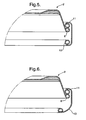
- Figure 5 shows the inward top curl 11 resting on the outward disc curl 8 at a section through the lower curl 12 and figure 6 shows the same closure at a section through the lower lug 13.
- Figures 7 and 8 show the closure of figures 2 and 3 , closing a glass jar 20.
- the closure When the closure is applied to a glass jar, the top of the jar presses into sealing material 9 forming an imprint and improved seal 10.
- the skirt (ring) is rotated and the lug 13 is moved under the thread 21 to pull the disc down.
- a lug 13 contacts screw thread 21 at position 'X'.
- the contact point of curls 8 and 12 is shown as 'Y'.
- the effective lug thickness which is the axial distance between X and Y, is distance 'A'.
- the axial (vertical) distance from the uppermost part 'Z' of compressed material (seal 10) to the bottom of disc curl 8 is 'B'.
- the distance from the glass finish (top of the container) to the top of thread 21 is 'C'.
- FIG 11 An alternative version as shown in figure 11 has an outward curl 8'.
- Figure 11 also shows how the sealing material 9 may be contained more locally by shaping the disc 2 into two parts: an upper annulus or horizontal portion 7a adjacent the shoulder 6 and a depending or vertical portion 7b, which terminates in an outward curl 8'. This is, of course an option which may be used in any of the other embodiments of the invention.
- Figure 11 shows the ring above the level of the top of groove 5 as it is in a "ring over disc” closure.
- FIG. 12 and 13 which is also of the "ring over disc” type, has a disc with inward curl 8, inclined shoulder 6 and single part annulus 7.
- the "ring over disc” closures have uppermost part of disc 3 lower than the top of the skirt, which may assist tightening of the skirt during closing. Over-tightening of the container may be avoided by flexing of the skirt in combination with the disc and at most the skirt will become level with the disc.
- FIG. 14a shows the skirt 3' alone.
- the top projection 11' is in four parts, with lugs 13 positioned below gaps between projections 11'. If the skirt 3' is made from plastic, the ejection of the skirt from the mould is easier, as is insertion of the metal disc 2 into the more flexible skirt.
- closure may include, are flats or similar undulations 14 around the disc which form gaps 15 when inserted in skirt 3 ( figures 15 and 16 ). This provides a ventilation path and drying of the spaces between the skirt, disc and container is improved after filling.
Description
- This invention relates to a closure. In particular, it relates to the combination of a closure and a container, the container typically including threads. The closure is of the two-part type of twist closure, which comprises an inner cap or disc part, and a ring or skirt part.
- Two-part closures typically comprise a cap or disc which is held onto a container by a skirt, which is sometimes referred to as a ring, or overcap. The two parts may be of the same material, or different materials as in a combination closure or "combo-cap" which uses a metal disc and a plastic skirt. The skirt often defines threads or lugs, which cooperate with complementary features on a container neck. Sealing material is conventionally applied to the disc to form a seal between the disc and the mouth of the container.
- There are many examples of two-part closures, of which
US 3446381 A (PODESTA ET AL ) is one of the older examples. That patent describes a two-part metallic cap with a separate disc and "sleeve-like" skirt. Another two-piece metallic cap from the same inventor is shown inUS 3836033 A (PODESTA ). InUS 3836033 A the disc has an edge portion which projects beyond the container mouth, an annular portion which sits on the top edge of the container mouth and a middle portion covering the opening of the container. The entire middle portion of the disc moves between concave and convex configurations by pivoting of the annular portion about the top edge of the container mouth. Both of these closures can be used for containers such as glass bottles, pots and the like. - It has also been popular to provide screw threads or lugs on the skirt, whether this is of metal or of plastics material. For example, the skirt may be part of a threaded outer cap, as in
US 4473163 B (ERNST ) in which the outer cap prises the inner cap off the container during unscrewing. This is particularly useful when the closure is used for the packaging of food products, which during processing "pull" a negative pressure, often called a "vacuum". This vacuum creates a substantial resistance to opening. The two-piece cap ofEP 1686070 A (PLATO PRODUCT CONSULTANTS V.O.F.) has a special feature to reduce torque on opening. This feature is similar to a dimple, which during opening, pushes up a disc-shaped inner cap to overcome the forces between jar and closure, which create the sealing of the package. - The 2-piece twist closure design allows the breaking of the container seal to be controlled. The initial twisting of the skirt is sometimes used to activate a tamper-evident feature, such as breaking a tamper-evident band, whilst the disc remains sealed to the container. Thereafter, a further feature may be provided on the skirt to prise the disc from the container, thereby breaking the seal between the disc and the container to equalise any difference between the internal pressure in the container and the external environment. This 2-stage opening reduces the torque required to open the closure and allows the closure to be removed more easily.
- Although known features such as these can reduce the force necessary to break vacuum, there are still problems inherent in the combined opening force requirements of unscrewing and breaking the vacuum. This invention seeks to overcome those problems.
- According to the present invention, there is provided a recloseable two-part all-metal twist closure comprising a disc and a skirt, in which the disc has a seal and a surrounding rim and is held within the skirt moveably between an inwardly projecting rim at the upper end of the skirt and either an annular inward projection on the skirt wall and/or lugs at the lower end of the skirt wall, the closure being adapted for use with a container and the sum of the distance (B) between the seal and the contact point of the disc rim and lower skirt rim, plus the effective thickness (A) of the lugs is greater than the distance (C) between the top of threads on the container and the top of the container.
- The term "disc" is used to define the whole of an inner cap component and is not intended to infer that that component is simply a thin circular component. Preferably, the centre portion of the disc is a substantially flat planar panel and radially outwardly of this panel the disc is profiled for sealing a container to which the closure is attached, as discussed in more detail below.
- It is thus possible to manufacture the closure of the invention from fairly stiff material, for example from a single piece of metal (e.g. steel) and as described in
WO/2008/053014 . In any event, the closure disc is not intended to be overly flexible or moveable from concave to convex and returning to concave as is required inUS 3836033 A , which is equivalent toFR 2177118 - The effective thickness of the lugs is the axial distance (A) between a position (X), which is the contact point between the lug and the top of the container thread, and a position (Y), which is the contact point of disc rim and skirt rim. The references refer to
figures 9 and10 of this application. Clearly the invention is only applicable to closures, which have a skirt depth that is more than that of a simple overcap or lid. - The container, which the closure of the invention is suitable to close, may be a jar or bottle (of glass or plastics material) or even a metal can. Although a usual use for the closure of the invention would be with a glass jar, the expressions are used interchangeably in this application. The jar generally includes threads but one or more waves, cams or projections may be used in the place of threads. A single continuous thread, as in a rolled-on thread, may also be provided on the jar.
- During opening of the closure of the invention, the first stage of torque application to rotate the skirt and release the lug from the underside of the thread is distinctly separate from the second stage which is needed to prise the disc axially away from the container by forcing the lugs between the top of the threads and the underside of the disc rim. There is thus no effort required to slide the seal of the disc part relative to the top of the jar and the disc may audibly jump when the seal is broken on first opening.
- The strength of the lugs required to prise the disc from the jar during opening is less than that required for lugs on a conventional twist closure as the lugs of the present invention only have to resist crushing between the thread and the disc and do not have to resist bending. Thinner material may thus be used to form the skirt. Although the disc is typically of metal for optimum barrier properties, for example, the skirt may be a plastics material or metal.
- The invention is an all-metal closure so that if both parts of the closure were made from the same piece of metal, this would result in cost saving, environmental and resources conservation, even if the panels and rings were mixed and matched from the metal sheets or discs from which they were formed. Also, the metal could be decorated, and decoration of skirt (ring) and disc matched for aesthetic purposes for example.
- The metal of the closure is preferably steel. The thickness of steel may be less than that used for the manufacture of vacuum twist closures. Thus the steel used for the closures of the present invention may be less than 0.14mm for closures of 48mm nominal diameter and below, less than 0.15mm for closures of 48mm nominal diameter and below, less than 0.16mm for closures of 66mm nominal diameter and below, less than 0.17mm for closures of 77mm nominal diameter and below, less than 0.18mm for closures of 82mm nominal diameter and below, and less than 0.20mm for closures of 110mm nominal diameter and below. The metal may be a polymer-coated metal.
- Generally, the inwardly projecting rim on the top of a metal skirt is curled inwardly to hide the upper cut edge. Not only does this enhance the appearance of the skirt, but it also provides a safe edge. The lower end of the skirt is also usually curled inwardly to obscure the lower cut edge of the skirt and to provide a smooth surface against which to push the rim of the disc part during opening. The rim of a metal disc part is usually curled (inwardly or outwardly) to obscure the cut edge of the disc and the disc part may be sealed or even filled with compound or sealing material. Cut edge protection may be enhanced by conventional processes such as by the use of roller-coated lacquers. Of course it is possible for all cut edges to be coated after cutting.
- The radius of curvature of any of the curled regions, either on skirt or disc, is typically no less than 0.4 mm This gives a good appearance and smooth feel, and avoids damage to decoration or protective coatings, which could occur if the curl is too tight, for example.
- The inwardly projecting rim on the top end of the skirt part may be discontinuous so that inwardly projecting rim portions are only provided where there is no lug opposite. This simplifies manufacture of the ring, particularly if the ring is made from plastic because ejection from the mould is simpler and insertion of the disc into a more flexible ring is easier.
- In one embodiment, the height of the disc rim may vary around its circumference. Another alternative is for the height or thickness of the skirt lugs or adjacent curled regions to vary. In yet another embodiment, the height or thickness of the top of the container threads may vary. Any of these alternatives have the advantage that during the second stage of opening, the force to prise the disc from the top of the container is focussed at one part of the circumference, and so less torque is required.
- Either or both of the surfaces of the disc and skirt, which contact one another when the container is closed, may undulate or include protrusions/dimples to provide a gap or gaps between the skirt and disc. This reduces the area, which might stick during handling and any gap or gaps provide ventilation between the skirt and disc. Spaces between skirt, disc and container dry more effectively in these closures after filling and closing a container. Furthermore, accidental movement of the skirt may be avoided and evidence of movement such as opening may be provided. Flexibility of the panel and/or ring allows release of stuck surfaces either individually (disc/ring) or when assembled into closures. Addition of solid or liquid slip material or non-stick coatings may limit application torque and minimise sticking.
- For tamper evidence or to avoid accidental movement of the ring, the skirt may be joined to the disc by a breakable material or strap.
- When the closure is used to close a container, the top of the skirt in one embodiment is typically a little higher than the top of the disc before the closure is tightened onto the jar, and may flex slightly in combination with the disc to become substantially level when the desired tightness is achieved. Over-tightening of the closure in so-called "top-belt driven cappers" may thus be avoided.
- Although the closure of the invention does not require the entire middle portion of the disc to move between concave and convex as described in
US 3836033 , it is common for the middle portion of closures of different types to have a small central bi-stable part or "button" which moves when internal vacuum is released and vice versa. This vacuum button feature may be included in the disc of our invention but it plays no part in any pivoting or in the sealing of the container itself. - Preferred embodiments of the invention will now be described, by way of example only, with reference to the drawings, in which:
-
-
Figures 1A and 1B are partial side sections of an all-metal closure with an annular projection on skirt wall; -
Figure 2 is a partial side section through a curl of a closure with plain wall; -
Figure 3 is a partial side section through a lug of the closure offigure 2 ; -
Figure 4 is an underplan view showing four lugs; -
Figure 5 is a partial side section through a curl of an alternative closure with an outward disc curl; -
Figure 6 is the partial side section offigure 5 through a lug of the closure; -
Figure 7 is a partial side section through the curl of the closure offigures 2 and 3 in closed position on a jar; -
Figure 8 is a partial side section through a lug of the closure offigures 2 and 3 in closed position on a jar; -
Figure 9 is a partial side section through the curl of the closure offigures 2 and 3 , above a jar after opening; -
Figure 10 a partial side section through a lug of the closure offigures 2 and 3 , above a jar after opening; -
Figure 11 is a partial side section through a curl of a closure with an outward curl on the disc; -
Figure 12 is a partial side section through a curl of a closure, with the top of the ring above the disc; -
Figure 13 is a partial side section through a lug of the closure offigure 12 ; -
Figures 14a and 14b are perspective views of a closure ring and closure with four inwardly projecting rim portions opposite gaps between lugs; -
Figure 15 is a perspective view of a disc having "flats"; and -
Figure 16 is a perspective view of the disc offigure 15 , fitted in a ring. - Figures 1A and 1B are side sections of a two-part closure manufactured for example in accordance with unpublished patent application
PCT/EP2007/061744 metal disc 30, having its cut edge protected by acurl 32, and acircumferential ring 40. Thedisc 30 is trapped within thering 40 by twocurls Figure 1A is a section through acurl 43 andfigure 1B is a section through alug 44. - A retention feature, or features 45 is/are provided to position the
disc 30 loosely within thering 40, whilst allowing thedisc 30 freedom to move rotationally relative to thering 40 and limiting axial movement. Theretention feature 45 may take the form of spaced projections around the circumference of thering 40, or alternatively may be provided by a circumferential bead, either full or segmented. Achannel 34 is provided about the inside periphery of thedisc 30, surrounding a flat centre panel, and this channel is used to hold sealingmaterial 36. The provision of thechannel 34 ensures proper location of the sealing material to interface with the neck of acontainer 50 and also reduces the quantity of sealingmaterial 36 because of its better and more accurate distribution. A portion ofthread 52 is also shown infigures 1A and 1B . For opening, unscrewing of the closure causeslugs 44 to move overthreads 52, causingretention feature 45 to push upwards againstdisc curl 32, thereby raising thedisc 30 from thecontainer 50. -
Figures 2 and 3 show an all-metal two-part closure 1 having adisc part 2 and a skirt or ringpart 3.Disc 2 has a flatcentral panel 4, surrounded by upwardly extendinggroove 5,shoulder 6,annulus 7 and terminating ininward curl 8. Thegroove 5 is profiled so as to retain sealing material orother material 9, in this example from the edge of planarcentral panel 4 to thecurl 8. - The
skirt 3 offigures 2 and 3 has inward curls 11 and 12 at both upper and lower ends and lugs 13 (typically four, equi-spaced) around the lower edge. Thelugs 13 are shown most clearly in the underplan view offigure 4 . The top of the skirt (ring) infigures 2 and 3 is below the level of the top of thechannel 5, so that this embodiment is sometimes referred to as "ring below disc" or "disc over ring". - This ring below disc configuration has a smooth feel. When the closure is used to close a filled container, there is less risk of scuffing of the ring. For these reasons, this is the most preferred format for the invention. An alternative ring below disc closure may have the disc panel extending outside the top curl of the ring.
- When the container is a glass jar which is closed by the ring below disc closure, it is well suited for stacking. The top of the closure may nest with a stacking bead around the bottom rim of the jar above.
- In its form independently of any container, the
disc 2 is free to move between a lower position when the curl on the disc abutscurl 12 and/or lug 13, and an upper position, as shown, when the disc abutscurl 11. Theshoulder 6 of the disc offigures 2 and 3 contactsupper curl 11.Sealing material 9 could of course be contained more locally by shaping the disc. - Either curl may be inward or outward (reversed), with the ring above or below the panel. The curls may be partly or fully closed, rest on or in features of the
disc 2 orring 3, or other possible variants. In one arrangement, as shown infigures 5 and 6 , thedisc curl 8 may be outward and thetop curl 11 may be inward, such that the surface of thering curl 11 that was originally on one side (preferably the decorated side) of the metal sheet contacts the surface of thedisc curl 8 that was originally on the other side of the metal sheet. In this arrangement the contacting surfaces may have different coatings or one may not be coated at all, in order to avoid similar coatings sticking to one another, and the possibly undecorated surface of the outside of thedisc curl 8 may be hidden from view when looking from the outside of the closure.Figure 5 shows the inwardtop curl 11 resting on theoutward disc curl 8 at a section through thelower curl 12 andfigure 6 shows the same closure at a section through thelower lug 13. - Many features of the closures become more clear when closures are used to close a container. Although any screw container could be closed by any closure according to the invention, the drawings of
figures 7 to 10 show a glass jar, which has very distinct threads. -
Figures 7 and8 show the closure offigures 2 and 3 , closing aglass jar 20. When the closure is applied to a glass jar, the top of the jar presses into sealingmaterial 9 forming an imprint andimproved seal 10. The skirt (ring) is rotated and thelug 13 is moved under thethread 21 to pull the disc down. - The relative positions of
improved seal 10, underside ofdisc rim 24 and inwardly projectinglug 13 can be seen infigure 8 . The seal is defined by that part of the sealingmaterial 9 imprinted by thejar 20. - In the closed position of
figures 7 and8 ,shoulder 6 presses againstupper curl 11 on the skirt, and lugs 13 press against the underside ofthreads 21. In the closed position offigure 8 , the lug is under the thread of the glass jar, effectively pulling the disc into place and squeezing the sealing material. - Counter-rotation of the ring causes the lugs to move to positions above the adjacent threads and application of further torque causes lifting of the disc and full opening of the closure (see
figures 9 and10 ). In the open position, the user has rotated the ring such that thelug 13 is now resting on top of the thread portion 21 (figure 10 ) and the adjacent portion of thebottom curl 12 has moved to contact the bottom of the disc curl 8 (figure 9 ). Moving the curls into contact with each other raises the disc, thereby breaking the seal. - In the final position of
figure 10 , alug 13 contacts screwthread 21 at position 'X'. Infigure 9 , the contact point ofcurls disc curl 8 is 'B'. The distance from the glass finish (top of the container) to the top ofthread 21 is 'C'. - In order for the seal to be broken, it is necessary for the sum of distances A + B to be greater than distance C. This invention is therefore not applicable to shallow cap-like closures.
- An alternative version as shown in
figure 11 has an outward curl 8'.Figure 11 also shows how the sealingmaterial 9 may be contained more locally by shaping thedisc 2 into two parts: an upper annulus orhorizontal portion 7a adjacent theshoulder 6 and a depending orvertical portion 7b, which terminates in an outward curl 8'. This is, of course an option which may be used in any of the other embodiments of the invention. -
Figure 11 shows the ring above the level of the top ofgroove 5 as it is in a "ring over disc" closure. - The embodiment of
figures 12 and13 , which is also of the "ring over disc" type, has a disc withinward curl 8,inclined shoulder 6 andsingle part annulus 7. The "ring over disc" closures have uppermost part ofdisc 3 lower than the top of the skirt, which may assist tightening of the skirt during closing. Over-tightening of the container may be avoided by flexing of the skirt in combination with the disc and at most the skirt will become level with the disc. - It is conventional to provide curls where an exposed edge of cut metal might otherwise be dangerous during handling, to obscure edges for cosmetic purposes, or to protect against corrosion.
- Although the most preferred embodiments of closure shown in
figures 2 to 13 have all metal forms, it is clearly possible to have a metal disc and a plastic skirt. This enables the form shown infigures 14a and 14b to be made more easily, although it could still be made from metal.Figure 14a shows the skirt 3' alone. The top projection 11' is in four parts, withlugs 13 positioned below gaps between projections 11'. If the skirt 3' is made from plastic, the ejection of the skirt from the mould is easier, as is insertion of themetal disc 2 into the more flexible skirt. - Other features, which the closure may include, are flats or
similar undulations 14 around the disc which formgaps 15 when inserted in skirt 3 (figures 15 and 16 ). This provides a ventilation path and drying of the spaces between the skirt, disc and container is improved after filling. - Although the invention has predominantly been described with reference to an all-metal closure and a glass jar, the scope of the invention is also intended to include changes and modifications to materials etc and numbers of features such as lugs, as defined by the scope of the claims.
Claims (9)
- A system comprising: a container (20) and a two-part closure (1), the two-part closure (1) comprising a disc (2) and a skirt (3), in which the disc (2) has a seal and a surrounding rim (7) and is held moveably between an inwardly projecting rim at the upper end of the skirt (3) and lugs (13) at the lower end of the skirt wall, the closure (1) being adapted for use with the container (20) and characterised in that the sum of the distance (A+B) between the seal and the contact point of the disc rim and lower skirt rim (B), plus the effective thickness of the lugs (A) is greater than the distance (C) between the top of threads (21) on the container (20) and the top of the container.
- A system according to claim 1, in which the top of the skirt is lower than the top of the disc ("ring below disc"), or vice versa, with the top of the skirt higher than the top of the disc ("ring above disc").
- A system according to claim 1 or claim 2, in which the disc and skirt are both made of metal.
- A system according to claim 3, in which the metal from which the disc is formed in a single piece of decorated metal.
- A system according to claim 3 or claim 4, in which the metal is steel having a thickness, which is less than that used for the manufacture of vacuum twist closures of the same diameter.
- A system according to any of claims 3 to 5, in which the inwardly projecting rim on the top of a metal skirt is curled inwardly and the lower end of the skirt (3) is curled inwardly.
- A system according to any one of claims 3 to 6, in which the rim of the metal disc (2) is curled either inwardly or outwardly and, optionally, includes sealing material.
- A system according to claim 6 or claim 7, in which the curl or curls (8, 11, 12) are no less than 0.4 mm.
- A system according to any one of claims 1 to 8, in which the inwardly projecting rim on the top end of the skirt (3) is discontinuous, so that inwardly projecting rim portions are only provided where there is no lug opposite.
Priority Applications (2)
| Application Number | Priority Date | Filing Date | Title |
|---|---|---|---|
| EP09723370A EP2254806B1 (en) | 2008-03-20 | 2009-02-12 | Closure |
| PL09723370T PL2254806T3 (en) | 2008-03-20 | 2009-02-12 | Closure |
Applications Claiming Priority (4)
| Application Number | Priority Date | Filing Date | Title |
|---|---|---|---|
| EP08153134 | 2008-03-20 | ||
| GB0810511A GB0810511D0 (en) | 2008-06-10 | 2008-06-10 | Closure |
| EP09723370A EP2254806B1 (en) | 2008-03-20 | 2009-02-12 | Closure |
| PCT/EP2009/051630 WO2009115377A1 (en) | 2008-03-20 | 2009-02-12 | Closure |
Publications (2)
| Publication Number | Publication Date |
|---|---|
| EP2254806A1 EP2254806A1 (en) | 2010-12-01 |
| EP2254806B1 true EP2254806B1 (en) | 2013-04-03 |
Family
ID=40651765
Family Applications (1)
| Application Number | Title | Priority Date | Filing Date |
|---|---|---|---|
| EP09723370A Active EP2254806B1 (en) | 2008-03-20 | 2009-02-12 | Closure |
Country Status (14)
| Country | Link |
|---|---|
| US (2) | US8636161B2 (en) |
| EP (1) | EP2254806B1 (en) |
| CN (1) | CN101977821B (en) |
| AU (1) | AU2009226818B2 (en) |
| BR (1) | BRPI0907975B1 (en) |
| CA (1) | CA2718069C (en) |
| DK (1) | DK2254806T3 (en) |
| EA (1) | EA019267B1 (en) |
| ES (1) | ES2411931T3 (en) |
| MX (1) | MX2010009349A (en) |
| PL (1) | PL2254806T3 (en) |
| PT (1) | PT2254806E (en) |
| WO (1) | WO2009115377A1 (en) |
| ZA (1) | ZA201005844B (en) |
Families Citing this family (30)
| Publication number | Priority date | Publication date | Assignee | Title |
|---|---|---|---|---|
| US8424706B2 (en) * | 2006-10-02 | 2013-04-23 | Crown Packaging Technology, Inc. | Closure with sealing insert |
| EP1918041A1 (en) * | 2006-10-31 | 2008-05-07 | Crown Packaging Technology, Inc | Metal closure with disc and method for producing such a metal closure with separate disc and ring from a single closure blank |
| CA2718069C (en) | 2008-03-20 | 2015-11-24 | Crown Packaging Technology, Inc. | Closure |
| GB0909189D0 (en) | 2009-05-29 | 2009-07-15 | Crown Packaging Technology Inc | Closure assembly |
| WO2012143322A1 (en) | 2011-04-20 | 2012-10-26 | Crown Packaging Technology, Inc. | Method for forming a metal closure |
| EP2662296A1 (en) * | 2012-05-08 | 2013-11-13 | Crown Packaging Technology Inc | Container with twist-off closure |
| US8910781B2 (en) * | 2013-01-11 | 2014-12-16 | R.J. Reynolds Tobacco Company | Container for smokeless tobacco products and related packaged product assembly and method |
| JP6437513B2 (en) * | 2013-03-13 | 2018-12-12 | アボット・ラボラトリーズAbbott Laboratories | Keyed caps for containers and related devices and systems |
| US10689164B2 (en) * | 2014-01-03 | 2020-06-23 | Sonoco Development, Inc. | Container with heat-sealed composite plastic and metal screw closure |
| US10040593B2 (en) | 2014-02-07 | 2018-08-07 | Ball Corporation | Metallic container with a threaded closure |
| EP3194286A1 (en) | 2014-08-20 | 2017-07-26 | Crown Packaging Technology, Inc. | Lug closure |
| TWD172383S (en) * | 2015-03-17 | 2015-12-11 | 溫芫鋐 | Part of the heat dissipation structure of the cooling pad |
| US9445631B1 (en) | 2015-03-20 | 2016-09-20 | R. J. Reynolds Tobacco Company | Container for smokeless tobacco products and related packaged product assembly and method |
| US9671029B2 (en) * | 2015-09-26 | 2017-06-06 | Te-Feng Lin | Lid of gas pressure regulator |
| USD827364S1 (en) * | 2016-03-24 | 2018-09-04 | Brita Gmbh | Lid for a drinking vessel |
| US20180044155A1 (en) | 2016-08-12 | 2018-02-15 | Ball Corporation | Apparatus and Methods of Capping Metallic Bottles |
| US11365035B2 (en) | 2016-12-07 | 2022-06-21 | Tecnocap, Llc | Seal releasing closure assembly |
| US11370579B2 (en) | 2017-02-07 | 2022-06-28 | Ball Corporation | Tapered metal cup and method of forming the same |
| US10875076B2 (en) | 2017-02-07 | 2020-12-29 | Ball Corporation | Tapered metal cup and method of forming the same |
| US10875684B2 (en) | 2017-02-16 | 2020-12-29 | Ball Corporation | Apparatus and methods of forming and applying roll-on pilfer proof closures on the threaded neck of metal containers |
| MX2020002563A (en) | 2017-09-15 | 2020-07-13 | Ball Corp | System and method of forming a metallic closure for a threaded container. |
| USD950318S1 (en) | 2018-05-24 | 2022-05-03 | Ball Corporation | Tapered cup |
| JP7170131B2 (en) | 2018-11-05 | 2022-11-11 | ボール コーポレイション | A metal container with a threaded closure |
| USD906056S1 (en) | 2018-12-05 | 2020-12-29 | Ball Corporation | Tapered cup |
| USD968893S1 (en) | 2019-06-24 | 2022-11-08 | Ball Corporation | Tapered cup |
| EP3990201A4 (en) | 2019-06-26 | 2023-07-26 | Ball Corporation | A method and apparatus for sealing a metallic container with a metallic end closure |
| USD953811S1 (en) | 2020-02-14 | 2022-06-07 | Ball Corporation | Tapered cup |
| USD974845S1 (en) | 2020-07-15 | 2023-01-10 | Ball Corporation | Tapered cup |
| USD1012617S1 (en) | 2021-02-22 | 2024-01-30 | Ball Corporation | Tapered cup |
| WO2022187190A1 (en) * | 2021-03-01 | 2022-09-09 | Ball Corporation | Metal container and end closure with seal |
Family Cites Families (136)
| Publication number | Priority date | Publication date | Assignee | Title |
|---|---|---|---|---|
| US244065A (en) * | 1881-07-12 | Felicie p | ||
| US526740A (en) * | 1894-10-02 | rapaport | ||
| US612196A (en) * | 1898-10-11 | And stephen | ||
| US536975A (en) * | 1895-04-02 | Electrically-controlled magnet and valve for pipe-organs | ||
| US240595A (en) * | 1881-04-26 | laraway | ||
| US266906A (en) * | 1882-10-31 | Earthenware jug | ||
| US489005A (en) * | 1893-01-03 | Elevator-indicator | ||
| US192757A (en) * | 1877-07-03 | Improvement in corn-planters | ||
| US3124872A (en) | 1964-03-17 | Method and apparatus for severing a continuous | ||
| US522364A (en) * | 1894-07-03 | Hot-air furnace | ||
| US480304A (en) * | 1892-08-09 | Planter | ||
| US470529A (en) * | 1892-03-08 | williams | ||
| US628894A (en) * | 1898-06-06 | 1899-07-11 | John Outcalt | Weighing-machine. |
| US1349837A (en) | 1917-03-24 | 1920-08-17 | American Can Co | Double-seamer |
| US1699069A (en) | 1924-06-09 | 1929-01-15 | Huntar Felix | Can-double-seaming machine |
| FR620920A (en) | 1926-06-04 | 1927-05-02 | Process for the production of box closures | |
| US1884699A (en) | 1929-03-02 | 1932-10-25 | American Can Co | Method of making friction closures |
| FR769264A (en) | 1933-05-20 | 1934-08-23 | Improved manufacturing process for metal box closures, and closures obtained by this process | |
| US2139682A (en) | 1933-06-20 | 1938-12-13 | American Can Co | Container body forming and cutting mechanism |
| US2197439A (en) | 1936-03-14 | 1940-04-16 | Crown Can Company | Can and method of making the same |
| US2166923A (en) | 1938-01-28 | 1939-07-18 | Atlantic Refining Co | Recessing device |
| US2216082A (en) | 1938-05-06 | 1940-09-24 | Continental Can Co | Roller mounting for can head seaming apparatus |
| US2527885A (en) | 1946-02-13 | 1950-10-31 | Fmc Corp | Container closing machine |
| US2621622A (en) | 1946-03-14 | 1952-12-16 | Continental Can Co | Method of forming ringlike bodies |
| US2522301A (en) | 1947-05-24 | 1950-09-12 | Walter E Rooney | Double seamer |
| US2702597A (en) | 1949-04-15 | 1955-02-22 | Automatic Steel Products Inc | Rotary cup trimmer with scrap cutter |
| US2975740A (en) | 1956-10-10 | 1961-03-21 | W F & John Barnes Company | Can end seamer |
| US2991602A (en) | 1957-03-21 | 1961-07-11 | Kerke Kornelis Van De | Process for producing a folded rim on a container of plastic material, as well as anapparatus for carrying out this process |
| US3085324A (en) | 1959-04-01 | 1963-04-16 | Aluminum Co Of America | Method of making two-piece closure caps |
| CH385596A (en) | 1959-06-24 | 1964-12-15 | Haemmerle Ag | Sheet metal working machine |
| US3068344A (en) | 1960-07-06 | 1962-12-11 | Continental Can Co | Combination electrical and mechanical can separating means on continuous welding machines |
| US3186003A (en) | 1961-12-01 | 1965-05-25 | Flight Res Inc | Variable shutter mechanism |
| US3380419A (en) | 1963-10-10 | 1968-04-30 | Continental Can Co | Method of making closure caps |
| NL6606729A (en) | 1965-05-19 | 1966-11-21 | ||
| US3581691A (en) | 1969-04-17 | 1971-06-01 | Gulf & Western Ind Prod Co | Apparatus and method for trimming can bodies |
| IT953394B (en) * | 1972-03-23 | 1973-08-10 | Podesta A | SCREW OR BAYONET METAL CAPSULE WITH SEPARATE BOTTOM FOR CLOSING THE CONTAINERS |
| US3802362A (en) | 1972-09-26 | 1974-04-09 | Union Special Maschinenfab | Control system for pneumatic thread aligner |
| US3813972A (en) | 1973-01-04 | 1974-06-04 | American Can Co | Cutting means |
| US3802363A (en) | 1973-01-24 | 1974-04-09 | Kaiser Aluminium Chem Corp | Can trimmer device |
| GB1415287A (en) | 1973-02-20 | 1975-11-26 | Schuler Gmbh L | Device for parting sheet metal containers |
| GB1536543A (en) | 1975-01-13 | 1978-12-20 | Metal Box Co Ltd | Containers |
| US4030432A (en) | 1975-01-24 | 1977-06-21 | Gulf & Western Manufacturing Company (Hastings) | Can trimming apparatus |
| US4022141A (en) | 1975-09-09 | 1977-05-10 | Vermont Marble Company | Machine for seaming together a lid and a container |
| USD244065S (en) | 1975-09-10 | 1977-04-19 | Dart Industries Inc. | Serving bowl or the like |
| US4004478A (en) | 1976-01-20 | 1977-01-25 | F. L. Smithe Machine Company, Inc. | Apparatus for adjusting the position of a rotatable cutter mechanism |
| US4003324A (en) | 1976-02-04 | 1977-01-18 | The Continental Group, Inc. | End trimmer |
| GB1577739A (en) | 1976-04-09 | 1980-10-29 | Metal Box Co Ltd | Containers |
| US4111330A (en) * | 1977-10-31 | 1978-09-05 | The Continental Group, Inc. | Reclosable vacuum container |
| USRE30746E (en) | 1978-03-09 | 1981-09-22 | Belgium Tool & Die Company | Can cutting apparatus and method |
| US4171063A (en) | 1978-05-30 | 1979-10-16 | Cloutier John G | Containers for paints and other coating materials |
| CH629983A5 (en) | 1978-06-06 | 1982-05-28 | Alusuisse | METHOD FOR PRODUCING LID RINGS FOR CAN CAN. |
| DE2933547A1 (en) * | 1979-07-26 | 1981-03-12 | Schweizerische Aluminium AG, 3965 Chippis | Mfr. of lid and lid ring - uses deep-drawing of recesses for lid and ring, in sheet metal blank |
| US4299147A (en) | 1979-09-06 | 1981-11-10 | Donald V. Hanlon | Method and apparatus for cutting can bodies |
| CA46244S (en) | 1979-10-04 | 1979-11-19 | Arnoldware Rogers Canada Ltee | Container lid |
| CH657589A5 (en) | 1981-11-19 | 1986-09-15 | Ernst & Co Inh Geiger & Neuens | SCREW CAP WITH INTERNAL AND EXTERNAL COVER. |
| NL8201681A (en) | 1982-04-22 | 1983-11-16 | Lindner Ind | SEALING COVER FOR SEALING A HOLDER UNDER VACUUM (VACUUM SNAP CAP). |
| US4487539A (en) | 1983-01-24 | 1984-12-11 | American Can Company | Method and apparatus for the scoring and parting of can bodies |
| USD286026S (en) | 1983-05-27 | 1986-10-07 | Metal Box Plc | Lid for a container |
| US4557167A (en) | 1984-08-03 | 1985-12-10 | Cvacho Daniel S | Apparatus for trimming a scrap ring from a cylindrical container body and method of operation |
| USD291971S (en) | 1985-03-05 | 1987-09-22 | Sealright Co., Inc. | Container lid |
| JPH0636949B2 (en) | 1985-06-10 | 1994-05-18 | 北海製罐株式会社 | Neck-in can body manufacturing method |
| US4671148A (en) | 1985-09-16 | 1987-06-09 | Thatcher Alan J | Trimmer for cylindrical objects |
| US4762579A (en) | 1985-12-03 | 1988-08-09 | Toyo Seikan Kaisha, Ltd. | Process for producing easily openable closure |
| JPH0239633Y2 (en) | 1986-02-25 | 1990-10-24 | ||
| US5146818A (en) | 1988-04-13 | 1992-09-15 | H. L. Fisher Mfg. Co., Inc. | Can trimming apparatus |
| US4914990A (en) | 1988-04-13 | 1990-04-10 | H. L. Fisher Mfg. Co., Inc. | Apparatus for trimming flanged cans |
| KR920011036B1 (en) | 1988-04-27 | 1992-12-26 | 호까이 세이칸 가부시끼가이샤 | Apparatus for seaming can end |
| US4942777A (en) | 1989-03-13 | 1990-07-24 | Fife Morton E | Device for cyclically varying the phase relationship between two rotating shafts |
| IT1231550B (en) | 1989-04-04 | 1991-12-17 | Wemex Italia Spa | EQUIPMENT FOR SCRATCHING THE LIDS OF BOXES, JARS AND SIMILAR METAL CONTAINERS, IN PARTICULAR OF JARS FOR FOOD PRODUCTS |
| MX9101632A (en) | 1990-10-22 | 1992-06-05 | Ball Corp | METHOD AND APPARATUS TO REINFORCE THE BASE OR BOTTOM OF A CONTAINER |
| JPH0538526A (en) | 1991-08-05 | 1993-02-19 | Toyota Motor Corp | Method for ironing and trimming cylinder part in preform |
| GB9224463D0 (en) | 1992-11-23 | 1993-01-13 | Metal Box Plc | Closure for container |
| USD359451S (en) | 1993-08-11 | 1995-06-20 | Dees Kent L | Beverage can cap with magnet |
| US5694822A (en) | 1993-08-16 | 1997-12-09 | Reynolds Metals Company | Apparatus for trimming can bodies |
| DE4335580C2 (en) | 1993-10-19 | 2002-07-11 | Krupp Kunststofftechnik Gmbh | Device for separating a can frame several times high |
| GB9422228D0 (en) | 1994-11-03 | 1994-12-21 | Metal Box Plc | Seaming method and apparatus |
| US5564321A (en) | 1995-04-03 | 1996-10-15 | Rath; Hans M. | Can trimmer |
| US5785198A (en) * | 1995-09-18 | 1998-07-28 | The Coca-Cola Company | Twist-off can end |
| USD492596S1 (en) | 2000-02-29 | 2004-07-06 | Tri State Distribution, Inc. | Bottle cap |
| USD489005S1 (en) | 2001-02-28 | 2004-04-27 | Tri State Distribution, Inc. | Bottle cap |
| US6564683B1 (en) | 2001-11-06 | 2003-05-20 | Jimmy Tsai | Multi-height can body cutting apparatus adapted to cut can body of different heights |
| USD480304S1 (en) | 2002-01-04 | 2003-10-07 | Container Development, Ltd. | Can end |
| USD471453S1 (en) | 2002-01-04 | 2003-03-11 | Container Development, Ltd | Can end |
| US6662958B2 (en) | 2002-01-31 | 2003-12-16 | Crown Cork & Seal Technologies Corporation | Composite closure having disk tightening feature |
| US6748835B2 (en) | 2002-02-05 | 2004-06-15 | Metal Container Corporation, Inc. | Container trimming apparatus |
| AR038867A1 (en) | 2002-03-07 | 2005-02-02 | Brasilata Embalagens Metalicas | PLASTIC COVER FOR CAN |
| USD482967S1 (en) | 2002-03-11 | 2003-12-02 | Ocean Spray Cranberries, Inc. | Cap |
| US7250352B2 (en) | 2002-04-24 | 2007-07-31 | Sanyo Electric Co., Ltd. | Methods for manufacturing a hybrid integrated circuit device |
| EP1375025A1 (en) | 2002-06-27 | 2004-01-02 | Alcan Technology & Management AG | Method of making a container body and container end bordering ring |
| US7014060B2 (en) * | 2002-07-19 | 2006-03-21 | Ball Corporation | Twist opening sealing container |
| EP1611981A4 (en) | 2003-04-09 | 2008-08-27 | Honda Motor Co Ltd | Cutting device for thin metallic plate |
| USD485179S1 (en) | 2003-06-03 | 2004-01-13 | Kaboum.Com Inc. | Lid for a drinking can |
| BR0303833B1 (en) | 2003-09-12 | 2012-08-07 | improvement in can closure arrangement. | |
| US7575133B2 (en) | 2003-10-06 | 2009-08-18 | Crown Cork & Seal Technologies Corporation | Bi-can having internal bag |
| US7526938B2 (en) | 2003-12-29 | 2009-05-05 | Crown Packaging Technology, Inc. | Can manufacture |
| EP1686070A1 (en) * | 2005-01-26 | 2006-08-02 | Plato product consultants V.O.F. | Easy opening closure |
| US20060191933A1 (en) | 2005-02-25 | 2006-08-31 | Seaquist Closures Foreign, Inc. | Closure system with improved sealing of lid |
| USD522364S1 (en) | 2005-02-25 | 2006-06-06 | Seaquist Closures Foreign, Inc. | Closure |
| SE528811C2 (en) | 2005-03-16 | 2007-02-20 | Sandvik Intellectual Property | Cuts and tools for chip separating machining with angled engaging means, and additives for such tools |
| USD526740S1 (en) | 2005-04-12 | 2006-08-15 | Zreative Product Inc. | Lighter |
| USD531505S1 (en) | 2005-10-21 | 2006-11-07 | Portola Packaging, Inc. | Container closure |
| USD529804S1 (en) | 2005-10-21 | 2006-10-10 | Portola Packaging, Inc. | Container closure |
| USD536975S1 (en) | 2005-11-18 | 2007-02-20 | Seaquist Closures Foreign, Inc. | Closure |
| USD542656S1 (en) | 2005-12-28 | 2007-05-15 | Silgan White Cap Americas Llc | Closure cap |
| USD542655S1 (en) | 2005-12-28 | 2007-05-15 | Silgan White Cap Americas Llc | Closure cap |
| USD645349S1 (en) | 2006-06-07 | 2011-09-20 | Kraft Foods Global Brands Llc | Container |
| EP1918041A1 (en) | 2006-10-31 | 2008-05-07 | Crown Packaging Technology, Inc | Metal closure with disc and method for producing such a metal closure with separate disc and ring from a single closure blank |
| USD567087S1 (en) | 2007-05-31 | 2008-04-22 | Rieke Corporation | Closing cap for a container closure, as installed, with retaining ring |
| USD564878S1 (en) | 2007-05-31 | 2008-03-25 | Rieke Corporation | Closing cap for a container closure |
| USD567081S1 (en) | 2007-05-31 | 2008-04-22 | Rieke Corporation | Bail handle for a closing cap |
| ITMO20070333A1 (en) | 2007-11-08 | 2009-05-09 | Sacmi | CAPSULE, APPARATUS AND METHOD |
| US8091455B2 (en) | 2008-01-30 | 2012-01-10 | Cummins Filtration Ip, Inc. | Apparatus, system, and method for cutting tubes |
| CA2718069C (en) | 2008-03-20 | 2015-11-24 | Crown Packaging Technology, Inc. | Closure |
| GB0807237D0 (en) | 2008-04-21 | 2008-05-28 | Crown Packaging Technology Inc | Cutting method and apparatus |
| US8122747B2 (en) | 2008-06-03 | 2012-02-28 | Stolle Machinery Company, Llc | Can end scoring method, and tooling assembly and conversion press therefor |
| USD608638S1 (en) | 2008-09-26 | 2010-01-26 | CBE-Campanhia Brasileira de Embalagens | Protective seal for use in cans or the like for packaging beverages or the like |
| USD625190S1 (en) | 2008-12-04 | 2010-10-12 | Cbe-Companhia Brasileira De Embalagens S/A | Protective seal for use in cans or the like for packaging beverages or the like |
| USD612196S1 (en) | 2009-01-27 | 2010-03-23 | Rubbermaid Incorporated | Food storage container lid |
| AU325726S (en) | 2009-02-03 | 2009-04-20 | Spillip Pty Ltd | A seal for containers |
| USD651081S1 (en) | 2009-11-11 | 2011-12-27 | Crown Packaging Technology, Inc. | Closure cap |
| CA135390S (en) | 2009-11-11 | 2011-01-10 | Crown Packaging Technology Inc | Closure cap |
| AU331470S (en) | 2009-11-11 | 2010-06-24 | Crown Packaging Tech | Closure cap |
| USD650669S1 (en) | 2010-05-11 | 2011-12-20 | Crown Packaging Technology, Inc. | Closure cap |
| USD656818S1 (en) | 2010-05-11 | 2012-04-03 | Crown Packaging Technology, Inc. | Closure cap |
| USD645741S1 (en) | 2010-05-11 | 2011-09-27 | Crown Packaging Technology, Inc. | Closure cap |
| USD650670S1 (en) | 2010-05-11 | 2011-12-20 | Crown Packaging Technology, Inc. | Closure cap |
| USD652297S1 (en) | 2010-05-11 | 2012-01-17 | Crown Packaging Technology, Inc. | Closure cap |
| USD650275S1 (en) | 2010-05-11 | 2011-12-13 | Crown Packaging Technology, Inc. | Closure cap |
| USD641622S1 (en) | 2010-06-10 | 2011-07-19 | Crown Packaging Technology, Inc. | Full aperture open beverage can |
| USD682106S1 (en) | 2010-07-08 | 2013-05-14 | Crown Packaging Technology, Inc. | Closure cap |
| USD682107S1 (en) | 2010-07-08 | 2013-05-14 | Crown Packaging Technology, Inc. | Closure cap |
| USD682105S1 (en) | 2010-07-08 | 2013-05-14 | Crown Packaging Technology, Inc. | Closure cap |
| USD682104S1 (en) | 2010-07-08 | 2013-05-14 | Crown Packaging Technology, Inc. | Closure cap |
| USD681459S1 (en) | 2010-07-08 | 2013-05-07 | Crown Packaging Technology, Inc. | Closure cap |
| USD664035S1 (en) | 2010-07-21 | 2012-07-24 | Apex Biotechnology Corp. | Cap for waterproof container |
| USD640556S1 (en) | 2010-12-03 | 2011-06-28 | Rexam Closures And Containers Inc. | Dispensing closure |
-
2009
- 2009-02-12 CA CA2718069A patent/CA2718069C/en active Active
- 2009-02-12 US US12/922,989 patent/US8636161B2/en active Active
- 2009-02-12 EA EA201071105A patent/EA019267B1/en not_active IP Right Cessation
- 2009-02-12 CN CN200980110609.1A patent/CN101977821B/en active Active
- 2009-02-12 MX MX2010009349A patent/MX2010009349A/en active IP Right Grant
- 2009-02-12 PL PL09723370T patent/PL2254806T3/en unknown
- 2009-02-12 WO PCT/EP2009/051630 patent/WO2009115377A1/en active Application Filing
- 2009-02-12 AU AU2009226818A patent/AU2009226818B2/en active Active
- 2009-02-12 ES ES09723370T patent/ES2411931T3/en active Active
- 2009-02-12 PT PT97233704T patent/PT2254806E/en unknown
- 2009-02-12 EP EP09723370A patent/EP2254806B1/en active Active
- 2009-02-12 DK DK09723370.4T patent/DK2254806T3/en active
- 2009-02-12 BR BRPI0907975-0A patent/BRPI0907975B1/en active IP Right Grant
-
2010
- 2010-08-16 ZA ZA2010/05844A patent/ZA201005844B/en unknown
-
2014
- 2014-01-06 US US14/148,141 patent/US9387959B2/en active Active
Also Published As
| Publication number | Publication date |
|---|---|
| WO2009115377A1 (en) | 2009-09-24 |
| BRPI0907975A2 (en) | 2015-08-04 |
| CN101977821A (en) | 2011-02-16 |
| EA201071105A1 (en) | 2011-02-28 |
| MX2010009349A (en) | 2010-09-28 |
| US20140116979A1 (en) | 2014-05-01 |
| US20110011866A1 (en) | 2011-01-20 |
| DK2254806T3 (en) | 2013-06-24 |
| US9387959B2 (en) | 2016-07-12 |
| CN101977821B (en) | 2014-10-29 |
| CA2718069C (en) | 2015-11-24 |
| AU2009226818B2 (en) | 2014-02-27 |
| EP2254806A1 (en) | 2010-12-01 |
| ZA201005844B (en) | 2011-04-28 |
| CA2718069A1 (en) | 2009-09-24 |
| US8636161B2 (en) | 2014-01-28 |
| AU2009226818A2 (en) | 2010-10-14 |
| PT2254806E (en) | 2013-07-10 |
| AU2009226818A1 (en) | 2009-09-24 |
| ES2411931T3 (en) | 2013-07-09 |
| PL2254806T3 (en) | 2013-08-30 |
| BRPI0907975B1 (en) | 2019-06-25 |
| EA019267B1 (en) | 2014-02-28 |
Similar Documents
| Publication | Publication Date | Title |
|---|---|---|
| EP2254806B1 (en) | Closure | |
| US11338970B2 (en) | Closure assembly | |
| EP1921019B1 (en) | An anti-tamper closure | |
| EP1773674B1 (en) | Method of sealing a container with a wadless closure | |
| AU2017303831B2 (en) | Container closure with ribs formed in sealing compound | |
| GB2482048A (en) | Closure for Threadless Container | |
| CA2572809A1 (en) | Closure for a container, especially a bottle | |
| SA109300173B1 (en) | A Two-Part Closure | |
| WO2004058586A1 (en) | Bottle closure | |
| GB2532418A (en) | Closure |
Legal Events
| Date | Code | Title | Description |
|---|---|---|---|
| PUAI | Public reference made under article 153(3) epc to a published international application that has entered the european phase |
Free format text: ORIGINAL CODE: 0009012 |
|
| 17P | Request for examination filed |
Effective date: 20100907 |
|
| AK | Designated contracting states |
Kind code of ref document: A1 Designated state(s): AT BE BG CH CY CZ DE DK EE ES FI FR GB GR HR HU IE IS IT LI LT LU LV MC MK MT NL NO PL PT RO SE SI SK TR |
|
| AX | Request for extension of the european patent |
Extension state: AL BA RS |
|
| DAX | Request for extension of the european patent (deleted) | ||
| 17Q | First examination report despatched |
Effective date: 20111020 |
|
| GRAP | Despatch of communication of intention to grant a patent |
Free format text: ORIGINAL CODE: EPIDOSNIGR1 |
|
| GRAS | Grant fee paid |
Free format text: ORIGINAL CODE: EPIDOSNIGR3 |
|
| GRAA | (expected) grant |
Free format text: ORIGINAL CODE: 0009210 |
|
| AK | Designated contracting states |
Kind code of ref document: B1 Designated state(s): AT BE BG CH CY CZ DE DK EE ES FI FR GB GR HR HU IE IS IT LI LT LU LV MC MK MT NL NO PL PT RO SE SI SK TR |
|
| REG | Reference to a national code |
Ref country code: GB Ref legal event code: FG4D |
|
| REG | Reference to a national code |
Ref country code: CH Ref legal event code: EP Ref country code: AT Ref legal event code: REF Ref document number: 604573 Country of ref document: AT Kind code of ref document: T Effective date: 20130415 |
|
| REG | Reference to a national code |
Ref country code: IE Ref legal event code: FG4D |
|
| REG | Reference to a national code |
Ref country code: DE Ref legal event code: R096 Ref document number: 602009014616 Country of ref document: DE Effective date: 20130529 |
|
| REG | Reference to a national code |
Ref country code: CH Ref legal event code: NV Representative=s name: SERVOPATENT GMBH, CH |
|
| REG | Reference to a national code |
Ref country code: DK Ref legal event code: T3 |
|
| REG | Reference to a national code |
Ref country code: RO Ref legal event code: EPE |
|
| REG | Reference to a national code |
Ref country code: ES Ref legal event code: FG2A Ref document number: 2411931 Country of ref document: ES Kind code of ref document: T3 Effective date: 20130709 |
|
| REG | Reference to a national code |
Ref country code: PT Ref legal event code: SC4A Free format text: AVAILABILITY OF NATIONAL TRANSLATION Effective date: 20130701 |
|
| REG | Reference to a national code |
Ref country code: SE Ref legal event code: TRGR |
|
| REG | Reference to a national code |
Ref country code: SK Ref legal event code: T3 Ref document number: E 14187 Country of ref document: SK |
|
| REG | Reference to a national code |
Ref country code: NL Ref legal event code: T3 |
|
| PG25 | Lapsed in a contracting state [announced via postgrant information from national office to epo] |
Ref country code: SI Free format text: LAPSE BECAUSE OF FAILURE TO SUBMIT A TRANSLATION OF THE DESCRIPTION OR TO PAY THE FEE WITHIN THE PRESCRIBED TIME-LIMIT Effective date: 20130403 |
|
| REG | Reference to a national code |
Ref country code: PL Ref legal event code: T3 Ref country code: GR Ref legal event code: EP Ref document number: 20130401270 Country of ref document: GR Effective date: 20130711 |
|
| REG | Reference to a national code |
Ref country code: LT Ref legal event code: MG4D |
|
| PG25 | Lapsed in a contracting state [announced via postgrant information from national office to epo] |
Ref country code: NO Free format text: LAPSE BECAUSE OF FAILURE TO SUBMIT A TRANSLATION OF THE DESCRIPTION OR TO PAY THE FEE WITHIN THE PRESCRIBED TIME-LIMIT Effective date: 20130703 Ref country code: IS Free format text: LAPSE BECAUSE OF FAILURE TO SUBMIT A TRANSLATION OF THE DESCRIPTION OR TO PAY THE FEE WITHIN THE PRESCRIBED TIME-LIMIT Effective date: 20130803 Ref country code: LT Free format text: LAPSE BECAUSE OF FAILURE TO SUBMIT A TRANSLATION OF THE DESCRIPTION OR TO PAY THE FEE WITHIN THE PRESCRIBED TIME-LIMIT Effective date: 20130403 |
|
| PG25 | Lapsed in a contracting state [announced via postgrant information from national office to epo] |
Ref country code: CY Free format text: LAPSE BECAUSE OF FAILURE TO SUBMIT A TRANSLATION OF THE DESCRIPTION OR TO PAY THE FEE WITHIN THE PRESCRIBED TIME-LIMIT Effective date: 20130403 Ref country code: LV Free format text: LAPSE BECAUSE OF FAILURE TO SUBMIT A TRANSLATION OF THE DESCRIPTION OR TO PAY THE FEE WITHIN THE PRESCRIBED TIME-LIMIT Effective date: 20130403 Ref country code: HR Free format text: LAPSE BECAUSE OF FAILURE TO SUBMIT A TRANSLATION OF THE DESCRIPTION OR TO PAY THE FEE WITHIN THE PRESCRIBED TIME-LIMIT Effective date: 20130403 |
|
| PG25 | Lapsed in a contracting state [announced via postgrant information from national office to epo] |
Ref country code: EE Free format text: LAPSE BECAUSE OF FAILURE TO SUBMIT A TRANSLATION OF THE DESCRIPTION OR TO PAY THE FEE WITHIN THE PRESCRIBED TIME-LIMIT Effective date: 20130403 |
|
| PLBE | No opposition filed within time limit |
Free format text: ORIGINAL CODE: 0009261 |
|
| STAA | Information on the status of an ep patent application or granted ep patent |
Free format text: STATUS: NO OPPOSITION FILED WITHIN TIME LIMIT |
|
| 26N | No opposition filed |
Effective date: 20140106 |
|
| REG | Reference to a national code |
Ref country code: HU Ref legal event code: AG4A Ref document number: E018566 Country of ref document: HU |
|
| REG | Reference to a national code |
Ref country code: DE Ref legal event code: R097 Ref document number: 602009014616 Country of ref document: DE Effective date: 20140106 |
|
| PG25 | Lapsed in a contracting state [announced via postgrant information from national office to epo] |
Ref country code: LU Free format text: LAPSE BECAUSE OF FAILURE TO SUBMIT A TRANSLATION OF THE DESCRIPTION OR TO PAY THE FEE WITHIN THE PRESCRIBED TIME-LIMIT Effective date: 20140212 Ref country code: MC Free format text: LAPSE BECAUSE OF FAILURE TO SUBMIT A TRANSLATION OF THE DESCRIPTION OR TO PAY THE FEE WITHIN THE PRESCRIBED TIME-LIMIT Effective date: 20130403 |
|
| REG | Reference to a national code |
Ref country code: FR Ref legal event code: PLFP Year of fee payment: 8 |
|
| PG25 | Lapsed in a contracting state [announced via postgrant information from national office to epo] |
Ref country code: MT Free format text: LAPSE BECAUSE OF FAILURE TO SUBMIT A TRANSLATION OF THE DESCRIPTION OR TO PAY THE FEE WITHIN THE PRESCRIBED TIME-LIMIT Effective date: 20130403 |
|
| REG | Reference to a national code |
Ref country code: FR Ref legal event code: PLFP Year of fee payment: 9 |
|
| PGFP | Annual fee paid to national office [announced via postgrant information from national office to epo] |
Ref country code: CZ Payment date: 20170123 Year of fee payment: 9 |
|
| REG | Reference to a national code |
Ref country code: FR Ref legal event code: PLFP Year of fee payment: 10 |
|
| PG25 | Lapsed in a contracting state [announced via postgrant information from national office to epo] |
Ref country code: MK Free format text: LAPSE BECAUSE OF FAILURE TO SUBMIT A TRANSLATION OF THE DESCRIPTION OR TO PAY THE FEE WITHIN THE PRESCRIBED TIME-LIMIT Effective date: 20130403 |
|
| PG25 | Lapsed in a contracting state [announced via postgrant information from national office to epo] |
Ref country code: CZ Free format text: LAPSE BECAUSE OF NON-PAYMENT OF DUE FEES Effective date: 20180212 |
|
| REG | Reference to a national code |
Ref country code: CH Ref legal event code: PCAR Free format text: NEW ADDRESS: WANNERSTRASSE 9/1, 8045 ZUERICH (CH) |
|
| REG | Reference to a national code |
Ref country code: GB Ref legal event code: 732E Free format text: REGISTERED BETWEEN 20220210 AND 20220216 |
|
| REG | Reference to a national code |
Ref country code: FI Ref legal event code: PCE Owner name: EVIOSYS PACKAGING SWITZERLAND GMBH |
|
| REG | Reference to a national code |
Ref country code: BE Ref legal event code: PD Owner name: EVIOSYS PACKAGING SWITZERLAND GMBH; CH Free format text: DETAILS ASSIGNMENT: CHANGE OF OWNER(S), ASSIGNMENT; FORMER OWNER NAME: CROWN PACKAGING TECHNOLOGY, INC. Effective date: 20220309 |
|
| REG | Reference to a national code |
Ref country code: DE Ref legal event code: R081 Ref document number: 602009014616 Country of ref document: DE Owner name: EVIOSYS PACKAGING SWITZERLAND GMBH, CH Free format text: FORMER OWNER: CROWN PACKAGING TECHNOLOGY, INC, ALSIP, ILL., US Ref country code: DE Ref legal event code: R082 Ref document number: 602009014616 Country of ref document: DE Representative=s name: PATENTANWALTSKANZLEI LIERMANN-CASTELL, DE |
|
| REG | Reference to a national code |
Ref country code: NL Ref legal event code: PD Owner name: EVIOSYS PACKAGING SWITZERLAND GMBH; CH Free format text: DETAILS ASSIGNMENT: CHANGE OF OWNER(S), ASSIGNMENT; FORMER OWNER NAME: CROWN PACKAGING TECHNOLOGY, INC. Effective date: 20220601 |
|
| REG | Reference to a national code |
Ref country code: HU Ref legal event code: GB9C Owner name: EVIOSYS PACKAGING SWITZERLAND GMBH, CH Free format text: FORMER OWNER(S): CROWN PACKAGING TECHNOLOGY, INC., US |
|
| REG | Reference to a national code |
Ref country code: AT Ref legal event code: PC Ref document number: 604573 Country of ref document: AT Kind code of ref document: T Owner name: EVIOSYS PACKAGING SWITZERLAND GMBH, CH Effective date: 20220516 |
|
| PGFP | Annual fee paid to national office [announced via postgrant information from national office to epo] |
Ref country code: NL Payment date: 20230209 Year of fee payment: 15 |
|
| PGFP | Annual fee paid to national office [announced via postgrant information from national office to epo] |
Ref country code: RO Payment date: 20230213 Year of fee payment: 15 Ref country code: IE Payment date: 20230228 Year of fee payment: 15 Ref country code: FR Payment date: 20230213 Year of fee payment: 15 Ref country code: FI Payment date: 20230222 Year of fee payment: 15 Ref country code: ES Payment date: 20230309 Year of fee payment: 15 Ref country code: DK Payment date: 20230208 Year of fee payment: 15 Ref country code: CH Payment date: 20230307 Year of fee payment: 15 Ref country code: BG Payment date: 20230224 Year of fee payment: 15 Ref country code: AT Payment date: 20230222 Year of fee payment: 15 |
|
| PGFP | Annual fee paid to national office [announced via postgrant information from national office to epo] |
Ref country code: TR Payment date: 20230209 Year of fee payment: 15 Ref country code: SK Payment date: 20230210 Year of fee payment: 15 Ref country code: SE Payment date: 20230216 Year of fee payment: 15 Ref country code: PT Payment date: 20230209 Year of fee payment: 15 Ref country code: PL Payment date: 20230209 Year of fee payment: 15 Ref country code: IT Payment date: 20230210 Year of fee payment: 15 Ref country code: HU Payment date: 20230210 Year of fee payment: 15 Ref country code: GR Payment date: 20230228 Year of fee payment: 15 Ref country code: GB Payment date: 20230227 Year of fee payment: 15 Ref country code: DE Payment date: 20230227 Year of fee payment: 15 Ref country code: BE Payment date: 20230209 Year of fee payment: 15 |
|
| REG | Reference to a national code |
Ref country code: ES Ref legal event code: PC2A Owner name: EVIOSYS PACKAGING SWITZERLAND GMBH. Effective date: 20230614 |
|
| P01 | Opt-out of the competence of the unified patent court (upc) registered |
Effective date: 20230515 |
|
| P02 | Opt-out of the competence of the unified patent court (upc) corrected |
Effective date: 20230527 |