EP2254183A2 - Fuel cell with proton conducting membrane - Google Patents
Fuel cell with proton conducting membrane Download PDFInfo
- Publication number
- EP2254183A2 EP2254183A2 EP10162432A EP10162432A EP2254183A2 EP 2254183 A2 EP2254183 A2 EP 2254183A2 EP 10162432 A EP10162432 A EP 10162432A EP 10162432 A EP10162432 A EP 10162432A EP 2254183 A2 EP2254183 A2 EP 2254183A2
- Authority
- EP
- European Patent Office
- Prior art keywords
- fuel
- fuel cell
- anode
- cathode
- tank
- Prior art date
- Legal status (The legal status is an assumption and is not a legal conclusion. Google has not performed a legal analysis and makes no representation as to the accuracy of the status listed.)
- Granted
Links
- 239000000446 fuel Substances 0.000 title claims abstract description 256
- 239000012528 membrane Substances 0.000 title claims description 65
- 238000000034 method Methods 0.000 claims abstract description 22
- XLYOFNOQVPJJNP-UHFFFAOYSA-N water Substances O XLYOFNOQVPJJNP-UHFFFAOYSA-N 0.000 claims description 67
- 239000000243 solution Substances 0.000 claims description 64
- 239000007789 gas Substances 0.000 claims description 51
- 239000002253 acid Substances 0.000 claims description 44
- 239000002828 fuel tank Substances 0.000 claims description 44
- QVGXLLKOCUKJST-UHFFFAOYSA-N atomic oxygen Chemical compound [O] QVGXLLKOCUKJST-UHFFFAOYSA-N 0.000 claims description 42
- 239000001301 oxygen Substances 0.000 claims description 42
- 229910052760 oxygen Inorganic materials 0.000 claims description 42
- 239000003792 electrolyte Substances 0.000 claims description 36
- 239000000843 powder Substances 0.000 claims description 27
- 239000011148 porous material Substances 0.000 claims description 26
- 238000007254 oxidation reaction Methods 0.000 claims description 18
- 230000003647 oxidation Effects 0.000 claims description 17
- 239000007784 solid electrolyte Substances 0.000 claims description 16
- 230000004888 barrier function Effects 0.000 claims description 13
- 239000002245 particle Substances 0.000 claims description 11
- 239000011159 matrix material Substances 0.000 claims description 8
- 239000011230 binding agent Substances 0.000 claims description 7
- 239000011260 aqueous acid Substances 0.000 claims description 6
- 239000007864 aqueous solution Substances 0.000 claims description 6
- 230000007423 decrease Effects 0.000 claims description 6
- 230000004044 response Effects 0.000 claims description 6
- 230000002209 hydrophobic effect Effects 0.000 claims description 5
- 238000010521 absorption reaction Methods 0.000 claims description 4
- MYMOFIZGZYHOMD-UHFFFAOYSA-N Dioxygen Chemical compound O=O MYMOFIZGZYHOMD-UHFFFAOYSA-N 0.000 claims description 3
- 229910001882 dioxygen Inorganic materials 0.000 claims description 3
- 239000003054 catalyst Substances 0.000 abstract description 48
- 239000012535 impurity Substances 0.000 abstract description 6
- 238000002360 preparation method Methods 0.000 abstract description 4
- 230000035945 sensitivity Effects 0.000 abstract description 2
- 229910021645 metal ion Inorganic materials 0.000 abstract 1
- 210000004027 cell Anatomy 0.000 description 155
- OKKJLVBELUTLKV-UHFFFAOYSA-N Methanol Chemical compound OC OKKJLVBELUTLKV-UHFFFAOYSA-N 0.000 description 121
- BASFCYQUMIYNBI-UHFFFAOYSA-N platinum Chemical compound [Pt] BASFCYQUMIYNBI-UHFFFAOYSA-N 0.000 description 29
- QAOWNCQODCNURD-UHFFFAOYSA-N Sulfuric acid Chemical compound OS(O)(=O)=O QAOWNCQODCNURD-UHFFFAOYSA-N 0.000 description 28
- VYPSYNLAJGMNEJ-UHFFFAOYSA-N Silicium dioxide Chemical compound O=[Si]=O VYPSYNLAJGMNEJ-UHFFFAOYSA-N 0.000 description 27
- 239000010410 layer Substances 0.000 description 22
- 239000000976 ink Substances 0.000 description 17
- UFHFLCQGNIYNRP-UHFFFAOYSA-N Hydrogen Chemical compound [H][H] UFHFLCQGNIYNRP-UHFFFAOYSA-N 0.000 description 14
- -1 poly(tetrafluoroethylene) Polymers 0.000 description 14
- 150000003839 salts Chemical class 0.000 description 14
- 239000000377 silicon dioxide Substances 0.000 description 13
- 239000002033 PVDF binder Substances 0.000 description 12
- 239000001257 hydrogen Substances 0.000 description 12
- 229910052739 hydrogen Inorganic materials 0.000 description 12
- 230000010287 polarization Effects 0.000 description 12
- 229920002981 polyvinylidene fluoride Polymers 0.000 description 12
- RUOJZAUFBMNUDX-UHFFFAOYSA-N propylene carbonate Chemical compound CC1COC(=O)O1 RUOJZAUFBMNUDX-UHFFFAOYSA-N 0.000 description 12
- OKTJSMMVPCPJKN-UHFFFAOYSA-N Carbon Chemical compound [C] OKTJSMMVPCPJKN-UHFFFAOYSA-N 0.000 description 10
- XEEYBQQBJWHFJM-UHFFFAOYSA-N iron Substances [Fe] XEEYBQQBJWHFJM-UHFFFAOYSA-N 0.000 description 10
- 229910052697 platinum Inorganic materials 0.000 description 10
- 230000000694 effects Effects 0.000 description 8
- PXHVJJICTQNCMI-UHFFFAOYSA-N nickel Substances [Ni] PXHVJJICTQNCMI-UHFFFAOYSA-N 0.000 description 8
- 239000002356 single layer Substances 0.000 description 8
- CURLTUGMZLYLDI-UHFFFAOYSA-N Carbon dioxide Chemical compound O=C=O CURLTUGMZLYLDI-UHFFFAOYSA-N 0.000 description 7
- 150000007513 acids Chemical class 0.000 description 7
- 229910052799 carbon Inorganic materials 0.000 description 7
- BGTOWKSIORTVQH-UHFFFAOYSA-N cyclopentanone Chemical compound O=C1CCCC1 BGTOWKSIORTVQH-UHFFFAOYSA-N 0.000 description 7
- 238000011049 filling Methods 0.000 description 7
- 229910052742 iron Inorganic materials 0.000 description 7
- 239000007788 liquid Substances 0.000 description 7
- 239000000376 reactant Substances 0.000 description 7
- MUBZPKHOEPUJKR-UHFFFAOYSA-N Oxalic acid Chemical compound OC(=O)C(O)=O MUBZPKHOEPUJKR-UHFFFAOYSA-N 0.000 description 6
- 229910045601 alloy Inorganic materials 0.000 description 6
- 239000000956 alloy Substances 0.000 description 6
- 229910002092 carbon dioxide Inorganic materials 0.000 description 6
- 229910052681 coesite Inorganic materials 0.000 description 6
- 229910052906 cristobalite Inorganic materials 0.000 description 6
- BDAGIHXWWSANSR-UHFFFAOYSA-N methanoic acid Natural products OC=O BDAGIHXWWSANSR-UHFFFAOYSA-N 0.000 description 6
- 239000011858 nanopowder Substances 0.000 description 6
- 229910052759 nickel Inorganic materials 0.000 description 6
- 229910000510 noble metal Inorganic materials 0.000 description 6
- 239000007787 solid Substances 0.000 description 6
- 229910052682 stishovite Inorganic materials 0.000 description 6
- 229910052905 tridymite Inorganic materials 0.000 description 6
- BQCIDUSAKPWEOX-UHFFFAOYSA-N 1,1-Difluoroethene Chemical compound FC(F)=C BQCIDUSAKPWEOX-UHFFFAOYSA-N 0.000 description 5
- LSNNMFCWUKXFEE-UHFFFAOYSA-M Bisulfite Chemical compound OS([O-])=O LSNNMFCWUKXFEE-UHFFFAOYSA-M 0.000 description 5
- 229920006370 Kynar Polymers 0.000 description 5
- 229910006069 SO3H Inorganic materials 0.000 description 5
- 239000004809 Teflon Substances 0.000 description 5
- 229920006362 Teflon® Polymers 0.000 description 5
- 230000006872 improvement Effects 0.000 description 5
- 229910052751 metal Inorganic materials 0.000 description 5
- 239000002184 metal Substances 0.000 description 5
- 238000002156 mixing Methods 0.000 description 5
- 239000012782 phase change material Substances 0.000 description 5
- 238000002135 phase contrast microscopy Methods 0.000 description 5
- 229910052707 ruthenium Inorganic materials 0.000 description 5
- IJGRMHOSHXDMSA-UHFFFAOYSA-N Atomic nitrogen Chemical compound N#N IJGRMHOSHXDMSA-UHFFFAOYSA-N 0.000 description 4
- CSNNHWWHGAXBCP-UHFFFAOYSA-L Magnesium sulfate Chemical compound [Mg+2].[O-][S+2]([O-])([O-])[O-] CSNNHWWHGAXBCP-UHFFFAOYSA-L 0.000 description 4
- 229920000557 Nafion® Polymers 0.000 description 4
- 230000002378 acidificating effect Effects 0.000 description 4
- 239000000654 additive Substances 0.000 description 4
- 230000008901 benefit Effects 0.000 description 4
- 230000001413 cellular effect Effects 0.000 description 4
- 229910001385 heavy metal Inorganic materials 0.000 description 4
- 230000008569 process Effects 0.000 description 4
- 150000003467 sulfuric acid derivatives Chemical class 0.000 description 4
- 238000010998 test method Methods 0.000 description 4
- OSWFIVFLDKOXQC-UHFFFAOYSA-N 4-(3-methoxyphenyl)aniline Chemical compound COC1=CC=CC(C=2C=CC(N)=CC=2)=C1 OSWFIVFLDKOXQC-UHFFFAOYSA-N 0.000 description 3
- 229920000049 Carbon (fiber) Polymers 0.000 description 3
- WSFSSNUMVMOOMR-UHFFFAOYSA-N Formaldehyde Chemical compound O=C WSFSSNUMVMOOMR-UHFFFAOYSA-N 0.000 description 3
- PEDCQBHIVMGVHV-UHFFFAOYSA-N Glycerine Chemical compound OCC(O)CO PEDCQBHIVMGVHV-UHFFFAOYSA-N 0.000 description 3
- 229910002848 Pt–Ru Inorganic materials 0.000 description 3
- 239000002390 adhesive tape Substances 0.000 description 3
- 229910052782 aluminium Inorganic materials 0.000 description 3
- 239000004917 carbon fiber Substances 0.000 description 3
- 239000004020 conductor Substances 0.000 description 3
- 239000000839 emulsion Substances 0.000 description 3
- 230000004907 flux Effects 0.000 description 3
- 235000019253 formic acid Nutrition 0.000 description 3
- 238000007731 hot pressing Methods 0.000 description 3
- 150000004677 hydrates Chemical class 0.000 description 3
- 239000000463 material Substances 0.000 description 3
- VNWKTOKETHGBQD-UHFFFAOYSA-N methane Chemical compound C VNWKTOKETHGBQD-UHFFFAOYSA-N 0.000 description 3
- 238000007789 sealing Methods 0.000 description 3
- 229960004029 silicic acid Drugs 0.000 description 3
- NWONKYPBYAMBJT-UHFFFAOYSA-L zinc sulfate Chemical compound [Zn+2].[O-]S([O-])(=O)=O NWONKYPBYAMBJT-UHFFFAOYSA-L 0.000 description 3
- 229910000368 zinc sulfate Inorganic materials 0.000 description 3
- 239000011686 zinc sulphate Substances 0.000 description 3
- VYZAMTAEIAYCRO-UHFFFAOYSA-N Chromium Chemical compound [Cr] VYZAMTAEIAYCRO-UHFFFAOYSA-N 0.000 description 2
- LOMVENUNSWAXEN-UHFFFAOYSA-N Methyl oxalate Chemical compound COC(=O)C(=O)OC LOMVENUNSWAXEN-UHFFFAOYSA-N 0.000 description 2
- NBIIXXVUZAFLBC-UHFFFAOYSA-N Phosphoric acid Chemical compound OP(O)(O)=O NBIIXXVUZAFLBC-UHFFFAOYSA-N 0.000 description 2
- 229910001260 Pt alloy Inorganic materials 0.000 description 2
- PPBRXRYQALVLMV-UHFFFAOYSA-N Styrene Chemical compound C=CC1=CC=CC=C1 PPBRXRYQALVLMV-UHFFFAOYSA-N 0.000 description 2
- GWEVSGVZZGPLCZ-UHFFFAOYSA-N Titan oxide Chemical compound O=[Ti]=O GWEVSGVZZGPLCZ-UHFFFAOYSA-N 0.000 description 2
- HCHKCACWOHOZIP-UHFFFAOYSA-N Zinc Chemical compound [Zn] HCHKCACWOHOZIP-UHFFFAOYSA-N 0.000 description 2
- MCMNRKCIXSYSNV-UHFFFAOYSA-N Zirconium dioxide Chemical compound O=[Zr]=O MCMNRKCIXSYSNV-UHFFFAOYSA-N 0.000 description 2
- 230000000996 additive effect Effects 0.000 description 2
- XAGFODPZIPBFFR-UHFFFAOYSA-N aluminium Chemical compound [Al] XAGFODPZIPBFFR-UHFFFAOYSA-N 0.000 description 2
- 229910000329 aluminium sulfate Inorganic materials 0.000 description 2
- DIZPMCHEQGEION-UHFFFAOYSA-H aluminium sulfate (anhydrous) Chemical compound [Al+3].[Al+3].[O-]S([O-])(=O)=O.[O-]S([O-])(=O)=O.[O-]S([O-])(=O)=O DIZPMCHEQGEION-UHFFFAOYSA-H 0.000 description 2
- FLJPGEWQYJVDPF-UHFFFAOYSA-L caesium sulfate Chemical compound [Cs+].[Cs+].[O-]S([O-])(=O)=O FLJPGEWQYJVDPF-UHFFFAOYSA-L 0.000 description 2
- 239000000919 ceramic Substances 0.000 description 2
- 230000008859 change Effects 0.000 description 2
- 239000003638 chemical reducing agent Substances 0.000 description 2
- 125000001309 chloro group Chemical group Cl* 0.000 description 2
- 229910052804 chromium Inorganic materials 0.000 description 2
- 239000011651 chromium Substances 0.000 description 2
- 229910017052 cobalt Inorganic materials 0.000 description 2
- 239000010941 cobalt Substances 0.000 description 2
- GUTLYIVDDKVIGB-UHFFFAOYSA-N cobalt atom Chemical compound [Co] GUTLYIVDDKVIGB-UHFFFAOYSA-N 0.000 description 2
- 238000010276 construction Methods 0.000 description 2
- LRCFXGAMWKDGLA-UHFFFAOYSA-N dioxosilane;hydrate Chemical compound O.O=[Si]=O LRCFXGAMWKDGLA-UHFFFAOYSA-N 0.000 description 2
- 238000003487 electrochemical reaction Methods 0.000 description 2
- WBJINCZRORDGAQ-UHFFFAOYSA-N ethyl formate Chemical compound CCOC=O WBJINCZRORDGAQ-UHFFFAOYSA-N 0.000 description 2
- 230000008020 evaporation Effects 0.000 description 2
- 238000001704 evaporation Methods 0.000 description 2
- 125000001153 fluoro group Chemical group F* 0.000 description 2
- ZQBFAOFFOQMSGJ-UHFFFAOYSA-N hexafluorobenzene Chemical compound FC1=C(F)C(F)=C(F)C(F)=C1F ZQBFAOFFOQMSGJ-UHFFFAOYSA-N 0.000 description 2
- 125000002887 hydroxy group Chemical group [H]O* 0.000 description 2
- 229910052943 magnesium sulfate Inorganic materials 0.000 description 2
- 230000007246 mechanism Effects 0.000 description 2
- 150000002739 metals Chemical class 0.000 description 2
- WSFSSNUMVMOOMR-NJFSPNSNSA-N methanone Chemical compound O=[14CH2] WSFSSNUMVMOOMR-NJFSPNSNSA-N 0.000 description 2
- TZIHFWKZFHZASV-UHFFFAOYSA-N methyl formate Chemical compound COC=O TZIHFWKZFHZASV-UHFFFAOYSA-N 0.000 description 2
- 239000000203 mixture Substances 0.000 description 2
- 239000002105 nanoparticle Substances 0.000 description 2
- 229910052757 nitrogen Inorganic materials 0.000 description 2
- 230000006911 nucleation Effects 0.000 description 2
- 238000010899 nucleation Methods 0.000 description 2
- 235000006408 oxalic acid Nutrition 0.000 description 2
- 238000010422 painting Methods 0.000 description 2
- 230000002572 peristaltic effect Effects 0.000 description 2
- 230000035699 permeability Effects 0.000 description 2
- CFQCIHVMOFOCGH-UHFFFAOYSA-N platinum ruthenium Chemical compound [Ru].[Pt] CFQCIHVMOFOCGH-UHFFFAOYSA-N 0.000 description 2
- 238000010926 purge Methods 0.000 description 2
- 230000009467 reduction Effects 0.000 description 2
- 235000012239 silicon dioxide Nutrition 0.000 description 2
- 238000000527 sonication Methods 0.000 description 2
- 125000000020 sulfo group Chemical group O=S(=O)([*])O[H] 0.000 description 2
- 125000000542 sulfonic acid group Chemical group 0.000 description 2
- 150000003460 sulfonic acids Chemical class 0.000 description 2
- ITMCEJHCFYSIIV-UHFFFAOYSA-N triflic acid Chemical compound OS(=O)(=O)C(F)(F)F ITMCEJHCFYSIIV-UHFFFAOYSA-N 0.000 description 2
- PYOKUURKVVELLB-UHFFFAOYSA-N trimethyl orthoformate Chemical compound COC(OC)OC PYOKUURKVVELLB-UHFFFAOYSA-N 0.000 description 2
- 229910052725 zinc Inorganic materials 0.000 description 2
- 239000011701 zinc Substances 0.000 description 2
- GZQZKLFXWPAMFW-UHFFFAOYSA-N 1,2,3,4,5-pentafluoro-6-(1,2,2-trifluoroethenyl)benzene Chemical compound FC(F)=C(F)C1=C(F)C(F)=C(F)C(F)=C1F GZQZKLFXWPAMFW-UHFFFAOYSA-N 0.000 description 1
- USPWUOFNOTUBAD-UHFFFAOYSA-N 1,2,3,4,5-pentafluoro-6-(trifluoromethyl)benzene Chemical compound FC1=C(F)C(F)=C(C(F)(F)F)C(F)=C1F USPWUOFNOTUBAD-UHFFFAOYSA-N 0.000 description 1
- NXJWKKVQCQTASD-UHFFFAOYSA-N 1,2-difluoro-2-(2,3,4,5,6-pentafluorophenyl)ethenesulfonic acid Chemical compound OS(=O)(=O)C(F)=C(F)C1=C(F)C(F)=C(F)C(F)=C1F NXJWKKVQCQTASD-UHFFFAOYSA-N 0.000 description 1
- BGJSXRVXTHVRSN-UHFFFAOYSA-N 1,3,5-trioxane Chemical compound C1OCOCO1 BGJSXRVXTHVRSN-UHFFFAOYSA-N 0.000 description 1
- SWKVSFPUHCMFJY-UHFFFAOYSA-N 6-methyl-2-oxo-5-pyridin-4-yl-1h-pyridine-3-carboxamide Chemical compound N1C(=O)C(C(N)=O)=CC(C=2C=CN=CC=2)=C1C SWKVSFPUHCMFJY-UHFFFAOYSA-N 0.000 description 1
- NLHHRLWOUZZQLW-UHFFFAOYSA-N Acrylonitrile Chemical compound C=CC#N NLHHRLWOUZZQLW-UHFFFAOYSA-N 0.000 description 1
- 229910002014 Aerosil® 130 Inorganic materials 0.000 description 1
- KZBUYRJDOAKODT-UHFFFAOYSA-N Chlorine Chemical group ClCl KZBUYRJDOAKODT-UHFFFAOYSA-N 0.000 description 1
- 241000870659 Crassula perfoliata var. minor Species 0.000 description 1
- LYCAIKOWRPUZTN-UHFFFAOYSA-N Ethylene glycol Chemical compound OCCO LYCAIKOWRPUZTN-UHFFFAOYSA-N 0.000 description 1
- KRHYYFGTRYWZRS-UHFFFAOYSA-M Fluoride anion Chemical compound [F-] KRHYYFGTRYWZRS-UHFFFAOYSA-M 0.000 description 1
- DGAQECJNVWCQMB-PUAWFVPOSA-M Ilexoside XXIX Chemical compound C[C@@H]1CC[C@@]2(CC[C@@]3(C(=CC[C@H]4[C@]3(CC[C@@H]5[C@@]4(CC[C@@H](C5(C)C)OS(=O)(=O)[O-])C)C)[C@@H]2[C@]1(C)O)C)C(=O)O[C@H]6[C@@H]([C@H]([C@@H]([C@H](O6)CO)O)O)O.[Na+] DGAQECJNVWCQMB-PUAWFVPOSA-M 0.000 description 1
- FYYHWMGAXLPEAU-UHFFFAOYSA-N Magnesium Chemical compound [Mg] FYYHWMGAXLPEAU-UHFFFAOYSA-N 0.000 description 1
- 239000007832 Na2SO4 Substances 0.000 description 1
- XOJVVFBFDXDTEG-UHFFFAOYSA-N Norphytane Natural products CC(C)CCCC(C)CCCC(C)CCCC(C)C XOJVVFBFDXDTEG-UHFFFAOYSA-N 0.000 description 1
- BPQQTUXANYXVAA-UHFFFAOYSA-N Orthosilicate Chemical compound [O-][Si]([O-])([O-])[O-] BPQQTUXANYXVAA-UHFFFAOYSA-N 0.000 description 1
- 239000004743 Polypropylene Substances 0.000 description 1
- ZLMJMSJWJFRBEC-UHFFFAOYSA-N Potassium Chemical compound [K] ZLMJMSJWJFRBEC-UHFFFAOYSA-N 0.000 description 1
- 229910019029 PtCl4 Inorganic materials 0.000 description 1
- 229910000929 Ru alloy Inorganic materials 0.000 description 1
- 229910019891 RuCl3 Inorganic materials 0.000 description 1
- 229910004298 SiO 2 Inorganic materials 0.000 description 1
- 229910020628 SiW12O40 Inorganic materials 0.000 description 1
- BLRPTPMANUNPDV-UHFFFAOYSA-N Silane Chemical compound [SiH4] BLRPTPMANUNPDV-UHFFFAOYSA-N 0.000 description 1
- PMZURENOXWZQFD-UHFFFAOYSA-L Sodium Sulfate Chemical compound [Na+].[Na+].[O-]S([O-])(=O)=O PMZURENOXWZQFD-UHFFFAOYSA-L 0.000 description 1
- GSFXLBMRGCVEMO-UHFFFAOYSA-N [SiH4].[S] Chemical compound [SiH4].[S] GSFXLBMRGCVEMO-UHFFFAOYSA-N 0.000 description 1
- 239000003513 alkali Substances 0.000 description 1
- 229910052784 alkaline earth metal Inorganic materials 0.000 description 1
- 150000001342 alkaline earth metals Chemical class 0.000 description 1
- 125000003545 alkoxy group Chemical group 0.000 description 1
- 238000000627 alternating current impedance spectroscopy Methods 0.000 description 1
- PNEYBMLMFCGWSK-UHFFFAOYSA-N aluminium oxide Inorganic materials [O-2].[O-2].[O-2].[Al+3].[Al+3] PNEYBMLMFCGWSK-UHFFFAOYSA-N 0.000 description 1
- 229910000147 aluminium phosphate Inorganic materials 0.000 description 1
- BFNBIHQBYMNNAN-UHFFFAOYSA-N ammonium sulfate Chemical compound N.N.OS(O)(=O)=O BFNBIHQBYMNNAN-UHFFFAOYSA-N 0.000 description 1
- 229910052921 ammonium sulfate Inorganic materials 0.000 description 1
- 235000011130 ammonium sulphate Nutrition 0.000 description 1
- 150000001450 anions Chemical class 0.000 description 1
- 229910021383 artificial graphite Inorganic materials 0.000 description 1
- 229910052796 boron Inorganic materials 0.000 description 1
- 229910052792 caesium Inorganic materials 0.000 description 1
- TVFDJXOCXUVLDH-UHFFFAOYSA-N caesium atom Chemical compound [Cs] TVFDJXOCXUVLDH-UHFFFAOYSA-N 0.000 description 1
- 239000001569 carbon dioxide Substances 0.000 description 1
- 230000015556 catabolic process Effects 0.000 description 1
- 150000001768 cations Chemical class 0.000 description 1
- 230000011712 cell development Effects 0.000 description 1
- 238000001311 chemical methods and process Methods 0.000 description 1
- 238000007385 chemical modification Methods 0.000 description 1
- 238000006243 chemical reaction Methods 0.000 description 1
- 239000003795 chemical substances by application Substances 0.000 description 1
- KTVIXTQDYHMGHF-UHFFFAOYSA-L cobalt(2+) sulfate Chemical compound [Co+2].[O-]S([O-])(=O)=O KTVIXTQDYHMGHF-UHFFFAOYSA-L 0.000 description 1
- 238000010924 continuous production Methods 0.000 description 1
- 238000001816 cooling Methods 0.000 description 1
- 238000005260 corrosion Methods 0.000 description 1
- 230000007797 corrosion Effects 0.000 description 1
- 229910052593 corundum Inorganic materials 0.000 description 1
- 238000000354 decomposition reaction Methods 0.000 description 1
- 238000006731 degradation reaction Methods 0.000 description 1
- 230000018044 dehydration Effects 0.000 description 1
- 238000006297 dehydration reaction Methods 0.000 description 1
- 230000008021 deposition Effects 0.000 description 1
- 238000009792 diffusion process Methods 0.000 description 1
- NKDDWNXOKDWJAK-UHFFFAOYSA-N dimethoxymethane Chemical compound COCOC NKDDWNXOKDWJAK-UHFFFAOYSA-N 0.000 description 1
- 238000009826 distribution Methods 0.000 description 1
- 238000007606 doctor blade method Methods 0.000 description 1
- 239000012154 double-distilled water Substances 0.000 description 1
- 230000005611 electricity Effects 0.000 description 1
- 238000006056 electrooxidation reaction Methods 0.000 description 1
- 238000002474 experimental method Methods 0.000 description 1
- 229910002804 graphite Inorganic materials 0.000 description 1
- 239000010439 graphite Substances 0.000 description 1
- 229910000856 hastalloy Inorganic materials 0.000 description 1
- XLYOFNOQVPJJNP-ZSJDYOACSA-N heavy water Substances [2H]O[2H] XLYOFNOQVPJJNP-ZSJDYOACSA-N 0.000 description 1
- HCDGVLDPFQMKDK-UHFFFAOYSA-N hexafluoropropylene Chemical group FC(F)=C(F)C(F)(F)F HCDGVLDPFQMKDK-UHFFFAOYSA-N 0.000 description 1
- 230000036571 hydration Effects 0.000 description 1
- 238000006703 hydration reaction Methods 0.000 description 1
- 230000003301 hydrolyzing effect Effects 0.000 description 1
- 150000004679 hydroxides Chemical class 0.000 description 1
- 238000009434 installation Methods 0.000 description 1
- 238000011835 investigation Methods 0.000 description 1
- 229920000554 ionomer Polymers 0.000 description 1
- 150000002500 ions Chemical class 0.000 description 1
- 229910000358 iron sulfate Inorganic materials 0.000 description 1
- BAUYGSIQEAFULO-UHFFFAOYSA-L iron(2+) sulfate (anhydrous) Chemical compound [Fe+2].[O-]S([O-])(=O)=O BAUYGSIQEAFULO-UHFFFAOYSA-L 0.000 description 1
- 229910001416 lithium ion Inorganic materials 0.000 description 1
- 239000011777 magnesium Substances 0.000 description 1
- 229910052749 magnesium Inorganic materials 0.000 description 1
- 230000014759 maintenance of location Effects 0.000 description 1
- WPBNNNQJVZRUHP-UHFFFAOYSA-L manganese(2+);methyl n-[[2-(methoxycarbonylcarbamothioylamino)phenyl]carbamothioyl]carbamate;n-[2-(sulfidocarbothioylamino)ethyl]carbamodithioate Chemical compound [Mn+2].[S-]C(=S)NCCNC([S-])=S.COC(=O)NC(=S)NC1=CC=CC=C1NC(=S)NC(=O)OC WPBNNNQJVZRUHP-UHFFFAOYSA-L 0.000 description 1
- SQQMAOCOWKFBNP-UHFFFAOYSA-L manganese(II) sulfate Chemical compound [Mn+2].[O-]S([O-])(=O)=O SQQMAOCOWKFBNP-UHFFFAOYSA-L 0.000 description 1
- 229910000357 manganese(II) sulfate Inorganic materials 0.000 description 1
- 238000005259 measurement Methods 0.000 description 1
- GBMDVOWEEQVZKZ-UHFFFAOYSA-N methanol;hydrate Chemical compound O.OC GBMDVOWEEQVZKZ-UHFFFAOYSA-N 0.000 description 1
- 125000000956 methoxy group Chemical group [H]C([H])([H])O* 0.000 description 1
- 230000004048 modification Effects 0.000 description 1
- 238000012986 modification Methods 0.000 description 1
- LNOPIUAQISRISI-UHFFFAOYSA-N n'-hydroxy-2-propan-2-ylsulfonylethanimidamide Chemical compound CC(C)S(=O)(=O)CC(N)=NO LNOPIUAQISRISI-UHFFFAOYSA-N 0.000 description 1
- LGQLOGILCSXPEA-UHFFFAOYSA-L nickel sulfate Chemical compound [Ni+2].[O-]S([O-])(=O)=O LGQLOGILCSXPEA-UHFFFAOYSA-L 0.000 description 1
- 229910000363 nickel(II) sulfate Inorganic materials 0.000 description 1
- 238000005457 optimization Methods 0.000 description 1
- 125000000962 organic group Chemical group 0.000 description 1
- 125000001741 organic sulfur group Chemical group 0.000 description 1
- 230000000149 penetrating effect Effects 0.000 description 1
- 230000002093 peripheral effect Effects 0.000 description 1
- NIXKBAZVOQAHGC-UHFFFAOYSA-N phenylmethanesulfonic acid Chemical compound OS(=O)(=O)CC1=CC=CC=C1 NIXKBAZVOQAHGC-UHFFFAOYSA-N 0.000 description 1
- ACVYVLVWPXVTIT-UHFFFAOYSA-M phosphinate Chemical compound [O-][PH2]=O ACVYVLVWPXVTIT-UHFFFAOYSA-M 0.000 description 1
- 239000004033 plastic Substances 0.000 description 1
- 229920003023 plastic Polymers 0.000 description 1
- 229920003229 poly(methyl methacrylate) Polymers 0.000 description 1
- 229920002401 polyacrylamide Polymers 0.000 description 1
- 229920005596 polymer binder Polymers 0.000 description 1
- 239000002491 polymer binding agent Substances 0.000 description 1
- 239000005518 polymer electrolyte Substances 0.000 description 1
- 239000004926 polymethyl methacrylate Substances 0.000 description 1
- 229920001155 polypropylene Polymers 0.000 description 1
- 229920001343 polytetrafluoroethylene Polymers 0.000 description 1
- 229920000915 polyvinyl chloride Polymers 0.000 description 1
- 239000004800 polyvinyl chloride Substances 0.000 description 1
- 229920002620 polyvinyl fluoride Polymers 0.000 description 1
- 229910052700 potassium Inorganic materials 0.000 description 1
- 239000011591 potassium Substances 0.000 description 1
- 239000002994 raw material Substances 0.000 description 1
- YBCAZPLXEGKKFM-UHFFFAOYSA-K ruthenium(iii) chloride Chemical compound [Cl-].[Cl-].[Cl-].[Ru+3] YBCAZPLXEGKKFM-UHFFFAOYSA-K 0.000 description 1
- RMAQACBXLXPBSY-UHFFFAOYSA-N silicic acid Chemical compound O[Si](O)(O)O RMAQACBXLXPBSY-UHFFFAOYSA-N 0.000 description 1
- 229960001866 silicon dioxide Drugs 0.000 description 1
- 239000010944 silver (metal) Substances 0.000 description 1
- 229910052708 sodium Inorganic materials 0.000 description 1
- 239000011734 sodium Substances 0.000 description 1
- 229910052911 sodium silicate Inorganic materials 0.000 description 1
- 229910052938 sodium sulfate Inorganic materials 0.000 description 1
- 229910001256 stainless steel alloy Inorganic materials 0.000 description 1
- 210000000352 storage cell Anatomy 0.000 description 1
- 239000000126 substance Substances 0.000 description 1
- 150000003871 sulfonates Chemical class 0.000 description 1
- 229910000601 superalloy Inorganic materials 0.000 description 1
- 230000002459 sustained effect Effects 0.000 description 1
- FBEIPJNQGITEBL-UHFFFAOYSA-J tetrachloroplatinum Chemical compound Cl[Pt](Cl)(Cl)Cl FBEIPJNQGITEBL-UHFFFAOYSA-J 0.000 description 1
- DUYAAUVXQSMXQP-UHFFFAOYSA-M thioacetate Chemical group CC([S-])=O DUYAAUVXQSMXQP-UHFFFAOYSA-M 0.000 description 1
- 229910052718 tin Inorganic materials 0.000 description 1
- 229910052719 titanium Inorganic materials 0.000 description 1
- 238000005406 washing Methods 0.000 description 1
- 238000009736 wetting Methods 0.000 description 1
- 229910001845 yogo sapphire Inorganic materials 0.000 description 1
- 229910052726 zirconium Inorganic materials 0.000 description 1
Images


Classifications
-
- H—ELECTRICITY
- H01—ELECTRIC ELEMENTS
- H01B—CABLES; CONDUCTORS; INSULATORS; SELECTION OF MATERIALS FOR THEIR CONDUCTIVE, INSULATING OR DIELECTRIC PROPERTIES
- H01B1/00—Conductors or conductive bodies characterised by the conductive materials; Selection of materials as conductors
- H01B1/06—Conductors or conductive bodies characterised by the conductive materials; Selection of materials as conductors mainly consisting of other non-metallic substances
- H01B1/12—Conductors or conductive bodies characterised by the conductive materials; Selection of materials as conductors mainly consisting of other non-metallic substances organic substances
- H01B1/122—Ionic conductors
-
- H—ELECTRICITY
- H01—ELECTRIC ELEMENTS
- H01M—PROCESSES OR MEANS, e.g. BATTERIES, FOR THE DIRECT CONVERSION OF CHEMICAL ENERGY INTO ELECTRICAL ENERGY
- H01M8/00—Fuel cells; Manufacture thereof
- H01M8/02—Details
-
- H—ELECTRICITY
- H01—ELECTRIC ELEMENTS
- H01M—PROCESSES OR MEANS, e.g. BATTERIES, FOR THE DIRECT CONVERSION OF CHEMICAL ENERGY INTO ELECTRICAL ENERGY
- H01M16/00—Structural combinations of different types of electrochemical generators
- H01M16/003—Structural combinations of different types of electrochemical generators of fuel cells with other electrochemical devices, e.g. capacitors, electrolysers
- H01M16/006—Structural combinations of different types of electrochemical generators of fuel cells with other electrochemical devices, e.g. capacitors, electrolysers of fuel cells with rechargeable batteries
-
- H—ELECTRICITY
- H01—ELECTRIC ELEMENTS
- H01M—PROCESSES OR MEANS, e.g. BATTERIES, FOR THE DIRECT CONVERSION OF CHEMICAL ENERGY INTO ELECTRICAL ENERGY
- H01M4/00—Electrodes
- H01M4/86—Inert electrodes with catalytic activity, e.g. for fuel cells
- H01M4/88—Processes of manufacture
-
- H—ELECTRICITY
- H01—ELECTRIC ELEMENTS
- H01M—PROCESSES OR MEANS, e.g. BATTERIES, FOR THE DIRECT CONVERSION OF CHEMICAL ENERGY INTO ELECTRICAL ENERGY
- H01M4/00—Electrodes
- H01M4/86—Inert electrodes with catalytic activity, e.g. for fuel cells
- H01M4/90—Selection of catalytic material
- H01M4/92—Metals of platinum group
- H01M4/925—Metals of platinum group supported on carriers, e.g. powder carriers
-
- H—ELECTRICITY
- H01—ELECTRIC ELEMENTS
- H01M—PROCESSES OR MEANS, e.g. BATTERIES, FOR THE DIRECT CONVERSION OF CHEMICAL ENERGY INTO ELECTRICAL ENERGY
- H01M8/00—Fuel cells; Manufacture thereof
- H01M8/02—Details
- H01M8/0289—Means for holding the electrolyte
-
- H—ELECTRICITY
- H01—ELECTRIC ELEMENTS
- H01M—PROCESSES OR MEANS, e.g. BATTERIES, FOR THE DIRECT CONVERSION OF CHEMICAL ENERGY INTO ELECTRICAL ENERGY
- H01M8/00—Fuel cells; Manufacture thereof
- H01M8/04—Auxiliary arrangements, e.g. for control of pressure or for circulation of fluids
-
- H—ELECTRICITY
- H01—ELECTRIC ELEMENTS
- H01M—PROCESSES OR MEANS, e.g. BATTERIES, FOR THE DIRECT CONVERSION OF CHEMICAL ENERGY INTO ELECTRICAL ENERGY
- H01M8/00—Fuel cells; Manufacture thereof
- H01M8/04—Auxiliary arrangements, e.g. for control of pressure or for circulation of fluids
- H01M8/04082—Arrangements for control of reactant parameters, e.g. pressure or concentration
- H01M8/04089—Arrangements for control of reactant parameters, e.g. pressure or concentration of gaseous reactants
-
- H—ELECTRICITY
- H01—ELECTRIC ELEMENTS
- H01M—PROCESSES OR MEANS, e.g. BATTERIES, FOR THE DIRECT CONVERSION OF CHEMICAL ENERGY INTO ELECTRICAL ENERGY
- H01M8/00—Fuel cells; Manufacture thereof
- H01M8/04—Auxiliary arrangements, e.g. for control of pressure or for circulation of fluids
- H01M8/04082—Arrangements for control of reactant parameters, e.g. pressure or concentration
- H01M8/04186—Arrangements for control of reactant parameters, e.g. pressure or concentration of liquid-charged or electrolyte-charged reactants
- H01M8/04194—Concentration measuring cells
-
- H—ELECTRICITY
- H01—ELECTRIC ELEMENTS
- H01M—PROCESSES OR MEANS, e.g. BATTERIES, FOR THE DIRECT CONVERSION OF CHEMICAL ENERGY INTO ELECTRICAL ENERGY
- H01M8/00—Fuel cells; Manufacture thereof
- H01M8/04—Auxiliary arrangements, e.g. for control of pressure or for circulation of fluids
- H01M8/04291—Arrangements for managing water in solid electrolyte fuel cell systems
-
- H—ELECTRICITY
- H01—ELECTRIC ELEMENTS
- H01M—PROCESSES OR MEANS, e.g. BATTERIES, FOR THE DIRECT CONVERSION OF CHEMICAL ENERGY INTO ELECTRICAL ENERGY
- H01M8/00—Fuel cells; Manufacture thereof
- H01M8/04—Auxiliary arrangements, e.g. for control of pressure or for circulation of fluids
- H01M8/04298—Processes for controlling fuel cells or fuel cell systems
- H01M8/04313—Processes for controlling fuel cells or fuel cell systems characterised by the detection or assessment of variables; characterised by the detection or assessment of failure or abnormal function
- H01M8/0444—Concentration; Density
- H01M8/04447—Concentration; Density of anode reactants at the inlet or inside the fuel cell
-
- H—ELECTRICITY
- H01—ELECTRIC ELEMENTS
- H01M—PROCESSES OR MEANS, e.g. BATTERIES, FOR THE DIRECT CONVERSION OF CHEMICAL ENERGY INTO ELECTRICAL ENERGY
- H01M8/00—Fuel cells; Manufacture thereof
- H01M8/04—Auxiliary arrangements, e.g. for control of pressure or for circulation of fluids
- H01M8/04298—Processes for controlling fuel cells or fuel cell systems
- H01M8/04694—Processes for controlling fuel cells or fuel cell systems characterised by variables to be controlled
- H01M8/04701—Temperature
- H01M8/04731—Temperature of other components of a fuel cell or fuel cell stacks
-
- H—ELECTRICITY
- H01—ELECTRIC ELEMENTS
- H01M—PROCESSES OR MEANS, e.g. BATTERIES, FOR THE DIRECT CONVERSION OF CHEMICAL ENERGY INTO ELECTRICAL ENERGY
- H01M8/00—Fuel cells; Manufacture thereof
- H01M8/04—Auxiliary arrangements, e.g. for control of pressure or for circulation of fluids
- H01M8/04298—Processes for controlling fuel cells or fuel cell systems
- H01M8/04694—Processes for controlling fuel cells or fuel cell systems characterised by variables to be controlled
- H01M8/04746—Pressure; Flow
- H01M8/04753—Pressure; Flow of fuel cell reactants
-
- H—ELECTRICITY
- H01—ELECTRIC ELEMENTS
- H01M—PROCESSES OR MEANS, e.g. BATTERIES, FOR THE DIRECT CONVERSION OF CHEMICAL ENERGY INTO ELECTRICAL ENERGY
- H01M8/00—Fuel cells; Manufacture thereof
- H01M8/04—Auxiliary arrangements, e.g. for control of pressure or for circulation of fluids
- H01M8/04298—Processes for controlling fuel cells or fuel cell systems
- H01M8/04694—Processes for controlling fuel cells or fuel cell systems characterised by variables to be controlled
- H01M8/04746—Pressure; Flow
- H01M8/04783—Pressure differences, e.g. between anode and cathode
-
- H—ELECTRICITY
- H01—ELECTRIC ELEMENTS
- H01M—PROCESSES OR MEANS, e.g. BATTERIES, FOR THE DIRECT CONVERSION OF CHEMICAL ENERGY INTO ELECTRICAL ENERGY
- H01M8/00—Fuel cells; Manufacture thereof
- H01M8/04—Auxiliary arrangements, e.g. for control of pressure or for circulation of fluids
- H01M8/04298—Processes for controlling fuel cells or fuel cell systems
- H01M8/04694—Processes for controlling fuel cells or fuel cell systems characterised by variables to be controlled
- H01M8/04828—Humidity; Water content
- H01M8/04843—Humidity; Water content of fuel cell exhausts
-
- H—ELECTRICITY
- H01—ELECTRIC ELEMENTS
- H01M—PROCESSES OR MEANS, e.g. BATTERIES, FOR THE DIRECT CONVERSION OF CHEMICAL ENERGY INTO ELECTRICAL ENERGY
- H01M8/00—Fuel cells; Manufacture thereof
- H01M8/08—Fuel cells with aqueous electrolytes
-
- H—ELECTRICITY
- H01—ELECTRIC ELEMENTS
- H01M—PROCESSES OR MEANS, e.g. BATTERIES, FOR THE DIRECT CONVERSION OF CHEMICAL ENERGY INTO ELECTRICAL ENERGY
- H01M8/00—Fuel cells; Manufacture thereof
- H01M8/10—Fuel cells with solid electrolytes
- H01M8/1009—Fuel cells with solid electrolytes with one of the reactants being liquid, solid or liquid-charged
-
- H—ELECTRICITY
- H01—ELECTRIC ELEMENTS
- H01M—PROCESSES OR MEANS, e.g. BATTERIES, FOR THE DIRECT CONVERSION OF CHEMICAL ENERGY INTO ELECTRICAL ENERGY
- H01M8/00—Fuel cells; Manufacture thereof
- H01M8/10—Fuel cells with solid electrolytes
- H01M8/1016—Fuel cells with solid electrolytes characterised by the electrolyte material
- H01M8/1018—Polymeric electrolyte materials
- H01M8/1039—Polymeric electrolyte materials halogenated, e.g. sulfonated polyvinylidene fluorides
-
- H—ELECTRICITY
- H01—ELECTRIC ELEMENTS
- H01M—PROCESSES OR MEANS, e.g. BATTERIES, FOR THE DIRECT CONVERSION OF CHEMICAL ENERGY INTO ELECTRICAL ENERGY
- H01M8/00—Fuel cells; Manufacture thereof
- H01M8/10—Fuel cells with solid electrolytes
- H01M8/1016—Fuel cells with solid electrolytes characterised by the electrolyte material
- H01M8/1018—Polymeric electrolyte materials
- H01M8/1041—Polymer electrolyte composites, mixtures or blends
- H01M8/1046—Mixtures of at least one polymer and at least one additive
- H01M8/1051—Non-ion-conducting additives, e.g. stabilisers, SiO2 or ZrO2
-
- H—ELECTRICITY
- H01—ELECTRIC ELEMENTS
- H01M—PROCESSES OR MEANS, e.g. BATTERIES, FOR THE DIRECT CONVERSION OF CHEMICAL ENERGY INTO ELECTRICAL ENERGY
- H01M8/00—Fuel cells; Manufacture thereof
- H01M8/10—Fuel cells with solid electrolytes
- H01M8/1016—Fuel cells with solid electrolytes characterised by the electrolyte material
- H01M8/1018—Polymeric electrolyte materials
- H01M8/1067—Polymeric electrolyte materials characterised by their physical properties, e.g. porosity, ionic conductivity or thickness
-
- B—PERFORMING OPERATIONS; TRANSPORTING
- B82—NANOTECHNOLOGY
- B82Y—SPECIFIC USES OR APPLICATIONS OF NANOSTRUCTURES; MEASUREMENT OR ANALYSIS OF NANOSTRUCTURES; MANUFACTURE OR TREATMENT OF NANOSTRUCTURES
- B82Y30/00—Nanotechnology for materials or surface science, e.g. nanocomposites
-
- H—ELECTRICITY
- H01—ELECTRIC ELEMENTS
- H01M—PROCESSES OR MEANS, e.g. BATTERIES, FOR THE DIRECT CONVERSION OF CHEMICAL ENERGY INTO ELECTRICAL ENERGY
- H01M2300/00—Electrolytes
- H01M2300/0088—Composites
- H01M2300/0091—Composites in the form of mixtures
-
- H—ELECTRICITY
- H01—ELECTRIC ELEMENTS
- H01M—PROCESSES OR MEANS, e.g. BATTERIES, FOR THE DIRECT CONVERSION OF CHEMICAL ENERGY INTO ELECTRICAL ENERGY
- H01M4/00—Electrodes
- H01M4/86—Inert electrodes with catalytic activity, e.g. for fuel cells
- H01M4/90—Selection of catalytic material
- H01M4/92—Metals of platinum group
- H01M4/921—Alloys or mixtures with metallic elements
-
- H—ELECTRICITY
- H01—ELECTRIC ELEMENTS
- H01M—PROCESSES OR MEANS, e.g. BATTERIES, FOR THE DIRECT CONVERSION OF CHEMICAL ENERGY INTO ELECTRICAL ENERGY
- H01M8/00—Fuel cells; Manufacture thereof
- H01M8/04—Auxiliary arrangements, e.g. for control of pressure or for circulation of fluids
- H01M8/04082—Arrangements for control of reactant parameters, e.g. pressure or concentration
- H01M8/04089—Arrangements for control of reactant parameters, e.g. pressure or concentration of gaseous reactants
- H01M8/04104—Regulation of differential pressures
-
- Y—GENERAL TAGGING OF NEW TECHNOLOGICAL DEVELOPMENTS; GENERAL TAGGING OF CROSS-SECTIONAL TECHNOLOGIES SPANNING OVER SEVERAL SECTIONS OF THE IPC; TECHNICAL SUBJECTS COVERED BY FORMER USPC CROSS-REFERENCE ART COLLECTIONS [XRACs] AND DIGESTS
- Y02—TECHNOLOGIES OR APPLICATIONS FOR MITIGATION OR ADAPTATION AGAINST CLIMATE CHANGE
- Y02E—REDUCTION OF GREENHOUSE GAS [GHG] EMISSIONS, RELATED TO ENERGY GENERATION, TRANSMISSION OR DISTRIBUTION
- Y02E60/00—Enabling technologies; Technologies with a potential or indirect contribution to GHG emissions mitigation
- Y02E60/10—Energy storage using batteries
-
- Y—GENERAL TAGGING OF NEW TECHNOLOGICAL DEVELOPMENTS; GENERAL TAGGING OF CROSS-SECTIONAL TECHNOLOGIES SPANNING OVER SEVERAL SECTIONS OF THE IPC; TECHNICAL SUBJECTS COVERED BY FORMER USPC CROSS-REFERENCE ART COLLECTIONS [XRACs] AND DIGESTS
- Y02—TECHNOLOGIES OR APPLICATIONS FOR MITIGATION OR ADAPTATION AGAINST CLIMATE CHANGE
- Y02E—REDUCTION OF GREENHOUSE GAS [GHG] EMISSIONS, RELATED TO ENERGY GENERATION, TRANSMISSION OR DISTRIBUTION
- Y02E60/00—Enabling technologies; Technologies with a potential or indirect contribution to GHG emissions mitigation
- Y02E60/30—Hydrogen technology
- Y02E60/50—Fuel cells
Definitions
- This invention relates to an electric cell that converts the chemical energy obtained in a fuel oxidation reaction directly into electric energy in a continuous process. More specifically the invention relates to fuel cells.
- Fuel cells are often described as continuously operating batteries or as electrochemical engines. Fuel cells utilize an external supply of fuel and oxygen (or air) and produce power continuously, as long as the fuel and oxygen supply is maintained.
- the most classic fuel cell is the H 2 /O 2 fuel cell of the direct or indirect type, wherein hydrogen is oxidized to form H 3 O + at the anode and oxygen is reduced to water at the cathode.
- hydrogen and oxygen are used as such, the fuel being produced in independent installations.
- the indirect type employs a hydrogen-generating unit, which can use as raw material a wide variety of fuels.
- Another type of fuel cell is the organic fuel cell.
- an aqueous solution of an organic fuel such as methanol, formaldehyde or formic acid, is directly fed into the fuel cell without any previous chemical modification, where the fuel gasket is oxidized at the anode, and oxygen is reduced to water at the cathode.
- JPL Jet Prepulsion Laboratory
- the electro-oxidation of methanol at the anode can be represented by: CH 3 OH+H 2 O ⁇ CO 2 +6H + + 6e
- the electro-reduction of oxygen at the cathode can be represented by: O 2 +4H + + 4e ⁇ 2H 2 O.
- Protons generated at the anode are transported directly across the electrolyte membrane to the cathode.
- a flow of current is sustained by a flow of ions through the cell and electrons through the external load.
- the present invention provides by the first of its aspects a fuel cell comprising an anode chamber including an anode and means for providing fuel to the anode, a cathode chamber including a cathode and means for providing oxygen to the cathode, and a solid electrolyte membrane disposed between said cathode and said anode, wherein said solid electrolyte membrane is a proton conducting membrane having pores with a diameter, smaller than 30 nm, said membrane comprising:
- the time period T is between 1 to 100 minutes.
- a longer period T is preferable as the cell ages or as it suffers a higher level of impurities.
- the voltage is between 0.6 and 1.3V. The inventors applied this reconditioning procedure 10 times, each time for 1 to 30 minutes, during a 3500 hours operating period of a fuel cell and found an improvement of the cell voltage of 50 to 100mV.
- the invention also provides a method for preparing a catalyst layer for use in a fuel cell, said method comprising the steps of forming up to one monolayer of a catalyst on the surface of a nanosize inorganic powder, such monolayer serving as a nucleation site, forming additional one or more catalyst layers on the top of said first monolayer to obtain catalyst particles and subsequently binding the obtained particles to the carbon backing layer and/or to the proton conducting membrane.
- a hybrid power source comprising a liquid feed fuel cell according to the invention, a DC to DC converter and a rechargeable battery.
- a device for controlling the water return flow from the cathode side to the anode side in a fuel cell comprising a water or fuel solution level sensor and air or oxygen pressure control unit placed in the cathode compartment, and a fuel cell comprising such a device.
- a method for reducing crossover current in a fuel cell having an anode chamber with an anode and a fuel tank for providing said anode with fuel, a cathode chamber with a cathode and means for providing said cathode with oxygen in a given pressure, a solid electrolyte membrane disposed between said cathode and said anode, and a tank for water or fuel solution, an air or oxygen pressure control unit and a sensor for sensing the level fuel solution in said fuel tank and means for controlling said pressure in response to said level of water or fuel, comprising the steps of:
- a free direct oxidation fuel cell having a low crossover current density, wherein the fuel solution tank is directly attached to the anode chamber, the fuel concentration is between 1% and 40% (w/w) and the ratio between the tank volume (in ml) and the electrode area, in cm 2 is between 3:1 and 30:1.
- an orientation independent direct oxidation fuel cell system having
- an improved fuel cell includes an anode chamber including an anode and means for providing fuel to the anode, a cathode chamber including a cathode and means for providing oxygen to the cathode, and a solid electrolyte membrane disposed between said cathode and said anode.
- an electrolyte membrane a proton conducting membrane having pores with a diameter, smaller than 30 nm, said membrane comprising:
- the anode, the cathode and the solid electrolyte membrane are typically hot pressed so as to form a single structure unit.
- the fuel used by the cell may be, for example, a pure organic liquid fuel, an aqueous solution of an organic fuel, a water solution comprising an acid and an organic fuel, or a gas.
- a large variety of low vapor pressure acids that are compatible with the cell hardware and with the catalysts at both electrodes may be used in the acid-fuel solution.
- Non-limiting examples for such acids are: alkyl sulfonic acids, polyfluoroolefin sulfonic acid, perfluoroolefin sulfonic acid, aryl sulfonic acids, polyfluoroaryl sulfonic acids, such as polyfluorobenzen, polyfluorotoluene, or polyfluorostyrene sulfonic acid, perfluoroaryl sulfonic acids, such as perfluorobenzene, perfluorotoluene or perfluorostyrene sulfonic acid, and similar acids where up to 50% of the hydrogen or fluorine atoms were replaced by chlorine atoms, CH3CH2SO3H, benzyl sulfonic acid, CF 3 (CF 2 ) n SO 3 H, HO 3 S(CF 2 CH 2 ) n SO 3 H, CF 3 (CF 2 CH 2 ) n SO 3 H, HO 3 S(CF 2 )
- the solid electrolyte membrane is a proton conducting membrane (PCM) having pores with a typical diameter smaller than 30nm, preferably smaller than 3 nm, more preferably smaller than 1.5 nm.
- the membrane comprises inorganic powder of nanosize particles, an acid or aqueous acid solution, and a polymeric binder.
- the inorganic powder is electrically nonconductive, it has a good acid absorption capacity, and it constitutes 5% to 60%, preferably 8% to 30%, of the membrane volume.
- the acid or aqueous acid solution constitutes 10% to 90%, preferably 30% to 80% of the membrane volume.
- the acid of the membrane 6 is that of the fuel-acid solution.
- the polymeric binder constitutes 5-50% preferably 12 to 40% of the membrane and is chemically compatible with the acid of the membrane, with oxygen and with the fuel used in the cell.
- the PCMs used in the fuel cell of the present invention have a better conductivity and lower crossover for methanol or other fuels. It is also shown that the PCMs of the invention have the advantages over the NafionTM PCM in not being affected by heavy metal impurities and in being operable at temperatures higher than 100°C or lower than 0°C. Furthermore, the cost of the PCMs of the invention is lower than that of NafionTM by about two orders of magnitude, thus lowering the price of the entire fuel cell.
- the invention further provides the following improvement in fuel cells:
- fuel crossover i.e. the undesired permeation of the fuel molecules through the electrolyte membrane to the cathode chamber, thus lowering the operating potential of the fuel cell.
- the rate of crossover is known to be proportional to the permeability of the fuel through the solid electrolyte membrane and to increase with increasing concentration and temperature.
- the crossover current density for a Nafion TM 117 membrane (that have pores of 3-4nm), in 1M methanol at 60 °C is 140 mA/cm 2
- that of the PCM used in the present invention is 18.5-25 mA/cm 2 , at 65°C and 31.8 mA/cm 2 at 75°C.
- the permeability of the solid electrolyte membrane to the liquid fuel can be further reduced with minor effect on the conductivity, by changing the membrane properties such as pore size diameter and pore's neck diameter. Such a change may be achieved by filling these pores with proton conducting materials or by adding salts to the fuel acid solution. Therefore, in a preferred embodiment of the present invention the solid electrolyte membrane has pores that are partially filled with proton conducting materials. Another preferred embodiment of the present invention has a solid electrolyte membrane which further comprises salts. Other PCMs, such as NafionTM may also benefit from partially filling their pores with proton conductive materials.
- fuel crossover may be further reduced by filling the pores of the PCM with a Na 2 SiO 3 solution and hydrolyzing the silicate in sulfuric acid to form in the pores nano particles of hydrated silica or silicic acid.
- this effect can also be achieved by filling the pores with a polyhetroacid such as H 3 PW 12 O 40 or H 4 SiW 12 O 40 and preferably hot pressing the PCM so as to reduce the size of the pore's neck and to lock the acid in the pores.
- Fuel crossover may also be reduced by lowering the concentration of the fuel or by choosing a fuel having a molecular size larger than that of methanol, thus having a smaller diffusion coefficient.
- fuels are, methylformat, ethylformat, dimethoxymethane, trimethoxymethane and trioxane.
- the crossover of methanol in the fuel cell of the invention may be further reduced, by adding to the acidic fuel solution salts such as soluble organic sulfonates, for example: potassium benzene sulfonate, or the sulfates of zinc, aluminum, potassium, sodium, cobalt, manganese, nickel, cesium, or magnesium preferably in the form of hydrates.
- Typical amounts of salts to be added are such as to provide an acid to salt molar ratio of between 1:10 and 10:1.
- Preferable salts are those wherein both cation and anion are not susceptible to electrochemical reactions, such as sulfates of alkaly metals, alkaline earth metals, zinc and aluminum.
- preferable salts should be compatible with oxygen, with the catalysts and with the fuel and should not form electronically conductive residues when dry. They preferably have high dehydration temperatures, indicating a strong bonding of water. Examples for such hydrates and their decomposition temperatures (in brackets) are ZnSO 4 •7H 2 O (280°C), Al 2 (SO 4 ) 3 •18H 2 O (86°C), MgSO 4 •7H 2 O (150°C), NiSO 4 , CoSO 4 •7H 2 O (96.8°C), MnSO 4 •7H 2 O (280°C).
- Alkali sulfates such as Cs 2 SO 4 and Na 2 SO 4 have high solubility and reduce the water vapor pressure.
- Ammonium sulfate has high solubility but it may decompose slowly, therefore, it may also be useful at low temperatures.
- Another advantage in adding salts to the fuel solution is that some of them may function at elevated temperatures as molten hydrates and reduce the water vapor pressure, thus allowing for the operation of the fuel cell at temperatures higher than 100°C. Operating at such elevated temperatures may be advantageous, since at these temperatures steam may be produced to allow cogeneration of heat and electricity, and to lead to a higher energy conversion efficiency.
- the fuel cell can tolerate higher concentrations of CO and smaller amounts of expensive catalyst is needed.
- the salts added to the fuels it is also the acid contained in the fuel solution which helps fuel cells which make use of acidic fuel solution to operate in temperatures wherein water is not liquid. For instance, a 27% H 2 SO 4 solution freezes at -27°C.
- the PCM used in the fuel cells of the invention is not affected by heavy metal impurities, while Nafion is very sensitive to heavy metals impurities.
- 500 ppm chromium reduced the conductivity of a Nafion based membrane by a factor of eight from 0.1 S/cm to 0.013 S/cm (Warthesen and Shores Extended Abstract Vol. 33 rd ).
- the tested PCM consisted of (V/V) 24% PVDF (polyvinilyden fluoride) as a binder, 16% SiO 2 as an inorganic nanopowder and 60% 3M sulfuric acid.
- the conductivity measured without iron impurities was 0.18 S/cm, while that measured in the presence of 500 ppm iron sulfate was 0.17 S/cm.
- This feature of the PCM used in the invention is very important and unique as it enables the use of catalysts consisting of non noble metals or Pt alloys with non-noble metals (M) such as Fe, Ni or Co. It was found that Pt-M alloys are much better catalysts for oxygen reduction, and the preferred ratio Pt-M is between 1:3 to 3:1.
- the catalyst used for the air (oxygen) cathode is commonly nano particles (preferably 2-5 nm) of Pt or Pt alloys where the one used at the methanol anode is a Pt - Ru alloy of nano size (preferably 5 - 10 nm ) particles.
- non noble metal based alloys such as for example Ni, Fe or Co and coat them with the required noble metal catalyst by common electrochemical or chemical processes.
- the thickness of such catalyst layer may be between less than one monolayer to 20 monolayers.
- a proper amount of a reducing agent like formaldehyde, methanol, formic acid or hypophosphite is added at a suitable pH and temperature to form up to one monolayer of catalyst bonded to the surface of the ceramic powder. This monolayer provides nucleation sites for further deposition.
- a catalyst salts and more reducing agents are added to form the final size of the catalyst particles.
- a Pt-Ru alloy catalyst layer or to form two consecutive layers of Pt on Ru or Ru on Pt with atomic ratio of 1:10 to 10: 1.
- Other elements, like Sn, Os, Ni can be added to the catalyst layer to further improve the kinetics of fuel oxidation.
- catalyst layers consisting of Pt or Pt nano size alloys with Co, Ni, Fe, or Ag can be prepared for the oxygen cathode.
- the present invention also provides an improvement in hydrogen/oxygen fuel cells, which use a PCM according to WO 99/44245 , having acid solution as its electrolyte, instead of current art NafionTM based electrolyte membranes.
- a new integrated gas - acid solution flow system (shown in Fig. 2 ) was designed in order to prevent changes in electrolyte concentration during fuel cell operation.
- two integrated sets of flow channels 100 and 110 are engraved into the cell housing, as opposed to one set of flow channels generally employed in fuel cells. In one set of channels reactant hydrogen gas is flowing and in the second set an aqueous acid solution (i.e. electrolyte) is circulating.
- the electrolyte pressure in the integrated flow field system can be equal, higher or lower then the reactant gas pressure. If it is desired to prevent from reactant gas to penetrate into the flow channels of the electrolyte, a higher electrolyte pressure will be used. At the contrary, if it is desired to prevent the electrolyte from penetrating into the gas flow channels, a lower electrolyte pressure will be used. If both effects are equally undesired, equal pressures of electrolyte and reactant gas will be used.
- the maximum allowed distance between adjacent electrolyte and gas flow channels would usually be a factor of the membrane capillary forces.
- the ratio of electrolyte flow channels to gas flow channels will usually be determined by individual system optimization and by comparing the need to supply electrolyte versus the need to supply reactant gasses.
- FIG. 2 an integrated flow system is shown schematically.
- a reactant gas i.e. hydrogen
- the electrolyte (entrance at 2A and exit at 2B) is circulated.
- the ratio of electrolyte flow channels to gas flow channels is 1: 2 and the maximum distance between adjacent electrolyte flow channel and gas channel is 8 mm.
- the integrated flow field system of the invention can be formed either on the anode side or on the cathode side or on both sides.
- the integrated flow field system can also be used as a part of the temperature control system, or as a part of the water removal system (by controlling water vapor pressure via temperature gradient).
- Direct methanol fuel cell (DMFC) and liquid feed fuel cells (LFFC) are low power sources.
- devices like cellular telephones, computers and small electric vehicles need high power for short times.
- a fuel cell according to the invention with a small high power rechargeable battery, which supplies the high power when required.
- Such a combination is advantageous over current art hybrid power source, inter alia thanks to the small crossover current.
- Today DC to DC converters can start working from 0.7V.
- the crossover current density is small enough, say 15 preferably 5mA/cm 2 or less, such a hybrid power source need not be fueled very often.
- this hybrid power source is preferably with a fuel cell of low crossover current such as the fuel cell of the invention.
- the fuel cell charges the battery and supplies the low power demand while the high power battery supplies the heavy loads. This small number of required fuel cells enables the use of a flat and thin fuel cell system.
- a hybrid power source built of two thin methanol fuel cells, connected in a series combination, a DC to DC converter and a small high power lithium ion cell.
- any fuel cell based on a proton conducting membrane the protons that cross through the proton conducting membrane carry with them about three water molecules per proton.
- six protons move through the membrane for each methanol molecule. It means that 18 water molecules are carried out by the protons per each methanol molecule that was oxidized.
- the back stream of water by this effect is equivalent to 7x53 or 371 mA/cm 2 , or to a water flux of 0.371x 10 -6 moles per sec.cm2.
- This effect can be utilized as water return mechanism in any fuel cell comprising a proton conducting membrane.
- the protons current equals the external load electronic current and the water flux carried out by the protons is three times larger.
- the water flux is equivalent to 300 mA/cm 2 and an excess pressure of 0.1 atmospheres may be enough to return the water back from the cathode side to the anode side.
- a water (or fuel solution) level sensor can be installed in the water (or fuel solution) tank and the air or oxygen pressure at the cathode compartment will be controlled to keep this water (or fuel solution) level constant.
- Such a device was found by the inventors to reduce the crossover current. It is therefore provided by the present invention a device comprising a solution level sensor and a gas pressure control unit; said gas pressure control unit being capable to control the gas pressure in response to the solution level as sensed by the sensor.
- the invention provides a fuel cell having an anode chamber with an anode and means for providing the anode with fuel, a cathode chamber with a cathode and means for providing the cathode with oxygen in a given pressure, a tank for water or fuel solution, an air or oxygen pressure control unit and a sensor for sensing the level of the water or fuel solution in said tank and means for controlling said pressure in response to said level of water or fuel, and a method for reducing crossover current in such a fuel cell, comprising the steps of:
- the present invention also provides, according to another of its aspects, for a direct oxidation fuel cell, which has no pumps.
- the pump and valves of current art fuel cells which are not needed any more according to this aspect of the invention, are used to deliver fuel from a fuel reservoir to the anode chamber. This delivery is needed because current art crossover levels are such that necessitate large fuel reservoirs (due to large quantities of fuels that are spent on crossover).
- the present invention thus provides for a pump free direct oxidation fuel cell, wherein the fuel tank is directly attached to the back side of the anode (the opposite side to the PCM), as, for instance illustrated in Example 5, bellow.
- a low crossover current typically 15mA/cm 2 or less, preferably 5mA/cm 2 or less, more preferably 2mA/cm 2 or less. Otherwise, the fuel tank should be non-practically large, or the lifetime of the cell becomes inconceivably short.
- the required low crossover current may be achieved by applying a PCM of the kind described in WO99/44245 , or its improvement suggested above.
- the crossover current density measured in a fuel cell according to this aspect of the invention provided with 3% methanol was less than 5mA/cm 2 .
- a 25cm 2 cell can supply between 300 to 600mA and has a crossover of 125mA (under no load conditions).
- a hybrid power source typically, two or three such cells are used in combination with a DC to DC converter to give a hybrid power source as described above.
- a hybrid power source may be conveniently used as a battery charger for cellular phones and other small appliances.
- pump free DOFC having a PCM with crossover current density of between 1.5mA/cm 2 to 15mA/cm 2 .
- the ratio between the fuel tank volume (in ml) and the electrode area (in cm 2 ) should preferably be between 1:3 to 1:230.
- an orientation independent direct oxidation fuel cell having an anode chamber with an anode, fuel inlet and gas outlet, said gas outlet being closed with a gas permeable hydrophobic matrix; a cathode chamber with a cathode and oxygen inlet; an electrolyte membrane disposed between the anode and the cathode; and a fuel tank connected to the anode chamber, wherein said fuel tank being divided by a movable barrier into two parts and; said first part of the fuel tank being capable of containing fuel and is connected to the anode chamber, said second part of the fuel tank having a closable gas inlet, and said barrier being capable of directing fuel from the fuel tank to the anode chamber irrespective of the fuel cell orientation.
- said second part of the fuel tank is full with gas at a pressure that is higher than atmospheric pressure so that the gas is capable of pushing the barrier to direct fuel out of the fuel tank into the anode chamber.
- the second part of the fuel tank is full only with atmospheric air until operation, when it is filled through the gas inlet with CO 2 , evolving from the oxidation of the fuel at the anode chamber.
- Such an orientation independent fuel cell is also pump free and require only a small number of valves.
- a fuel cell housing was fabricated from synthetic graphite plates purchased from Globetech Inc., in which a flow field was engraved.
- the anode was formed using a platinum-ruthenium ink that was spread on a carbon fiber sheet commercially available from Toray TM paper.
- Several types of inks were prepared, as follows:
- a second cell configuration was manufactured by painting the anode side flow field and both sides of the anode Toray TM paper with Pt:Ru ink. This modification was made in order to increase the catalyst content per square cm.
- the crossover was measured by two test methods:
- a cathodic catalyst ink was prepared by the following process:
- An anodic catalyst ink was prepared by the following process: A Pt:Ru nano powder (Pt:Ru black 50% purchased from "Johnson Matthey") and PVDF were mixed in the following weight proportions: 91 % catalyst powder and 9% PVDF. Propylene carbonate was added in an amount equal to 30-70% of the catalyst volume, then cyclopentanone was added and the ink obtained was stirred for at least one night.
- the cathode catalyst ink was applied on teflonated Toray TM carbon fiber paper, to form 4 mg Pt/cm 2 .
- the ink in the form of a paste
- the anode catalyst ink was applied on unteflonated Toray TM carbon fiber paper, until 5-10 mg catalyst/cm 2 was obtained. Both electrodes were washed with 3M sulfuric acid and then with water.
- the cathode was hot pressed under a pressure of 10-70 Kg/cm 2 , at a temperature of 85-130°C to one side of a PCM with a thickness of 100-300 ⁇ m.
- the anode was placed on the other side of the PCM, parallel to the cathode and the complete cell was assembled.
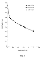
- Fig. 7 illustrates three consecutive polarization curves for this kind of fuel cell, under the following conditions: a solution of 1M MeOH and 3M H 2 SO 4 was circulated through the anode at a rate of 9 ml/min. Oxygen was circulated past the cathode at a pressure of 0.25 atm. over the atmospheric pressure. The cell temperature was 65°C. A 300 micron thick PCM consisting of (V/V) 16% nanosize powder of SiO 2 , 24% PVDF and 60% pore volume, of 1.5 nm typical diameter. The cell demonstrated over 100 hours of stable operation at 0.4V. After 100 hours of operation the current change was less then 3%.
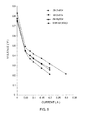
- Fig. 10 illustrates the polarization curves of these cells, operating with a solution of 1M MeOH in 3M sulfuric acid.
- Measurements of fuel crossover were carried out at several temperatures by feeding nitrogen instead of oxygen into the cathode compartment (at ambient pressure) and feeding organic fuel-acid solution into the anode compartment.
- Cell voltage was reversed; hydrogen was evolved at the fuel electrode while fuel that crossed over to the cathode side was oxidized.
- the current that flows at 1V was found to be the limiting current for fuel oxidation.
- Fig. 2 We engraved an Integrated Flow Field System into a graphite housing.
- the system is schematically described in Fig. 2 .
- the ratio of the electrolyte flow channels to gas flow channels is 1 : 2 and the maximum distance between adjacent electrolyte flow channels is 8 mm.
- the gas/electrolyte providing system is shown schematically in Fig 8 .
- Fig. 8 illustrates a H 2 /O 2 fuel cell 200 having a housing 210, an anode 220, a cathode 230 and a solid PCM 240.
- a hydrogen gas providing system 250 provides hydrogen to the fuel cell.
- An oxygen providing system 260 supplies oxygen either directly (as shown in Figure 8 ) or via the electrolyte tank 270 in order to achieve an equalization in pressures.
- the cell further comprises an oxygen purge system 280, an electrolyte pump 290 and a hydrogen purge system 300.
- the pump we used was a peristaltic pump and the electrolyte was 1.5 M sulfuric acid.
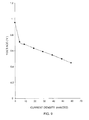
- Figure 9 shows a polarization curve for this fuel cell, at 1 PSI (over atmospheric pressure) hydrogen and oxygen pressure, at room temperature (about 25 °C).
- the electrolyte was circulated at 9 ml/min.
- the low fuel crossover enables the use of the fuel cell of the invention as a replacement for a primary battery.
- a fuel-acid solution is not circulated but is stored in the anode side (compartment) in a porous carbon matrix.
- the air inlet ports may be closed, for example, by adhesive tape when this fuel cell is not in use.
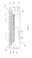
- FIG 11 illustrates schematically this kind of fuel cell, having 0.6mm thick Hastelloy C-276 TM end plates 300, porous non-woven carbon felt (or matrix) RVC 1000 TM (Carbone Lorraine) 310 which on one side serve as an air flow field and on the second side as storage cell for the fuel solution; Toray TM paper 320 and a Teflonated Toray TM paper 325 as backing layers, a PCM 330, air inlet ports 340, a fuel solution filling port 350, Teflon TM sealing rings 360, plastic envelopes made of shrinkable tube 370 for holding and sealing the whole assembly.
- nanosize Pt catalyst purchased from Johnson Matthey
- 5 mg nanosize Pt catalyst purchased from Johnson Matthey
- 5 mg of nanosize Pt-Ru 1:1 (atomic ratio) catalyst Johnson Matthey
- Both Toray papers were hot pressed to the PCM at 100°C and under a pressure of 40 kg./cm 2 for 200 sec.
- a cell was assembled having a fuel tank of thickness 4mm, located at the back side of the anode, and a PCM made of 10% silica, 30% PVDF and the balance voids, later filled with 3M H 2 SO 4 .
- a solution containing 3M H 2 SO 4 and 1M methanol was inserted through the fuel filling port 350 (closed by adhesive tape), and the cell was discharged.
- the open circuit voltage of the cell was 0.65V and it delivered 1mA/cm 2 for a few hours.
- the crossover current density was 2mA/cm 2 . This low crossover value allows the use of fuel solutions with concentrations of 1% to 40%, compared with 3% to 6% that are feasible with current art cells.
- FIG. 13 illustrates an orientation independent direct oxidation fuel cell system that makes use of several aspects of the present invention.
- the system 1000 comprises a fuel cell 1100, having an anode chamber 1110 with an anode 1112, a fuel inlet 1114 and a gas outlet 1116, a cathode chamber 1120 with a cathode 1122 and air inlet holes 1124, an electrolyte membrane 1200, preferably according to WO99/44245 and/or this invention, disposed between the anode 1112 and the cathode 1122, and a fuel tank 1300, which preferably is disposable, connected to the anode chamber 1110 through a (liquid) pipe line 1160 and a valve 1162.
- a fuel cell 1100 having an anode chamber 1110 with an anode 1112, a fuel inlet 1114 and a gas outlet 1116, a cathode chamber 1120 with a cathode 1122 and air inlet holes 1124, an electrolyte membrane 1200,
- the fuel tank 1300 is divided by a movable barrier 1310, into two parts: a first part 1312, which contains the fuel (either pure or in solution) and is connected to the anode chamber 1120, and a second part 1314, which optionally has a gas inlet 1316, by which gas may enter the second part 1314 to create there gas pressure of over one atmosphere. Alternatively, the gas pressure is provided by pressed gas stored permanently in the second part 1314.
- the barrier 1310 may be of any kind known in the art, such as a piston or a bladder. It is capable of directing fuel from the fuel tank 1300 to the anode chamber 1110 through the pipeline 1160 and valve 1162 irrespective of the orientation of the fuel cell system 1000.
- the gas outlet 1116 is closed with a gas permeable hydrophobic closure (not shown).
- the anode chamber 1110 and optionally the fuel tank 1300 are further equipped with fuel concentration sensors, 1111 and optionally 1320.
- the fuel concentration sensors 1111 and 1320 are connected to the controller 2000, which is capable of ordering streaming fuel from the fuel tank 1300 to the anode chamber 1110 through pipe line 1160 and valve 1162 in response to a fuel concentration that is under a predetermined value.
- the valve 1319 which is usually open to allow CO 2 escape into the atmosphere, should be closed.
- a DC to DC converter 1600 is connected to the fuel cell 1100 and possibly to one or more other fuel cells (not shown) connected in series with the fuel cell 1100 and the DC to DC converter 1600.
- the system is actually a hybrid power source in accordance with the invention, capable of charging a battery, such as the battery 1700 or supplying power to a portable appliance 1800.
- the second part of the fuel tank 1314 is full only with atmospheric air until operation, when it is filled through the gas inlet 1316 with CO 2 , evolving from the oxidation of the fuel at the anode chamber 1110.
- the CO 2 is brought from the anode chamber 1110 by pipeline 1150 and valve 1318 to the second part of the fuel tank 1114.
- the orientation independent fuel cell of Fig. 13 is preferably further equipped with a (preferably disposable) water tank 1500, which construction is similar to that of the fuel tank 1300.
- the water tank is needed in practice only in dry and hot environments, where water loss due to evaporation may require adding water to the system, or when pure fuel (and not a fuel solution) is used. Otherwise the fuel tank contains enough water for both the electrochemical reaction and the water loss due to evaporation.
Abstract
Description
- This invention relates to an electric cell that converts the chemical energy obtained in a fuel oxidation reaction directly into electric energy in a continuous process. More specifically the invention relates to fuel cells.
- Fuel cells are often described as continuously operating batteries or as electrochemical engines. Fuel cells utilize an external supply of fuel and oxygen (or air) and produce power continuously, as long as the fuel and oxygen supply is maintained.
- The most classic fuel cell is the H2/O2 fuel cell of the direct or indirect type, wherein hydrogen is oxidized to form H3O+ at the anode and oxygen is reduced to water at the cathode. In the direct type, hydrogen and oxygen are used as such, the fuel being produced in independent installations. The indirect type employs a hydrogen-generating unit, which can use as raw material a wide variety of fuels.
- Another type of fuel cell is the organic fuel cell. In a direct oxidation cell an aqueous solution of an organic fuel such as methanol, formaldehyde or formic acid, is directly fed into the fuel cell without any previous chemical modification, where the fuel gasket is oxidized at the anode, and oxygen is reduced to water at the cathode.
- A major distinguishing characteristic of different fuel cells is in the electrolyte used. NASA's Jet Prepulsion Laboratory (JPL) developed a direct liquid-feed cell using a solid membrane electrolyte. A detailed description of JPL's fuel cells can be found, for example, in
U.S. Patent Nos. 5,599,638 and5,773,162 . These fuel cells operate without any acid electrolyte and comprise solid electrolyte membranes fabricated from proton-exchange materials, especially Nafion™ (manufactured by DuPont). When methanol is used as the fuel, the electro-oxidation of methanol at the anode can be represented by:
CH3OH+H2O → CO2+6H+ + 6e,
and the electro-reduction of oxygen at the cathode can be represented by:
O2+4H+ + 4e → 2H2O.
Protons generated at the anode are transported directly across the electrolyte membrane to the cathode. A flow of current is sustained by a flow of ions through the cell and electrons through the external load. - The challenge in fuel cell development for practical applications is to improve the economics through the use of low-cost components with acceptable life and performance.
Thus, the present invention provides by the first of its aspects a fuel cell comprising an anode chamber including an anode and means for providing fuel to the anode, a cathode chamber including a cathode and means for providing oxygen to the cathode, and a solid electrolyte membrane disposed between said cathode and said anode, wherein said solid electrolyte membrane is a proton conducting membrane having pores with a diameter, smaller than 30 nm, said membrane comprising: - (i) 5% to 60% by volume, preferably 8% to 30% by volume of an electrically nonconductive inorganic powder having a good acid absorption capacity, said powder comprising nanosize particles;
- (ii) 10% to 90% by volume, preferably 30% to 80% by volume of an acid or aqueous acid solution; and
- (iii) 5% to 50% by volume, preferably 12% to 40% by volume of a polymeric binder that is chemically compatible with said acid, oxygen and said fuel.
- (a) operating the cell at a reversed voltage of 0.6 to 1.3V for a period of time T.
- Preferably, the time period T is between 1 to 100 minutes. A longer period T is preferable as the cell ages or as it suffers a higher level of impurities.
Preferably, the voltage is between 0.6 and 1.3V.
The inventors applied thisreconditioning procedure 10 times, each time for 1 to 30 minutes, during a 3500 hours operating period of a fuel cell and found an improvement of the cell voltage of 50 to 100mV.
The invention also provides a method for preparing a catalyst layer for use in a fuel cell, said method comprising the steps of forming up to one monolayer of a catalyst on the surface of a nanosize inorganic powder, such monolayer serving as a nucleation site, forming additional one or more catalyst layers on the top of said first monolayer to obtain catalyst particles and subsequently binding the obtained particles to the carbon backing layer and/or to the proton conducting membrane.
According to another aspect of the present invention there is provided a hybrid power source comprising a liquid feed fuel cell according to the invention, a DC to DC converter and a rechargeable battery.
According to another aspect of the present invention there is provided a device for controlling the water return flow from the cathode side to the anode side in a fuel cell, comprising a water or fuel solution level sensor and air or oxygen pressure control unit placed in the cathode compartment, and a fuel cell comprising such a device.
According to another aspect of the present invention there is provided a method for reducing crossover current in a fuel cell having an anode chamber with an anode and a fuel tank for providing said anode with fuel, a cathode chamber with a cathode and means for providing said cathode with oxygen in a given pressure, a solid electrolyte membrane disposed between said cathode and said anode, and a tank for water or fuel solution, an air or oxygen pressure control unit and a sensor for sensing the level fuel solution in said fuel tank and means for controlling said pressure in response to said level of water or fuel, comprising the steps of: - (One) sensing the level of the water or fuel in the water or fuel tank;
- (Two) controlling the air or oxygen gas pressure in the cathode chamber to increase as the level of water or fuel solution sensed in step (a) decreases;
- thus reducing the crossover current.
- According to another aspect of the present invention there is provided a free direct oxidation fuel cell having a low crossover current density, wherein the fuel solution tank is directly attached to the anode chamber, the fuel concentration is between 1% and 40% (w/w) and the ratio between the tank volume (in ml) and the electrode area, in cm2 is between 3:1 and 30:1.
- According to another aspect of the present invention there is provided an orientation independent direct oxidation fuel cell system having
- (One) an anode chamber with an anode, fuel inlet and gas outlet;
- (Two) a cathode chamber with a cathode and oxygen or air inlet;
- (Three) an electrolyte membrane disposed between the anode and the cathode; and
- (Four) a fuel tank connected to the anode chamber,
wherein- a) said fuel tank being divided by a movable barrier into two parts, said first part of the fuel tank being capable of containing fuel or fuel solution and connected to the anode chamber, said second part of the fuel tank holding gas with pressure greater than atmospheric pressure or having a closable gas inlet;
- b) said gas outlet being closed with a gas permeable hydrophobic matrix;
- said barrier being capable of directing fuel or fuel solution from the fuel tank to the anode chamber irrespective of the fuel cell orientation.
- In order to understand the invention and to see how it may be carried out in practice, several embodiments will now be described, by way of non-limiting example only, with reference to the accompanying drawings, in which:
-
Fig. 1 shows a schematic representation of a multi-cell fuel system. -
Fig. 2 shows an integrated gas - acid solution flow field system used in a hydrogen/oxygen fuel cell. -
Fig. 3 shows a graph illustrating polarization curves at different methanol concentrations. -
Fig. 4 shows a graph illustrating polarization curves for different acids. -
Fig. 5 shows a graph illustrating the effect of additives on polarization curves. -
Fig. 6 shows a graph illustrating the relation between the pore size of PCMs and temperature of hot press -
Fig. 7 shows a graph illustrating three consecutive polarization curves (3M H2SO4 + 1M MeOH at 65°C.). -
Fig. 8 shows a schematic representation of a H2/O2 fuel cell with integrated gas-acid flow field. -
Fig. 9 shows a graph illustrating a polarization curve for a H2/O2 fuel cell (25°C, 1psi H2 and O2 pressure). -
Fig. 10 shows a graph illustrating the polarization curve of a cell operating with a solution of 1M MeOH in 3M sulfuric acid. -
Fig. 11 shows a schematic representation of a fuel cell which operates as a primary battery. -
Fig. 12 provides a schematic representation of an improved solid feed organic fuel cell having a solid polymeric membrane configured in accordance with a preferred embodiment of the invention. -
Fig. 13 is a schematic illustration of an orientation independent hybrid power source according to one embodiment of the present invention. - Several embodiments of the invention will be described and exemplified with reference to the figures.
- According to one aspect of the present invention there is provided an improved fuel cell. The fuel cell to be improved by the invention includes an anode chamber including an anode and means for providing fuel to the anode, a cathode chamber including a cathode and means for providing oxygen to the cathode, and a solid electrolyte membrane disposed between said cathode and said anode. Such fuel cells and their way of operation are well known in the art. The present invention seeks to improve prior art fuel cells by applying as an electrolyte membrane a proton conducting membrane having pores with a diameter, smaller than 30 nm, said membrane comprising:
- (i) 5% to 60% by volume, preferably 8% to 30% by volume of an electrically nonconductive inorganic powder having a good acid absorption capacity, said powder comprising nanosize particles;
- (ii) 10% to 90% by volume, preferably 30% to 80% by volume of an acid or aqueous acid solution; and
- (iii) 5% to 50% by volume, preferably 12% to 40% by volume of a polymeric binder that is chemically compatible with said acid, oxygen and said fuel.
- The anode, the cathode and the solid electrolyte membrane are typically hot pressed so as to form a single structure unit. The fuel used by the cell may be, for example, a pure organic liquid fuel, an aqueous solution of an organic fuel, a water solution comprising an acid and an organic fuel, or a gas. A large variety of low vapor pressure acids that are compatible with the cell hardware and with the catalysts at both electrodes may be used in the acid-fuel solution. Non-limiting examples for such acids are: alkyl sulfonic acids, polyfluoroolefin sulfonic acid, perfluoroolefin sulfonic acid, aryl sulfonic acids, polyfluoroaryl sulfonic acids, such as polyfluorobenzen, polyfluorotoluene, or polyfluorostyrene sulfonic acid, perfluoroaryl sulfonic acids, such as perfluorobenzene, perfluorotoluene or perfluorostyrene sulfonic acid, and similar acids where up to 50% of the hydrogen or fluorine atoms were replaced by chlorine atoms, CH3CH2SO3H, benzyl sulfonic acid, CF3(CF2)nSO3H, HO3S(CF2CH2)nSO3H, CF3(CF2CH2)nSO3H, HO3S(CF2)nSO3H where n is an integer having a value of 0 to 9, Nafion™ ionomers, phosphoric acid, sulfuric acid, sulfamic acid and mixtures thereof.
- To the acid-fuel solution it is possible to add, according to the present invention, a soluble catalyst such as a macrocyclic complex of nickel, cobalt or iron. Such a complex may promote the oxidation of the fuel and/or the reduction of the oxygen. The solid electrolyte membrane is a proton conducting membrane (PCM) having pores with a typical diameter smaller than 30nm, preferably smaller than 3 nm, more preferably smaller than 1.5 nm. The membrane comprises inorganic powder of nanosize particles, an acid or aqueous acid solution, and a polymeric binder. The inorganic powder is electrically nonconductive, it has a good acid absorption capacity, and it constitutes 5% to 60%, preferably 8% to 30%, of the membrane volume. The acid or aqueous acid solution constitutes 10% to 90%, preferably 30% to 80% of the membrane volume. The acid of the
membrane 6 is that of the fuel-acid solution. The polymeric binder constitutes 5-50% preferably 12 to 40% of the membrane and is chemically compatible with the acid of the membrane, with oxygen and with the fuel used in the cell. - It is shown in detail hereinbelow, that in comparison to current-art Nafion™ membranes, the PCMs used in the fuel cell of the present invention have a better conductivity and lower crossover for methanol or other fuels. It is also shown that the PCMs of the invention have the advantages over the Nafion™ PCM in not being affected by heavy metal impurities and in being operable at temperatures higher than 100°C or lower than 0°C. Furthermore, the cost of the PCMs of the invention is lower than that of Nafion™ by about two orders of magnitude, thus lowering the price of the entire fuel cell.
The invention further provides the following improvement in fuel cells: - Improving the efficiency of a fuel cell
- In this section we describe several techniques for improving the efficiency of fuel cells. These techniques were invented during the investigation of the fuel cell of the invention, however, some of them may also be applied for improving current-art fuel cells.
- As known in the art, one of the factors that reduce fuel cells efficiency is fuel crossover, i.e. the undesired permeation of the fuel molecules through the electrolyte membrane to the cathode chamber, thus lowering the operating potential of the fuel cell. The rate of crossover is known to be proportional to the permeability of the fuel through the solid electrolyte membrane and to increase with increasing concentration and temperature.
- The inventors found that the use of the fuel cell of the invention with pores smaller than 1.5nm is one way to reduce the crossover current. For example, the crossover current density for a Nafion™ 117 membrane (that have pores of 3-4nm), in 1M methanol at 60 °C is 140 mA/cm2, while that of the PCM used in the present invention (having pore size of less than 1.5nm) is 18.5-25 mA/cm2, at 65°C and 31.8 mA/cm2 at 75°C.
- Furthermore, it has been found by the present inventors that the permeability of the solid electrolyte membrane to the liquid fuel can be further reduced with minor effect on the conductivity, by changing the membrane properties such as pore size diameter and pore's neck diameter. Such a change may be achieved by filling these pores with proton conducting materials or by adding salts to the fuel acid solution. Therefore, in a preferred embodiment of the present invention the solid electrolyte membrane has pores that are partially filled with proton conducting materials. Another preferred embodiment of the present invention has a solid electrolyte membrane which further comprises salts. Other PCMs, such as Nafion™ may also benefit from partially filling their pores with proton conductive materials. In addition, it has been found that fuel crossover may be further reduced by filling the pores of the PCM with a Na2SiO3 solution and hydrolyzing the silicate in sulfuric acid to form in the pores nano particles of hydrated silica or silicic acid. Alternatively, this effect can also be achieved by filling the pores with a polyhetroacid such as H3PW12O40 or H4SiW12O40 and preferably hot pressing the PCM so as to reduce the size of the pore's neck and to lock the acid in the pores.
- Fuel crossover may also be reduced by lowering the concentration of the fuel or by choosing a fuel having a molecular size larger than that of methanol, thus having a smaller diffusion coefficient. Examples of such known fuels are, methylformat, ethylformat, dimethoxymethane, trimethoxymethane and trioxane.
- It has been found that the crossover of methanol in the fuel cell of the invention may be further reduced, by adding to the acidic fuel solution salts such as soluble organic sulfonates, for example: potassium benzene sulfonate, or the sulfates of zinc, aluminum, potassium, sodium, cobalt, manganese, nickel, cesium, or magnesium preferably in the form of hydrates. Typical amounts of salts to be added are such as to provide an acid to salt molar ratio of between 1:10 and 10:1. Preferable salts are those wherein both cation and anion are not susceptible to electrochemical reactions, such as sulfates of alkaly metals, alkaline earth metals, zinc and aluminum. Other considerations in selecting a salt to be used according to this aspect of the present invention is that preferable salts should be compatible with oxygen, with the catalysts and with the fuel and should not form electronically conductive residues when dry. They preferably have high dehydration temperatures, indicating a strong bonding of water. Examples for such hydrates and their decomposition temperatures (in brackets) are ZnSO4•7H2O (280°C), Al2(SO4)3•18H2O (86°C), MgSO4•7H2O (150°C), NiSO4, CoSO4•7H2O (96.8°C), MnSO4•7H2O (280°C). Alkali sulfates such as Cs2SO4 and Na2SO4 have high solubility and reduce the water vapor pressure. Thus, enabling the use of the fuel cell at low pressures above 100°C. Ammonium sulfate has high solubility but it may decompose slowly, therefore, it may also be useful at low temperatures. Another advantage in adding salts to the fuel solution is that some of them may function at elevated temperatures as molten hydrates and reduce the water vapor pressure, thus allowing for the operation of the fuel cell at temperatures higher than 100°C. Operating at such elevated temperatures may be advantageous, since at these temperatures steam may be produced to allow cogeneration of heat and electricity, and to lead to a higher energy conversion efficiency. In addition, at high temperature of operation the fuel cell can tolerate higher concentrations of CO and smaller amounts of expensive catalyst is needed. Notably, apart of the salts added to the fuels, it is also the acid contained in the fuel solution which helps fuel cells which make use of acidic fuel solution to operate in temperatures wherein water is not liquid. For instance, a 27% H2SO4 solution freezes at -27°C.
- As mentioned above, the PCM used in the fuel cells of the invention is not affected by heavy metal impurities, while Nafion is very sensitive to heavy metals impurities. For example, 500 ppm chromium reduced the conductivity of a Nafion based membrane by a factor of eight from 0.1 S/cm to 0.013 S/cm (Warthesen and Shores Extended Abstract Vol. 33rd). The same concentration of iron, which has similar effect on conductivity as chromium, did not significantly affect the conductivity of the PCM used in the invention. The tested PCM consisted of (V/V) 24% PVDF (polyvinilyden fluoride) as a binder, 16% SiO2 as an inorganic nanopowder and 60% 3M sulfuric acid. The conductivity measured without iron impurities was 0.18 S/cm, while that measured in the presence of 500 ppm iron sulfate was 0.17 S/cm. This feature of the PCM used in the invention is very important and unique as it enables the use of catalysts consisting of non noble metals or Pt alloys with non-noble metals (M) such as Fe, Ni or Co. It was found that Pt-M alloys are much better catalysts for oxygen reduction, and the preferred ratio Pt-M is between 1:3 to 3:1. These results also make possible the use of metals like super alloys and low corrosion stainless steel alloys for the fuel cell hardware and for peripheral subsystems with smaller risk of affecting the conductivity of the membrane.
- The catalyst used for the air (oxygen) cathode is commonly nano particles (preferably 2-5 nm) of Pt or Pt alloys where the one used at the methanol anode is a Pt - Ru alloy of nano size (preferably 5 - 10 nm ) particles. However, in order to save the cost of expensive noble metals, it is possible to use non noble metal based alloys such as for example Ni, Fe or Co and coat them with the required noble metal catalyst by common electrochemical or chemical processes. The thickness of such catalyst layer may be between less than one monolayer to 20 monolayers.
- After long operation periods, the bond between the catalyst particles and the supporting carbon matrix is lost leading to the degradation of the fuel cell. In view of that it is proposed in the present invention to bind the nano size catalyst to a nano size ceramic powder and subsequently bind the obtained particles to the carbon backing layer and to the PCM. A good way to perform this is to use the well-known commercially available electroless process. According to this process, up to one monolayer of a catalyst salt (like PtCl4, RuCl3, etc.) is adsorbed in the first step on nano size hydrated silica powder by immersing the powder in a solution containing a predetermined amount of the catalyst salt. Then, in the second step, a proper amount of a reducing agent like formaldehyde, methanol, formic acid or hypophosphite is added at a suitable pH and temperature to form up to one monolayer of catalyst bonded to the surface of the ceramic powder. This monolayer provides nucleation sites for further deposition. Next, one or several catalyst salts and more reducing agents are added to form the final size of the catalyst particles. For a methanol anode it is preferred to form either a Pt-Ru alloy catalyst layer or to form two consecutive layers of Pt on Ru or Ru on Pt with atomic ratio of 1:10 to 10: 1. Other elements, like Sn, Os, Ni can be added to the catalyst layer to further improve the kinetics of fuel oxidation. In the same way catalyst layers consisting of Pt or Pt nano size alloys with Co, Ni, Fe, or Ag can be prepared for the oxygen cathode.
- The present invention also provides an improvement in hydrogen/oxygen fuel cells, which use a PCM according to
WO 99/44245 Fig. 2 ) was designed in order to prevent changes in electrolyte concentration during fuel cell operation. In this system two integrated sets offlow channels - When preparing the integrated flow field system in the housing of the fuel cell, the maximum allowed distance between adjacent electrolyte and gas flow channels would usually be a factor of the membrane capillary forces. The ratio of electrolyte flow channels to gas flow channels will usually be determined by individual system optimization and by comparing the need to supply electrolyte versus the need to supply reactant gasses.
- In
Figure 2 an integrated flow system is shown schematically. Through the channel 100 a reactant gas, i.e. hydrogen, (entrance at 1A and exit at 1B) flows, while through thechannel 110 the electrolyte (entrance at 2A and exit at 2B) is circulated. In the flow system shown schematically inFig. 2 the ratio of electrolyte flow channels to gas flow channels is 1: 2 and the maximum distance between adjacent electrolyte flow channel and gas channel is 8 mm. - The integrated flow field system of the invention can be formed either on the anode side or on the cathode side or on both sides.
- The integrated flow field system can also be used as a part of the temperature control system, or as a part of the water removal system (by controlling water vapor pressure via temperature gradient).
- Direct methanol fuel cell (DMFC) and liquid feed fuel cells (LFFC) are low power sources. However, devices like cellular telephones, computers and small electric vehicles need high power for short times. For these and for similar applications it is possible to combine a fuel cell according to the invention with a small high power rechargeable battery, which supplies the high power when required. Such a combination is advantageous over current art hybrid power source, inter alia thanks to the small crossover current. Today DC to DC converters can start working from 0.7V. As a result it is possible to combine as few as two or three fuel cells (in a series combination) through a DC to DC converter to a battery. If the crossover current density is small enough, say 15 preferably 5mA/cm2 or less, such a hybrid power source need not be fueled very often. Therefore, this hybrid power source is preferably with a fuel cell of low crossover current such as the fuel cell of the invention. The fuel cell charges the battery and supplies the low power demand while the high power battery supplies the heavy loads. This small number of required fuel cells enables the use of a flat and thin fuel cell system.
- For example, to power a cellular phone it is possible to use a hybrid power source built of two thin methanol fuel cells, connected in a series combination, a DC to DC converter and a small high power lithium ion cell.
- In any fuel cell based on a proton conducting membrane the protons that cross through the proton conducting membrane carry with them about three water molecules per proton. In a DMFC six protons move through the membrane for each methanol molecule. It means that 18 water molecules are carried out by the protons per each methanol molecule that was oxidized.
- This phenomenon causes a significant loss of water. Usually, in order to minimize water loss, the water from the exhaust of the fuel cell are collected and recycled. A new way to minimize water loss is suggested here. It was found that the application of excess pressure in the cathode compartment causes a decrease in the methanol crossover. Each 0.1 atmospheres excess gas pressure causes a decrease of about 10% in the crossover current (for example, at 1M methanol and at 60 degree C it decreases by 7 mA/cm2, from 70 mA/cm2 to 63 mA/cm2). This is explained by hydraulic stream of the fuel solution from the cathode side to the anode side. As the water methanol ratio is about 53:1, the back stream of water by this effect is equivalent to 7x53 or 371 mA/cm2, or to a water flux of 0.371x 10⁻⁶ moles per sec.cm2. This effect can be utilized as water return mechanism in any fuel cell comprising a proton conducting membrane. At steady state the protons current equals the external load electronic current and the water flux carried out by the protons is three times larger. As a result at a load of 100mA/cm2 the water flux is equivalent to 300 mA/cm2 and an excess pressure of 0.1 atmospheres may be enough to return the water back from the cathode side to the anode side. A water (or fuel solution) level sensor can be installed in the water (or fuel solution) tank and the air or oxygen pressure at the cathode compartment will be controlled to keep this water (or fuel solution) level constant.
- Such a device was found by the inventors to reduce the crossover current. It is therefore provided by the present invention a device comprising a solution level sensor and a gas pressure control unit; said gas pressure control unit being capable to control the gas pressure in response to the solution level as sensed by the sensor. In particular the invention provides a fuel cell having an anode chamber with an anode and means for providing the anode with fuel, a cathode chamber with a cathode and means for providing the cathode with oxygen in a given pressure, a tank for water or fuel solution, an air or oxygen pressure control unit and a sensor for sensing the level of the water or fuel solution in said tank and means for controlling said pressure in response to said level of water or fuel, and a method for reducing crossover current in such a fuel cell, comprising the steps of:
- (One) sensing the level of the water or fuel solution in the water or fuel solution tank;
- (Two) controlling the air or oxygen gas pressure in the cathode chamber to increase as the level of water or fuel solution sensed in step (a) decreases;
- thus reducing the crossover current.
- The present invention also provides, according to another of its aspects, for a direct oxidation fuel cell, which has no pumps. The pump and valves of current art fuel cells, which are not needed any more according to this aspect of the invention, are used to deliver fuel from a fuel reservoir to the anode chamber. This delivery is needed because current art crossover levels are such that necessitate large fuel reservoirs (due to large quantities of fuels that are spent on crossover). The present invention thus provides for a pump free direct oxidation fuel cell, wherein the fuel tank is directly attached to the back side of the anode (the opposite side to the PCM), as, for instance illustrated in Example 5, bellow. In order for such a cell to be of practical use, it should have a low crossover current, typically 15mA/cm2 or less, preferably 5mA/cm2 or less, more preferably 2mA/cm2 or less. Otherwise, the fuel tank should be non-practically large, or the lifetime of the cell becomes inconceivably short. The required low crossover current may be achieved by applying a PCM of the kind described in
WO99/44245 - At room temperature, the crossover current density measured in a fuel cell according to this aspect of the invention provided with 3% methanol, was less than 5mA/cm2. A 25cm2 cell can supply between 300 to 600mA and has a crossover of 125mA (under no load conditions). When a tank of 300 ml acidic fuel solution is attached to such a pump free DOFC it contains (3
% X 300 ml =) 9gr methanol, which may produce 45Ah. These 45Ah may be consumed by the crossover for 720 hours. Under these conditions a few grams of methanol should be added to the fuel tank once a week, making it a very convenient power source. - Typically, two or three such cells are used in combination with a DC to DC converter to give a hybrid power source as described above. Such a hybrid power source may be conveniently used as a battery charger for cellular phones and other small appliances. For a practical, pump free DOFC having a PCM with crossover current density of between 1.5mA/cm2 to 15mA/cm2. The ratio between the fuel tank volume (in ml) and the electrode area (in cm2) should preferably be between 1:3 to 1:230.
- When a fuel cell is used in a portable device, such as cellular phone, it should be designed to be orientation independent, so that fuel reaches the cell from the fuel tank irrespective of the cell orientation. Thus, the present invention provides, according to another of its aspects, an orientation independent direct oxidation fuel cell, having an anode chamber with an anode, fuel inlet and gas outlet, said gas outlet being closed with a gas permeable hydrophobic matrix; a cathode chamber with a cathode and oxygen inlet; an electrolyte membrane disposed between the anode and the cathode; and a fuel tank connected to the anode chamber, wherein said fuel tank being divided by a movable barrier into two parts and; said first part of the fuel tank being capable of containing fuel and is connected to the anode chamber, said second part of the fuel tank having a closable gas inlet, and said barrier being capable of directing fuel from the fuel tank to the anode chamber irrespective of the fuel cell orientation.
- Usually, said second part of the fuel tank is full with gas at a pressure that is higher than atmospheric pressure so that the gas is capable of pushing the barrier to direct fuel out of the fuel tank into the anode chamber. Alternatively, the second part of the fuel tank is full only with atmospheric air until operation, when it is filled through the gas inlet with CO2, evolving from the oxidation of the fuel at the anode chamber.
- Such an orientation independent fuel cell is also pump free and require only a small number of valves.
- The invention will be further described in more detail in the following non-limiting examples.
- A fuel cell housing was fabricated from synthetic graphite plates purchased from Globetech Inc., in which a flow field was engraved.
The anode was formed using a platinum-ruthenium ink that was spread on a carbon fiber sheet commercially available from Toray TM paper. Several types of inks were prepared, as follows: - 1. Type A was prepared by mixing 600 mg of 60% Pt:Ru on Vulcan XC-72 (purchased from E-Tek Inc), 60 mg Kynar 2801 PVDF, 0.26 ml propylene carbonate (PC) and about 1.5 ml of cyclopentanon;
- 2. Type B was prepared by mixing 600 mg of 20% Pt/ 10% Ru/ Vulcan C-72 (purchased from ElectroChem, Inc), 60 mg Kynar 2801 PVDF, 0.38 ml propylene carbonate (PC) and about 1.5 ml of cyclopentanon;
- 3. Type C was prepared by mixing 600 mg of 20% Pt/ 10% Ru/ Vulcan XC-72 (purchased from ElectroChem, Inc), 60 mg Kynar 2801 PVDF, 60 mg Aerosil 130 (purchased from Degussa AG), 0.42 ml propylene carbonate (PC) and about 1.5 ml of cyclopentanon.
- A second cell configuration was manufactured by painting the anode side flow field and both sides of the anode Toray TM paper with Pt:Ru ink. This modification was made in order to increase the catalyst content per square cm.
- The crossover was measured by two test methods:
- 1. Using the regular configuration of the fuel cell but using nitrogen instead of oxygen at the anode and methanol in 3M H2SO4 at the cathode. The current (at 1V) measured is a product of the oxidation of the methanol that penetrated through the PCM from the cathode to the anode side.
- 2. The same as in
Method 1 above but both electrodes were painted with Pt-Ru ink and the crossover current was calculated in the same way as in 1. - In order to improve performance, another methanol fuel cell was manufactured with the use of pure metal catalysts, instead of carbon supported catalysts. A cathodic catalyst ink was prepared by the following process:
- A nano powder Pt (Pt black, purchased from "Johnson Matthey"), Teflon ™ emulsion and
Nafion ™ 5% solution were combined in the following weight proportions: 60%Pt, 25% Teflon emulsion and 15% Nafion. First the Pt powder and the Teflon emulsion were mixed by sonication for 15 minutes. After two sonication periods, the ink obtained was placed on a magnetic stirrer for at least one night. - An anodic catalyst ink was prepared by the following process: A Pt:Ru nano powder (Pt:Ru black 50% purchased from "Johnson Matthey") and PVDF were mixed in the following weight proportions: 91 % catalyst powder and 9% PVDF. Propylene carbonate was added in an amount equal to 30-70% of the catalyst volume, then cyclopentanone was added and the ink obtained was stirred for at least one night.
- Preparation of the electrodes: the cathode catalyst ink was applied on teflonated Toray™ carbon fiber paper, to form 4 mg Pt/cm2. The ink (in the form of a paste) was spread in layers, allowing each layer to dry for about one hour, before the next layer was applied. This operation was repeated until the desired amount of catalyst was obtained. In the same way, the anode catalyst ink was applied on unteflonated Toray™ carbon fiber paper, until 5-10 mg catalyst/cm2 was obtained. Both electrodes were washed with 3M sulfuric acid and then with water.
- The cathode was hot pressed under a pressure of 10-70 Kg/cm2, at a temperature of 85-130°C to one side of a PCM with a thickness of 100-300 µm. The anode was placed on the other side of the PCM, parallel to the cathode and the complete cell was assembled.
-
Fig. 7 illustrates three consecutive polarization curves for this kind of fuel cell, under the following conditions: a solution of 1M MeOH and 3M H2SO4 was circulated through the anode at a rate of 9 ml/min. Oxygen was circulated past the cathode at a pressure of 0.25 atm. over the atmospheric pressure. The cell temperature was 65°C. A 300 micron thick PCM consisting of (V/V) 16% nanosize powder of SiO2, 24% PVDF and 60% pore volume, of 1.5 nm typical diameter. The cell demonstrated over 100 hours of stable operation at 0.4V. After 100 hours of operation the current change was less then 3%. - Other cells were built according to the same procedure described above, but using another cathode ink. This cathode ink consisted of (weight %) 0-5% nanosize SiO2, 20-40% Teflon and 40-80% nanosize Pt powder.
Fig. 10 illustrates the polarization curves of these cells, operating with a solution of 1M MeOH in 3M sulfuric acid. - Measurements of fuel crossover were carried out at several temperatures by feeding nitrogen instead of oxygen into the cathode compartment (at ambient pressure) and feeding organic fuel-acid solution into the anode compartment. Cell voltage was reversed; hydrogen was evolved at the fuel electrode while fuel that crossed over to the cathode side was oxidized. The current that flows at 1V was found to be the limiting current for fuel oxidation.
- We engraved an Integrated Flow Field System into a graphite housing. The system is schematically described in
Fig. 2 . In this system the ratio of the electrolyte flow channels to gas flow channels is 1 : 2 and the maximum distance between adjacent electrolyte flow channels is 8 mm. We have fabricated a fuel cell system with an Integrated Flow Field System at the anode side. We then attached the fuel cell to gas providing systems that combined with an electrolyte circulating system. This system is built in such a way that the hydrogen and the electrolyte pressures at the Integrated Flow Field System are equal. The gas/electrolyte providing system is shown schematically inFig 8 . -
Fig. 8 illustrates a H2/O2 fuel cell 200 having ahousing 210, ananode 220, acathode 230 and asolid PCM 240. A hydrogengas providing system 250 provides hydrogen to the fuel cell. Anoxygen providing system 260 supplies oxygen either directly (as shown inFigure 8 ) or via theelectrolyte tank 270 in order to achieve an equalization in pressures. The cell further comprises anoxygen purge system 280, anelectrolyte pump 290 and ahydrogen purge system 300. The pump we used was a peristaltic pump and the electrolyte was 1.5 M sulfuric acid. -
Figure 9 shows a polarization curve for this fuel cell, at 1 PSI (over atmospheric pressure) hydrogen and oxygen pressure, at room temperature (about 25 °C). The electrolyte was circulated at 9 ml/min. - The low fuel crossover enables the use of the fuel cell of the invention as a replacement for a primary battery. In this case, a fuel-acid solution is not circulated but is stored in the anode side (compartment) in a porous carbon matrix. The air inlet ports may be closed, for example, by adhesive tape when this fuel cell is not in use.
-
Figure 11 illustrates schematically this kind of fuel cell, having 0.6mm thick Hastelloy C-276™end plates 300, porous non-woven carbon felt (or matrix) RVC 1000™ (Carbone Lorraine) 310 which on one side serve as an air flow field and on the second side as storage cell for the fuel solution; Toray™ paper 320 and a Teflonated Toray™ paper 325 as backing layers, aPCM 330,air inlet ports 340, a fuelsolution filling port 350, Teflon ™ sealing rings 360, plastic envelopes made ofshrinkable tube 370 for holding and sealing the whole assembly. On the cathode side of the PCM, 5 mg nanosize Pt catalyst (purchased from Johnson Matthey) was spread following the procedure described in Example 3, on theteflonated Toray paper 325 to form a catalyst layer 380 while on the anode side, 5 mg of nanosize Pt-Ru 1:1 (atomic ratio) catalyst (Johnson Matthey) was spread following the procedure described in Example 3, on Toray ™ paper 320 to form a catalyst layer 390. Both Toray papers (after applying the catalysts) were hot pressed to the PCM at 100°C and under a pressure of 40 kg./cm2 for 200 sec. After cell assembly, a solution containing 1 M H2SO4 and 0.5M methanol was inserted through the fuel filling port 350 (closed by adhesive tape), and the cell was discharged. The open circuit voltage of the cell was 0.5V, and it delivered 1mA/cm2 for a few minutes. - In another experiment, a cell was assembled having a fuel tank of thickness 4mm, located at the back side of the anode, and a PCM made of 10% silica, 30% PVDF and the balance voids, later filled with 3M H2SO4. After cell assembly a solution containing 3M H2SO4 and 1M methanol was inserted through the fuel filling port 350 (closed by adhesive tape), and the cell was discharged. The open circuit voltage of the cell was 0.65V and it delivered 1mA/cm2 for a few hours. The crossover current density was 2mA/cm2. This low crossover value allows the use of fuel solutions with concentrations of 1% to 40%, compared with 3% to 6% that are feasible with current art cells.
-
Figure 13 illustrates an orientation independent direct oxidation fuel cell system that makes use of several aspects of the present invention. Thesystem 1000 comprises afuel cell 1100, having ananode chamber 1110 with ananode 1112, afuel inlet 1114 and agas outlet 1116, acathode chamber 1120 with acathode 1122 and air inlet holes 1124, anelectrolyte membrane 1200, preferably according toWO99/44245 anode 1112 and thecathode 1122, and afuel tank 1300, which preferably is disposable, connected to theanode chamber 1110 through a (liquid)pipe line 1160 and avalve 1162. Thefuel tank 1300 is divided by amovable barrier 1310, into two parts: afirst part 1312, which contains the fuel (either pure or in solution) and is connected to theanode chamber 1120, and asecond part 1314, which optionally has agas inlet 1316, by which gas may enter thesecond part 1314 to create there gas pressure of over one atmosphere. Alternatively, the gas pressure is provided by pressed gas stored permanently in thesecond part 1314. Thebarrier 1310 may be of any kind known in the art, such as a piston or a bladder. It is capable of directing fuel from thefuel tank 1300 to theanode chamber 1110 through thepipeline 1160 andvalve 1162 irrespective of the orientation of thefuel cell system 1000. Thegas outlet 1116 is closed with a gas permeable hydrophobic closure (not shown). Theanode chamber 1110 and optionally thefuel tank 1300 are further equipped with fuel concentration sensors, 1111 and optionally 1320. Thefuel concentration sensors 1111 and 1320 are connected to thecontroller 2000, which is capable of ordering streaming fuel from thefuel tank 1300 to theanode chamber 1110 throughpipe line 1160 andvalve 1162 in response to a fuel concentration that is under a predetermined value. In such occasions, thevalve 1319, which is usually open to allow CO2 escape into the atmosphere, should be closed. - A DC to
DC converter 1600 is connected to thefuel cell 1100 and possibly to one or more other fuel cells (not shown) connected in series with thefuel cell 1100 and the DC toDC converter 1600. Thus, the system is actually a hybrid power source in accordance with the invention, capable of charging a battery, such as thebattery 1700 or supplying power to aportable appliance 1800. - In the embodiment of
Fig. 13 , the second part of thefuel tank 1314 is full only with atmospheric air until operation, when it is filled through thegas inlet 1316 with CO2, evolving from the oxidation of the fuel at theanode chamber 1110. The CO2 is brought from theanode chamber 1110 bypipeline 1150 andvalve 1318 to the second part of thefuel tank 1114. - The orientation independent fuel cell of
Fig. 13 is preferably further equipped with a (preferably disposable)water tank 1500, which construction is similar to that of thefuel tank 1300. The water tank is needed in practice only in dry and hot environments, where water loss due to evaporation may require adding water to the system, or when pure fuel (and not a fuel solution) is used. Otherwise the fuel tank contains enough water for both the electrochemical reaction and the water loss due to evaporation.
The solid proton conducting membrane used in the fuel cells of the present invention has been described in
The inorganic nanosize powder used for preparing the solid proton conducting membrane may be selected from the group consisting of SiO2, ZrO2 B2O TiO2 Al2O3, hydroxides and oxy- hydroxydes of Ti, Al, B and Zr, and any combinations thereof.
As described above, the proton conducting membrane used in the fuel cell of the invention comprises, inter alia, an acid. Typically, the diameter of the membrane pores is smaller than 30nm, preferably smaller than 3 nm, more preferably smaller than 1.5 nm. As opposed to the solid electrolyte membrane described for example in
Thus, such a PCM comprises a matrix made of silica powder, preferably nanopowder, bonded with an appropriate polymer binder described above, and acid molecules chemically bonded to the silica, thus reducing or avoiding the need to insert acid into the fuel solution. Other nanopowders can be used in a similar way. According to this option the acid, preferably sulfonic acid, is chemically bonded to the inorganic nanopowder directly or through an organic segment R selected from -(CH2)n-, -(CF2)n-, -(CF2CH2)m-, where n is an integer from 1 to 10 and m is an integer from 1 to 5, perfluoroaryl, polyfluoroaryl, perfluorostyrene, polyflouro styrene and similar segments where up to 50% of the hydrogen or fluorine atoms were replaced by chlorine atoms.
A non limiting procedure to form sulfonic acid groups bonded to silica is described hereinbelow: nano size silica powder is boiled in pure water for two hours to enrich the powder surface with OH groups. Than the hydrated powder is immersed in a solution of cloro, methoxy, or alkoxy organo sulfur silan of the type CH3COSR-Si(OCH3)3 or CH3COSR-SiCl3, where R is one of the organic segments listed above. The silan reacts with the surface OH groups of the silica powder to form up to one monolayer of the organic sulfur silan. Than the powder is oxidized by air and the thioacetat group is converted into a sulfonic acid group. This step is described in the following equation:
SiO2-R-S-C(O)CH3 + O2 → SiO2-R-SO3H + 2CO2 + H2O.
The obtained chemically bonded sulfonic acid is stable in strong acids at 90°C and, therefore, it may be used in the preparation of a PCM for fuel cell applications, instead of pristine SiO2.
The anode and the cathode comprise a catalyst layer and optionally also a porous backing layer. A preferred catalyst used at the anode is for example nano size platinum-ruthenium powder, while preferred catalysts used at the cathode are for example nano size platinum powder and alloys thereof with non noble metals, for example Ni, Co, and Fe. In such alloys the ratio between platinum and the metal (Pt:M atomic ratio) is between about 1:3 to about 3:1.
A large variety of low vapor pressure acids that are compatible with the cell hardware and with the catalysts at both electrodes may be used in accordance with the invention.
The backing layer is preferably made of carbon. This layer is porous and is used for support and at the same time for making electrical contact between the housing and the catalyst powder, which by itself is connected to the membrane.
The means for circulating a fuel past the anode and for flowing oxygen or air past the cathode include also means for withdrawing carbon dioxide, unused fuel and water from the anode side and for withdrawing unused oxygen and water from the cathode side.
One advantage of the fuel cell according to the invention over current art fuel cells is that it uses a membrane that is easily wet. Thus, there is no need to develop special means for membrane humidification, as is the case in current art fuel cells, as evident, for instance, from
According to one embodiment of the present invention, the fuel cell of the invention is a H2/O2 fuel cell, wherein two sets of integrated flow channels are engraved in the cathode chamber or in the anode chamber. In one set of channels of this embodiment reactant gases are flowing, and in the other - the electrolyte is circulating.
According to yet another aspect of the present invention there is provided a method for reconditioning a direct oxidation fuel cell, the method comprises the steps of:
The cathode was formed by painting a Pt ink on teflonated Toray™ paper. The ink was prepared by mixing 600 mg of 80% Platinum on Vulcan XC-72 (purchased from E-Tek, Inc), 60 mg Kynar 2801 PVDF, 0.17 ml propylene carbonate (PC) and about 1.5 ml of cyclopentanon.
The PCM was manufactured by mixing 14.87 g of powdered Kynar PVDF 2801-00 and 12.88 gr of high surface area, 16 nm particle size silicon dioxide, >99.8% (Degussa), with 150 ml of cyclopentanon and 21 ml of propylene carbonate (PC). Part of the viscous mixture obtained, was poured onto K control coatter (R K Print, Coat Instruments) and a film was made by using doctor blade method. The film was allowed to dry at room temperature for several hours and an elastic, strong, transparent film was obtained.
The film was washed by using double distilled water in order to remove the PC. Following the washing, a catalyst layer (Pt:Ru or Pt, depending on the electrode) was painted on the outer side of the membrane. Following this step, the film was immersed in 30% wt H2SO4 for 1.5 hours at 60°C or over night at room temperature. After cooling the film was placed between the Toray papers, a polypropylene sealing was inserted and the cell was assembled. The impedance of a six cm2 cell thus obtained was measured by using AC impedance spectroscopy Solartron model SF 1260 and was found to be smaller than 0.1 ohms (at 25° ± 3°C).
Other cells were manufactured by hot pressing a PCM sandwiched between two Toray TM papers coated by proper catalysts, at temperatures between 70 and 130°C.
During fuel cell operation an aqueous solution containing acid and 0.4-2 mole/liter methanol was circulated past the anode (with the use of a peristaltic pump type) at different flow rates, from 1 to 20 ml/min.
The following acids and acid concentrations were tested: 1-3 mole/liter H2SO4, 1:3-1:6 mole ratio CF3SO3H:H2O and 40% (w/w) aqueous PWA (i.e. H3PW12O40) solution.
In the same manner additional fuel cells were built and other fuels such as formaldehyde, formic acid, methylformat, ethylformat, oxalic acid, glycerol, ethylene glycole and dimethyloxalat were tested.
| Temperature [°C] | | Test method 2 | ||
| Current density [mA/cm2] | Cell Voltage [v] | Current density [mA/cm2] | Cell Voltage [v] | |
| 50 | 26 | 1 | 13 | 1 |
| 65 | 18.5 | 1 | ||
| 75 | 31.8 | 1 | ||
The crossover current density for 0.1M oxalic acid was measured at 65°C according to
In order to reduce crossover of methanol through the PCM, the PCM was hot pressed at different temperatures between 70 and 130°C. The hot press was made in hydraulic press at about 40 Atmospheres for 30 - 250 seconds. As can be seen in
The effect of additives on the crossover is showed in Table 2 and in the polarization curves presented in
| Additive | Salt Concentration [M] | Crossover current density [mA/cm2] |
| MgSO4 | 2 | 10 |
| | 1 | 20.8 |
| ZnSO4 | 2 | 11.2 |
| Al2(SO4)3 | 0.5 | 13.5 |
| | 0 | 25.5 |
Claims (15)
- A fuel cell having an anode chamber with an anode and a fuel tank for providing said anode with fuel, a cathode chamber with a cathode and means for providing said cathode with oxygen in a given pressure, a solid electrolyte membrane disposed between said cathode and said anode, and a tank for water or fuel solution, an air or oxygen pressure control unit and a sensor for sensing the level fuel solution in said fuel tank and means for controlling said pressure in response to said level of water or fuel.
- A fuel cell according to claim 1, wherein said solid electrolyte membrane is a proton conducting membrane having pores with a diameter, which is smaller than 30nm, said membrane comprising:(i) 5% to 60% by volume, preferably 8% to 30% by volume of an electrically nonconductive inorganic powder having a good acid absorption capacity, said powder comprising nanosize particles;(ii) 10% to 90% by volume, preferably 30% to 80% by volume of an acid or aqueous acid solution; and(iii) 5% to 50% by volume, preferably 12% to 40% by volume of a polymeric binder that is chemically compatible with said acid, oxygen and said fuel.
- A fuel cell according to claim 2, wherein said proton conducting membrane has typical pores diameter smaller than 3 nm.
- A fuel cell as defined in any one of claims 1 to 3, wherein the fuel is in the form of an aqueous solution and it is stored in the anode side of the fuel cell.
- A fuel cell according to claim 4, wherein said means for providing a fuel to the anode and said means for providing oxygen to the cathode comprise means for closure.
- A method for reducing crossover current in a fuel cell having an anode chamber with an anode and a fuel tank for providing said anode with fuel, a cathode chamber with a cathode and means for providing said cathode with oxygen in a given pressure, a solid electrolyte membrane disposed, between said cathode and said anode, and a tank for water or fuel solution, an air or oxygen pressure control unit and a sensor for sensing the level fuel solution in said fuel tank and means for controlling said pressure in response to said level of water or fuel, comprising the steps of:(a) sensing the level of the water or fuel in the water or fuel tank;(b) controlling the air or oxygen gas pressure in the cathode chamber to increase as the level of water or fuel solution sensed in step (a) decreases; thus reducing the crossover current.
- A pump free direct oxidation fuel cell having a low crossover current density, wherein the fuel solution tank is directly attached to the anode chamber, the fuel concentration is between 1% and 40% (w/w) and the ratio between the tank volume (in ml) and the electrode area, in cm2 is between 3:1 and 30:1.
- A pump free direct oxidation fuel cell according to claim 7, wherein said low crossover current density is of 5mA/cm2 or less.
- An orientation independent direct oxidation fuel cell system havinga) an anode chamber with an anode, fuel inlet and gas outlet;b) a cathode chamber with a cathode and oxygen or air inlet and outlet;c) an electrolyte membrane disposed between the anode and the cathode; andd) a fuel tank connected to the anode chamber,
whereini) said fuel tank being divided by a movable barrier into two parts, said first part of the fuel tank being capable of containing fuel or fuel solution and connected to the anode chamber, said second part of the fuel tank holding gas with pressure greater than atmospheric pressure or having a closable gas inlet;ii) said gas inlet being closed with a gas permeable hydrophobic matrix;said barrier being capable of directing fuel or fuel solution from the fuel tank to the anode chamber irrespective of the fuel cell orientation. - An orientation independent fuel cell according to claim 9, wherein said second part of the fuel tank is filled with gas having a pressure above the atmospheric pressure.
- An orientation independent fuel cell according to claim 9 or 10, wherein said second part of the fuel tank is capable of being fed with CO2 evolving in the anode chamber.
- An orientation independent fuel cell according to claim 9, wherein said movable barrier is a piston.
- An orientation independent fuel cell according to claim 9, wherein said movable barrier is a part of a bladder.
- An orientation independent fuel cell according to claim 9, wherein said fuel tank is disposable.
- An orientation independent fuel cell according to claim 9, further comprising a water tank connected to the anode chamber, said water tank being divided by a movable barrier into two parts, said first part of the water tank being capable of containing water and connected to the anode chamber, said second part of the water tank holding gas with pressure greater than atmospheric pressure or having a closable gas inlet, said gas inlet being closed with a gas permeable hydrophobic matrix;
said movable barrier being capable of directing water from the water tank to the anode chamber irrespective of the fuel cell orientation.
Applications Claiming Priority (3)
| Application Number | Priority Date | Filing Date | Title |
|---|---|---|---|
| US09/484,267 US6447943B1 (en) | 2000-01-18 | 2000-01-18 | Fuel cell with proton conducting membrane with a pore size less than 30 nm |
| US09/604,297 US6492047B1 (en) | 2000-01-18 | 2000-06-26 | Fuel cell with proton conducting membrane |
| EP01901355A EP1249053B1 (en) | 2000-01-18 | 2001-01-18 | Fuel cell with proton conducting membrane |
Related Parent Applications (1)
| Application Number | Title | Priority Date | Filing Date |
|---|---|---|---|
| EP01901355.6 Division | 2001-01-18 |
Publications (3)
| Publication Number | Publication Date |
|---|---|
| EP2254183A2 true EP2254183A2 (en) | 2010-11-24 |
| EP2254183A3 EP2254183A3 (en) | 2011-03-16 |
| EP2254183B1 EP2254183B1 (en) | 2012-05-30 |
Family
ID=23923435
Family Applications (1)
| Application Number | Title | Priority Date | Filing Date |
|---|---|---|---|
| EP10162432A Expired - Lifetime EP2254183B1 (en) | 2000-01-18 | 2001-01-18 | Fuel cell with proton conducting membrane |
Country Status (5)
| Country | Link |
|---|---|
| US (2) | US6447943B1 (en) |
| EP (1) | EP2254183B1 (en) |
| KR (2) | KR100733100B1 (en) |
| AT (2) | ATE471577T1 (en) |
| DE (2) | DE60142388D1 (en) |
Families Citing this family (99)
| Publication number | Priority date | Publication date | Assignee | Title |
|---|---|---|---|---|
| KR100343209B1 (en) * | 2000-03-27 | 2002-07-10 | 윤종용 | Reinforced compositie ion conducting polymer membrane and fuel cell adopting the same |
| JP4316874B2 (en) * | 2000-11-06 | 2009-08-19 | 株式会社豊田中央研究所 | Solid electrolyte |
| US6797422B2 (en) * | 2001-01-25 | 2004-09-28 | Gas Technology Institute | Air-breathing direct methanol fuel cell with metal foam current collectors |
| US6632553B2 (en) * | 2001-03-27 | 2003-10-14 | Mti Microfuel Cells, Inc. | Methods and apparatuses for managing effluent products in a fuel cell system |
| US20060177720A1 (en) * | 2001-08-20 | 2006-08-10 | Hae-Kyoung Kim | Reinforced composite ionic conductive polymer membrane, fuel cell adopting the same, and method of making the same |
| US20030044666A1 (en) * | 2001-09-05 | 2003-03-06 | Qinbai Fan | Chemical barriers in electrochemical devices |
| JP4094265B2 (en) * | 2001-09-25 | 2008-06-04 | 株式会社日立製作所 | Fuel cell power generator and device using the same |
| KR100413801B1 (en) * | 2001-10-30 | 2004-01-03 | 삼성전자주식회사 | Polymer electrolyte comprising conductive inorganic nano-particle and fuel cell employing the same |
| US6981877B2 (en) * | 2002-02-19 | 2006-01-03 | Mti Microfuel Cells Inc. | Simplified direct oxidation fuel cell system |
| US7049014B1 (en) * | 2002-03-05 | 2006-05-23 | H Power Corporation | Direct secondary alcohol fuel cells |
| ITPG20020013A1 (en) * | 2002-03-13 | 2003-09-15 | Fuma Tech | PROTONIC CONDUCT MEMBRANES CONTAINING ZIRCONIUM PHOSPHATE OR ZIRCONIUM SULPHARYLENPHOSPHONATES DISPERSED IN A POLYMER MATRIX |
| US7132188B2 (en) * | 2002-04-04 | 2006-11-07 | The Board Of Trustees Of The University Of Illinois | Fuel cells and fuel cell catalysts |
| US7141322B2 (en) * | 2002-06-27 | 2006-11-28 | H Power Corporation | Alcohol fueled direct oxidation fuel cells |
| US7604887B2 (en) * | 2002-07-25 | 2009-10-20 | Panasonic Corporation | Electrolyte membrane, membrane electrode assembly using this and fuel cell |
| US7119458B2 (en) * | 2002-10-01 | 2006-10-10 | Mti Microfuel Cells, Inc. | A/C—D/C power system with internal fuel cell |
| US6590370B1 (en) * | 2002-10-01 | 2003-07-08 | Mti Microfuel Cells Inc. | Switching DC-DC power converter and battery charger for use with direct oxidation fuel cell power source |
| KR100481591B1 (en) * | 2002-11-13 | 2005-04-08 | 주식회사 협진아이엔씨 | Polyelectrolyte nanocomposite membrane and the preparation method thereof and the fuel cell using the prepared polyelectrolyte nanocomposite membrane |
| US6960838B2 (en) * | 2002-11-15 | 2005-11-01 | Sprint Communications Company L.P. | Power system for a telecommunication facility |
| WO2004047206A2 (en) * | 2002-11-15 | 2004-06-03 | Sprint Communications Company L.P. | Proton exchange membrane based power system for a telecommunication facility |
| US6930402B1 (en) | 2003-05-15 | 2005-08-16 | Sprint Communications Company L.P. | Power system for a telecommunication facility |
| US7245032B2 (en) * | 2002-11-15 | 2007-07-17 | Sprint Communications Company L.P. | Mobile-power system utilizing propane generator, fuel cell and super capacitors |
| US7602073B2 (en) * | 2002-11-15 | 2009-10-13 | Sprint Communications Company L.P. | Power system with fuel cell and localized air-conditioning for computing equipment |
| KR100496936B1 (en) * | 2002-11-30 | 2005-06-28 | 학교법인 서강대학교 | Ionomer/Clay NanoComposite Proton Exchange Membrane, preparation method thereof and fuel cell containing the same |
| KR100486728B1 (en) * | 2002-12-12 | 2005-05-03 | 삼성에스디아이 주식회사 | Nanocomposite electrolyte membrane and fuel cell employing the same |
| TW571455B (en) * | 2002-12-31 | 2004-01-11 | Ind Tech Res Inst | Layered proton exchange membrane and method for preparing the same |
| US20040225153A1 (en) * | 2003-02-13 | 2004-11-11 | The Penn State Research Foundation | Synthesis of polyphosphazenes with sulfonimide side groups |
| WO2004079844A1 (en) * | 2003-03-06 | 2004-09-16 | Toray Industries, Inc. | Polymer electrolyte material, polymer electrolyte part, membrane electrode composite and polymer electrolyte type fuel cell |
| US7407721B2 (en) * | 2003-04-15 | 2008-08-05 | Mti Microfuel Cells, Inc. | Direct oxidation fuel cell operating with direct feed of concentrated fuel under passive water management |
| US20050170224A1 (en) * | 2003-04-15 | 2005-08-04 | Xiaoming Ren | Controlled direct liquid injection vapor feed for a DMFC |
| US7282293B2 (en) * | 2003-04-15 | 2007-10-16 | Mti Microfuel Cells Inc. | Passive water management techniques in direct methanol fuel cells |
| KR100625970B1 (en) * | 2003-06-20 | 2006-09-20 | 삼성에스디아이 주식회사 | Proton conducting composite membrane |
| WO2005001969A1 (en) * | 2003-06-25 | 2005-01-06 | Toray Industries, Inc. | Polymer electrolyte, polymer electrolyte membrane therefrom, membrane electrode assembly and polymer electrolyte fuel cell |
| US20050048346A1 (en) * | 2003-08-28 | 2005-03-03 | Fannon Megan A. | Modular connections in a DMFC array |
| TWI276654B (en) * | 2004-02-18 | 2007-03-21 | Ind Tech Res Inst | Proton exchange membrane (PEM) with different molecular permeation rates |
| WO2005082024A2 (en) * | 2004-02-24 | 2005-09-09 | Ini Power Systems, Inc. | Fuel cell apparatus and method of fabrication |
| US7240492B2 (en) * | 2004-07-22 | 2007-07-10 | Sprint Communications Company L.P. | Fuel system used for cooling purposes |
| US7081687B2 (en) * | 2004-07-22 | 2006-07-25 | Sprint Communications Company L.P. | Power system for a telecommunications facility |
| KR101232445B1 (en) * | 2004-09-03 | 2013-02-12 | 도레이 카부시키가이샤 | Polyelectrolyte material, polyelectrolyte component, membrane electrode composite body, and polyelectrolyte type fuel cell |
| JP2008513962A (en) * | 2004-09-15 | 2008-05-01 | アイエヌアイ パワー システムズ インコーポレイテッド | Electrochemical cell |
| US7323267B2 (en) * | 2004-10-07 | 2008-01-29 | Tekion, Inc. | Liquid feed fuel cell with nested sealing configuration |
| US20060078765A1 (en) * | 2004-10-12 | 2006-04-13 | Laixia Yang | Nano-structured ion-conducting inorganic membranes for fuel cell applications |
| KR100550998B1 (en) * | 2004-10-28 | 2006-02-13 | 삼성에스디아이 주식회사 | Catalyst for fuel cell and fuel cell system comprising same |
| FR2881750A1 (en) * | 2005-02-09 | 2006-08-11 | Arkema Sa | NOVEL METHOXY LIQUID FUELS USED IN FUEL CELLS |
| WO2006121169A1 (en) * | 2005-05-09 | 2006-11-16 | Kabushiki Kaisha Toshiba | Liquid fuel, fuel cartridge and fuel cell |
| JP4468234B2 (en) * | 2005-05-09 | 2010-05-26 | 株式会社東芝 | Liquid fuel for fuel cell, fuel cartridge for fuel cell, and fuel cell |
| US7370666B2 (en) * | 2005-09-14 | 2008-05-13 | Sprint Communications Company L.P. | Power system with computer-controlled fuel system |
| US7838138B2 (en) * | 2005-09-19 | 2010-11-23 | 3M Innovative Properties Company | Fuel cell electrolyte membrane with basic polymer |
| US7517604B2 (en) * | 2005-09-19 | 2009-04-14 | 3M Innovative Properties Company | Fuel cell electrolyte membrane with acidic polymer |
| US7833645B2 (en) | 2005-11-21 | 2010-11-16 | Relion, Inc. | Proton exchange membrane fuel cell and method of forming a fuel cell |
| EP1961064A4 (en) * | 2005-12-12 | 2009-11-11 | Georgia Tech Res Inst | Fuel cell with porous frit based composite proton exchange membrane |
| US7566989B2 (en) * | 2005-12-13 | 2009-07-28 | Sprint Communications Company L.P. | Back-up power system for a cooling system |
| US7557531B2 (en) * | 2005-12-19 | 2009-07-07 | Sprint Communications Company L.P. | Power system utilizing flow batteries |
| US7728458B2 (en) | 2006-01-05 | 2010-06-01 | Sprint Communications Company L.P. | Telecommunications megasite with backup power system |
| JP4195055B2 (en) * | 2006-01-13 | 2008-12-10 | シャープ株式会社 | Fuel cell |
| US7901817B2 (en) * | 2006-02-14 | 2011-03-08 | Ini Power Systems, Inc. | System for flexible in situ control of water in fuel cells |
| US20070285048A1 (en) * | 2006-06-12 | 2007-12-13 | Leach David H | Fuel cell charger interface with multiple voltage outputs for portable devices |
| US8158300B2 (en) * | 2006-09-19 | 2012-04-17 | Ini Power Systems, Inc. | Permselective composite membrane for electrochemical cells |
| US8551667B2 (en) | 2007-04-17 | 2013-10-08 | Ini Power Systems, Inc. | Hydrogel barrier for fuel cells |
| US20080311448A1 (en) * | 2007-04-27 | 2008-12-18 | Arizona Board Of Regents For And On Behalf Of Arizona State University | High Temperature Polymer Electrolyte Membrane Fuel Cells |
| US8026020B2 (en) | 2007-05-08 | 2011-09-27 | Relion, Inc. | Proton exchange membrane fuel cell stack and fuel cell stack module |
| US9293778B2 (en) | 2007-06-11 | 2016-03-22 | Emergent Power Inc. | Proton exchange membrane fuel cell |
| US8003274B2 (en) | 2007-10-25 | 2011-08-23 | Relion, Inc. | Direct liquid fuel cell |
| US11909077B2 (en) | 2008-06-12 | 2024-02-20 | Massachusetts Institute Of Technology | High energy density redox flow device |
| US8722226B2 (en) | 2008-06-12 | 2014-05-13 | 24M Technologies, Inc. | High energy density redox flow device |
| US9786944B2 (en) | 2008-06-12 | 2017-10-10 | Massachusetts Institute Of Technology | High energy density redox flow device |
| CN102196849B (en) * | 2008-10-28 | 2014-12-31 | 阿科玛股份有限公司 | Water flux polymer membranes |
| WO2010088524A2 (en) | 2009-01-29 | 2010-08-05 | Princeton University | Conversion of carbon dioxide to organic products |
| US8163429B2 (en) * | 2009-02-05 | 2012-04-24 | Ini Power Systems, Inc. | High efficiency fuel cell system |
| US8778552B2 (en) * | 2009-04-06 | 2014-07-15 | 24M Technologies, Inc. | Fuel system using redox flow battery |
| CA2787467C (en) | 2010-01-25 | 2014-10-21 | Ramot At Tel-Aviv University Ltd | Bipolar plates of a regenerative fuel cell stack assembly having flow field designs and shunt current suppression channels |
| US8845877B2 (en) | 2010-03-19 | 2014-09-30 | Liquid Light, Inc. | Heterocycle catalyzed electrochemical process |
| US8721866B2 (en) | 2010-03-19 | 2014-05-13 | Liquid Light, Inc. | Electrochemical production of synthesis gas from carbon dioxide |
| US8500987B2 (en) | 2010-03-19 | 2013-08-06 | Liquid Light, Inc. | Purification of carbon dioxide from a mixture of gases |
| US8845878B2 (en) | 2010-07-29 | 2014-09-30 | Liquid Light, Inc. | Reducing carbon dioxide to products |
| US8568581B2 (en) | 2010-11-30 | 2013-10-29 | Liquid Light, Inc. | Heterocycle catalyzed carbonylation and hydroformylation with carbon dioxide |
| US8961774B2 (en) | 2010-11-30 | 2015-02-24 | Liquid Light, Inc. | Electrochemical production of butanol from carbon dioxide and water |
| US8783304B2 (en) | 2010-12-03 | 2014-07-22 | Ini Power Systems, Inc. | Liquid containers and apparatus for use with power producing devices |
| US9090976B2 (en) | 2010-12-30 | 2015-07-28 | The Trustees Of Princeton University | Advanced aromatic amine heterocyclic catalysts for carbon dioxide reduction |
| US9065095B2 (en) | 2011-01-05 | 2015-06-23 | Ini Power Systems, Inc. | Method and apparatus for enhancing power density of direct liquid fuel cells |
| KR101304219B1 (en) * | 2011-09-05 | 2013-09-06 | 한국과학기술연구원 | Core-shell structured electrocatalysts for fuel cells and the preparation method thereof |
| WO2013090267A1 (en) * | 2011-12-13 | 2013-06-20 | Sun Catalytix Corporation | Methods and techniques for enhanced current efficiencies in reversible hydrogen bromide fuel cells |
| US9484569B2 (en) | 2012-06-13 | 2016-11-01 | 24M Technologies, Inc. | Electrochemical slurry compositions and methods for preparing the same |
| US20140206896A1 (en) | 2012-07-26 | 2014-07-24 | Liquid Light, Inc. | Method and System for Production of Oxalic Acid and Oxalic Acid Reduction Products |
| US8845875B2 (en) | 2012-07-26 | 2014-09-30 | Liquid Light, Inc. | Electrochemical reduction of CO2 with co-oxidation of an alcohol |
| US8641885B2 (en) | 2012-07-26 | 2014-02-04 | Liquid Light, Inc. | Multiphase electrochemical reduction of CO2 |
| US8858777B2 (en) | 2012-07-26 | 2014-10-14 | Liquid Light, Inc. | Process and high surface area electrodes for the electrochemical reduction of carbon dioxide |
| US10329676B2 (en) | 2012-07-26 | 2019-06-25 | Avantium Knowledge Centre B.V. | Method and system for electrochemical reduction of carbon dioxide employing a gas diffusion electrode |
| US9175407B2 (en) | 2012-07-26 | 2015-11-03 | Liquid Light, Inc. | Integrated process for producing carboxylic acids from carbon dioxide |
| WO2014043651A2 (en) | 2012-09-14 | 2014-03-20 | Liquid Light, Inc. | High pressure electrochemical cell and process for the electrochemical reduction of carbon dioxide |
| BR112015006212A2 (en) * | 2012-09-19 | 2017-07-04 | Liquid Light Inc | electrochemical co-production of chemicals employing the recycling of a hydrogen halide |
| US9362583B2 (en) | 2012-12-13 | 2016-06-07 | 24M Technologies, Inc. | Semi-solid electrodes having high rate capability |
| US8993159B2 (en) | 2012-12-13 | 2015-03-31 | 24M Technologies, Inc. | Semi-solid electrodes having high rate capability |
| US9728803B2 (en) * | 2013-02-21 | 2017-08-08 | Robert Bosch Gmbh | Redox flow battery system including an anode electrode having a subsurface alloy |
| WO2017124098A1 (en) | 2016-01-15 | 2017-07-20 | 24M Technologies, Inc. | Systems and methods for infusion mixing a slurry-based electrode |
| KR20180104708A (en) * | 2016-02-02 | 2018-09-21 | 유니버시티 오브 워싱턴 | Ceramic selective film |
| EP3416211A1 (en) * | 2017-06-14 | 2018-12-19 | Centre National De La Recherche Scientifique | Porous etched ion-track polymer membrane as a separator for a battery |
| CN110945161A (en) | 2017-07-26 | 2020-03-31 | 株式会社日本触媒 | Diaphragm for electrolysis of alkaline water, method for producing same, and method for producing inorganic-organic composite film |
| CA3087258A1 (en) | 2018-01-04 | 2019-07-11 | University Of Washington | Nanoporous selective sol-gel ceramic membranes, selective-membrane structures, and related methods |
| CN114557356A (en) * | 2022-02-25 | 2022-05-31 | 江苏仁信作物保护技术有限公司 | Mixed pesticide containing 2,4-D and picloram and preparation method thereof |
Citations (1)
| Publication number | Priority date | Publication date | Assignee | Title |
|---|---|---|---|---|
| US5952119A (en) | 1997-02-24 | 1999-09-14 | Regents Of The University Of California | Fuel cell membrane humidification |
Family Cites Families (31)
| Publication number | Priority date | Publication date | Assignee | Title |
|---|---|---|---|---|
| US3143440A (en) | 1960-08-04 | 1964-08-04 | Hunger Herbert | Fuel cell |
| US3935028A (en) | 1971-06-11 | 1976-01-27 | Siemens Aktiengesellschaft | Fuel cell set and method |
| DE2809815C3 (en) * | 1978-03-07 | 1981-05-21 | Licentia Patent-Verwaltungs-Gmbh, 6000 Frankfurt | Fuel cell with a matrix layer that chemically and physically adsorbs the electrolyte |
| US4276353A (en) * | 1978-08-23 | 1981-06-30 | Metco, Inc. | Self-bonding flame spray wire for producing a readily grindable coating |
| US4529671A (en) * | 1981-09-07 | 1985-07-16 | Hitachi, Ltd. | Fuel cell |
| US4687715A (en) * | 1985-07-26 | 1987-08-18 | Westinghouse Electric Corp. | Zirconium pyrophosphate matrix layer for electrolyte in a fuel cell |
| JPS6348765A (en) * | 1986-08-19 | 1988-03-01 | Japan Gore Tex Inc | Electrolyte matrix for fuel cell and its manufacture |
| JPH01192742A (en) | 1988-01-29 | 1989-08-02 | Nippon Shokubai Kagaku Kogyo Co Ltd | Proton conductive amorphous material and production thereof |
| JP2909166B2 (en) | 1990-07-31 | 1999-06-23 | エヌ・イーケムキヤツト株式会社 | Supported platinum quaternary alloy electrode catalyst |
| US5364711A (en) | 1992-04-01 | 1994-11-15 | Kabushiki Kaisha Toshiba | Fuel cell |
| DE4238688A1 (en) * | 1992-11-17 | 1994-05-19 | Bosch Gmbh Robert | Sintered solid electrolyte with high oxygen ion conductivity |
| US5766787A (en) | 1993-06-18 | 1998-06-16 | Tanaka Kikinzoku Kogyo K.K. | Solid polymer electrolyte composition |
| US5773162A (en) | 1993-10-12 | 1998-06-30 | California Institute Of Technology | Direct methanol feed fuel cell and system |
| US5599638A (en) | 1993-10-12 | 1997-02-04 | California Institute Of Technology | Aqueous liquid feed organic fuel cell using solid polymer electrolyte membrane |
| JPH08185879A (en) * | 1994-12-27 | 1996-07-16 | Fuji Electric Co Ltd | Detection method for interpole gas leak and permeation for unit cell of fuel cell |
| US5919583A (en) | 1995-03-20 | 1999-07-06 | E. I. Du Pont De Nemours And Company | Membranes containing inorganic fillers and membrane and electrode assemblies and electrochemical cells employing same |
| US5700595A (en) | 1995-06-23 | 1997-12-23 | International Fuel Cells Corp. | Ion exchange membrane fuel cell power plant with water management pressure differentials |
| US5503944A (en) | 1995-06-30 | 1996-04-02 | International Fuel Cells Corp. | Water management system for solid polymer electrolyte fuel cell power plants |
| US5926361A (en) * | 1995-09-28 | 1999-07-20 | Westvaco Corporation | High power density double layer energy storage devices |
| DE19611510A1 (en) * | 1996-03-23 | 1997-09-25 | Degussa | Gas diffusion electrode for membrane fuel cells and process for their manufacture |
| JP4000607B2 (en) * | 1996-09-06 | 2007-10-31 | トヨタ自動車株式会社 | Fuel cell power generation apparatus and method |
| DE19721437A1 (en) | 1997-05-21 | 1998-11-26 | Degussa | CO-tolerant anode catalyst for PEM fuel cells and process for its manufacture |
| US6059943A (en) * | 1997-07-30 | 2000-05-09 | Lynntech, Inc. | Composite membrane suitable for use in electrochemical devices |
| DE19734973A1 (en) | 1997-08-13 | 1999-02-25 | Hoechst Ag | Nano-porous alumina membrane containing noble metal, useful as catalyst in vinyl acetate synthesis |
| US6811911B1 (en) | 1998-02-24 | 2004-11-02 | Tel Aviv University Future Technology Development L.P. | Ion conductive matrixes and their use |
| DE19837669A1 (en) | 1998-08-20 | 2000-03-09 | Degussa | Catalyst layer for polymer electrolyte fuel cells |
| JP2002535806A (en) | 1999-01-12 | 2002-10-22 | テレダイン エナジー システムズ インコーポレイテッド | A method and apparatus for maintaining a neutral water balance in a fuel cell system. |
| US6117581A (en) | 1999-03-15 | 2000-09-12 | Ford Global Technologies, Inc. | Fuel cell electrode comprising conductive zeolite support material |
| DE19913977C2 (en) | 1999-03-18 | 2001-11-22 | Mannesmann Ag | Fuel tank |
| US6238534B1 (en) | 1999-05-14 | 2001-05-29 | 3M Innovative Properties Company | Hybrid membrane electrode assembly |
| JP3668069B2 (en) | 1999-09-21 | 2005-07-06 | 株式会社東芝 | Liquid fuel container for fuel cell and fuel cell |
-
2000
- 2000-01-18 US US09/484,267 patent/US6447943B1/en not_active Expired - Lifetime
- 2000-06-26 US US09/604,297 patent/US6492047B1/en not_active Expired - Lifetime
-
2001
- 2001-01-18 AT AT01901355T patent/ATE471577T1/en not_active IP Right Cessation
- 2001-01-18 EP EP10162432A patent/EP2254183B1/en not_active Expired - Lifetime
- 2001-01-18 DE DE60142388T patent/DE60142388D1/en not_active Expired - Lifetime
- 2001-01-18 DE DE60138453T patent/DE60138453D1/en not_active Expired - Lifetime
- 2001-01-18 KR KR1020027009175A patent/KR100733100B1/en active IP Right Grant
- 2001-01-18 KR KR1020027009174A patent/KR20020092359A/en not_active Application Discontinuation
- 2001-01-18 AT AT01901354T patent/ATE429717T1/en not_active IP Right Cessation
Patent Citations (1)
| Publication number | Priority date | Publication date | Assignee | Title |
|---|---|---|---|---|
| US5952119A (en) | 1997-02-24 | 1999-09-14 | Regents Of The University Of California | Fuel cell membrane humidification |
Also Published As
| Publication number | Publication date |
|---|---|
| EP2254183A3 (en) | 2011-03-16 |
| KR20020092359A (en) | 2002-12-11 |
| EP2254183B1 (en) | 2012-05-30 |
| DE60138453D1 (en) | 2009-06-04 |
| ATE471577T1 (en) | 2010-07-15 |
| US6447943B1 (en) | 2002-09-10 |
| DE60142388D1 (en) | 2010-07-29 |
| KR20020077673A (en) | 2002-10-12 |
| US6492047B1 (en) | 2002-12-10 |
| KR100733100B1 (en) | 2007-06-27 |
| ATE429717T1 (en) | 2009-05-15 |
Similar Documents
| Publication | Publication Date | Title |
|---|---|---|
| EP2254183B1 (en) | Fuel cell with proton conducting membrane | |
| EP1249053B1 (en) | Fuel cell with proton conducting membrane | |
| JP2003520412A5 (en) | ||
| Munjewar et al. | Approaches to overcome the barrier issues of passive direct methanol fuel cell–Review | |
| Peled et al. | A direct methanol fuel cell based on a novel low‐cost nanoporous proton‐conducting membrane | |
| EP1829144B1 (en) | Direct oxidation fuel cell and system operating on concentrated fuel using low oxidant stoichiometry | |
| US8597856B2 (en) | Direct methanol fuel cell | |
| US20040109816A1 (en) | Proton conductive carbon material for fuel cell applications | |
| US20100143821A1 (en) | Compositions of nanometal particles containing a metal or alloy and platinum particles | |
| US20090023046A1 (en) | Porous Transport Structures for Direct-Oxidation Fuel Cell System Operating with Concentrated Fuel | |
| US20040247992A1 (en) | Fuel cell | |
| WO2007110969A1 (en) | Method and apparatus for measuring crossover loss of fuel cell | |
| PatiL et al. | A review on the fuel cells development | |
| JP4823583B2 (en) | Polymer membrane / electrode assembly for fuel cell and fuel cell including the same | |
| Song et al. | Investigation of direct methanol fuel cell performance of sulfonated polyimide membrane | |
| JP2007141477A (en) | Catalyst material, and electrolyte membrane-electrode junction assembly and fuel cell using same | |
| US20110200914A1 (en) | High power direct oxidation fuel cell | |
| JP2006216447A (en) | Fuel cell power supply system and its operation method | |
| IL150645A (en) | Fuel cell with proton conducting membrane | |
| US8278001B2 (en) | Low-porosity anode diffusion media for high concentration direct methanol fuel cells and method of making | |
| Mohammad | Novel electrode structure for the reduction of methanol crossover in a passive DMFC | |
| Zhang | Reduction of methanol crossover in direct methanol fuel cells by an integrated anode structure and composite electrolyte membrane | |
| Lim | Development and characterization of direct ethanol fuel cells using alkaline anion-exchange membranes | |
| JP2012221564A (en) | Method for aging polymer electrolyte fuel cell and power generating system using the cell | |
| JP2009238499A (en) | Fuel cell |
Legal Events
| Date | Code | Title | Description |
|---|---|---|---|
| PUAI | Public reference made under article 153(3) epc to a published international application that has entered the european phase |
Free format text: ORIGINAL CODE: 0009012 |
|
| AC | Divisional application: reference to earlier application |
Ref document number: 1249053 Country of ref document: EP Kind code of ref document: P |
|
| AK | Designated contracting states |
Kind code of ref document: A2 Designated state(s): AT BE CH CY DE DK ES FI FR GB GR IE IT LI LU MC NL PT SE TR |
|
| PUAL | Search report despatched |
Free format text: ORIGINAL CODE: 0009013 |
|
| AK | Designated contracting states |
Kind code of ref document: A3 Designated state(s): AT BE CH CY DE DK ES FI FR GB GR IE IT LI LU MC NL PT SE TR |
|
| 17P | Request for examination filed |
Effective date: 20110601 |
|
| REG | Reference to a national code |
Ref country code: HK Ref legal event code: DE Ref document number: 1149370 Country of ref document: HK |
|
| 17Q | First examination report despatched |
Effective date: 20110923 |
|
| GRAP | Despatch of communication of intention to grant a patent |
Free format text: ORIGINAL CODE: EPIDOSNIGR1 |
|
| GRAS | Grant fee paid |
Free format text: ORIGINAL CODE: EPIDOSNIGR3 |
|
| GRAA | (expected) grant |
Free format text: ORIGINAL CODE: 0009210 |
|
| AC | Divisional application: reference to earlier application |
Ref document number: 1249053 Country of ref document: EP Kind code of ref document: P |
|
| AK | Designated contracting states |
Kind code of ref document: B1 Designated state(s): AT BE CH CY DE DK ES FI FR GB GR IE IT LI LU MC NL PT SE TR |
|
| REG | Reference to a national code |
Ref country code: GB Ref legal event code: FG4D |
|
| REG | Reference to a national code |
Ref country code: CH Ref legal event code: EP |
|
| REG | Reference to a national code |
Ref country code: AT Ref legal event code: REF Ref document number: 560428 Country of ref document: AT Kind code of ref document: T Effective date: 20120615 |
|
| REG | Reference to a national code |
Ref country code: IE Ref legal event code: FG4D |
|
| REG | Reference to a national code |
Ref country code: DE Ref legal event code: R096 Ref document number: 60146653 Country of ref document: DE Effective date: 20120726 |
|
| REG | Reference to a national code |
Ref country code: NL Ref legal event code: VDEP Effective date: 20120530 |
|
| PG25 | Lapsed in a contracting state [announced via postgrant information from national office to epo] |
Ref country code: CY Free format text: LAPSE BECAUSE OF FAILURE TO SUBMIT A TRANSLATION OF THE DESCRIPTION OR TO PAY THE FEE WITHIN THE PRESCRIBED TIME-LIMIT Effective date: 20120530 Ref country code: FI Free format text: LAPSE BECAUSE OF FAILURE TO SUBMIT A TRANSLATION OF THE DESCRIPTION OR TO PAY THE FEE WITHIN THE PRESCRIBED TIME-LIMIT Effective date: 20120530 Ref country code: SE Free format text: LAPSE BECAUSE OF FAILURE TO SUBMIT A TRANSLATION OF THE DESCRIPTION OR TO PAY THE FEE WITHIN THE PRESCRIBED TIME-LIMIT Effective date: 20120530 |
|
| REG | Reference to a national code |
Ref country code: AT Ref legal event code: MK05 Ref document number: 560428 Country of ref document: AT Kind code of ref document: T Effective date: 20120530 |
|
| PG25 | Lapsed in a contracting state [announced via postgrant information from national office to epo] |
Ref country code: GR Free format text: LAPSE BECAUSE OF FAILURE TO SUBMIT A TRANSLATION OF THE DESCRIPTION OR TO PAY THE FEE WITHIN THE PRESCRIBED TIME-LIMIT Effective date: 20120831 |
|
| PG25 | Lapsed in a contracting state [announced via postgrant information from national office to epo] |
Ref country code: BE Free format text: LAPSE BECAUSE OF FAILURE TO SUBMIT A TRANSLATION OF THE DESCRIPTION OR TO PAY THE FEE WITHIN THE PRESCRIBED TIME-LIMIT Effective date: 20120530 |
|
| PG25 | Lapsed in a contracting state [announced via postgrant information from national office to epo] |
Ref country code: NL Free format text: LAPSE BECAUSE OF FAILURE TO SUBMIT A TRANSLATION OF THE DESCRIPTION OR TO PAY THE FEE WITHIN THE PRESCRIBED TIME-LIMIT Effective date: 20120530 Ref country code: DK Free format text: LAPSE BECAUSE OF FAILURE TO SUBMIT A TRANSLATION OF THE DESCRIPTION OR TO PAY THE FEE WITHIN THE PRESCRIBED TIME-LIMIT Effective date: 20120530 Ref country code: AT Free format text: LAPSE BECAUSE OF FAILURE TO SUBMIT A TRANSLATION OF THE DESCRIPTION OR TO PAY THE FEE WITHIN THE PRESCRIBED TIME-LIMIT Effective date: 20120530 |
|
| PG25 | Lapsed in a contracting state [announced via postgrant information from national office to epo] |
Ref country code: IT Free format text: LAPSE BECAUSE OF FAILURE TO SUBMIT A TRANSLATION OF THE DESCRIPTION OR TO PAY THE FEE WITHIN THE PRESCRIBED TIME-LIMIT Effective date: 20120530 Ref country code: PT Free format text: LAPSE BECAUSE OF FAILURE TO SUBMIT A TRANSLATION OF THE DESCRIPTION OR TO PAY THE FEE WITHIN THE PRESCRIBED TIME-LIMIT Effective date: 20121001 |
|
| PLBE | No opposition filed within time limit |
Free format text: ORIGINAL CODE: 0009261 |
|
| STAA | Information on the status of an ep patent application or granted ep patent |
Free format text: STATUS: NO OPPOSITION FILED WITHIN TIME LIMIT |
|
| PG25 | Lapsed in a contracting state [announced via postgrant information from national office to epo] |
Ref country code: ES Free format text: LAPSE BECAUSE OF FAILURE TO SUBMIT A TRANSLATION OF THE DESCRIPTION OR TO PAY THE FEE WITHIN THE PRESCRIBED TIME-LIMIT Effective date: 20120910 |
|
| 26N | No opposition filed |
Effective date: 20130301 |
|
| REG | Reference to a national code |
Ref country code: DE Ref legal event code: R097 Ref document number: 60146653 Country of ref document: DE Effective date: 20130301 |
|
| PG25 | Lapsed in a contracting state [announced via postgrant information from national office to epo] |
Ref country code: MC Free format text: LAPSE BECAUSE OF NON-PAYMENT OF DUE FEES Effective date: 20130131 |
|
| REG | Reference to a national code |
Ref country code: CH Ref legal event code: PL |
|
| REG | Reference to a national code |
Ref country code: IE Ref legal event code: MM4A |
|
| PG25 | Lapsed in a contracting state [announced via postgrant information from national office to epo] |
Ref country code: LI Free format text: LAPSE BECAUSE OF NON-PAYMENT OF DUE FEES Effective date: 20130131 Ref country code: CH Free format text: LAPSE BECAUSE OF NON-PAYMENT OF DUE FEES Effective date: 20130131 |
|
| PG25 | Lapsed in a contracting state [announced via postgrant information from national office to epo] |
Ref country code: IE Free format text: LAPSE BECAUSE OF NON-PAYMENT OF DUE FEES Effective date: 20130118 |
|
| PG25 | Lapsed in a contracting state [announced via postgrant information from national office to epo] |
Ref country code: TR Free format text: LAPSE BECAUSE OF FAILURE TO SUBMIT A TRANSLATION OF THE DESCRIPTION OR TO PAY THE FEE WITHIN THE PRESCRIBED TIME-LIMIT Effective date: 20120530 |
|
| PG25 | Lapsed in a contracting state [announced via postgrant information from national office to epo] |
Ref country code: LU Free format text: LAPSE BECAUSE OF NON-PAYMENT OF DUE FEES Effective date: 20130118 |
|
| REG | Reference to a national code |
Ref country code: FR Ref legal event code: PLFP Year of fee payment: 16 |
|
| REG | Reference to a national code |
Ref country code: FR Ref legal event code: PLFP Year of fee payment: 17 |
|
| REG | Reference to a national code |
Ref country code: HK Ref legal event code: WD Ref document number: 1149370 Country of ref document: HK |
|
| REG | Reference to a national code |
Ref country code: FR Ref legal event code: PLFP Year of fee payment: 18 |
|
| PGFP | Annual fee paid to national office [announced via postgrant information from national office to epo] |
Ref country code: FR Payment date: 20190124 Year of fee payment: 19 Ref country code: GB Payment date: 20190121 Year of fee payment: 19 Ref country code: DE Payment date: 20190123 Year of fee payment: 19 |
|
| REG | Reference to a national code |
Ref country code: DE Ref legal event code: R119 Ref document number: 60146653 Country of ref document: DE |
|
| GBPC | Gb: european patent ceased through non-payment of renewal fee |
Effective date: 20200118 |
|
| PG25 | Lapsed in a contracting state [announced via postgrant information from national office to epo] |
Ref country code: GB Free format text: LAPSE BECAUSE OF NON-PAYMENT OF DUE FEES Effective date: 20200118 Ref country code: FR Free format text: LAPSE BECAUSE OF NON-PAYMENT OF DUE FEES Effective date: 20200131 Ref country code: DE Free format text: LAPSE BECAUSE OF NON-PAYMENT OF DUE FEES Effective date: 20200801 |