EP2254182B1 - Process of running a serial connected fuel cell stack module assembly - Google Patents
Process of running a serial connected fuel cell stack module assembly Download PDFInfo
- Publication number
- EP2254182B1 EP2254182B1 EP10004782A EP10004782A EP2254182B1 EP 2254182 B1 EP2254182 B1 EP 2254182B1 EP 10004782 A EP10004782 A EP 10004782A EP 10004782 A EP10004782 A EP 10004782A EP 2254182 B1 EP2254182 B1 EP 2254182B1
- Authority
- EP
- European Patent Office
- Prior art keywords
- stack
- cathode gas
- module
- stack module
- stacks
- Prior art date
- Legal status (The legal status is an assumption and is not a legal conclusion. Google has not performed a legal analysis and makes no representation as to the accuracy of the status listed.)
- Not-in-force
Links
- 239000000446 fuel Substances 0.000 title claims description 41
- 238000000034 method Methods 0.000 title claims description 12
- 239000007787 solid Substances 0.000 claims description 4
- 239000007789 gas Substances 0.000 description 62
- 230000000694 effects Effects 0.000 description 9
- 238000001816 cooling Methods 0.000 description 4
- 239000003245 coal Substances 0.000 description 3
- 238000010438 heat treatment Methods 0.000 description 3
- 238000010791 quenching Methods 0.000 description 3
- 230000001276 controlling effect Effects 0.000 description 2
- 230000005611 electricity Effects 0.000 description 2
- 238000004519 manufacturing process Methods 0.000 description 2
- VNWKTOKETHGBQD-UHFFFAOYSA-N methane Chemical compound C VNWKTOKETHGBQD-UHFFFAOYSA-N 0.000 description 2
- 239000000565 sealant Substances 0.000 description 2
- JNRLEMMIVRBKJE-UHFFFAOYSA-N 4,4'-Methylenebis(N,N-dimethylaniline) Chemical compound C1=CC(N(C)C)=CC=C1CC1=CC=C(N(C)C)C=C1 JNRLEMMIVRBKJE-UHFFFAOYSA-N 0.000 description 1
- ZJCFNHIEEPXKSO-UHFFFAOYSA-N ac1l9lei Chemical compound C.C.C ZJCFNHIEEPXKSO-UHFFFAOYSA-N 0.000 description 1
- 230000000712 assembly Effects 0.000 description 1
- 238000000429 assembly Methods 0.000 description 1
- 230000015556 catabolic process Effects 0.000 description 1
- 238000006731 degradation reaction Methods 0.000 description 1
- 238000003487 electrochemical reaction Methods 0.000 description 1
- 239000012530 fluid Substances 0.000 description 1
- 239000011521 glass Substances 0.000 description 1
- 238000002347 injection Methods 0.000 description 1
- 239000007924 injection Substances 0.000 description 1
- 239000012528 membrane Substances 0.000 description 1
- 239000005518 polymer electrolyte Substances 0.000 description 1
- 238000003908 quality control method Methods 0.000 description 1
- 239000000376 reactant Substances 0.000 description 1
- 230000001105 regulatory effect Effects 0.000 description 1
- 239000000243 solution Substances 0.000 description 1
Images

Classifications
-
- H—ELECTRICITY
- H01—ELECTRIC ELEMENTS
- H01M—PROCESSES OR MEANS, e.g. BATTERIES, FOR THE DIRECT CONVERSION OF CHEMICAL ENERGY INTO ELECTRICAL ENERGY
- H01M8/00—Fuel cells; Manufacture thereof
- H01M8/04—Auxiliary arrangements, e.g. for control of pressure or for circulation of fluids
- H01M8/04007—Auxiliary arrangements, e.g. for control of pressure or for circulation of fluids related to heat exchange
- H01M8/04014—Heat exchange using gaseous fluids; Heat exchange by combustion of reactants
-
- H—ELECTRICITY
- H01—ELECTRIC ELEMENTS
- H01M—PROCESSES OR MEANS, e.g. BATTERIES, FOR THE DIRECT CONVERSION OF CHEMICAL ENERGY INTO ELECTRICAL ENERGY
- H01M8/00—Fuel cells; Manufacture thereof
- H01M8/24—Grouping of fuel cells, e.g. stacking of fuel cells
- H01M8/249—Grouping of fuel cells, e.g. stacking of fuel cells comprising two or more groupings of fuel cells, e.g. modular assemblies
-
- H—ELECTRICITY
- H01—ELECTRIC ELEMENTS
- H01M—PROCESSES OR MEANS, e.g. BATTERIES, FOR THE DIRECT CONVERSION OF CHEMICAL ENERGY INTO ELECTRICAL ENERGY
- H01M8/00—Fuel cells; Manufacture thereof
- H01M8/04—Auxiliary arrangements, e.g. for control of pressure or for circulation of fluids
- H01M8/04082—Arrangements for control of reactant parameters, e.g. pressure or concentration
- H01M8/04089—Arrangements for control of reactant parameters, e.g. pressure or concentration of gaseous reactants
-
- H—ELECTRICITY
- H01—ELECTRIC ELEMENTS
- H01M—PROCESSES OR MEANS, e.g. BATTERIES, FOR THE DIRECT CONVERSION OF CHEMICAL ENERGY INTO ELECTRICAL ENERGY
- H01M8/00—Fuel cells; Manufacture thereof
- H01M8/24—Grouping of fuel cells, e.g. stacking of fuel cells
- H01M8/241—Grouping of fuel cells, e.g. stacking of fuel cells with solid or matrix-supported electrolytes
- H01M8/2425—High-temperature cells with solid electrolytes
-
- H—ELECTRICITY
- H01—ELECTRIC ELEMENTS
- H01M—PROCESSES OR MEANS, e.g. BATTERIES, FOR THE DIRECT CONVERSION OF CHEMICAL ENERGY INTO ELECTRICAL ENERGY
- H01M8/00—Fuel cells; Manufacture thereof
- H01M8/24—Grouping of fuel cells, e.g. stacking of fuel cells
- H01M8/2457—Grouping of fuel cells, e.g. stacking of fuel cells with both reactants being gaseous or vaporised
-
- H—ELECTRICITY
- H01—ELECTRIC ELEMENTS
- H01M—PROCESSES OR MEANS, e.g. BATTERIES, FOR THE DIRECT CONVERSION OF CHEMICAL ENERGY INTO ELECTRICAL ENERGY
- H01M8/00—Fuel cells; Manufacture thereof
- H01M8/24—Grouping of fuel cells, e.g. stacking of fuel cells
- H01M8/2465—Details of groupings of fuel cells
- H01M8/2484—Details of groupings of fuel cells characterised by external manifolds
-
- H—ELECTRICITY
- H01—ELECTRIC ELEMENTS
- H01M—PROCESSES OR MEANS, e.g. BATTERIES, FOR THE DIRECT CONVERSION OF CHEMICAL ENERGY INTO ELECTRICAL ENERGY
- H01M8/00—Fuel cells; Manufacture thereof
- H01M8/24—Grouping of fuel cells, e.g. stacking of fuel cells
- H01M8/2465—Details of groupings of fuel cells
- H01M8/2484—Details of groupings of fuel cells characterised by external manifolds
- H01M8/2485—Arrangements for sealing external manifolds; Arrangements for mounting external manifolds around a stack
-
- H—ELECTRICITY
- H01—ELECTRIC ELEMENTS
- H01M—PROCESSES OR MEANS, e.g. BATTERIES, FOR THE DIRECT CONVERSION OF CHEMICAL ENERGY INTO ELECTRICAL ENERGY
- H01M8/00—Fuel cells; Manufacture thereof
- H01M8/10—Fuel cells with solid electrolytes
- H01M8/12—Fuel cells with solid electrolytes operating at high temperature, e.g. with stabilised ZrO2 electrolyte
- H01M2008/1293—Fuel cells with solid oxide electrolytes
-
- Y—GENERAL TAGGING OF NEW TECHNOLOGICAL DEVELOPMENTS; GENERAL TAGGING OF CROSS-SECTIONAL TECHNOLOGIES SPANNING OVER SEVERAL SECTIONS OF THE IPC; TECHNICAL SUBJECTS COVERED BY FORMER USPC CROSS-REFERENCE ART COLLECTIONS [XRACs] AND DIGESTS
- Y02—TECHNOLOGIES OR APPLICATIONS FOR MITIGATION OR ADAPTATION AGAINST CLIMATE CHANGE
- Y02E—REDUCTION OF GREENHOUSE GAS [GHG] EMISSIONS, RELATED TO ENERGY GENERATION, TRANSMISSION OR DISTRIBUTION
- Y02E60/00—Enabling technologies; Technologies with a potential or indirect contribution to GHG emissions mitigation
- Y02E60/30—Hydrogen technology
- Y02E60/50—Fuel cells
-
- Y—GENERAL TAGGING OF NEW TECHNOLOGICAL DEVELOPMENTS; GENERAL TAGGING OF CROSS-SECTIONAL TECHNOLOGIES SPANNING OVER SEVERAL SECTIONS OF THE IPC; TECHNICAL SUBJECTS COVERED BY FORMER USPC CROSS-REFERENCE ART COLLECTIONS [XRACs] AND DIGESTS
- Y02—TECHNOLOGIES OR APPLICATIONS FOR MITIGATION OR ADAPTATION AGAINST CLIMATE CHANGE
- Y02P—CLIMATE CHANGE MITIGATION TECHNOLOGIES IN THE PRODUCTION OR PROCESSING OF GOODS
- Y02P70/00—Climate change mitigation technologies in the production process for final industrial or consumer products
- Y02P70/50—Manufacturing or production processes characterised by the final manufactured product
Definitions
- the invention relates to a process of running modular fuel cell stack, more specifically to stack modules with a serial connection of the cathode gas inlets and outlets, more specifically to stack modules each having one inlet and one outlet common cathode gas side manifold for all the fuel cells in a module, in particular for Solid Oxide Fuel Cell (SOFC) stacks.
- SOFC Solid Oxide Fuel Cell
- US 20060172176 A1 and US 6033794 show examples of serially connected fuel cell stacks, but not how to realize the connection.
- US 6403247 describes fuel cell stacks sharing a common gas input chamber, but a not serial connection where a common chamber connects the outlet of one stack or stack assembly to the inlet of another.
- US2007184315 describes a fuel cell system comprising a plurality of fuel cell stacks.
- the stacks may be connected electrically in any sequence desired, such as in series, in parallel, or as combinations thereof or electrically independent.
- the electrical performance of each stack is optimized by some metric, or the operating temperature of the stack is controlled by controlling the internal operating temperature of the stack, which in turn is controlled by controlling the output voltage, the output current, or the load of each stack independently of the other stacks.
- adjacent stack may of necessity be grouped as stack pairs with a joint electrical control rather than an individual control, but at some sacrifice in optimal operation.
- DE10256281 describes a fuel cell system using a combination of polymer electrolyte membrane fuel cell stacks operated at different temperatures.
- US 6083636 discloses a fuel cell power system for producing electricity, said system comprising an assembly of fuel cell stacks adapted for operating at different operating temperatures, wherein said operating temperatures vary between two or more of said fuel cell stacks in said assembly, and wherein each of said fuel cell stacks includes means for receiving reactants for electrochemically producing electricity.
- the process is defined in claim 1.
- the SOFC stack assembly comprises serially connected stack modules, each module comprising at least one stack, with a simplified connection of the modules in the series omitting the necessity of an extensive extra channelling and piping and reduces the necessity of heat exchangers for cooling and heating.
- a SOFC stack assembly comprising serially connected stack modules, each module comprising at least one stack, with a simplified connection of the modules in the series omitting the necessity of an extensive extra channelling and piping.
- An object of the invention is also to provide a SOFC stack assembly which reduces the necessity of heat exchangers for cooling and heating.
- a further object of the invention is to provide a SOFC stack assembly with a simplified cathode gas side manifolding system common to all stacks in a stack module.
- a further object of the invention is to provide a SOFC stack assembly, which is compact relative to the effect output and which is relatively insensitive to variations in the pressure loss over the stacks in the assembly.
- a further object of the invention is to provide a SOFC stack assembly which inherently allows simple connections for a surplus injection of process gases or fluids.
- the invention is a particularly simple way of connecting fuel cell stacks in series on the cathode gas side.
- the fuel cell stacks are made with air side manifolds, i.e. the cathode inlet and outlet to each individual cell in the stacks are open to the sides of the stacks.
- a number of stacks are aligned side by side and assembled into a stack module with cathode inlets on one face of the module and the cathode outlets on the other face of the module.
- the stack modules are serially connected in a simple manner by placing the stack modules one after the other, so that the outlet face of the first module faces the inlet face of the second module and so on.
- the air is cooled for example by addition of cold quench air or by a heat exchanger.
- the invention offers a convenient way of operating the fuel cell system at fractions of the full load.
- all stack modules in the assembly are provided with cathode gas via the common cathode gas side manifolds and with anode gas via anode gas inlets to each module.
- anode gas supply is either shut completely off or turned down to a minimum flow sufficient to protect the stand-by stack(s) against degradation.
- the resulting great advantage is that since both effect producing and stand-by stacks are provided with hot cathode gas, the stand-by stacks are always heated to the desired operation temperature. Thus they are ready to quickly shift from stand-by mode to operation mode when anode gas is again supplied to the stack(s). This provides for a so far unseen flexibility of effect output from a SOFC stack assembly.
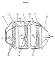
- Fig. 1 shows a schematic view of three cathode gas serially connected fuel cell stack modules according to an embodiment of the invention.
- Fig. 2 shows a schematic view of four cathode gas serially connected fuel cell stack modules and in four different load situations according to an embodiment of the invention.
- Position number overview 101: Fuel cell stacks of the first primary stack module.
- 102 Fuel cell stacks of the second secondary stack module.
- 103 Fuel cell stacks of the third secondary stack module.
- 214 Fourth secondary fuel cell stack module.
- 122, 222 Second intermediate channel.
- 223 Third intermediate channel.
- 132, 232 Second common cathode gas outlet side manifold (of the third / fourth stack module).
- 181, 281 Inlet cathode gas for the first, primary stack module.
- 182, 282 Cathode gas stream from the first, primary stack module to the second, secondary stack module.
- 183, 283 Cathode gas stream from the second, secondary stack module to the third, secondary stack module.
- 284 Cathode gas stream from the third, secondary stack module to the fourth, secondary stack module.
- 192, 292 Additional cold cathode gas inlet between second and third stack module.
- 293 Additional cold cathode gas inlet between third and fourth stack module.
- Fig. 1 shows one embodiment of a SOFC fuel cell stack assembly comprising three stack modules 111, 112, 113 in cathode gas serial connection.
- Each stack module comprises four separate SOFC stacks 101, 102, 103 with a cathode gas side manifolding.
- the four modules are assembled in a square, viz. two stacks high and two stacks wide.
- a sealant is provided between the stacks in a module and between each stack and the module cassette surrounding the modules, said sealant providing a substantially gas tight connection.
- One single side manifold 131 common to all four stacks of the first primary module 111 allows a cathode gas supply 181, i.e. one common gas supply to all four stacks in the primary module.
- primary is here meant the first module in the series which receives "fresh" cathode gas that has been preheated, but not previously run through a stack module.
- All the fuel cells are provided with anode gas inlets through a separate anode gas supply for each stack module (not shown).
- the following two secondary modules 112, 113 are cathode gas serial connected to the first primary module either directly by connecting the cathode gas outlet side manifold of one stack module to the cathode gas inlet side manifold of the next stack module in the series or as shown in Fig. 1 by connecting the cathode gas outlet side manifold of one stack module via an intermediate channel 121, 122 to the cathode gas inlet side manifold of the next stack module in the series.
- secondary modules is here meant stack modules receiving cathode gas which has at least partially been run through a preceding stack module in the series.
- an additional relative cold cathode gas inlet 191, 192 is provided between the serially connected stack modules.
- This additional supply of cold cathode gas serves to ensure the correct operating temperature of the cathode gas supplied to each of the secondary stack modules.
- only the primary stack module requires a supplementary cathode gas pre-heater (not shown).
- the anode gas supply for the first 112 or the second 113 or both the secondary stack modules 112, 113 has been minimized or totally shut off.
- the relevant additional supply of cold cathode air is regulated or shut off.
- a common cathode gas outlet side manifold is provided at the end of the assembly, cf. the drawing. In the illustrated embodiment this manifold is common to all four stack in the last secondary module 113 of the series.
- Fig. 2 shows a cathode gas serially connected SOFC stack module assembly comprising four modules 211, 212, 213, 214, one primary module 211 receiving "fresh" cathode gas and three secondary modules 212, 213, 214 each receiving partially used cathode gas from the preceding stack module in the series.
- Fig. 2 The set-up of Fig. 2 is analogous with the described set-up of Fig. 1 .
- Four load situations are shown, viz. 25%, 50%, 75% and 100% load.
- all the stack modules only receive cathode gas 281 from the first common cathode gas inlet side manifold, and only the primary stack module receives operation anode gas (not shown).
- the secondary modules receive hot, partially used cathode gas 282, 283, 284 which ensures the correct stand-by temperature of the three stand by stack modules 212, 213, 214.
- Stand-by stacks Since the stand-by stacks are kept warm by the cathode outlet of the up-stream stacks still in operation, the heat losses from a stack in operation are hence the same in all four load configurations. Accordingly, the part-load operation takes place with the same efficiency as the full load. Stand-by stacks require anode protection either in the form of an electric potential or in the form of safety gas or anode off-gas from the stacks still in operation.
Landscapes
- Engineering & Computer Science (AREA)
- Chemical & Material Sciences (AREA)
- Life Sciences & Earth Sciences (AREA)
- Manufacturing & Machinery (AREA)
- Sustainable Development (AREA)
- Sustainable Energy (AREA)
- Chemical Kinetics & Catalysis (AREA)
- Electrochemistry (AREA)
- General Chemical & Material Sciences (AREA)
- Combustion & Propulsion (AREA)
- Fuel Cell (AREA)
Description
- The invention relates to a process of running modular fuel cell stack, more specifically to stack modules with a serial connection of the cathode gas inlets and outlets, more specifically to stack modules each having one inlet and one outlet common cathode gas side manifold for all the fuel cells in a module, in particular for Solid Oxide Fuel Cell (SOFC) stacks.
- The electro-chemical reactions and the function of a fuel cell is not the essence of the present invention, thus this is not explained in greater detail here, but considered known to a person skilled in the art.
- To increase the voltage produced by the SOFC, several cell units are assembled to form a stack and are linked together by interconnects. These layers of the stack are sealed together by means of a gas tight and temperature resistant seal, such as glass, along some or all edges. There is a feasible limit to the size of stacks, to the area of each cell as well as to the number of cells which are assembled. The failure risk of a fuel cell stack increases with the number of cells and the size of the area. To increase the effect produced by SOFC it is therefore known to connect several stacks instead of simply increasing the cell area and number of cells in a single stack. The stacks can be connected in series and in parallel both on the electrical side and on the anode gas and cathode gas side of the stacks.
-
US 20060172176 A1 andUS 6033794 show examples of serially connected fuel cell stacks, but not how to realize the connection.US 6403247 describes fuel cell stacks sharing a common gas input chamber, but a not serial connection where a common chamber connects the outlet of one stack or stack assembly to the inlet of another. -
US2007184315 describes a fuel cell system comprising a plurality of fuel cell stacks. The stacks may be connected electrically in any sequence desired, such as in series, in parallel, or as combinations thereof or electrically independent. The electrical performance of each stack is optimized by some metric, or the operating temperature of the stack is controlled by controlling the internal operating temperature of the stack, which in turn is controlled by controlling the output voltage, the output current, or the load of each stack independently of the other stacks. In large fuel cell systems having a large plurality of stacks, adjacent stack may of necessity be grouped as stack pairs with a joint electrical control rather than an individual control, but at some sacrifice in optimal operation. -
DE10256281 describes a fuel cell system using a combination of polymer electrolyte membrane fuel cell stacks operated at different temperatures. -
US 6083636 discloses a fuel cell power system for producing electricity, said system comprising an assembly of fuel cell stacks adapted for operating at different operating temperatures, wherein said operating temperatures vary between two or more of said fuel cell stacks in said assembly, and wherein each of said fuel cell stacks includes means for receiving reactants for electrochemically producing electricity. - In spite of the presented known solutions to the connection problem of several fuel cell stacks, all of them have some of the inherent problems:
- Though several stacks are connected in single modules, still the cathode gas manifolding has not been equally simplified.
- When several stacks or several modules are connected in series, an extensive channelling/piping is necessary to connect to cathode and anode gas.
- Connecting several stacks to increase effect also increases the supply system demand (heat exchangers for cooling and pre-heating).
- Relative high temperature fuel cells, such as Solid Oxide Fuel Cell stacks has relative long start-up and shut-down periods.
- SOFC assemblies of several stacks with relative large effect output, have a low flexibility towards varying the effect output.
- It is an object of the present invention to solve the mentioned problems by providing a new process of running of a SOFC stack assembly for at least two or more fuel cell stacks. The process is defined in claim 1.
- The SOFC stack assembly comprises serially connected stack modules, each module comprising at least one stack, with a simplified connection of the modules in the series omitting the necessity of an extensive extra channelling and piping and reduces the necessity of heat exchangers for cooling and heating.
- More specifically, it is an object of the invention to provide a SOFC stack assembly comprising serially connected stack modules, each module comprising at least one stack, with a simplified connection of the modules in the series omitting the necessity of an extensive extra channelling and piping.
- An object of the invention is also to provide a SOFC stack assembly which reduces the necessity of heat exchangers for cooling and heating.
- It is an important further object of the invention to provide a SOFC stack assembly with an increased effect flexibility allowing it to quickly increase or decrease the power output without necessitating long start-up or shut-down procedures.
- A further object of the invention is to provide a SOFC stack assembly with a simplified cathode gas side manifolding system common to all stacks in a stack module.
- A further object of the invention is to provide a SOFC stack assembly, which is compact relative to the effect output and which is relatively insensitive to variations in the pressure loss over the stacks in the assembly.
- A further object of the invention is to provide a SOFC stack assembly which inherently allows simple connections for a surplus injection of process gases or fluids.
- These and other objects are achieved by the invention as described below.
- The invention is a particularly simple way of connecting fuel cell stacks in series on the cathode gas side.
- The fuel cell stacks are made with air side manifolds, i.e. the cathode inlet and outlet to each individual cell in the stacks are open to the sides of the stacks. A number of stacks are aligned side by side and assembled into a stack module with cathode inlets on one face of the module and the cathode outlets on the other face of the module. The stack modules are serially connected in a simple manner by placing the stack modules one after the other, so that the outlet face of the first module faces the inlet face of the second module and so on. In the chamber between two stack modules, the air is cooled for example by addition of cold quench air or by a heat exchanger.
- In addition, the invention offers a convenient way of operating the fuel cell system at fractions of the full load. When the SOFC stack assembly runs at full load, all stack modules in the assembly are provided with cathode gas via the common cathode gas side manifolds and with anode gas via anode gas inlets to each module. But when a partial load is required, only the necessary stack modules are provided with anode gas in a sufficient volume to provide considerable, electrical effect production of those stacks. For those stacks which are not necessary in the partial load mode, the anode gas supply is either shut completely off or turned down to a minimum flow sufficient to protect the stand-by stack(s) against degradation. The resulting great advantage is that since both effect producing and stand-by stacks are provided with hot cathode gas, the stand-by stacks are always heated to the desired operation temperature. Thus they are ready to quickly shift from stand-by mode to operation mode when anode gas is again supplied to the stack(s). This provides for a so far unseen flexibility of effect output from a SOFC stack assembly.
- The invention provides a range of advantages of which some are listed below:
- 1. A very simple mechanical structure: fewer tubes and a highly compact structure. For example, four stack modules with four stacks in each gives a 16-stack unit with one cathode inlet string, one cathode outlet string, one fuel inlet string and one fuel outlet string. In addition, three cold strings for quench cooling are required.
- 2. The arrangement of the stack modules allows a part-load operation without causing the problem of the stacks becoming too cold for an efficient operation.
- 3. When numerous stacks are connected in parallel with the gas supplies, then the pressure loss of the individual stacks must be closely matched in order to run all stacks at suitable operating points. The latter requires an extensive quality control and makes the production of such stacks expensive. A significantly increased tolerance towards differences in pressure losses is achieved by assembling a small number of stacks in a stack module and by connecting them in series on the cathode side.
- 4. Balance-of-plant components, like the high-temperature heat exchanger for cathode air preheating, can be integrated at the ends of the duct formed by the serially connected stacks, further adding to a compact and cost-effective mechanical structure.
- The invention is further illustrated below by means of the accompanying drawings showing examples of embodiments of the invention.
-
Fig. 1 shows a schematic view of three cathode gas serially connected fuel cell stack modules according to an embodiment of the invention. -
Fig. 2 shows a schematic view of four cathode gas serially connected fuel cell stack modules and in four different load situations according to an embodiment of the invention. - Position number overview:
101: Fuel cell stacks of the first primary stack module. 102: Fuel cell stacks of the second secondary stack module. 103: Fuel cell stacks of the third secondary stack module. 111, 211: First primary fuel cell stack module. 112, 212: Second secondary fuel cell stack module. 113, 213: Third secondary fuel cell stack module. 214: Fourth secondary fuel cell stack module. 121, 221: First intermediate channel. 122, 222: Second intermediate channel. 223: Third intermediate channel. 131, 231: First common cathode gas inlet side manifold (of the first stack module). 132, 232: Second common cathode gas outlet side manifold (of the third / fourth stack module). 181, 281: Inlet cathode gas for the first, primary stack module. 182, 282: Cathode gas stream from the first, primary stack module to the second, secondary stack module. 183, 283: Cathode gas stream from the second, secondary stack module to the third, secondary stack module. 284: Cathode gas stream from the third, secondary stack module to the fourth, secondary stack module. 191, 291: Additional cold cathode gas inlet between first and second stack module. 192, 292: Additional cold cathode gas inlet between second and third stack module. 293: Additional cold cathode gas inlet between third and fourth stack module. -
Fig. 1 shows one embodiment of a SOFC fuel cell stack assembly comprising threestack modules separate SOFC stacks single side manifold 131 common to all four stacks of the firstprimary module 111 allows acathode gas supply 181, i.e. one common gas supply to all four stacks in the primary module. By primary is here meant the first module in the series which receives "fresh" cathode gas that has been preheated, but not previously run through a stack module. - All the fuel cells are provided with anode gas inlets through a separate anode gas supply for each stack module (not shown). The following two
secondary modules Fig. 1 by connecting the cathode gas outlet side manifold of one stack module via anintermediate channel cathode gas inlet - When operating at part load, the anode gas supply for the first 112 or the second 113 or both the
secondary stack modules - At the end of the assembly, cf. the drawing, a common cathode gas outlet side manifold is provided. In the illustrated embodiment this manifold is common to all four stack in the last
secondary module 113 of the series. -
Fig. 2 shows a cathode gas serially connected SOFC stack module assembly comprising fourmodules primary module 211 receiving "fresh" cathode gas and threesecondary modules - The set-up of
Fig. 2 is analogous with the described set-up ofFig. 1 . Four load situations are shown, viz. 25%, 50%, 75% and 100% load. As can be seen, in the 25% load situation all the stack modules only receivecathode gas 281 from the first common cathode gas inlet side manifold, and only the primary stack module receives operation anode gas (not shown). The secondary modules receive hot, partially usedcathode gas stack modules - In the 50%, 75% and 100% load situations, more stack modules receive operation anode gas (not shown), and accordingly those stack modules in operation receive an additional amount of
cold cathode gas - Since the stand-by stacks are kept warm by the cathode outlet of the up-stream stacks still in operation, the heat losses from a stack in operation are hence the same in all four load configurations. Accordingly, the part-load operation takes place with the same efficiency as the full load. Stand-by stacks require anode protection either in the form of an electric potential or in the form of safety gas or anode off-gas from the stacks still in operation.
-
P = 50 kW, U f = 70%, 18 x 18 cm2 counter-flow stacks Config Fuel Elec. Eff. Power Density Excess air ratio △T Air in/out HeX P inlet (mbarg) XO2 Outlet Parallel Methane Base Base Base Base Base 150 0.17 Cascaded, 4 layers Methane 100% 106% 61% 42% 57% 350 0.14 P=50kW Methane Methane Methane Base Case Quench Air Intercooler Serial Cell Groups 1 4 4 Net Efficiency 49.9 49.9 49.9 Total Number of Cells 1264 1196 1200 Coal Syngas Coal Syngas Coal Syngas Serial Cell Groups 1 4 4 Net Efficiency 45.4 45.2 45.5 Total Number of Cells 1266 1216 1204
Claims (5)
- A process of running a Solid Oxide Fuel Cell stack assembly suited for a partial load running, said assembly comprising a plurality of fuel cells arranged in at least two cathode gas serially connected stack modules and comprising at least one stack in each module, where cathode gas exhaust from a first primary stack module is carried to the cathode gas inlet of the next at least one secondary serially connected stack module, wherein each stack module has a first cathode gas inlet side manifold common to all the stacks of said module and second cathode gas outlet side manifold common to all the stacks of said module, and wherein the cathode gas is serially connected from the first primary stack module to the next at least one secondary stack module of the serial connection through said common side manifolds, said process comprising the steps of- providing at least two cathode gas serially connected stack modules, one primary stack module and at least one secondary stack module- providing at least the first stack module in the series with anode gas- providing the cathode gas inlet of the first primary stack module in the series with preheated cathode gas- providing the cathode gas inlet of the at least one secondary stack module in the series with hot exhaust cathode gas from the cathode gas outlet of the preceding stack module- providing anode gas to the primary stack, said anode gas being carried to none or only to some of the secondary stack modules in the assembly.
- A process of running a Solid Oxide Fuel Cell stack assembly according to claim 1, wherein the exhaust cathode gas provided to the cathode gas inlet of the at least one secondary stack module provided with anode gas is cooled by means of a heat exchanger or by inlet of additional cold cathode gas.
- A process according to claim 1 or 2, wherein the assembly comprises two stack modules.
- A process according to claim 1 or 2, wherein the assembly comprises four stack modules.
- A process according to claim 4 suited to run at approximately 25%, 50%, 75% or 100% load,
when running at 25% load only the first stack module in the series is provided with anode gas,
when running at 50% load only the first and the second stack module in the series are provided with anode gas and only the cathode gas provided to the second stack module is cooled,
when running at 75% load only the first, the second and the third stack module in the series are provided with anode gas and only the cathode gas provided to the second and third stack module is cooled,
when running at 100% load all the stack modules in the series are provided with anode gas and the cathode gas provided to the second, third and fourth stack module is cooled.
Applications Claiming Priority (1)
| Application Number | Priority Date | Filing Date | Title |
|---|---|---|---|
| DKPA200900647 | 2009-05-22 |
Publications (2)
| Publication Number | Publication Date |
|---|---|
| EP2254182A1 EP2254182A1 (en) | 2010-11-24 |
| EP2254182B1 true EP2254182B1 (en) | 2012-08-22 |
Family
ID=42320099
Family Applications (1)
| Application Number | Title | Priority Date | Filing Date |
|---|---|---|---|
| EP10004782A Not-in-force EP2254182B1 (en) | 2009-05-22 | 2010-05-06 | Process of running a serial connected fuel cell stack module assembly |
Country Status (8)
| Country | Link |
|---|---|
| US (1) | US8841042B2 (en) |
| EP (1) | EP2254182B1 (en) |
| JP (1) | JP5361798B2 (en) |
| KR (1) | KR20100126198A (en) |
| CN (1) | CN101944627B (en) |
| CA (1) | CA2704914A1 (en) |
| ES (1) | ES2391682T3 (en) |
| RU (1) | RU2534021C2 (en) |
Families Citing this family (11)
| Publication number | Priority date | Publication date | Assignee | Title |
|---|---|---|---|---|
| DE102011077695A1 (en) | 2011-06-17 | 2012-12-20 | Siemens Aktiengesellschaft | Electric energy storage |
| US9118052B2 (en) * | 2011-09-27 | 2015-08-25 | Philips 66 Company | Integrated natural gas powered SOFC systems |
| JP6016520B2 (en) * | 2012-08-22 | 2016-10-26 | 三菱日立パワーシステムズ株式会社 | Fuel cell module |
| US10985392B2 (en) * | 2013-05-24 | 2021-04-20 | Hydrogenics Corporation | System and method for controlling voltage of fuel cell |
| WO2017184987A1 (en) | 2016-04-22 | 2017-10-26 | Fuelcell Energy, Inc. | Fuel cell module housing with field replaceable stacks |
| CN107464944B (en) | 2016-05-27 | 2021-02-02 | 通用电气公司 | Fuel cell system and method of operating the same |
| US10854899B2 (en) | 2016-11-04 | 2020-12-01 | Cummins Enterprise Llc | Power generation system using cascaded fuel cells and associated methods thereof |
| GB201713140D0 (en) | 2017-08-16 | 2017-09-27 | Ceres Ip Co Ltd | Fuel cell multi cell layer/welding process |
| DE102018214643A1 (en) | 2018-08-29 | 2020-03-05 | Nikola Corp. | Method for operating a fuel cell system for a motor vehicle |
| CN114069009B (en) * | 2020-08-03 | 2023-07-11 | 国家能源投资集团有限责任公司 | Pile power generation module |
| EP4480024A1 (en) * | 2022-02-17 | 2024-12-25 | WattAnyWhere SA | A method and system to produce electrical power in an autonomous stationary situation using a chemical fuel obtained from organic source |
Family Cites Families (17)
| Publication number | Priority date | Publication date | Assignee | Title |
|---|---|---|---|---|
| JPH03108271A (en) * | 1989-09-20 | 1991-05-08 | Mitsubishi Electric Corp | Fuel cell power generating system |
| US6083636A (en) * | 1994-08-08 | 2000-07-04 | Ztek Corporation | Fuel cell stacks for ultra-high efficiency power systems |
| US6033794A (en) | 1997-12-10 | 2000-03-07 | The United States Of America As Represented By The United States Department Of Energy | Multi-stage fuel cell system method and apparatus |
| US6475655B1 (en) * | 1999-06-23 | 2002-11-05 | Daihatsu Motor Co., Ltd. | Fuel cell system with hydrogen gas separation |
| US6403247B1 (en) | 1999-12-03 | 2002-06-11 | International Fuel Cells, Llc | Fuel cell power plant having an integrated manifold system |
| US7727663B2 (en) * | 2001-07-18 | 2010-06-01 | Tel-Aviv University Future Technology Development L.P. | Fuel cell with proton conducting membrane and with improved water and fuel management |
| DE10256281A1 (en) * | 2002-12-03 | 2004-06-24 | Daimlerchrysler Ag | Fuel cell system using combination of polymer electrolyte membrane fuel cell stacks operated at different temperatures |
| WO2004082058A1 (en) * | 2003-03-13 | 2004-09-23 | Tokyo Gas Company Limited | Solid-oxide shaped fuel cell module |
| KR20060086950A (en) * | 2003-10-21 | 2006-08-01 | 알베르타 리써치 카운실 인코포레이티드 | Method and device for operation control of solid oxide fuel cell |
| WO2005041339A1 (en) * | 2003-10-23 | 2005-05-06 | Hydrogenics Corporation | A fuel cell power system having multiple fuel cell modules |
| KR101127028B1 (en) * | 2003-11-19 | 2012-03-26 | 아쿠아훼아리 가부시키가이샤 | Fuel cell |
| US7615299B2 (en) | 2005-01-28 | 2009-11-10 | Delphi Technologies, Inc. | Method and apparatus for thermal, mechanical, and electrical optimization of a solid-oxide fuel cell stack |
| US20070184315A1 (en) * | 2006-02-09 | 2007-08-09 | Kelly Sean M | Control of fuel cell stack electrical operating conditions |
| RU2328060C1 (en) * | 2006-11-23 | 2008-06-27 | Федеральное государственное предприятие "ЦНИИ судовой электротехники и технологии" (ФГУП "ЦНИИ СЭТ") | Fuel element and fuel-cell battery |
| JP5105930B2 (en) | 2007-03-29 | 2012-12-26 | 東邦瓦斯株式会社 | Solid oxide fuel cell module |
| RU69322U1 (en) * | 2007-07-30 | 2007-12-10 | Общество с ограниченной ответственностью "Национальная инновационная компания "Новые энергетические проекты" (ООО "Национальная инновационная компания "НЭП") | FUEL BATTERY FOR A STAND-ALONE POWER SUPPLY |
| RU2355072C1 (en) * | 2007-10-03 | 2009-05-10 | Общество с ограниченной ответственностью "Национальная инновационная компания "Новые энергетические проекты" (ООО "Национальная инновационная компания "НЭП") | Fuel-cell battery |
-
2010
- 2010-05-06 ES ES10004782T patent/ES2391682T3/en active Active
- 2010-05-06 EP EP10004782A patent/EP2254182B1/en not_active Not-in-force
- 2010-05-12 US US12/778,520 patent/US8841042B2/en not_active Expired - Fee Related
- 2010-05-19 KR KR1020100046889A patent/KR20100126198A/en not_active Ceased
- 2010-05-21 JP JP2010116859A patent/JP5361798B2/en not_active Expired - Fee Related
- 2010-05-21 CA CA2704914A patent/CA2704914A1/en not_active Abandoned
- 2010-05-21 CN CN201010225486.0A patent/CN101944627B/en not_active Expired - Fee Related
- 2010-05-21 RU RU2010120438/07A patent/RU2534021C2/en not_active IP Right Cessation
Also Published As
| Publication number | Publication date |
|---|---|
| RU2534021C2 (en) | 2014-11-27 |
| JP2010282960A (en) | 2010-12-16 |
| CN101944627A (en) | 2011-01-12 |
| US20100297515A1 (en) | 2010-11-25 |
| US8841042B2 (en) | 2014-09-23 |
| AU2010202060A1 (en) | 2010-12-09 |
| JP5361798B2 (en) | 2013-12-04 |
| CA2704914A1 (en) | 2010-11-22 |
| HK1153044A1 (en) | 2012-03-16 |
| ES2391682T3 (en) | 2012-11-28 |
| EP2254182A1 (en) | 2010-11-24 |
| KR20100126198A (en) | 2010-12-01 |
| CN101944627B (en) | 2016-02-03 |
| RU2010120438A (en) | 2011-11-27 |
Similar Documents
| Publication | Publication Date | Title |
|---|---|---|
| EP2254182A1 (en) | Serial connected fuel cell stack module assembly | |
| CN102282707B (en) | Fuel cell without bipolar plates | |
| EP2559090B1 (en) | Thermal management in a fuel cell stack | |
| US10396389B2 (en) | Fuel cell stack | |
| US10181608B2 (en) | Fuel cell stack and fuel cell module | |
| CN103907233A (en) | The fuel cell | |
| US20040126640A1 (en) | Fuel cell module, combined cycle power system, and power generation method | |
| US20160133955A1 (en) | Fuel cell module, combined power generation system including the same, and temperature control method of fuel cell power generation section | |
| JP2013527564A5 (en) | ||
| CA2427419A1 (en) | A hybrid power system employing fluid regulating elements for controlling various operational parameters of the system | |
| US6756144B2 (en) | Integrated recuperation loop in fuel cell stack | |
| US7374834B2 (en) | Gas flow panels integrated with solid oxide fuel cell stacks | |
| TW201505248A (en) | Solid oxide stacking system with thermally matched stacked integrated heat exchanger | |
| US20050084725A1 (en) | Multi-cell fuel cell layer and system | |
| US20250149602A1 (en) | A solid oxide cell stack system comprising a multi-stream solid oxide cell stack heat exchanger | |
| CA2844467C (en) | Fuel cell stack with thin endplate with integrated gas distribution tubes | |
| KR102244133B1 (en) | Connection type fuel cell system | |
| HK1153044B (en) | Serial connected fuel cell stack module assembly |
Legal Events
| Date | Code | Title | Description |
|---|---|---|---|
| PUAI | Public reference made under article 153(3) epc to a published international application that has entered the european phase |
Free format text: ORIGINAL CODE: 0009012 |
|
| AK | Designated contracting states |
Kind code of ref document: A1 Designated state(s): AL AT BE BG CH CY CZ DE DK EE ES FI FR GB GR HR HU IE IS IT LI LT LU LV MC MK MT NL NO PL PT RO SE SI SK SM TR |
|
| AX | Request for extension of the european patent |
Extension state: BA ME RS |
|
| 17P | Request for examination filed |
Effective date: 20110524 |
|
| RIC1 | Information provided on ipc code assigned before grant |
Ipc: H01M 8/24 20060101ALI20111103BHEP Ipc: H01M 8/04 20060101AFI20111103BHEP |
|
| RTI1 | Title (correction) |
Free format text: PROCESS OF RUNNING A SERIAL CONNECTED FUEL CELL STACK MODULE ASSEMBLY |
|
| GRAP | Despatch of communication of intention to grant a patent |
Free format text: ORIGINAL CODE: EPIDOSNIGR1 |
|
| GRAS | Grant fee paid |
Free format text: ORIGINAL CODE: EPIDOSNIGR3 |
|
| GRAA | (expected) grant |
Free format text: ORIGINAL CODE: 0009210 |
|
| AK | Designated contracting states |
Kind code of ref document: B1 Designated state(s): AL AT BE BG CH CY CZ DE DK EE ES FI FR GB GR HR HU IE IS IT LI LT LU LV MC MK MT NL NO PL PT RO SE SI SK SM TR |
|
| REG | Reference to a national code |
Ref country code: GB Ref legal event code: FG4D |
|
| REG | Reference to a national code |
Ref country code: CH Ref legal event code: EP |
|
| REG | Reference to a national code |
Ref country code: IE Ref legal event code: FG4D |
|
| REG | Reference to a national code |
Ref country code: AT Ref legal event code: REF Ref document number: 572372 Country of ref document: AT Kind code of ref document: T Effective date: 20120915 |
|
| REG | Reference to a national code |
Ref country code: DE Ref legal event code: R096 Ref document number: 602010002327 Country of ref document: DE Effective date: 20121018 |
|
| REG | Reference to a national code |
Ref country code: SE Ref legal event code: TRGR |
|
| REG | Reference to a national code |
Ref country code: NL Ref legal event code: T3 |
|
| REG | Reference to a national code |
Ref country code: ES Ref legal event code: FG2A Ref document number: 2391682 Country of ref document: ES Kind code of ref document: T3 Effective date: 20121128 |
|
| REG | Reference to a national code |
Ref country code: NO Ref legal event code: T2 Effective date: 20120822 |
|
| REG | Reference to a national code |
Ref country code: AT Ref legal event code: MK05 Ref document number: 572372 Country of ref document: AT Kind code of ref document: T Effective date: 20120822 |
|
| REG | Reference to a national code |
Ref country code: LT Ref legal event code: MG4D Effective date: 20120829 |
|
| PG25 | Lapsed in a contracting state [announced via postgrant information from national office to epo] |
Ref country code: AT Free format text: LAPSE BECAUSE OF FAILURE TO SUBMIT A TRANSLATION OF THE DESCRIPTION OR TO PAY THE FEE WITHIN THE PRESCRIBED TIME-LIMIT Effective date: 20120822 Ref country code: LT Free format text: LAPSE BECAUSE OF FAILURE TO SUBMIT A TRANSLATION OF THE DESCRIPTION OR TO PAY THE FEE WITHIN THE PRESCRIBED TIME-LIMIT Effective date: 20120822 Ref country code: IS Free format text: LAPSE BECAUSE OF FAILURE TO SUBMIT A TRANSLATION OF THE DESCRIPTION OR TO PAY THE FEE WITHIN THE PRESCRIBED TIME-LIMIT Effective date: 20121222 Ref country code: HR Free format text: LAPSE BECAUSE OF FAILURE TO SUBMIT A TRANSLATION OF THE DESCRIPTION OR TO PAY THE FEE WITHIN THE PRESCRIBED TIME-LIMIT Effective date: 20120822 |
|
| PG25 | Lapsed in a contracting state [announced via postgrant information from national office to epo] |
Ref country code: LV Free format text: LAPSE BECAUSE OF FAILURE TO SUBMIT A TRANSLATION OF THE DESCRIPTION OR TO PAY THE FEE WITHIN THE PRESCRIBED TIME-LIMIT Effective date: 20120822 Ref country code: GR Free format text: LAPSE BECAUSE OF FAILURE TO SUBMIT A TRANSLATION OF THE DESCRIPTION OR TO PAY THE FEE WITHIN THE PRESCRIBED TIME-LIMIT Effective date: 20121123 Ref country code: PT Free format text: LAPSE BECAUSE OF FAILURE TO SUBMIT A TRANSLATION OF THE DESCRIPTION OR TO PAY THE FEE WITHIN THE PRESCRIBED TIME-LIMIT Effective date: 20121224 Ref country code: SI Free format text: LAPSE BECAUSE OF FAILURE TO SUBMIT A TRANSLATION OF THE DESCRIPTION OR TO PAY THE FEE WITHIN THE PRESCRIBED TIME-LIMIT Effective date: 20120822 |
|
| PG25 | Lapsed in a contracting state [announced via postgrant information from national office to epo] |
Ref country code: RO Free format text: LAPSE BECAUSE OF FAILURE TO SUBMIT A TRANSLATION OF THE DESCRIPTION OR TO PAY THE FEE WITHIN THE PRESCRIBED TIME-LIMIT Effective date: 20120822 Ref country code: CZ Free format text: LAPSE BECAUSE OF FAILURE TO SUBMIT A TRANSLATION OF THE DESCRIPTION OR TO PAY THE FEE WITHIN THE PRESCRIBED TIME-LIMIT Effective date: 20120822 Ref country code: EE Free format text: LAPSE BECAUSE OF FAILURE TO SUBMIT A TRANSLATION OF THE DESCRIPTION OR TO PAY THE FEE WITHIN THE PRESCRIBED TIME-LIMIT Effective date: 20120822 |
|
| PG25 | Lapsed in a contracting state [announced via postgrant information from national office to epo] |
Ref country code: SK Free format text: LAPSE BECAUSE OF FAILURE TO SUBMIT A TRANSLATION OF THE DESCRIPTION OR TO PAY THE FEE WITHIN THE PRESCRIBED TIME-LIMIT Effective date: 20120822 Ref country code: PL Free format text: LAPSE BECAUSE OF FAILURE TO SUBMIT A TRANSLATION OF THE DESCRIPTION OR TO PAY THE FEE WITHIN THE PRESCRIBED TIME-LIMIT Effective date: 20120822 |
|
| PLBE | No opposition filed within time limit |
Free format text: ORIGINAL CODE: 0009261 |
|
| STAA | Information on the status of an ep patent application or granted ep patent |
Free format text: STATUS: NO OPPOSITION FILED WITHIN TIME LIMIT |
|
| 26N | No opposition filed |
Effective date: 20130523 |
|
| PG25 | Lapsed in a contracting state [announced via postgrant information from national office to epo] |
Ref country code: BG Free format text: LAPSE BECAUSE OF FAILURE TO SUBMIT A TRANSLATION OF THE DESCRIPTION OR TO PAY THE FEE WITHIN THE PRESCRIBED TIME-LIMIT Effective date: 20121122 |
|
| REG | Reference to a national code |
Ref country code: DE Ref legal event code: R097 Ref document number: 602010002327 Country of ref document: DE Effective date: 20130523 |
|
| PG25 | Lapsed in a contracting state [announced via postgrant information from national office to epo] |
Ref country code: CY Free format text: LAPSE BECAUSE OF FAILURE TO SUBMIT A TRANSLATION OF THE DESCRIPTION OR TO PAY THE FEE WITHIN THE PRESCRIBED TIME-LIMIT Effective date: 20120822 |
|
| PG25 | Lapsed in a contracting state [announced via postgrant information from national office to epo] |
Ref country code: MC Free format text: LAPSE BECAUSE OF FAILURE TO SUBMIT A TRANSLATION OF THE DESCRIPTION OR TO PAY THE FEE WITHIN THE PRESCRIBED TIME-LIMIT Effective date: 20120822 |
|
| REG | Reference to a national code |
Ref country code: IE Ref legal event code: MM4A |
|
| PG25 | Lapsed in a contracting state [announced via postgrant information from national office to epo] |
Ref country code: IE Free format text: LAPSE BECAUSE OF NON-PAYMENT OF DUE FEES Effective date: 20130506 |
|
| PG25 | Lapsed in a contracting state [announced via postgrant information from national office to epo] |
Ref country code: DK Free format text: LAPSE BECAUSE OF NON-PAYMENT OF DUE FEES Effective date: 20120822 |
|
| PG25 | Lapsed in a contracting state [announced via postgrant information from national office to epo] |
Ref country code: MT Free format text: LAPSE BECAUSE OF FAILURE TO SUBMIT A TRANSLATION OF THE DESCRIPTION OR TO PAY THE FEE WITHIN THE PRESCRIBED TIME-LIMIT Effective date: 20120822 |
|
| PG25 | Lapsed in a contracting state [announced via postgrant information from national office to epo] |
Ref country code: SM Free format text: LAPSE BECAUSE OF FAILURE TO SUBMIT A TRANSLATION OF THE DESCRIPTION OR TO PAY THE FEE WITHIN THE PRESCRIBED TIME-LIMIT Effective date: 20120822 |
|
| REG | Reference to a national code |
Ref country code: NO Ref legal event code: CHAD Owner name: HALDOR TOPSOEE A/S, DK |
|
| PG25 | Lapsed in a contracting state [announced via postgrant information from national office to epo] |
Ref country code: TR Free format text: LAPSE BECAUSE OF FAILURE TO SUBMIT A TRANSLATION OF THE DESCRIPTION OR TO PAY THE FEE WITHIN THE PRESCRIBED TIME-LIMIT Effective date: 20120822 |
|
| REG | Reference to a national code |
Ref country code: DE Ref legal event code: R081 Ref document number: 602010002327 Country of ref document: DE Owner name: HALDOR TOPSOE A/S, DK Free format text: FORMER OWNER: TOPSOE FUEL CELL A/S, KONGENS LYNGBY, DK |
|
| PG25 | Lapsed in a contracting state [announced via postgrant information from national office to epo] |
Ref country code: HU Free format text: LAPSE BECAUSE OF FAILURE TO SUBMIT A TRANSLATION OF THE DESCRIPTION OR TO PAY THE FEE WITHIN THE PRESCRIBED TIME-LIMIT; INVALID AB INITIO Effective date: 20100506 Ref country code: LU Free format text: LAPSE BECAUSE OF NON-PAYMENT OF DUE FEES Effective date: 20130506 Ref country code: MK Free format text: LAPSE BECAUSE OF FAILURE TO SUBMIT A TRANSLATION OF THE DESCRIPTION OR TO PAY THE FEE WITHIN THE PRESCRIBED TIME-LIMIT Effective date: 20120822 |
|
| REG | Reference to a national code |
Ref country code: ES Ref legal event code: PC2A Owner name: HALDOR TOPSOE A/S Effective date: 20150731 |
|
| REG | Reference to a national code |
Ref country code: NL Ref legal event code: SD Effective date: 20150805 |
|
| REG | Reference to a national code |
Ref country code: GB Ref legal event code: 732E Free format text: REGISTERED BETWEEN 20150806 AND 20150812 |
|
| REG | Reference to a national code |
Ref country code: CH Ref legal event code: NV Representative=s name: GLN S.A., CH Ref country code: CH Ref legal event code: PUE Owner name: HALDOR TOPSOEE A/S, DK Free format text: FORMER OWNER: TOPSOE FUEL CELL A/S, DK |
|
| REG | Reference to a national code |
Ref country code: FR Ref legal event code: TP Owner name: HALDOR TOPSOE A/S, DK Effective date: 20150916 |
|
| REG | Reference to a national code |
Ref country code: FR Ref legal event code: PLFP Year of fee payment: 7 |
|
| REG | Reference to a national code |
Ref country code: CH Ref legal event code: PFA Owner name: HALDOR TOPSOEE A/S, DK Free format text: FORMER OWNER: HALDOR TOPSOEE A/S, DK |
|
| REG | Reference to a national code |
Ref country code: FR Ref legal event code: PLFP Year of fee payment: 8 |
|
| REG | Reference to a national code |
Ref country code: FR Ref legal event code: PLFP Year of fee payment: 9 |
|
| PGFP | Annual fee paid to national office [announced via postgrant information from national office to epo] |
Ref country code: CH Payment date: 20180601 Year of fee payment: 9 Ref country code: DE Payment date: 20180529 Year of fee payment: 9 Ref country code: NO Payment date: 20180529 Year of fee payment: 9 Ref country code: FI Payment date: 20180529 Year of fee payment: 9 Ref country code: ES Payment date: 20180601 Year of fee payment: 9 |
|
| PGFP | Annual fee paid to national office [announced via postgrant information from national office to epo] |
Ref country code: NL Payment date: 20180526 Year of fee payment: 9 Ref country code: FR Payment date: 20180525 Year of fee payment: 9 Ref country code: IT Payment date: 20180522 Year of fee payment: 9 Ref country code: BE Payment date: 20180528 Year of fee payment: 9 |
|
| PGFP | Annual fee paid to national office [announced via postgrant information from national office to epo] |
Ref country code: SE Payment date: 20180529 Year of fee payment: 9 |
|
| PG25 | Lapsed in a contracting state [announced via postgrant information from national office to epo] |
Ref country code: AL Free format text: LAPSE BECAUSE OF FAILURE TO SUBMIT A TRANSLATION OF THE DESCRIPTION OR TO PAY THE FEE WITHIN THE PRESCRIBED TIME-LIMIT Effective date: 20120822 |
|
| PGFP | Annual fee paid to national office [announced via postgrant information from national office to epo] |
Ref country code: GB Payment date: 20180529 Year of fee payment: 9 |
|
| REG | Reference to a national code |
Ref country code: CH Ref legal event code: NV Representative=s name: BOVARD SA NEUCHATEL CONSEILS EN PROPRIETE INTE, CH |
|
| REG | Reference to a national code |
Ref country code: DE Ref legal event code: R119 Ref document number: 602010002327 Country of ref document: DE |
|
| REG | Reference to a national code |
Ref country code: NO Ref legal event code: MMEP |
|
| REG | Reference to a national code |
Ref country code: CH Ref legal event code: PL |
|
| REG | Reference to a national code |
Ref country code: NL Ref legal event code: MM Effective date: 20190601 |
|
| GBPC | Gb: european patent ceased through non-payment of renewal fee |
Effective date: 20190506 |
|
| PG25 | Lapsed in a contracting state [announced via postgrant information from national office to epo] |
Ref country code: SE Free format text: LAPSE BECAUSE OF NON-PAYMENT OF DUE FEES Effective date: 20190507 Ref country code: FI Free format text: LAPSE BECAUSE OF NON-PAYMENT OF DUE FEES Effective date: 20190506 Ref country code: LI Free format text: LAPSE BECAUSE OF NON-PAYMENT OF DUE FEES Effective date: 20190531 Ref country code: CH Free format text: LAPSE BECAUSE OF NON-PAYMENT OF DUE FEES Effective date: 20190531 Ref country code: NO Free format text: LAPSE BECAUSE OF NON-PAYMENT OF DUE FEES Effective date: 20190531 |
|
| REG | Reference to a national code |
Ref country code: BE Ref legal event code: MM Effective date: 20190531 |
|
| PG25 | Lapsed in a contracting state [announced via postgrant information from national office to epo] |
Ref country code: DE Free format text: LAPSE BECAUSE OF NON-PAYMENT OF DUE FEES Effective date: 20191203 Ref country code: GB Free format text: LAPSE BECAUSE OF NON-PAYMENT OF DUE FEES Effective date: 20190506 Ref country code: NL Free format text: LAPSE BECAUSE OF NON-PAYMENT OF DUE FEES Effective date: 20190601 Ref country code: IT Free format text: LAPSE BECAUSE OF NON-PAYMENT OF DUE FEES Effective date: 20190506 |
|
| REG | Reference to a national code |
Ref country code: SE Ref legal event code: EUG |
|
| PG25 | Lapsed in a contracting state [announced via postgrant information from national office to epo] |
Ref country code: BE Free format text: LAPSE BECAUSE OF NON-PAYMENT OF DUE FEES Effective date: 20190531 |
|
| PG25 | Lapsed in a contracting state [announced via postgrant information from national office to epo] |
Ref country code: FR Free format text: LAPSE BECAUSE OF NON-PAYMENT OF DUE FEES Effective date: 20190531 |
|
| REG | Reference to a national code |
Ref country code: ES Ref legal event code: FD2A Effective date: 20200925 |
|
| PG25 | Lapsed in a contracting state [announced via postgrant information from national office to epo] |
Ref country code: ES Free format text: LAPSE BECAUSE OF NON-PAYMENT OF DUE FEES Effective date: 20190507 |