EP2254142A2 - Low pressure electrospray ionization system and process for effective transmission of ions - Google Patents
Low pressure electrospray ionization system and process for effective transmission of ions Download PDFInfo
- Publication number
- EP2254142A2 EP2254142A2 EP10005167A EP10005167A EP2254142A2 EP 2254142 A2 EP2254142 A2 EP 2254142A2 EP 10005167 A EP10005167 A EP 10005167A EP 10005167 A EP10005167 A EP 10005167A EP 2254142 A2 EP2254142 A2 EP 2254142A2
- Authority
- EP
- European Patent Office
- Prior art keywords
- esi
- ion
- ion guide
- electrospray
- ions
- Prior art date
- Legal status (The legal status is an assumption and is not a legal conclusion. Google has not performed a legal analysis and makes no representation as to the accuracy of the status listed.)
- Withdrawn
Links
- 150000002500 ions Chemical class 0.000 title claims abstract description 224
- 238000000132 electrospray ionisation Methods 0.000 title claims abstract description 101
- 238000000034 method Methods 0.000 title claims abstract description 10
- 230000005540 biological transmission Effects 0.000 title abstract description 29
- 230000008569 process Effects 0.000 title abstract description 5
- 230000005520 electrodynamics Effects 0.000 claims abstract description 8
- 230000005405 multipole Effects 0.000 claims description 21
- 238000010438 heat treatment Methods 0.000 claims description 5
- 230000001105 regulatory effect Effects 0.000 claims description 4
- 230000015556 catabolic process Effects 0.000 claims description 3
- 239000000203 mixture Substances 0.000 claims description 3
- 239000002516 radical scavenger Substances 0.000 claims description 3
- 239000000523 sample Substances 0.000 abstract description 4
- 239000012488 sample solution Substances 0.000 abstract description 2
- DNXIKVLOVZVMQF-UHFFFAOYSA-N (3beta,16beta,17alpha,18beta,20alpha)-17-hydroxy-11-methoxy-18-[(3,4,5-trimethoxybenzoyl)oxy]-yohimban-16-carboxylic acid, methyl ester Natural products C1C2CN3CCC(C4=CC=C(OC)C=C4N4)=C4C3CC2C(C(=O)OC)C(O)C1OC(=O)C1=CC(OC)=C(OC)C(OC)=C1 DNXIKVLOVZVMQF-UHFFFAOYSA-N 0.000 description 17
- LCQMZZCPPSWADO-UHFFFAOYSA-N Reserpilin Natural products COC(=O)C1COCC2CN3CCc4c([nH]c5cc(OC)c(OC)cc45)C3CC12 LCQMZZCPPSWADO-UHFFFAOYSA-N 0.000 description 17
- QEVHRUUCFGRFIF-SFWBKIHZSA-N Reserpine Natural products O=C(OC)[C@@H]1[C@H](OC)[C@H](OC(=O)c2cc(OC)c(OC)c(OC)c2)C[C@H]2[C@@H]1C[C@H]1N(C2)CCc2c3c([nH]c12)cc(OC)cc3 QEVHRUUCFGRFIF-SFWBKIHZSA-N 0.000 description 17
- BJOIZNZVOZKDIG-MDEJGZGSSA-N reserpine Chemical compound O([C@H]1[C@@H]([C@H]([C@H]2C[C@@H]3C4=C([C]5C=CC(OC)=CC5=N4)CCN3C[C@H]2C1)C(=O)OC)OC)C(=O)C1=CC(OC)=C(OC)C(OC)=C1 BJOIZNZVOZKDIG-MDEJGZGSSA-N 0.000 description 17
- 229960003147 reserpine Drugs 0.000 description 17
- MDMGHDFNKNZPAU-UHFFFAOYSA-N roserpine Natural products C1C2CN3CCC(C4=CC=C(OC)C=C4N4)=C4C3CC2C(OC(C)=O)C(OC)C1OC(=O)C1=CC(OC)=C(OC)C(OC)=C1 MDMGHDFNKNZPAU-UHFFFAOYSA-N 0.000 description 17
- 239000000243 solution Substances 0.000 description 15
- 239000007789 gas Substances 0.000 description 14
- 238000004807 desolvation Methods 0.000 description 13
- 238000012360 testing method Methods 0.000 description 13
- 238000004949 mass spectrometry Methods 0.000 description 11
- 238000004458 analytical method Methods 0.000 description 10
- OKKJLVBELUTLKV-UHFFFAOYSA-N Methanol Chemical compound OC OKKJLVBELUTLKV-UHFFFAOYSA-N 0.000 description 9
- 239000012491 analyte Substances 0.000 description 9
- 230000035945 sensitivity Effects 0.000 description 9
- 238000001819 mass spectrum Methods 0.000 description 7
- QTBSBXVTEAMEQO-UHFFFAOYSA-N Acetic acid Chemical compound CC(O)=O QTBSBXVTEAMEQO-UHFFFAOYSA-N 0.000 description 6
- 238000005259 measurement Methods 0.000 description 6
- 230000000694 effects Effects 0.000 description 5
- 108090000765 processed proteins & peptides Proteins 0.000 description 5
- 229910001220 stainless steel Inorganic materials 0.000 description 5
- 239000010935 stainless steel Substances 0.000 description 5
- XLYOFNOQVPJJNP-UHFFFAOYSA-N water Substances O XLYOFNOQVPJJNP-UHFFFAOYSA-N 0.000 description 5
- 239000012482 calibration solution Substances 0.000 description 4
- 230000007423 decrease Effects 0.000 description 4
- 238000013461 design Methods 0.000 description 4
- 230000001965 increasing effect Effects 0.000 description 4
- 239000002184 metal Substances 0.000 description 4
- 229910052751 metal Inorganic materials 0.000 description 4
- BDERNNFJNOPAEC-UHFFFAOYSA-N propan-1-ol Chemical compound CCCO BDERNNFJNOPAEC-UHFFFAOYSA-N 0.000 description 4
- WEVYAHXRMPXWCK-UHFFFAOYSA-N Acetonitrile Chemical compound CC#N WEVYAHXRMPXWCK-UHFFFAOYSA-N 0.000 description 3
- 102400000967 Bradykinin Human genes 0.000 description 3
- 101800004538 Bradykinin Proteins 0.000 description 3
- QXZGBUJJYSLZLT-UHFFFAOYSA-N H-Arg-Pro-Pro-Gly-Phe-Ser-Pro-Phe-Arg-OH Natural products NC(N)=NCCCC(N)C(=O)N1CCCC1C(=O)N1C(C(=O)NCC(=O)NC(CC=2C=CC=CC=2)C(=O)NC(CO)C(=O)N2C(CCC2)C(=O)NC(CC=2C=CC=CC=2)C(=O)NC(CCCN=C(N)N)C(O)=O)CCC1 QXZGBUJJYSLZLT-UHFFFAOYSA-N 0.000 description 3
- 229920006362 Teflon® Polymers 0.000 description 3
- 102400000757 Ubiquitin Human genes 0.000 description 3
- 108090000848 Ubiquitin Proteins 0.000 description 3
- QXZGBUJJYSLZLT-FDISYFBBSA-N bradykinin Chemical compound NC(=N)NCCC[C@H](N)C(=O)N1CCC[C@H]1C(=O)N1[C@H](C(=O)NCC(=O)N[C@@H](CC=2C=CC=CC=2)C(=O)N[C@@H](CO)C(=O)N2[C@@H](CCC2)C(=O)N[C@@H](CC=2C=CC=CC=2)C(=O)N[C@@H](CCCNC(N)=N)C(O)=O)CCC1 QXZGBUJJYSLZLT-FDISYFBBSA-N 0.000 description 3
- 238000005516 engineering process Methods 0.000 description 3
- 238000002474 experimental method Methods 0.000 description 3
- 230000006872 improvement Effects 0.000 description 3
- 238000012986 modification Methods 0.000 description 3
- 230000004048 modification Effects 0.000 description 3
- 238000005070 sampling Methods 0.000 description 3
- 239000002904 solvent Substances 0.000 description 3
- 238000001228 spectrum Methods 0.000 description 3
- ROHFNLRQFUQHCH-YFKPBYRVSA-N L-leucine Chemical compound CC(C)C[C@H](N)C(O)=O ROHFNLRQFUQHCH-YFKPBYRVSA-N 0.000 description 2
- URLZCHNOLZSCCA-VABKMULXSA-N Leu-enkephalin Chemical compound C([C@@H](C(=O)N[C@@H](CC(C)C)C(O)=O)NC(=O)CNC(=O)CNC(=O)[C@@H](N)CC=1C=CC(O)=CC=1)C1=CC=CC=C1 URLZCHNOLZSCCA-VABKMULXSA-N 0.000 description 2
- ROHFNLRQFUQHCH-UHFFFAOYSA-N Leucine Natural products CC(C)CC(N)C(O)=O ROHFNLRQFUQHCH-UHFFFAOYSA-N 0.000 description 2
- 230000008901 benefit Effects 0.000 description 2
- 239000012472 biological sample Substances 0.000 description 2
- 238000002330 electrospray ionisation mass spectrometry Methods 0.000 description 2
- 239000008213 purified water Substances 0.000 description 2
- 230000005855 radiation Effects 0.000 description 2
- 230000009467 reduction Effects 0.000 description 2
- 239000011877 solvent mixture Substances 0.000 description 2
- 241000894007 species Species 0.000 description 2
- 239000007921 spray Substances 0.000 description 2
- 239000000126 substance Substances 0.000 description 2
- 238000013022 venting Methods 0.000 description 2
- KWIUHFFTVRNATP-UHFFFAOYSA-N Betaine Natural products C[N+](C)(C)CC([O-])=O KWIUHFFTVRNATP-UHFFFAOYSA-N 0.000 description 1
- 241001572351 Lycaena dorcas Species 0.000 description 1
- KWIUHFFTVRNATP-UHFFFAOYSA-O N,N,N-trimethylglycinium Chemical compound C[N+](C)(C)CC(O)=O KWIUHFFTVRNATP-UHFFFAOYSA-O 0.000 description 1
- VYPSYNLAJGMNEJ-UHFFFAOYSA-N Silicium dioxide Chemical compound O=[Si]=O VYPSYNLAJGMNEJ-UHFFFAOYSA-N 0.000 description 1
- BQCADISMDOOEFD-UHFFFAOYSA-N Silver Chemical compound [Ag] BQCADISMDOOEFD-UHFFFAOYSA-N 0.000 description 1
- 239000003082 abrasive agent Substances 0.000 description 1
- 229960003237 betaine Drugs 0.000 description 1
- 238000012512 characterization method Methods 0.000 description 1
- 239000000084 colloidal system Substances 0.000 description 1
- 230000001276 controlling effect Effects 0.000 description 1
- 230000003247 decreasing effect Effects 0.000 description 1
- 238000001514 detection method Methods 0.000 description 1
- 238000011161 development Methods 0.000 description 1
- 238000007865 diluting Methods 0.000 description 1
- 230000009977 dual effect Effects 0.000 description 1
- 230000005684 electric field Effects 0.000 description 1
- 238000007787 electrohydrodynamic spraying Methods 0.000 description 1
- 230000004992 fission Effects 0.000 description 1
- 239000012530 fluid Substances 0.000 description 1
- 239000005350 fused silica glass Substances 0.000 description 1
- 239000011521 glass Substances 0.000 description 1
- 238000004128 high performance liquid chromatography Methods 0.000 description 1
- 239000012535 impurity Substances 0.000 description 1
- 230000001939 inductive effect Effects 0.000 description 1
- 238000001802 infusion Methods 0.000 description 1
- 238000007689 inspection Methods 0.000 description 1
- 239000012212 insulator Substances 0.000 description 1
- 238000012423 maintenance Methods 0.000 description 1
- 238000000816 matrix-assisted laser desorption--ionisation Methods 0.000 description 1
- 229920003223 poly(pyromellitimide-1,4-diphenyl ether) Polymers 0.000 description 1
- 102000004196 processed proteins & peptides Human genes 0.000 description 1
- 238000005086 pumping Methods 0.000 description 1
- 238000011160 research Methods 0.000 description 1
- -1 reserpine ions Chemical class 0.000 description 1
- 229910052709 silver Inorganic materials 0.000 description 1
- 239000004332 silver Substances 0.000 description 1
- 239000011550 stock solution Substances 0.000 description 1
- 238000012546 transfer Methods 0.000 description 1
- 238000013519 translation Methods 0.000 description 1
- 230000000007 visual effect Effects 0.000 description 1
Images




Classifications
-
- H—ELECTRICITY
- H01—ELECTRIC ELEMENTS
- H01J—ELECTRIC DISCHARGE TUBES OR DISCHARGE LAMPS
- H01J49/00—Particle spectrometers or separator tubes
- H01J49/02—Details
- H01J49/10—Ion sources; Ion guns
- H01J49/16—Ion sources; Ion guns using surface ionisation, e.g. field-, thermionic- or photo-emission
- H01J49/165—Electrospray ionisation
-
- H—ELECTRICITY
- H01—ELECTRIC ELEMENTS
- H01J—ELECTRIC DISCHARGE TUBES OR DISCHARGE LAMPS
- H01J49/00—Particle spectrometers or separator tubes
- H01J49/02—Details
- H01J49/04—Arrangements for introducing or extracting samples to be analysed, e.g. vacuum locks; Arrangements for external adjustment of electron- or ion-optical components
- H01J49/0431—Arrangements for introducing or extracting samples to be analysed, e.g. vacuum locks; Arrangements for external adjustment of electron- or ion-optical components for liquid samples
-
- H—ELECTRICITY
- H01—ELECTRIC ELEMENTS
- H01J—ELECTRIC DISCHARGE TUBES OR DISCHARGE LAMPS
- H01J49/00—Particle spectrometers or separator tubes
- H01J49/02—Details
- H01J49/06—Electron- or ion-optical arrangements
- H01J49/062—Ion guides
- H01J49/065—Ion guides having stacked electrodes, e.g. ring stack, plate stack
- H01J49/066—Ion funnels
Definitions
- the present invention relates generally to analytical instrumentation and more particularly to a low pressure electrospray ionization system and process for effective transmission of ions between coupled ion stages with low ion losses.
- MS mass spectrometry
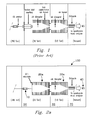
- FIG. 1 illustrates an electrospray ionization/mass spectrometer (ESI/MS) instrument configuration of a conventional design.
- an atmospheric pressure electrospray ionization (ESI) source with an ES emitter couples to an ion funnel positioned in a low pressure (e.g., 18 Torr) region via a heated inlet capillary interface. Ions formed from electrospray at atmospheric pressure are introduced into the low pressure region through the capillary inlet and focused by the first ion funnel.
- a second ion funnel operating at a lower pressure (e.g., 2 Torr) than the first ion funnel operating pressure provides further focusing of ions prior to their introduction into a mass analyzer.
- the present invention is an electrospray ionization source that is characterized by a first vacuum chamber enclosing both an ESI transmitter and a feed line for a supply gas.
- the first vacuum chamber has an exit orifice positioned at an entrance to a first ion guide that is enclosed in a second vacuum chamber.
- a sample comprising electrospray ions is transmitted from the ESI transmitter to the ion guide through the exit orifice.
- Embodiments of the present invention provide improved ion transmission because the ESI transmitter and the ion guide are each operated at more optimal pressures without the extreme loss of ions typically associated with traditional capillary inlets.
- the pressure in the first vacuum chamber is at least two times greater than that of the second vacuum chamber.
- the pressure in the first chamber can be at least 50 Pascals (or Torr) and the pressure in the second chamber can be at most 30 Pascals (Torr).
- a pump can be used to maintain a vacuum in the first and second vacuum chambers, wherein a pressure differential can be established between the two vacuum chambers by a flow of supply gas in the first chamber and by the exit orifice, which has a limited conductance.
- the orifice can have a diameter between approximately 2 mm and 5 mm.
- the ESI source (as consistent with the embodiments described and claimed herein) can transmit at least 50% of the electrospray current from the ESI transmitter to the ion guide. This is a significant improvement over traditional ESI sources.
- Preferred embodiments employ a chamber heating element that provides control of the temperature in the first vacuum chamber, which can improve desolvation.
- the ESI transmitter can comprise a single emitter or a plurality of emitters.
- the ion guide can include, but are not limited to, an electrodynamic ion funnel or a multi-pole ion guide which may have a receiving aperture and a relatively smaller exit aperture.
- the multi-pole ion guide can comprise 2n poles, where n is an integer greater than or equal to 2.
- the multi-pole ion guide can be a segmented multi-pole ion guide.
- the flow rate of the supply gas can be regulated by a controller operably attached to a feed line.
- the supply gas comprises an electron scavenger that can reduce the electrical breakdown in the first vacuum chamber.
- Exemplary electron scavengers can include, but are not limited to CO 2 and SF 6 .
- FIG. 1 (Prior Art) illustrates an ESI/MS instrument configuration of a conventional design.
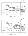
- FIGs. 2a to 2d illustrate various embodiments of the present invention.
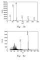
- FIGs. 3a and 3b present mass spectra resulting from a calibration solution infused (a) through a conventional atmospheric pressure ESI emitter and heated inlet capillary interface, and (b) through a low pressure ESI emitter of the invention.
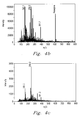
- FIGs. 4a and 4c present mass spectra resulting from a reserpine solution (a) infused through a conventional atmospheric pressure ESI emitter and heated inlet capillary interface, (b) infused through a low pressure ESI emitter of the invention, and (c) analyzed with RF voltage to a first ion funnel turned off.
- FIG. 5 plots ES current across an ion plume as a function of different ES chamber pressures.
- FIG. 6 plots peak intensity as a function of RF voltage for a reserpine solution analyzed with the preferred embodiment of the invention.
- FIG. 7 plots peak intensity as a function of flow rate at fixed RF voltage for a reserpine solution, analyzed with the preferred embodiment of the invention.
- FIG. 8 plots transmission curves for leucine, enkephalin, reserpine, bradykinin and ubiquitin ions as a function of pressure, analyzed with the preferred embodiment of the invention.
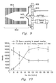
- FIG. 9 is an illustration depicting an ESI source according to one embodiment of the present invention.
- FIG. 10 is a plot of peak intensities at different electrospray flow rates for peptide ions using the embodiment depicted in the Fig. 9 compared to a conventional ESI-MS ion source design.
- FIGS. 11a and 11b compare the mass spectra obtained using the embodiment depicted in the Fig. 9 and a conventional ESI-MS ion source design.
- FIG. 2a illustrates an instrument system 100 of the invention incorporating a preferred embodiment of an ESI source emitter 10.
- ES emitter (transmitter) 10 is shown positioned in a direct relationship with a first ion guide 20a, in this case an electrodynamic ion funnel 20a, via a receiving (entrance) aperture, in this case the first electrode of the electrodynamic ion funnel.
- ES emitter 10 was placed inside a first vacuum region 50 and positioned at the entrance of the first electrodynamic ion funnel, allowing the entire ES plume to be sampled by (i.e., transmitted directly to or within) the ion funnel.
- a second ion funnel 30a is shown within a second reduced pressure region or environment 60 to effect ion focusing prior to introduction to the vacuum region 70 of a mass selective analyzer 40.
- the second ion funnel is coupled to the first ion funnel.
- mass spectrometer 40 is preferably a single quadrupole mass spectrometer, but is not limited thereto.
- First ion funnel 20a had a lower capacitance than second ion funnel 30a, as described, e.g., by Wheat et al. (in J. Am. Soc. Mass Spectrom. 2006, 17, 1299-1305 , incorporated herein in its entirety), but is not limited thereto.
- the low capacitance ion funnel permits use of higher frequency and amplitude RF voltage to effect capture and transmission of the ES ion plume for desolvation of the analyte ions at higher relative pressure compared to pressure in second ion funnel chamber 60.
- Transmission of ions in the ion plume from emitter 10 to first ion funnel 20a, to second ion funnel 30a, and ultimately to vacuum 70 of mass analyzer 40 occurs with low ion losses.
- transmission of ions in the ion plume proceeds at efficiencies or quantities up to 100%.
- results from test experiments demonstrated ion losses were significantly reduced compared to a conventional atmospheric pressure ESI source and heated capillary interface.
- stable electrosprays were achieved at pressures down to at least about 25 Torr in pressure region 50.
- pressures described in conjunction with the instant embodiment are not necessarily to be considered limiting.
- pressures may be selected below atmospheric pressure. More particularly, pressures may be selected in the range from about 100 Pa (Torr) to about 1 Pa (Torr). Most particularly, pressures may be selected below about 30 Pa (Torr).
- the emitter can be a multiemitter, e.g., as an array of emitters.
- Fig. 2b illustrates an instrument system 200, according to another embodiment of the invention.
- the second ion funnel FIG. 2a
- the second ion funnel FIG. 2a
- the pressures e.g. in regions 50, 60, and 70
- Multipole ion guide 30b can include (2 ⁇ n) poles to effectively focus and transmit ions into MS 40, where n is an integer greater than or equal to 2. No limitations are intended.
- FIG. 2c illustrates an instrument system 300, according to yet another embodiment of the invention.
- the first ion funnel FIG. 2a
- an RF multipole ion guide 20c which can include (2 ⁇ n) poles to effectively focus and transmit ions into second ion funnel 30c, where n is any integer greater than 1.
- each pole in the multipole ion guide 20c can be tilted with a uniform or non uniform angle to create a larger entrance aperture facing the ES plume, and a smaller exit aperture into the second ion funnel.
- Other illustrated components emitter 10 and MS 40
- pressures e.g. in regions 50, 60, and 70 are identical to those previously described in reference to FIG. 2a .
- FIG. 2d illustrates an instrument system 400 according to still yet another embodiment of the invention.
- both the first ion funnel and the second ion funnel ( FIG. 2a ) described previously are replaced by two RF multipole ion guides 20d and 30d, respectively.
- Multipole ion guides 20d and 30d can include (2 ⁇ n) poles to effectively focus and transmit ions, where n is any integer greater than 1.
- Each pole in multipole ion guide 20d can be tilted with a uniform or non uniform angle to create a larger entrance aperture facing the ES plume, and a smaller exit aperture.
- Other illustrated components (emitter 10 and MS 40) and pressures (e.g. in regions 50, 60, and 70) are identical to those previously described in reference to FIG.
- multipole ion guides described herein can be further replaced with segmented multipole ion guides.
- An electric field along the axis of the selected ion guide can be created by applying a DC potential gradient to different segments of the ion guide to rapidly push ions through the ion guide.
- emitter 10 was a chemically etched capillary emitter, prepared as described by Kelly et al. (in Anal. Chem. 2006, 78, 7796-7801 ) from 10 ⁇ m I.D., 150 ⁇ m O.D. fused silica capillary tubing (Polymicro Technologies, Phoenix, AZ, USA).
- the ES emitter was coupled to a transfer capillary and a 100 ⁇ L syringe (Hamilton, Las Vegas, NV, USA) by a stainless steel union, which also served as the connection point for the ES voltage.
- Analyte solutions were infused from a syringe pump (e.g., a model 22 syringe pump, Harvard Apparatus, Inc., Holliston, MA, USA). Voltages were applied to the ES emitter via a high voltage power supply (e.g., a Bertan model 205B-03R high voltage power supply, Hicksville, NY, USA). A CCD camera with a microscope lens (Edmund Optics, Barrington, NJ) was used to observe the ES. Placement of the ES emitter was controlled by a mechanical vacuum feedthrough (Newport Corp., Irvine, CA, USA). A stainless steel chamber was constructed to accommodate placement of the ES emitter at the entrance of the first ion funnel.
- a syringe pump e.g., a model 22 syringe pump, Harvard Apparatus, Inc., Holliston, MA, USA.
- Voltages were applied to the ES emitter via a high voltage power supply (e.g.,
- the chamber used three glass windows, one at the top of the chamber, and one on each side of the chamber that allowed proper lighting for visual observation of the ES by the CCD camera.
- An ion funnel consisting of seventy (70) electrodes was used to allow the ES emitter to be observed through the viewing windows.
- a grid electrode FIG. 2a
- the ES emitter was placed -5 mm in front of the grid electrode and centered on axis with the ion funnel.
- the vacuum chamber contained feedthroughs for the ES voltage, an infusion capillary, and a gas line controlled by a leak valve to room air.
- a rough pump e.g., a model E1M18 pump, BOC Edwards, Wilmington, MA, USA
- the pumping speed was regulated by an in-line valve.
- a gate valve was built into the first ion funnel and was located between the last ion funnel RF/DC electrode plate and the conductance limiting orifice plate, allowing ES chamber venting and ES emitter maintenance without having to vent the entire mass spectrometer.
- the gate valve was constructed from a small strip of 0.5 mm thick TEFLON®, which was placed between the last ion funnel electrode and the conductance limiting orifice electrode and attached to an in-house built mechanical feedthrough, which moved the TEFLON® over the conductance limiting orifice during venting of the ES chamber.
- a conventional configuration FIG. 1
- the atmospheric pressure ESI source and ES emitter were controlled using a standard X-Y stage (e.g., a Model 433 translation stage, Newport Corp., Irvine, CA, USA).
- a low capacitance ion funnel e.g., as described by Y. Ibrahim et al. (in J. Am. Soc. Mass Spectrom. 2006, 17, 1299-1305 , incorporated herein in its entirety) was used that could be effectively operated at higher pressure.
- both the funnel RF frequency and amplitude were raised from typical operating frequencies and amplitudes of 550 kHz and 80 V p-p to 1.3 MHz and 175 V p-p , respectively.
- the first ion funnel consisted of 100, 0.5 mm thick ring electrode plates separated by 0.5 mm thick TEFLON® insulators.
- a front straight section of the ion funnel consisted of 58 electrodes with a 25.4 mm I.D.
- the tapered section of the ion funnel included 42 electrodes that linearly decreased in I.D., beginning at 25.4 mm and ending at 2.5 mm.
- the last electrode plate was a DC-only conductance limiting orifice with a 1.5 mm I.D. biased to 210 V. Excess metal was removed from the electrode plates to reduce capacitance, enabling greater RF frequencies and voltages.
- the first ion funnel was otherwise identical to that in test configuration FIG. 1 except that 30 funnel electrodes were removed from the straight section, leaving a total of 28 electrodes with a 25.4 mm I.D. in the straight section of the ion funnel. A 1.3 MHz RF with an amplitude of 350 V p-p was used. No jet disrupter was used for the first ion funnel in the test configuration of FIG. 2a .
- FIG. 1 and FIG. 2a had the same DC voltage gradient of 18.5 V/cm.
- the second ion funnel was identical to the first ion funnel in FIG. 1 and used in a subsequent vacuum region for both the test configurations of FIG. 1 and FIG. 2a .
- a 740 kHz RF with amplitude of 70 V p-p was applied to the second ion funnel along with a DC voltage gradient of 18.5 V/cm.
- the jet disrupter and 2.0 mm I.D. conductance limiting orifice were biased to 170 V and 5 V, respectively.
- An Agilent MSD1100 (Santa Clara, CA) single quadrupole mass spectrometer was coupled to the dual ion funnel interface, and ultimately to the ESI ion source and emitter. Mass spectra were acquired with a 0.1 m / z step size. Each spectrum was produced from an average of 10 scans to reduce effects of any intensity fluctuations in the ES.
- a linear array of (23) electrodes was incorporated into the front section of a heated capillary assembly, described, e.g., by J.S. Page et al. (in J. Am. Soc. Mass Spectrom. 2007, in press ) to profile the ES current lost on the front surface of the entrance aperture at various ES chamber pressures.
- a 490 ⁇ m id, 6.4 cm long, stainless steel capillary was silver soldered in the center of a stainless steel body. Metal immediately below the entrance aperture was removed and a small stainless steel vice was constructed on the entrance aperture to press 23 KAPTON®-coated 340 ⁇ m O.D. copper wires in a line directly below the aperture entrance.
- the front of the entrance aperture was machined flat and polished with 2000 grit sandpaper (Norton Abrasives, Worcester, MA) making the ends of the wires an array of round, electrically isolated electrodes each with diameter of 340 ⁇ m.
- the other ends of the wires were connected to an electrical breadboard with one connection to common ground and another to a picoammeter (e.g., a Keithley model 6485 picoammeter, Keithley, Cleveland, OH) referenced to ground.
- the electrode array was used as the inlet to the single quadrupole mass spectrometer and installed inside the ES vacuum chamber.
- ES current was profiled by sequentially detecting current on all 23 electrodes by selecting and manually moving the appropriate wire from the common ground output to the picoammeter input and acquiring 100 consecutive measurements. Measurements were averaged using the data acquisition capabilities of the picoammeter.
- the low pressure ESI source and emitter of the preferred embodiment of the invention was tested by analyzing 1) a calibration (calibrant) solution (Product No. G2421A, Agilent Technologies, Santa Clara, CA, USA) containing a mixture of betaine and substituted triazatriphosphorines dissolved in acetonitrile and 2) a reserpine solution (Sigma-Aldrich, St. Louis, MO, USA).
- a methanol:water solvent mixture for ESI was prepared by combining purified water (Barnstead Nanopure Infinity system, Dubuque, IA) with methanol (HPLC grade, Fisher Scientific, Fair Lawn, NJ, USA) in a 1:1 ratio and adding acetic acid (Sigma-Aldrich, St.
- FIGs. 4a-4c present mass spectra obtained with respective instrument configurations from analyses of a 1 ⁇ M reserpine solution infused at 300 nL/min.
- the spectrum was acquired with RF voltage to the first ion funnel turned off, which greatly reduced ion transmission and showed utility of the ion guide in the preferred embodiment of the invention.
- FIG. 4b A comparison of results from analysis of the calibration solution using the test configuration with the low pressure ESI source of the preferred embodiment of the invention ( FIG. 2a ) and the conventional atmospheric ESI ( FIG. 1 ) in FIGs. 3a and 3b showed a 4- to 5-fold improvement in sensitivity when ES was performed using the low pressure ESI source.
- FIG. 4b a sensitivity increase of - 3 fold for reserpine is obtained over that obtained in FIG. 4a .
- the emitter was positioned so that the ion/charged droplet plume was electrosprayed directly into the first ion funnel. Both the emitter and ion funnel were in a 25 Torr pressure environment.
- Results indicate that removing the conventional capillary inlet and electrospraying directly into an ion funnel can decrease analyte loss in an ESI interface.
- turning off the RF voltage of the first ion funnel eliminates ion focusing in this (ion funnel) stage, greatly reducing focusing and thus transmission of ions to subsequent stages and to the mass spectrometer.
- Results demonstrate need for the ion funnel, which effectively transmits ES current into the second ion funnel.
- the ES current was profiled at various chamber pressures using a linear array of charge collectors positioned on the mass spectrometer inlet. Pressures ranged from atmospheric pressure (e.g., 760 Torr) to 25 Torr. Current was measured using a special counter electrode array positioned 3 mm from the ESI emitter, which provided a profile, or slice, of the ES current at the center of the ion/charged droplet plume.
- the solvent mixture electrosprayed by the ESI emitter consisted of a 50:50 methanol:water solution with 1% v/v acetic acid, which was infused to the ES emitter at a flow rate of 300 nL/min.
- FIG. 5 plots the radial electric current distribution of the electrospray plume as a function of pressure.
- ESI current of 42 nA was achieved at the selected (300 nL/min) flow rate, which can be maintained in a broad range of pressures by simply adjusting the spray voltage.
- a well behaved electrospray is evident for pressures as low as 25 Torr. Higher pressures produced a plume that was ⁇ 5 mm wide. At 100 Torr and 50 Torr, the plume narrowed slightly with an increase ES current density and this was more pronounced at 25 Torr. ES flow rate, voltage, and current changed minimally as pressure was lowered. Decrease in the spray plume angle at lower pressures may be a consequence of narrower ion/droplet plumes detected by the electrode array.
- Results are attributed to an increase in electrical mobility as a result of an increase in mean-free-path, described, e.g., by Gamero-Castano et al. (in J. Appl. Phys. 1998, 83, 2428-2434 ).
- Another observation was the independence of the electrospray (ES) on pressure, which has been described, e.g., Aguirre-de-Carcer et al. (in J. Colloid Interface Sci. 1995, 171, 512-517 ).
- Profiling of the ES current detected the charge distribution across the ion/charged droplet plume, but did not provide information on the creation (ionization) of liberated, gas-phase, ions, i.e., the "ionization efficiency”. Ionization efficiency is described further hereafter.
- the low pressure ES source was coupled to a single quadrupole mass spectrometer.
- Baseline measurements of a reserpine and calibration solution prepared as in Example 1 were first acquired using a standard atmospheric ESI source with a heated metal inlet capillary ( FIG. 1 ).
- the test configuration used two ion funnels. The front ion funnel operated at 18 Torr; back ion funnel operated at 2 Torr. Similar transmission efficiencies were obtained to those described, e.g., (2004), et al. (in J. Am. Soc. Mass Spectr. 2006, 17, 1299-1305 ) for single ion funnel interfaces, while allowing a much larger sampling efficiency (i.e., inlet conductance).
- FIG. 6 is a plot of reserpine intensity versus the amplitude of RF voltage applied to the first ion funnel. In the figure, error bars indicate the variance in three replicate measurements.
- Increasing voltage also increases the effective potential of the ion funnel, which may provide better focusing of droplets and larger clusters contributing to increased sensitivity.
- the first ion funnel can be used as a desolvation stage for removing solvent from analytes of interest.
- Desolvation may be further promoted, e.g., in conjunction with heating of the emitter and/or other instrument components using a coupled heat source, including, but not limited to, e.g., heated gases and sources, radiation heat sources, RF heat sources, microwave heat sources, radiation heat sources, inductive heat sources, heat tape, and the like, and combinations thereof. Additional components may likewise be used as will be selected by those of skill in the art.
- FIG. 7 plots peak intensity for reserpine, with error bars corresponding to three replicate measurements. In the figure, peak intensity decreases initially as flow rate is lowered from 500 nL/min to 300 nL/min, and begins to decrease more slowly at the lower flow rates.
- Results indicate that even though less reserpine is delivered to the ES emitter at lower flow rates, a greater percentage of reserpine is converted to liberated ions. Results demonstrate 1) that the ion funnel effectively desolvates smaller droplets, and 2) that improved desolvation is needed at higher flow rates.
- ES droplet size correlates with the flow rate, as described, e.g., by Wilm et al. (in Int J. Mass Spectrom. Ion Processes 1994, 136, 167-180 ) and Fernandez de la Mora et al. (in J. Fluid Mech. 1994, 155-184 ). Smaller flow rates thus create smaller droplets, and smaller droplets require less desolvation and fission events to produce liberated analyte ions.
- Transmission efficiency of ions in an ion funnel was tested as a function of pressure by analyzing ions having different mass-to-charge ratios. Ions included Leucine, Enkephalin, Reserpine, Bradykinin, and Ubiquitin.
- the first ion funnel was operated with RF 1.74 MHz and amplitude ranging from 40 to 170 V p-p .
- the second ion funnel was operated at RF 560 kHz and 70 V p-p .
- FIG. 8 presents experimental results.
- data for Bradykinin represent the sum of 2+ charge states.
- Data for Ubiquitin represent the sum of charge states up to 12+.
- Ion transmission efficiency remains approximately constant up to a 30 Torr pressure maximum.
- Overlapping operating pressure between the low pressure electrospray and the high pressure ion funnel makes it possible to couple them directly without the need of an inlet orifice/capillary.
- Results demonstrate that stable electrospray can be maintained at pressures as low as 25 Torr and that good ion transmission can be obtained in the high pressure ion funnel at pressures as high as 30 Torr. Overlap between the two pressures indicates that the concept of interfaceless ion transmission in the instrument is practical.
- results further indicate that biological analyses in conjunction with the invention are conceivable and may ultimately prove to be an enabling technology applicable to high-throughput proteomics analyses.
- the invention could thus prove to be a significant breakthrough in reducing ion losses from electrospray ionization, which along with MALDI, is a prevalent form of ionizing biological samples for analysis by mass spectrometry.
- Results presented herein are an initial demonstration of an ESI source/ion funnel combination for producing and transmitting ions in a low pressure (e.g., 25 Torr) environment for use in MS instruments.
- Use of the ion funnel or other alternatives as illustrated in FIG. 2 is critical to the success of the low pressure ESI source.
- a large (-2.5 cm), entrance I.D. provides sufficient acceptance area for an entire ES plume to be sampled into the ion funnel device.
- the length of the ion funnel and the RF field employed therein provide a region for desolvation prior to transmission into the mass spectrometer. Sensitivity gains were observed for all solutions analyzed.
- the electrospray transmitter is positioned in a direct relationship with a receiving aperture of a first ion guide. Furthermore, the electrospray transmitter and the first ion guide are positioned together in a single vacuum region. However, in a more preferred embodiment, the ESI transmitter and the first ion guide are operated at different pressures.
- a first vacuum chamber 901 encloses both an ESI emitter 903 and a feedline 905 for a supply gas.
- the first vacuum chamber has an exit orifice 906 through which electrospray ions can be transmitted to the entrance of an ion funnel 904 that is positioned in a second vacuum chamber 902.
- a pump can maintain a base vacuum in both the first and second vacuum chambers while a pressure differential can be established between the two chambers based on the amount of supply gas admitted into the first vacuum chamber and on the size of the exit orifice, which has a limited conductance.
- the positioning of the ESI transmitter with respect to the exit orifice at the entrance of the ion funnel maximizes ion transmission from the ESI emitter into the ion funnel, thereby avoiding the problems that are common among configurations taught in the prior art (e.g., see FIG. 1 ).
- Figs. 10 and 11 Experimental data obtained using the embodiment illustrated in Fig. 9 and described elsewhere herein are shown in Figs. 10 and 11 .
- the pressure of the first vacuum chamber containing the ESI emitter was 50 Torr.
- the pressure of the second vacuum chamber containing the first ion guide was 25 Torr.
- Fig. 10 plots the MS signal from a peptide analysis versus flow rate. The signal from the peptide improves with lower flow rates when the embodiment in Figure 9 is used compared with a conventional ESI source.
- An additional benefit of the Figure 9 embodiment is shown in Fig. 11 , where mass spectra from the analysis of a five peptide solution are displayed using a conventional ESI source (11a) and the Figure 9 embodiment (11b).
- an electrospray ionization (ESI) source characterized by a first vacuum chamber enclosing both an ESI transmitter and a feed line for a supply gas, the first vacuum chamber having an exit orifice positioned at an entrance to a first ion guide enclosed in a second vacuum chamber.
- the arrangement is such that a sample comprising electrospray ions may be transmitted from the ESI transmitter to the ion guide through the exit orifice.
- the ESI transmitter may comprise a plurality of emitters.
- the ion guide may be an electrodynamic ion funnel.
- the ion guide may be a multi-pole ion guide, which preferably has a receiving aperture and a relatively smaller exit aperture.
- the multi-pole ion guide may comprise 2n poles, where n is an integer greater than or equal to 2.
- the multi-pole ion guide may be a segmented multi-pole ion guide.
- the pressure in the first chamber is preferably at least 50 Pa.
- the pressure in the second chamber is preferably is at most 30 Pa.
- the pressure in the first vacuum chamber is preferably at least two times greater than that in the second vacuum chamber.
- the ESI source may further comprise a pump for maintaining a vacuum in the first and the second vacuum chambers.
- a pressure differential may be established between the first and the second vacuum chambers at least in part by the supply gas and the exit orifice, which typically has a limited conductance thereby providing the differential.
- the exit orifice may typically have a diameter of between 2 mm and 5 mm.
- At least 50% of the electrospray current is transmitted from the ESI transmitter to the ion guide.
- the ESI source may further comprise a chamber heating element which serves to provide means for controlling of the temperature in the first vacuum chamber.
- the supply gas comprises preferably comprises an electron scavenger that reduces the electrical breakdown in the first vacuum chamber.
- the supply gas may be, or may comprise, CO 2 , SF 6 or a mixture of both.
- the ESI source may further comprise a controller for regulating the supply gas flow.
- the ESI source may further comprise a second ion guide positioned downstream of the first ion guide.
- the second ion guide may be positioned in a third vacuum region, which third region preferably has a pressure less than that of the second vacuum region.
- the invention provides the use of an ESI source as hereinbefore described as an ESI source in a mass spectrometer.
- an electrospray ionization (ESI) source is characterized by a first vacuum chamber enclosing both an ESI transmitter and a feed line for a supply gas, the first vacuum chamber having an exit orifice positioned at an entrance to a first ion guide enclosed in a second vacuum chamber, wherein a sample comprising electrospray ions is transmitted from the ESI transmitter to the ion guide through the exit orifice.
- ESI electrospray ionization
- An "interfaceless" electrospray ionization system is further described that operates an electrospray at a reduced pressure such that standard electrospray sample solutions can be directly sprayed into an electrodynamic ion funnel which provides ion focusing and transmission of ions into a mass analyzer. Furthermore, chambers maintained at different pressures can allow for more optimal operating conditions for an electrospray emitter and an ion guide.
Landscapes
- Chemical & Material Sciences (AREA)
- Analytical Chemistry (AREA)
- Physics & Mathematics (AREA)
- Engineering & Computer Science (AREA)
- Plasma & Fusion (AREA)
- Other Investigation Or Analysis Of Materials By Electrical Means (AREA)
- Electron Tubes For Measurement (AREA)
Abstract
Description
- This invention was made with U.S. Government support under Contract DE-AC05-76RLO1830 awarded by the U.S. Department of Energy. The Government has certain rights in the invention.
- This invention claims priority from
US patent application 12/468,645 filed on 19 May 2009US 2009/0242755A1 . - The present invention relates generally to analytical instrumentation and more particularly to a low pressure electrospray ionization system and process for effective transmission of ions between coupled ion stages with low ion losses.
- Achieving high sensitivity in mass spectrometry (MS) is key to effective analysis of complex chemical and biological samples. Every significant improvement in MS detection limits will enable applications that were previously impractical. Advances in MS sensitivity can also increase the dynamic range over which quantitative measurements can be performed.
-
FIG. 1 illustrates an electrospray ionization/mass spectrometer (ESI/MS) instrument configuration of a conventional design. In the figure, an atmospheric pressure electrospray ionization (ESI) source with an ES emitter couples to an ion funnel positioned in a low pressure (e.g., 18 Torr) region via a heated inlet capillary interface. Ions formed from electrospray at atmospheric pressure are introduced into the low pressure region through the capillary inlet and focused by the first ion funnel. A second ion funnel operating at a lower pressure (e.g., 2 Torr) than the first ion funnel operating pressure provides further focusing of ions prior to their introduction into a mass analyzer. - It well known in the art that sensitivity losses in ESI/MS are pronounced at the interface between the atmospheric pressure region and the low pressure region. Ion transmission through conventional interfaces is essentially limited by small MS sampling inlets--typically between 400 µm to 600 µm in diameter--required to maintain a good vacuum pressure in the MS analyzer. Sampling inlets can account for up to 99% of ion losses in the interface region, providing less than about 1% overall ion transmission efficiency. Accordingly, new systems, devices, and methods are needed to effectively eliminate the major ion losses in interface regions, e.g., between atmospheric ion source stage and a subsequent low pressure stage important to sensitive ion analyses.
- The present invention is an electrospray ionization source that is characterized by a first vacuum chamber enclosing both an ESI transmitter and a feed line for a supply gas. The first vacuum chamber has an exit orifice positioned at an entrance to a first ion guide that is enclosed in a second vacuum chamber. A sample comprising electrospray ions is transmitted from the ESI transmitter to the ion guide through the exit orifice. Embodiments of the present invention provide improved ion transmission because the ESI transmitter and the ion guide are each operated at more optimal pressures without the extreme loss of ions typically associated with traditional capillary inlets.
- In a preferred aspect of the invention, the pressure in the first vacuum chamber is at least two times greater than that of the second vacuum chamber. For example, the pressure in the first chamber can be at least 50 Pascals (or Torr) and the pressure in the second chamber can be at most 30 Pascals (Torr).
- According to one implementation a pump can be used to maintain a vacuum in the first and second vacuum chambers, wherein a pressure differential can be established between the two vacuum chambers by a flow of supply gas in the first chamber and by the exit orifice, which has a limited conductance. In some embodiments, the orifice can have a diameter between approximately 2 mm and 5 mm.
- The ESI source (as consistent with the embodiments described and claimed herein) can transmit at least 50% of the electrospray current from the ESI transmitter to the ion guide. This is a significant improvement over traditional ESI sources.
- Preferred embodiments employ a chamber heating element that provides control of the temperature in the first vacuum chamber, which can improve desolvation.
- The ESI transmitter can comprise a single emitter or a plurality of emitters. Specific examples of the ion guide can include, but are not limited to, an electrodynamic ion funnel or a multi-pole ion guide which may have a receiving aperture and a relatively smaller exit aperture. The multi-pole ion guide can comprise 2n poles, where n is an integer greater than or equal to 2. Alternatively, the multi-pole ion guide can be a segmented multi-pole ion guide. The flow rate of the supply gas can be regulated by a controller operably attached to a feed line. In a preferred embodiment, the supply gas comprises an electron scavenger that can reduce the electrical breakdown in the first vacuum chamber. Exemplary electron scavengers can include, but are not limited to CO2 and SF6.
- The purpose of the foregoing summary of the invention is to enable the public generally, especially the scientists, engineers, and practitioners in the art who are not familiar with patent or legal terms or phraseology, to determine quickly from a cursory inspection the nature and essence of the technical disclosure of the application.
- Various advantages and novel features of the present invention are described herein and will become further readily apparent to those skilled in this art from the following detailed description. In the preceding and following descriptions, the various embodiments, including the preferred embodiments, have been shown and described. Included herein is a description of the best mode contemplated for carrying out the invention. As will be realized, the invention is capable of modification in various respects without departing from the invention as defined in the claims. Accordingly, the drawings and description of the preferred embodiments set forth hereafter are to be regarded as illustrative in nature, and not as restrictive.
-
FIG. 1 (Prior Art) illustrates an ESI/MS instrument configuration of a conventional design. -
FIGs. 2a to 2d illustrate various embodiments of the present invention. -
FIGs. 3a and3b present mass spectra resulting from a calibration solution infused (a) through a conventional atmospheric pressure ESI emitter and heated inlet capillary interface, and (b) through a low pressure ESI emitter of the invention. -
FIGs. 4a and4c present mass spectra resulting from a reserpine solution (a) infused through a conventional atmospheric pressure ESI emitter and heated inlet capillary interface, (b) infused through a low pressure ESI emitter of the invention, and (c) analyzed with RF voltage to a first ion funnel turned off. -
FIG. 5 plots ES current across an ion plume as a function of different ES chamber pressures. -
FIG. 6 plots peak intensity as a function of RF voltage for a reserpine solution analyzed with the preferred embodiment of the invention. -
FIG. 7 plots peak intensity as a function of flow rate at fixed RF voltage for a reserpine solution, analyzed with the preferred embodiment of the invention. -
FIG. 8 plots transmission curves for leucine, enkephalin, reserpine, bradykinin and ubiquitin ions as a function of pressure, analyzed with the preferred embodiment of the invention. -
FIG. 9 is an illustration depicting an ESI source according to one embodiment of the present invention. -
FIG. 10 is a plot of peak intensities at different electrospray flow rates for peptide ions using the embodiment depicted in theFig. 9 compared to a conventional ESI-MS ion source design. -
FIGS. 11a and 11b compare the mass spectra obtained using the embodiment depicted in theFig. 9 and a conventional ESI-MS ion source design. - While the present disclosure is exemplified by a description of the preferred embodiments, it should be understood that the invention is not limited thereto, and variations in form and detail may be made without departing from the scope of the invention. All modifications as would be envisioned by those of skill in the art in view of the disclosure permissible provided they fall within the scope of the invention as defined by the claims hereinafter. In particular in prosecuting this application technical features or parameters or components may be isolated from their context and imported into the claims so as to more specifically define the scope of protection sought.
-
FIG. 2a illustrates aninstrument system 100 of the invention incorporating a preferred embodiment of anESI source emitter 10. ES emitter (transmitter) 10 is shown positioned in a direct relationship with afirst ion guide 20a, in this case anelectrodynamic ion funnel 20a, via a receiving (entrance) aperture, in this case the first electrode of the electrodynamic ion funnel.ES emitter 10 was placed inside afirst vacuum region 50 and positioned at the entrance of the first electrodynamic ion funnel, allowing the entire ES plume to be sampled by (i.e., transmitted directly to or within) the ion funnel. Asecond ion funnel 30a is shown within a second reduced pressure region orenvironment 60 to effect ion focusing prior to introduction to thevacuum region 70 of a massselective analyzer 40. The second ion funnel is coupled to the first ion funnel. In the instant configuration,mass spectrometer 40 is preferably a single quadrupole mass spectrometer, but is not limited thereto.First ion funnel 20a had a lower capacitance thansecond ion funnel 30a, as described, e.g., by Ibrahim et al. (in J. Am. Soc. Mass Spectrom. 2006, 17, 1299-1305, incorporated herein in its entirety), but is not limited thereto. The low capacitance ion funnel permits use of higher frequency and amplitude RF voltage to effect capture and transmission of the ES ion plume for desolvation of the analyte ions at higher relative pressure compared to pressure in secondion funnel chamber 60. Transmission of ions in the ion plume fromemitter 10 tofirst ion funnel 20a, tosecond ion funnel 30a, and ultimately to vacuum 70 ofmass analyzer 40 occurs with low ion losses. In particular, transmission of ions in the ion plume proceeds at efficiencies or quantities up to 100%. And, results from test experiments demonstrated ion losses were significantly reduced compared to a conventional atmospheric pressure ESI source and heated capillary interface. Experiments further demonstrated that stable electrosprays were achieved at pressures down to at least about 25 Torr inpressure region 50. - Pressures described in conjunction with the instant embodiment are not necessarily to be considered limiting. In particular, pressures may be selected below atmospheric pressure. More particularly, pressures may be selected in the range from about 100 Pa (Torr) to about 1 Pa (Torr). Most particularly, pressures may be selected below about 30 Pa (Torr).
- While the instant embodiment has been described with reference to a single ES emitter, the invention is not limited thereto. For example, the emitter can be a multiemitter, e.g., as an array of emitters.
-
Fig. 2b illustrates aninstrument system 200, according to another embodiment of the invention. In the instant configuration, the second ion funnel (FIG. 2a ) is replaced by (exchanged with) an RFmultipole ion guide 30b. Here, other illustrated components (emitter 10 andfirst ion funnel 20b) and pressures (e.g. inregions FIG. 2a , but should not be considered limiting.Multipole ion guide 30b can include (2·n) poles to effectively focus and transmit ions intoMS 40, where n is an integer greater than or equal to 2. No limitations are intended. -
FIG. 2c illustrates aninstrument system 300, according to yet another embodiment of the invention. Insystem 300, the first ion funnel (FIG. 2a ) is replaced by an RFmultipole ion guide 20c, which can include (2·n) poles to effectively focus and transmit ions intosecond ion funnel 30c, where n is any integer greater than 1. To effectively capture the ES plume, each pole in themultipole ion guide 20c can be tilted with a uniform or non uniform angle to create a larger entrance aperture facing the ES plume, and a smaller exit aperture into the second ion funnel. Other illustrated components (emitter 10 and MS 40) and pressures (e.g. inregions FIG. 2a . -
FIG. 2d illustrates aninstrument system 400 according to still yet another embodiment of the invention. In the instant system, both the first ion funnel and the second ion funnel (FIG. 2a ) described previously are replaced by two RF multipole ion guides 20d and 30d, respectively. Multipole ion guides 20d and 30d can include (2·n) poles to effectively focus and transmit ions, where n is any integer greater than 1. Each pole inmultipole ion guide 20d can be tilted with a uniform or non uniform angle to create a larger entrance aperture facing the ES plume, and a smaller exit aperture. Other illustrated components (emitter 10 and MS 40) and pressures (e.g. inregions FIG. 2a . As will be understood by those of skill in the art, multipole ion guides described herein can be further replaced with segmented multipole ion guides. Thus, no limitations should be necessarily interpreted by the description to present components. An electric field along the axis of the selected ion guide can be created by applying a DC potential gradient to different segments of the ion guide to rapidly push ions through the ion guide. - In a test configuration of the preferred embodiment of the invention (
FIG. 2a ),emitter 10 was a chemically etched capillary emitter, prepared as described by Kelly et al. (in Anal. Chem. 2006, 78, 7796-7801) from 10 µm I.D., 150 µm O.D. fused silica capillary tubing (Polymicro Technologies, Phoenix, AZ, USA). The ES emitter was coupled to a transfer capillary and a 100 µL syringe (Hamilton, Las Vegas, NV, USA) by a stainless steel union, which also served as the connection point for the ES voltage. Analyte solutions were infused from a syringe pump (e.g., a model 22 syringe pump, Harvard Apparatus, Inc., Holliston, MA, USA). Voltages were applied to the ES emitter via a high voltage power supply (e.g., a Bertan model 205B-03R high voltage power supply, Hicksville, NY, USA). A CCD camera with a microscope lens (Edmund Optics, Barrington, NJ) was used to observe the ES. Placement of the ES emitter was controlled by a mechanical vacuum feedthrough (Newport Corp., Irvine, CA, USA). A stainless steel chamber was constructed to accommodate placement of the ES emitter at the entrance of the first ion funnel. The chamber used three glass windows, one at the top of the chamber, and one on each side of the chamber that allowed proper lighting for visual observation of the ES by the CCD camera. An ion funnel consisting of seventy (70) electrodes was used to allow the ES emitter to be observed through the viewing windows. A grid electrode (FIG. 2a ) was made from a -8 line-per-cm mesh rated at 93.1% transmission and placed 0.5 mm in front of the first ion funnel as a counter electrode for the ES, biased to 450 V. The ES emitter was placed -5 mm in front of the grid electrode and centered on axis with the ion funnel. The vacuum chamber contained feedthroughs for the ES voltage, an infusion capillary, and a gas line controlled by a leak valve to room air. A rough pump (e.g., a model E1M18 pump, BOC Edwards, Wilmington, MA, USA) was used to pump the chamber. The pumping speed was regulated by an in-line valve. A gate valve was built into the first ion funnel and was located between the last ion funnel RF/DC electrode plate and the conductance limiting orifice plate, allowing ES chamber venting and ES emitter maintenance without having to vent the entire mass spectrometer. The gate valve was constructed from a small strip of 0.5 mm thick TEFLON®, which was placed between the last ion funnel electrode and the conductance limiting orifice electrode and attached to an in-house built mechanical feedthrough, which moved the TEFLON® over the conductance limiting orifice during venting of the ES chamber. For all atmospheric pressure ESI experiments, a conventional configuration (FIG. 1 ) was used for comparison purposes, comprising a 6.4 cm long, 420 µm I.D. inlet capillary heated to 120 °C that terminated flush with the first electrode of the first ion funnel. The atmospheric pressure ESI source and ES emitter were controlled using a standard X-Y stage (e.g., a Model 433 translation stage, Newport Corp., Irvine, CA, USA). - In the test configurations of
FIG. 1 and FIG. 2a , a low capacitance ion funnel, e.g., as described by Y. Ibrahim et al. (in J. Am. Soc. Mass Spectrom. 2006, 17, 1299-1305, incorporated herein in its entirety) was used that could be effectively operated at higher pressure. In the test configuration ofFIG. 1 , to maintain high ion transmission efficiency at high pressure, both the funnel RF frequency and amplitude were raised from typical operating frequencies and amplitudes of 550 kHz and 80 Vp-p to 1.3 MHz and 175 Vp-p, respectively. The first ion funnel consisted of 100, 0.5 mm thick ring electrode plates separated by 0.5 mm thick TEFLON® insulators. A front straight section of the ion funnel consisted of 58 electrodes with a 25.4 mm I.D. The tapered section of the ion funnel included 42 electrodes that linearly decreased in I.D., beginning at 25.4 mm and ending at 2.5 mm. A jet disrupter electrode described, e.g., by J.S. Page et al. (in J. Am. Soc. Mass Spectrom. 2005, 16, 244-253) was placed 2 cm down from the first ion funnel plate and biased to 380 V. The last electrode plate was a DC-only conductance limiting orifice with a 1.5 mm I.D. biased to 210 V. Excess metal was removed from the electrode plates to reduce capacitance, enabling greater RF frequencies and voltages. In the test configuration ofFIG. 2a , the first ion funnel was otherwise identical to that in test configurationFIG. 1 except that 30 funnel electrodes were removed from the straight section, leaving a total of 28 electrodes with a 25.4 mm I.D. in the straight section of the ion funnel. A 1.3 MHz RF with an amplitude of 350 Vp-p was used. No jet disrupter was used for the first ion funnel in the test configuration ofFIG. 2a . The first ion funnels in both test configurations ofFIG. 1 and FIG. 2a had the same DC voltage gradient of 18.5 V/cm. The second ion funnel was identical to the first ion funnel inFIG. 1 and used in a subsequent vacuum region for both the test configurations ofFIG. 1 and FIG. 2a . A 740 kHz RF with amplitude of 70 Vp-p was applied to the second ion funnel along with a DC voltage gradient of 18.5 V/cm. The jet disrupter and 2.0 mm I.D. conductance limiting orifice were biased to 170 V and 5 V, respectively. An Agilent MSD1100 (Santa Clara, CA) single quadrupole mass spectrometer was coupled to the dual ion funnel interface, and ultimately to the ESI ion source and emitter. Mass spectra were acquired with a 0.1 m/z step size. Each spectrum was produced from an average of 10 scans to reduce effects of any intensity fluctuations in the ES. - In the test configuration, a linear array of (23) electrodes was incorporated into the front section of a heated capillary assembly, described, e.g., by J.S. Page et al. (in J. Am. Soc. Mass Spectrom. 2007, in press) to profile the ES current lost on the front surface of the entrance aperture at various ES chamber pressures. A 490 µm id, 6.4 cm long, stainless steel capillary was silver soldered in the center of a stainless steel body. Metal immediately below the entrance aperture was removed and a small stainless steel vice was constructed on the entrance aperture to press 23 KAPTON®-coated 340 µm O.D. copper wires in a line directly below the aperture entrance. The front of the entrance aperture was machined flat and polished with 2000 grit sandpaper (Norton Abrasives, Worcester, MA) making the ends of the wires an array of round, electrically isolated electrodes each with diameter of 340 µm. The other ends of the wires were connected to an electrical breadboard with one connection to common ground and another to a picoammeter (e.g., a Keithley model 6485 picoammeter, Keithley, Cleveland, OH) referenced to ground. The electrode array was used as the inlet to the single quadrupole mass spectrometer and installed inside the ES vacuum chamber. ES current was profiled by sequentially detecting current on all 23 electrodes by selecting and manually moving the appropriate wire from the common ground output to the picoammeter input and acquiring 100 consecutive measurements. Measurements were averaged using the data acquisition capabilities of the picoammeter. A further understanding of the preferred embodiment of the ES source and emitter of the invention will follow from Examples presented hereafter.
- The low pressure ESI source and emitter of the preferred embodiment of the invention was tested by analyzing 1) a calibration (calibrant) solution (Product No. G2421A, Agilent Technologies, Santa Clara, CA, USA) containing a mixture of betaine and substituted triazatriphosphorines dissolved in acetonitrile and 2) a reserpine solution (Sigma-Aldrich, St. Louis, MO, USA). A methanol:water solvent mixture for ESI was prepared by combining purified water (Barnstead Nanopure Infinity system, Dubuque, IA) with methanol (HPLC grade, Fisher Scientific, Fair Lawn, NJ, USA) in a 1:1 ratio and adding acetic acid (Sigma-Aldrich, St. Louis, MO, USA) at 1% v/v. A reserpine stock solution was also prepared in a n-propanol:water solution by combining n-propanol (Fisher Scientific, Hampton, NH, USA) and purified water in a 1:1 ratio and then diluting the ES solvent to a final concentration of 1 µM. Respective solutions were then electrosprayed: A) using conventional atmospheric pressure ESI with the heated inlet capillary (see
FIG. 1 ) and B) using the low pressure ESI source in which the ES emitter was placed at the entrance aperture of the first ion funnel (FIG. 2a ) in the first low vacuum pressure region at 25 Torr.FIGs. 3a-3b present mass spectra obtained with respective instrument configurations from analyses of the calibration solution infused at 300 nL/min.FIGs. 4a-4c present mass spectra obtained with respective instrument configurations from analyses of a 1 µM reserpine solution infused at 300 nL/min. InFIG. 4c , the spectrum was acquired with RF voltage to the first ion funnel turned off, which greatly reduced ion transmission and showed utility of the ion guide in the preferred embodiment of the invention. - A comparison of results from analysis of the calibration solution using the test configuration with the low pressure ESI source of the preferred embodiment of the invention (
FIG. 2a ) and the conventional atmospheric ESI (FIG. 1 ) inFIGs. 3a and3b showed a 4- to 5-fold improvement in sensitivity when ES was performed using the low pressure ESI source. InFIG. 4b , a sensitivity increase of - 3 fold for reserpine is obtained over that obtained inFIG. 4a . In the preferred configuration, the emitter was positioned so that the ion/charged droplet plume was electrosprayed directly into the first ion funnel. Both the emitter and ion funnel were in a 25 Torr pressure environment. Results indicate that removing the conventional capillary inlet and electrospraying directly into an ion funnel can decrease analyte loss in an ESI interface. InFIG. 4c , turning off the RF voltage of the first ion funnel eliminates ion focusing in this (ion funnel) stage, greatly reducing focusing and thus transmission of ions to subsequent stages and to the mass spectrometer. Results demonstrate need for the ion funnel, which effectively transmits ES current into the second ion funnel. - In these spectra, in addition to reserpine peaks, there is also an increase in lower mass background peaks which correspond to singly charged ion species, but do not correspond to typical reserpine fragments. Origin of these peaks is unclear, but may be evidence of clusters of solvent species or impurities.
- In these figures, reduction in analyte losses using the low pressure ESI source of the preferred embodiment of the invention yields corresponding increases in ion sensitivity, a consequence of removing the requirement for ion transmission through a metal capillary.
- The ES current was profiled at various chamber pressures using a linear array of charge collectors positioned on the mass spectrometer inlet. Pressures ranged from atmospheric pressure (e.g., 760 Torr) to 25 Torr. Current was measured using a special counter electrode array positioned 3 mm from the ESI emitter, which provided a profile, or slice, of the ES current at the center of the ion/charged droplet plume. The solvent mixture electrosprayed by the ESI emitter consisted of a 50:50 methanol:water solution with 1% v/v acetic acid, which was infused to the ES emitter at a flow rate of 300 nL/min. Utility of an electrode array in the characterization of electroprays is described, e.g., by J.S. Page et al. (in J. Am. Soc. Mass Spectrom. 2007, in press).
FIG. 5 plots the radial electric current distribution of the electrospray plume as a function of pressure. - In the figure, a stable ESI current of 42 nA was achieved at the selected (300 nL/min) flow rate, which can be maintained in a broad range of pressures by simply adjusting the spray voltage. As shown in
FIG. 5 , a well behaved electrospray is evident for pressures as low as 25 Torr. Higher pressures produced a plume that was ∼ 5 mm wide. At 100 Torr and 50 Torr, the plume narrowed slightly with an increase ES current density and this was more pronounced at 25 Torr. ES flow rate, voltage, and current changed minimally as pressure was lowered. Decrease in the spray plume angle at lower pressures may be a consequence of narrower ion/droplet plumes detected by the electrode array. Results are attributed to an increase in electrical mobility as a result of an increase in mean-free-path, described, e.g., by Gamero-Castano et al. (in J. Appl. Phys. 1998, 83, 2428-2434). Another observation was the independence of the electrospray (ES) on pressure, which has been described, e.g., Aguirre-de-Carcer et al. (in J. Colloid Interface Sci. 1995, 171, 512-517). Profiling of the ES current detected the charge distribution across the ion/charged droplet plume, but did not provide information on the creation (ionization) of liberated, gas-phase, ions, i.e., the "ionization efficiency". Ionization efficiency is described further hereafter. - In order to investigate ionization efficiency, the low pressure ES source was coupled to a single quadrupole mass spectrometer. Baseline measurements of a reserpine and calibration solution prepared as in Example 1 were first acquired using a standard atmospheric ESI source with a heated metal inlet capillary (
FIG. 1 ). The test configuration used two ion funnels. The front ion funnel operated at 18 Torr; back ion funnel operated at 2 Torr. Similar transmission efficiencies were obtained to those described, e.g., Ibrahim, et al. (in J. Am. Soc. Mass Spectr. 2006, 17, 1299-1305) for single ion funnel interfaces, while allowing a much larger sampling efficiency (i.e., inlet conductance). - Importance of declustering/desolvation and transmission in the low pressure ESI source configuration of the invention was further investigated by varying RF voltage. Ion funnels have been shown to impart energy to analyte ions by RF heating, described, e.g., by Moision et al. (in J. Am. Soc. Mass Spectrom. 2007, 18, 1124-1134). The greater the RF voltage, the greater the amount of energy conveyed to ions/clusters, which can aid desolvation and declustering.
FIG. 6 is a plot of reserpine intensity versus the amplitude of RF voltage applied to the first ion funnel. In the figure, error bars indicate the variance in three replicate measurements. Peak intensity quickly rises as the voltage is increased and begins to level off around 300 VP-P, indicating that adding energy to the ions/clusters liberates more reserpine ions. Increasing voltage also increases the effective potential of the ion funnel, which may provide better focusing of droplets and larger clusters contributing to increased sensitivity. - As will be appreciated by those of skill in the art, components in the instrument configurations described herein are not limited. For example, as described hereinabove, the first ion funnel can be used as a desolvation stage for removing solvent from analytes of interest. Desolvation may be further promoted, e.g., in conjunction with heating of the emitter and/or other instrument components using a coupled heat source, including, but not limited to, e.g., heated gases and sources, radiation heat sources, RF heat sources, microwave heat sources, radiation heat sources, inductive heat sources, heat tape, and the like, and combinations thereof. Additional components may likewise be used as will be selected by those of skill in the art.
- Analyte desolvation was further explored by changing solution flow rates and keeping RF voltage fixed at 350 VP-P. To determine if smaller droplets improve desolvation in the low pressure ESI source of the invention, reserpine solution was infused at flow rates ranging from 50 nL/min to 500 nL/min.
FIG. 7 plots peak intensity for reserpine, with error bars corresponding to three replicate measurements. In the figure, peak intensity decreases initially as flow rate is lowered from 500 nL/min to 300 nL/min, and begins to decrease more slowly at the lower flow rates. Results indicate that even though less reserpine is delivered to the ES emitter at lower flow rates, a greater percentage of reserpine is converted to liberated ions. Results demonstrate 1) that the ion funnel effectively desolvates smaller droplets, and 2) that improved desolvation is needed at higher flow rates. - ES droplet size correlates with the flow rate, as described, e.g., by Wilm et al. (in Int J. Mass Spectrom. Ion Processes 1994, 136, 167-180) and Fernandez de la Mora et al. (in J. Fluid Mech. 1994, 155-184). Smaller flow rates thus create smaller droplets, and smaller droplets require less desolvation and fission events to produce liberated analyte ions.
- Transmission efficiency of ions in an ion funnel was tested as a function of pressure by analyzing ions having different mass-to-charge ratios. Ions included Leucine, Enkephalin, Reserpine, Bradykinin, and Ubiquitin. The first ion funnel was operated with RF 1.74 MHz and amplitude ranging from 40 to 170 Vp-p. The second ion funnel was operated at RF 560 kHz and 70 Vp-p.
FIG. 8 presents experimental results. - In the figure, data for Bradykinin represent the sum of 2+ charge states. Data for Ubiquitin represent the sum of charge states up to 12+. Each dataset is normalized to its own high intensity point. Ion transmission efficiency remains approximately constant up to a 30 Torr pressure maximum. Overlapping operating pressure between the low pressure electrospray and the high pressure ion funnel makes it possible to couple them directly without the need of an inlet orifice/capillary. Results demonstrate that stable electrospray can be maintained at pressures as low as 25 Torr and that good ion transmission can be obtained in the high pressure ion funnel at pressures as high as 30 Torr. Overlap between the two pressures indicates that the concept of interfaceless ion transmission in the instrument is practical. Results further indicate that biological analyses in conjunction with the invention are conceivable and may ultimately prove to be an enabling technology applicable to high-throughput proteomics analyses. The invention could thus prove to be a significant breakthrough in reducing ion losses from electrospray ionization, which along with MALDI, is a prevalent form of ionizing biological samples for analysis by mass spectrometry.
- Results presented herein are an initial demonstration of an ESI source/ion funnel combination for producing and transmitting ions in a low pressure (e.g., 25 Torr) environment for use in MS instruments. Use of the ion funnel or other alternatives as illustrated in
FIG. 2 is critical to the success of the low pressure ESI source. A large (-2.5 cm), entrance I.D. provides sufficient acceptance area for an entire ES plume to be sampled into the ion funnel device. In addition, the length of the ion funnel and the RF field employed therein provide a region for desolvation prior to transmission into the mass spectrometer. Sensitivity gains were observed for all solutions analyzed. - In the detailed description of the embodiments and examples above, the electrospray transmitter is positioned in a direct relationship with a receiving aperture of a first ion guide. Furthermore, the electrospray transmitter and the first ion guide are positioned together in a single vacuum region. However, in a more preferred embodiment, the ESI transmitter and the first ion guide are operated at different pressures.
- Referring to
Fig. 9 , the illustration depicts one such embodiment. Specifically, afirst vacuum chamber 901 encloses both anESI emitter 903 and afeedline 905 for a supply gas. The first vacuum chamber has anexit orifice 906 through which electrospray ions can be transmitted to the entrance of anion funnel 904 that is positioned in asecond vacuum chamber 902. A pump can maintain a base vacuum in both the first and second vacuum chambers while a pressure differential can be established between the two chambers based on the amount of supply gas admitted into the first vacuum chamber and on the size of the exit orifice, which has a limited conductance. This allows for a higher pressure in the first chamber, which is more optimal for the ESI emitter, and a lower pressure in the second chamber, which is more optimal for the ion funnel. Furthermore, as is described in various other embodiments, the positioning of the ESI transmitter with respect to the exit orifice at the entrance of the ion funnel maximizes ion transmission from the ESI emitter into the ion funnel, thereby avoiding the problems that are common among configurations taught in the prior art (e.g., seeFIG. 1 ). - Experimental data obtained using the embodiment illustrated in
Fig. 9 and described elsewhere herein are shown inFigs. 10 and11 . The pressure of the first vacuum chamber containing the ESI emitter was 50 Torr. The pressure of the second vacuum chamber containing the first ion guide was 25 Torr.Fig. 10 plots the MS signal from a peptide analysis versus flow rate. The signal from the peptide improves with lower flow rates when the embodiment inFigure 9 is used compared with a conventional ESI source. An additional benefit of theFigure 9 embodiment is shown inFig. 11 , where mass spectra from the analysis of a five peptide solution are displayed using a conventional ESI source (11a) and theFigure 9 embodiment (11b). In both cases the solution was electrosprayed at a 10 nL/min flow rate. The use of theFigure 9 embodiment shows increased sensitivity (especially for higher charge state peptides) and a reduction of lower m/z chemical background, improving the signal-to-noise ratio. - While an exemplary embodiment of the present invention has been shown and described, it will be apparent to those skilled in the art that many changes and modifications may be made without departing from the invention. The appended claims define the scope of the invention.
- In summary, according to one aspect of the present invention there is provided an electrospray ionization (ESI) source characterized by a first vacuum chamber enclosing both an ESI transmitter and a feed line for a supply gas, the first vacuum chamber having an exit orifice positioned at an entrance to a first ion guide enclosed in a second vacuum chamber. The arrangement is such that a sample comprising electrospray ions may be transmitted from the ESI transmitter to the ion guide through the exit orifice.
- The ESI transmitter may comprise a plurality of emitters. The ion guide may be an electrodynamic ion funnel. The ion guide may be a multi-pole ion guide, which preferably has a receiving aperture and a relatively smaller exit aperture. The multi-pole ion guide may comprise 2n poles, where n is an integer greater than or equal to 2. The multi-pole ion guide may be a segmented multi-pole ion guide.
- In use, the pressure in the first chamber is preferably at least 50 Pa. The pressure in the second chamber is preferably is at most 30 Pa. The pressure in the first vacuum chamber is preferably at least two times greater than that in the second vacuum chamber.
- The ESI source may further comprise a pump for maintaining a vacuum in the first and the second vacuum chambers. A pressure differential may be established between the first and the second vacuum chambers at least in part by the supply gas and the exit orifice, which typically has a limited conductance thereby providing the differential. The exit orifice may typically have a diameter of between 2 mm and 5 mm.
- In a further aspect of the invention at least 50% of the electrospray current is transmitted from the ESI transmitter to the ion guide.
- The ESI source may further comprise a chamber heating element which serves to provide means for controlling of the temperature in the first vacuum chamber.
- The supply gas comprises preferably comprises an electron scavenger that reduces the electrical breakdown in the first vacuum chamber. The supply gas may be, or may comprise, CO2, SF6 or a mixture of both.
- The ESI source may further comprise a controller for regulating the supply gas flow.
- The ESI source may further comprise a second ion guide positioned downstream of the first ion guide. The second ion guide may be positioned in a third vacuum region, which third region preferably has a pressure less than that of the second vacuum region.
- In a further aspect of the invention there is provided a method of operating an electrospray ionization source as hereinbefore described in which electrospray ions are transmitted from the ESI transmitter to the ion guide through the exit orifice.
- In another aspect the invention provides the use of an ESI source as hereinbefore described as an ESI source in a mass spectrometer.
- In conclusion, the present invention relates generally to analytical instrumentation and more particularly to a low pressure electrospray ionization system and process for effective transmission of ions between coupled ion stages with low ion losses. An electrospray ionization (ESI) source is characterized by a first vacuum chamber enclosing both an ESI transmitter and a feed line for a supply gas, the first vacuum chamber having an exit orifice positioned at an entrance to a first ion guide enclosed in a second vacuum chamber, wherein a sample comprising electrospray ions is transmitted from the ESI transmitter to the ion guide through the exit orifice. Systems and methods are described which provide up to complete transmission of ions between coupled stages with low effective ion losses. An "interfaceless" electrospray ionization system is further described that operates an electrospray at a reduced pressure such that standard electrospray sample solutions can be directly sprayed into an electrodynamic ion funnel which provides ion focusing and transmission of ions into a mass analyzer. Furthermore, chambers maintained at different pressures can allow for more optimal operating conditions for an electrospray emitter and an ion guide.
Claims (16)
- An electrospray ionization (ESI) source characterized by a first vacuum chamber enclosing both an ESI transmitter and a feed line for a supply gas, the first vacuum chamber having an exit orifice positioned at an entrance to a first ion guide enclosed in a second vacuum chamber, the arrangement being such that a sample comprising electrospray ions can be transmitted from the ESI transmitter to the ion guide through the exit orifice.
- The ESI source of Claim 1, wherein the ESI transmitter comprises a plurality of emitters.
- The ESI source of Claim 1 or Claim 2, wherein the ion guide is an electrodynamic ion funnel.
- The ESI source of any of the preceding Claims, wherein the ion guide is a multipole ion guide having a receiving aperture and a relatively smaller exit aperture and wherein the multi-pole ion guide comprises 2n poles, where n is an integer greater than or equal to 2.
- The ESI source of Claim 4, wherein the multi-pole ion guide is a segmented multi-pole ion guide.
- The ESI source of any of the preceding Claims, further comprising a pump maintaining a vacuum in the first and the second vacuum chambers, wherein a pressure differential is established between the first and the second vacuum chambers and generated at least in part by the supply gas and the exit orifice, which has a limited conductance.
- The ESI source of any of the preceding Claims, wherein the orifice has a diameter of between 2 mm and 5 mm.
- The ESI source of any of the preceding Claims, configured and arranged so that at least 50% of the electrospray current is transmitted from the ESI transmitter to the ion guide.
- The ESI source of any of the preceding Claims, further comprising a chamber heating element providing control of the temperature in the first vacuum chamber.
- The ESI source of any of the preceding Claims, further comprising a controller for regulating the supply gas flow.
- The ESI source of any of the preceding Claims, further comprising a second ion guide positioned downstream of the first ion guide, which second ion guide is preferably positioned in a third vacuum region and wherein the third vacuum region is maintained at a pressure less than that of the second vacuum region.
- The ESI source of any of the preceding Claims, wherein the pressure in the first chamber is at least 50 Pa and the pressure in the second chamber is at most 30 Pa.
- The ESI source of any of the preceding Claims, wherein the pressure in the first vacuum chamber is at least two times greater than that of the second vacuum chamber.
- The ESI source of any of the preceding Claims, wherein the supply gas comprises an electron scavenger that reduces the electrical breakdown in the first vacuum chamber and the supply gas is, or comprises, CO2, SF6 or a mixture of both.
- A method of operating an ESI according to any of the preceding claims in which electrospray ions are transmitted from the ESI transmitter to the ion guide through the exit orifice.
- Use of an ESI source according to any of the preceding claims in a mass spectrometer.
Applications Claiming Priority (1)
| Application Number | Priority Date | Filing Date | Title |
|---|---|---|---|
| US12/468,645 US8173960B2 (en) | 2007-08-31 | 2009-05-19 | Low pressure electrospray ionization system and process for effective transmission of ions |
Publications (2)
| Publication Number | Publication Date |
|---|---|
| EP2254142A2 true EP2254142A2 (en) | 2010-11-24 |
| EP2254142A3 EP2254142A3 (en) | 2012-01-04 |
Family
ID=42711973
Family Applications (1)
| Application Number | Title | Priority Date | Filing Date |
|---|---|---|---|
| EP10005167A Withdrawn EP2254142A3 (en) | 2009-05-19 | 2010-05-18 | Low pressure electrospray ionization system and process for effective transmission of ions |
Country Status (3)
| Country | Link |
|---|---|
| US (1) | US8173960B2 (en) |
| EP (1) | EP2254142A3 (en) |
| CA (1) | CA2700092C (en) |
Cited By (4)
| Publication number | Priority date | Publication date | Assignee | Title |
|---|---|---|---|---|
| CN102956433A (en) * | 2011-08-26 | 2013-03-06 | 株式会社日立高新技术 | Mass spectrometer and mass analyzing method |
| WO2013098602A1 (en) * | 2011-12-29 | 2013-07-04 | Dh Technologies Development Pte. Ltd. | Method and apparatus for improved sensitivity in a mass spectrometer |
| EP2669929A1 (en) | 2012-05-29 | 2013-12-04 | Technische Universität München | High-performance ion source and method for generating an ion beam |
| CN104205287B (en) * | 2012-01-06 | 2019-04-26 | 安捷伦科技有限公司 | Radio frequency (RF) ion guide for improved performance of mass spectrometers at high pressure |
Families Citing this family (12)
| Publication number | Priority date | Publication date | Assignee | Title |
|---|---|---|---|---|
| DE102009050040B4 (en) * | 2009-08-28 | 2014-10-30 | Bruker Daltonik Gmbh | Inlet of ions in mass spectrometer through Laval nozzles |
| US8324565B2 (en) * | 2009-12-17 | 2012-12-04 | Agilent Technologies, Inc. | Ion funnel for mass spectrometry |
| CN102221576B (en) | 2010-04-15 | 2015-09-16 | 岛津分析技术研发(上海)有限公司 | The method and apparatus of a kind of generation, analysis ion |
| RU2475882C1 (en) * | 2011-06-16 | 2013-02-20 | Федеральное государственное унитарное предприятие "Научно-исследовательский технологический институт имени А.П. Александрова" | Bipolar ionisation source |
| CN104576287B (en) * | 2013-10-16 | 2017-05-03 | 北京理工大学 | Ion source system and mass spectrometer for atmospheric pressure interface |
| US9558925B2 (en) | 2014-04-18 | 2017-01-31 | Battelle Memorial Institute | Device for separating non-ions from ions |
| WO2015179709A1 (en) | 2014-05-22 | 2015-11-26 | Benner W Henry | Instruments for measuring ion size distribution and concentration |
| WO2015189548A1 (en) * | 2014-06-12 | 2015-12-17 | Micromass Uk Limited | Secondary electrospray ionization at reduced pressure |
| JP2016009562A (en) * | 2014-06-24 | 2016-01-18 | 株式会社島津製作所 | Ion transport device and mass spectrometer |
| CN106373853B (en) * | 2015-07-21 | 2018-10-09 | 株式会社岛津制作所 | One kind is for mass spectrograph ionization and ion introducing device |
| US20180076014A1 (en) * | 2016-09-09 | 2018-03-15 | Science And Engineering Services, Llc | Sub-atmospheric pressure laser ionization source using an ion funnel |
| ES3043907T3 (en) * | 2019-05-31 | 2025-11-26 | Bruker Scient Llc | Mass spectrometric system with ion mobility analyzer at elevated pressure |
Family Cites Families (23)
| Publication number | Priority date | Publication date | Assignee | Title |
|---|---|---|---|---|
| AU9011682A (en) | 1981-11-12 | 1983-05-19 | B.F. Goodrich Company, The | Pneumatic tire |
| US4531056A (en) * | 1983-04-20 | 1985-07-23 | Yale University | Method and apparatus for the mass spectrometric analysis of solutions |
| JPS60129668A (en) * | 1983-12-19 | 1985-07-10 | Jeol Ltd | Liquid chromatograph mass spectrometer |
| US5115131A (en) * | 1991-05-15 | 1992-05-19 | The University Of North Carolina At Chapel Hill | Microelectrospray method and apparatus |
| IT1270203B (en) | 1994-06-09 | 1997-04-29 | Fisons Instr Spa | PROCEDURE AND DEVICE FOR THE INTRODUCTION OF LIQUIDS IN MASS SPECTROMETERS BY ELECTROSTATIC SPRAYING |
| US5838002A (en) * | 1996-08-21 | 1998-11-17 | Chem-Space Associates, Inc | Method and apparatus for improved electrospray analysis |
| US6278111B1 (en) * | 1995-08-21 | 2001-08-21 | Waters Investments Limited | Electrospray for chemical analysis |
| WO1998007505A1 (en) | 1996-08-21 | 1998-02-26 | Sheehan Edward W | Method and apparatus for improved electrospray analysis |
| US6147345A (en) * | 1997-10-07 | 2000-11-14 | Chem-Space Associates | Method and apparatus for increased electrospray ion production |
| US6124592A (en) * | 1998-03-18 | 2000-09-26 | Technispan Llc | Ion mobility storage trap and method |
| US6107628A (en) * | 1998-06-03 | 2000-08-22 | Battelle Memorial Institute | Method and apparatus for directing ions and other charged particles generated at near atmospheric pressures into a region under vacuum |
| US6455846B1 (en) * | 1999-10-14 | 2002-09-24 | Battelle Memorial Institute | Sample inlet tube for ion source |
| US6784424B1 (en) * | 2001-05-26 | 2004-08-31 | Ross C Willoughby | Apparatus and method for focusing and selecting ions and charged particles at or near atmospheric pressure |
| US7459693B2 (en) * | 2003-04-04 | 2008-12-02 | Bruker Daltonics, Inc. | Ion guide for mass spectrometers |
| US7064321B2 (en) * | 2003-04-08 | 2006-06-20 | Bruker Daltonik Gmbh | Ion funnel with improved ion screening |
| DE102005004885B4 (en) * | 2005-02-03 | 2010-09-30 | Bruker Daltonik Gmbh | Transport of ions into vacuum |
| GB2422951B (en) * | 2005-02-07 | 2010-07-28 | Microsaic Systems Ltd | Integrated analytical device |
| US7170053B2 (en) * | 2005-03-31 | 2007-01-30 | Battelle Memorial Institute | Method and apparatus for ion mobility spectrometry with alignment of dipole direction (IMS-ADD) |
| US7312444B1 (en) * | 2005-05-24 | 2007-12-25 | Chem - Space Associates, Inc. | Atmosperic pressure quadrupole analyzer |
| DE102005041655B4 (en) | 2005-09-02 | 2010-05-20 | Bruker Daltonik Gmbh | Generation of multiply charged ions for tandem mass spectrometry |
| US20070114382A1 (en) * | 2005-11-23 | 2007-05-24 | Clemmer David E | Ion mobility spectrometer |
| JP4982087B2 (en) * | 2006-02-08 | 2012-07-25 | 株式会社日立製作所 | Mass spectrometer and mass spectrometry method |
| US7671344B2 (en) * | 2007-08-31 | 2010-03-02 | Battelle Memorial Institute | Low pressure electrospray ionization system and process for effective transmission of ions |
-
2009
- 2009-05-19 US US12/468,645 patent/US8173960B2/en active Active
-
2010
- 2010-04-14 CA CA2700092A patent/CA2700092C/en active Active
- 2010-05-18 EP EP10005167A patent/EP2254142A3/en not_active Withdrawn
Non-Patent Citations (11)
| Title |
|---|
| AGUIRRE-DE-CARCER ET AL., J. COLLOID INTERFACE SCI., vol. 171, 1995, pages 512 - 517 |
| FERNANDEZ DE LA MORA ET AL., J. FLUID MECH., 1994, pages 155 - 184 |
| GAMERO-CASTANO ET AL., J. APPL. PHYS., vol. 83, 1998, pages 2428 - 2434 |
| IBRAHIM ET AL., J. AM. SOC. MASS SPECTR., vol. 17, 2006, pages 1299 - 1305 |
| IBRAHIM ET AL., J. AM. SOC. MASS SPECTROM., vol. 17, 2006, pages 1299 - 1305 |
| J.S. PAGE ET AL., J. AM. SOC. MASS SPECTROM., 2007 |
| J.S. PAGE ET AL., J. AM. SOC. MASS SPECTROM., vol. 16, 2005, pages 244 - 253 |
| KELLY ET AL., ANAL. CHEM., vol. 78, 2006, pages 7796 - 7801 |
| MOISION ET AL., J. AM. SOC. MASS SPECTROM., vol. 18, 2007, pages 1124 - 1134 |
| WILM ET AL., INT. J. MASS SPECTROM. ION PROCESSES, vol. 136, 1994, pages 167 - 180 |
| Y. IBRAHIM ET AL., J. AM. SOC. MASS SPECTROM., vol. 17, 2006, pages 1299 - 1305 |
Cited By (9)
| Publication number | Priority date | Publication date | Assignee | Title |
|---|---|---|---|---|
| CN102956433A (en) * | 2011-08-26 | 2013-03-06 | 株式会社日立高新技术 | Mass spectrometer and mass analyzing method |
| CN102956433B (en) * | 2011-08-26 | 2016-01-27 | 株式会社日立高新技术 | Quality analysis apparatus and mass analysis method |
| US9543135B2 (en) | 2011-08-26 | 2017-01-10 | Hitachi High-Technologies Corporation | Mass spectrometer and mass analyzing method for efficiently ionizing a sample with less carry-over |
| WO2013098602A1 (en) * | 2011-12-29 | 2013-07-04 | Dh Technologies Development Pte. Ltd. | Method and apparatus for improved sensitivity in a mass spectrometer |
| CN104011830A (en) * | 2011-12-29 | 2014-08-27 | Dh科技发展私人贸易有限公司 | Methods and apparatus for improving the sensitivity of mass spectrometers |
| US9177771B2 (en) | 2011-12-29 | 2015-11-03 | Dh Technologies Development Pte. Ltd | Method and apparatus for improved sensitivity in a mass spectrometer |
| CN104011830B (en) * | 2011-12-29 | 2016-11-16 | Dh科技发展私人贸易有限公司 | Methods and apparatus for improving the sensitivity of mass spectrometers |
| CN104205287B (en) * | 2012-01-06 | 2019-04-26 | 安捷伦科技有限公司 | Radio frequency (RF) ion guide for improved performance of mass spectrometers at high pressure |
| EP2669929A1 (en) | 2012-05-29 | 2013-12-04 | Technische Universität München | High-performance ion source and method for generating an ion beam |
Also Published As
| Publication number | Publication date |
|---|---|
| CA2700092C (en) | 2017-09-26 |
| EP2254142A3 (en) | 2012-01-04 |
| US20090242755A1 (en) | 2009-10-01 |
| CA2700092A1 (en) | 2010-11-19 |
| US8173960B2 (en) | 2012-05-08 |
Similar Documents
| Publication | Publication Date | Title |
|---|---|---|
| CA2696115C (en) | Low pressure electrospray ionization system and process for effective transmission of ions | |
| CA2700092C (en) | Low pressure electrospray ionization system and process for effective transmission of ions | |
| US11631577B2 (en) | Ion focusing | |
| US9570281B2 (en) | Ion generation device and ion generation method | |
| Page et al. | Biases in ion transmission through an electrospray ionization-mass spectrometry capillary inlet | |
| US20040188605A1 (en) | Multi-source ion funnel | |
| US7491930B2 (en) | Hooked differential mobility spectrometry apparatus and method therefore | |
| US6703611B2 (en) | Electrospray ionization device | |
| Page et al. | Automatic gain control in mass spectrometry using a jet disrupter electrode in an electrodynamic ion funnel | |
| US8809775B2 (en) | Curtain gas filter for high-flux ion sources | |
| CN112020760A (en) | IMR-MS equipment | |
| Schneider et al. | Particle discriminator interface for nanoflow ESI-MS | |
| CN105355535B (en) | Ion source and ioning method | |
| Zhou et al. | Plasma-based ambient sampling/ionization/transmission integrated source for mass spectrometry | |
| Smith | Illll Illlllll Ill Illll Illll Illll Illll Illll Illll Ill Illll Illlll Illl Illl Illl | |
| Guo et al. | Combining a capillary with a radio-frequency-only quadrupole as an interface for a home-made time-of-flight mass spectrometer | |
| GB2631767A (en) | Device and method for aerosol collection |
Legal Events
| Date | Code | Title | Description |
|---|---|---|---|
| PUAI | Public reference made under article 153(3) epc to a published international application that has entered the european phase |
Free format text: ORIGINAL CODE: 0009012 |
|
| AK | Designated contracting states |
Kind code of ref document: A2 Designated state(s): AL AT BE BG CH CY CZ DE DK EE ES FI FR GB GR HR HU IE IS IT LI LT LU LV MC MK MT NL NO PL PT RO SE SI SK SM TR |
|
| AX | Request for extension of the european patent |
Extension state: BA ME RS |
|
| PUAL | Search report despatched |
Free format text: ORIGINAL CODE: 0009013 |
|
| AK | Designated contracting states |
Kind code of ref document: A3 Designated state(s): AL AT BE BG CH CY CZ DE DK EE ES FI FR GB GR HR HU IE IS IT LI LT LU LV MC MK MT NL NO PL PT RO SE SI SK SM TR |
|
| AX | Request for extension of the european patent |
Extension state: BA ME RS |
|
| RIC1 | Information provided on ipc code assigned before grant |
Ipc: H01J 49/16 20060101ALI20111125BHEP Ipc: H01J 49/04 20060101AFI20111125BHEP |
|
| 17P | Request for examination filed |
Effective date: 20120704 |
|
| 17Q | First examination report despatched |
Effective date: 20130712 |
|
| STAA | Information on the status of an ep patent application or granted ep patent |
Free format text: STATUS: THE APPLICATION IS DEEMED TO BE WITHDRAWN |
|
| 18D | Application deemed to be withdrawn |
Effective date: 20131125 |