EP2254024A1 - Device for changing batteries - Google Patents
Device for changing batteries Download PDFInfo
- Publication number
- EP2254024A1 EP2254024A1 EP09006867A EP09006867A EP2254024A1 EP 2254024 A1 EP2254024 A1 EP 2254024A1 EP 09006867 A EP09006867 A EP 09006867A EP 09006867 A EP09006867 A EP 09006867A EP 2254024 A1 EP2254024 A1 EP 2254024A1
- Authority
- EP
- European Patent Office
- Prior art keywords
- power supply
- supply unit
- receiving cavity
- electronic device
- housing
- Prior art date
- Legal status (The legal status is an assumption and is not a legal conclusion. Google has not performed a legal analysis and makes no representation as to the accuracy of the status listed.)
- Ceased
Links
Images


Classifications
-
- G—PHYSICS
- G06—COMPUTING OR CALCULATING; COUNTING
- G06F—ELECTRIC DIGITAL DATA PROCESSING
- G06F3/00—Input arrangements for transferring data to be processed into a form capable of being handled by the computer; Output arrangements for transferring data from processing unit to output unit, e.g. interface arrangements
- G06F3/01—Input arrangements or combined input and output arrangements for interaction between user and computer
- G06F3/03—Arrangements for converting the position or the displacement of a member into a coded form
- G06F3/033—Pointing devices displaced or positioned by the user, e.g. mice, trackballs, pens or joysticks; Accessories therefor
- G06F3/0354—Pointing devices displaced or positioned by the user, e.g. mice, trackballs, pens or joysticks; Accessories therefor with detection of two-dimensional [2D] relative movements between the device, or an operating part thereof, and a plane or surface, e.g. 2D mice, trackballs, pens or pucks
- G06F3/03543—Mice or pucks
-
- H—ELECTRICITY
- H01—ELECTRIC ELEMENTS
- H01M—PROCESSES OR MEANS, e.g. BATTERIES, FOR THE DIRECT CONVERSION OF CHEMICAL ENERGY INTO ELECTRICAL ENERGY
- H01M50/00—Constructional details or processes of manufacture of the non-active parts of electrochemical cells other than fuel cells, e.g. hybrid cells
- H01M50/20—Mountings; Secondary casings or frames; Racks, modules or packs; Suspension devices; Shock absorbers; Transport or carrying devices; Holders
- H01M50/247—Mountings; Secondary casings or frames; Racks, modules or packs; Suspension devices; Shock absorbers; Transport or carrying devices; Holders specially adapted for portable devices, e.g. mobile phones, computers, hand tools or pacemakers
-
- Y—GENERAL TAGGING OF NEW TECHNOLOGICAL DEVELOPMENTS; GENERAL TAGGING OF CROSS-SECTIONAL TECHNOLOGIES SPANNING OVER SEVERAL SECTIONS OF THE IPC; TECHNICAL SUBJECTS COVERED BY FORMER USPC CROSS-REFERENCE ART COLLECTIONS [XRACs] AND DIGESTS
- Y02—TECHNOLOGIES OR APPLICATIONS FOR MITIGATION OR ADAPTATION AGAINST CLIMATE CHANGE
- Y02E—REDUCTION OF GREENHOUSE GAS [GHG] EMISSIONS, RELATED TO ENERGY GENERATION, TRANSMISSION OR DISTRIBUTION
- Y02E60/00—Enabling technologies; Technologies with a potential or indirect contribution to GHG emissions mitigation
- Y02E60/10—Energy storage using batteries
Definitions
- the present invention relates to an electronic device, and more particularly to a wireless mouse.
- a wireless mouse only has an opening for placing or removing a battery. Therefore, if the old battery is replaced, power supply would be interrupted. As such, a new battery can not be mounted until the old battery is taken out firstly.
- Taiwan Patent Publication No. I296770 discloses a mouse including an access defined in a side surface thereof provided for a receiver to be received.
- the receiver has a second battery.
- Taiwan Patent Publication No. I296770 discloses a mouse including an access defined in a side surface thereof provided for a receiver to be received.
- the receiver has a second battery.
- Taiwan Patent Publication No. I296770 discloses a mouse including an access defined in a side surface thereof provided for a receiver to be received.
- the receiver has a second battery.
- Taiwan Patent Publication No. I296770 discloses a mouse including an access defined in a side surface thereof provided for a receiver to be received.
- the receiver has a second battery.
- the present invention provides an electronic device, which includes a housing and a power supply unit.
- the housing has a first side surface and a second side surface on opposite sides thereof and a receiving cavity defined therein, an inlet being defined in the first side surface and an outlet beingdefined in the second side surface.
- the receiving cavity is connected with the inlet and the outlet.
- the power supply unit is located in the receiving cavity, and a shape of the power supply unit corresponds to that of the receiving cavity.
- the electronic device further includes a circuit located in the housing.
- the housing has a first conductive structure formed in the receiving cavity.
- the power supply unit has a second conductive structure.
- the first conductive structure corresponds to the second conductive structure.
- the electronic device further includes a positioning structure disposed in the housing.
- the positioning structure can make the power supply unit fixed in the receiving cavity.
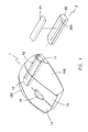
- FIG. 1 is a schematic, partly exploded view of an electronic device according to an embodiment of the present invention.
- FIG. 2 is a schematic, isometric view of an electronic device according to an embodiment of the present invention.
- FIG. 3 is a schematic view of an electronic device according to an embodiment of the present invention, when a power supply unit is replaced.
- FIG. 4 is a schematic view of an electronic device according to an embodiment of the present invention, showing replacing a power supply unit without interrupting power supply.
- FIG. 5 is a schematic view of a positioning structure of an electronic device according to an embodiment of the present invention.
- FIGS. 1-5 show an electronic device according to an embodiment of the present invention.
- the electronic device is a mouse for exemplary purposes, but may be other portable electronic devices that need to replace a battery, such as a mobile phone, a personal digital assistant and an MP3 player.
- the electronic device includes a housing 1, a power supply unit 2 and a circuit (not shown).
- the circuit can be a mouse circuit.
- the housing 1 defines a receiving cavity 10 therein, and has a first surface 110 and a second surface 120 on opposite sides thereof.
- An inlet 11 is defined in the first side surface 110
- an outlet 12 is defined in the second surface 120.
- the receiving cavity 10 is straightly connected with the inlet 11 and the outlet 12.
- the housing 1 includes a left button 13, a right button 14 and a wheel 15 in the front of the housing 1.
- the left button 13, the right button 14 and the wheel 15 are used to control the circuit.
- the receiving cavity 10 is preferably located adjacent to the back of the housing 1, so that the receiving cavity 10 can stand aside from some mechanisms that are congregated in the front of the housing 1, such as the left button 13, the right button 14, the wheel 15 and the circuit.
- the power supply unit 2 can includes a battery base 20.
- the battery base 20 defines a battery groove 201 for receiving at least a battery 21.
- the power supply unit 2 can be just a battery.
- the power supply unit 2 has been inserted in the receiving cavity 10 of the housing 10.
- the power supply unit 2 is connected with the inlet 11 and the outlet 12 and a shape of the power supply unit 2 corresponds to that of the receiving cavity 10, the power supply unit 2 can easily enter the receiving cavity 10 via the inlet 11 and exit from the receiving cavity 10 via the outlet 12.
- another power supply unit 3 (regarding as a new battery) that is same to the power supply unit 2 is used to replace the power supply unit 2 (regarding as an old battery), and the purpose of replacing power supply unit (regarding as the battery) in the electronic device is achieved.
- the power supply unit 2 is pushed out of the receiving cavity 10 by the another power supply unit 3, with the another power supply unit 3 entering the cavity 10. In other words, discharging the power supply unit 2 and mounting the power supply unit 3 are carried out at the same time.
- the electronic device of the embodiment of the present invention when compared with the traditional process of replacing battery (which includes two steps/actions, firstly, the old battery is taken out firstly, and then the new battery is mounted), the electronic device of the embodiment of the present invention only has a single action/ step for discharging the power supply unit 2 and mounting the another power supply unit 3, and thus the process of the replacing battery of the electronic device of the embodiment of the present invention can be conveniently and easily.
- the housing 1 has a first conductive structure formed in the receiving cavity 10.
- the first conductive structure is connected with the circuit, and includes an anode surface 100 and a cathode surface 101.
- the anode surface 100 and the cathode surface 101 respectively extend from the inlet 11 to the outlet 12.
- the power supply unit 2 has a second conductive structure on an outer surface of the power supply unit 2.
- the second conductive structure includes an anode surface 200 and a cathode surface 201.
- the anode surface 200 and the cathode surface 201 respectively extend from one end to another end of the long edge of the power supply unit 2
- an anode surface 300 and a cathode surface 301 of the another power supply unit 3 are respectively connected with the anode surface 100 and the cathode surface 101 of the first conductive structure in the receiving cavity 10.
- the anode surface 200 and the cathode surface 201 of the power supply unit 2 are respectively always connected with the anode surface 100 and the cathode surface 101 of the first conductive structure in the receiving cavity 10.
- the first conductive structure and the second conductive structure always keep connection with the circuit, and the electric power for the electronic device can be supplied by the power supply unit 2 and/or the another power supply unit 3.
- a power-up state of the electronic device can be kept. That is when the power supply unit 2 is replaced by a user, the electronic device can always work, and thus the electronic device can be used without restarting.
- the electronic device of the embodiment of the present invention that do not require to interrupt the power supply can be conveniently.
- the anode surface and the cathode surface can be coplanar, or the anode surface and the cathode surface can be respectively made of a plurality of small surfaces that are discontinuous. It should point out that, whatever the configuration of the first conductive structure and the second conductive structure is, it should satisfy that the power supply unit 2 of the electronic device is replaced without interrupting the power supply.
- the electronic device further includes a positioning structure 4 disposed in the housing 1.
- the positioning structure 4 can make the power supply unit 2 fixed in the receiving cavity 10.
- the positioning structure 4 includes two shallow arcuate slots 40 disposed at an outer surface of the battery base 20 and two elastic positioning members 41 disposed in the housing 1.
- the elastic positioning member 41 includes a bead 410 and a compression spring 411.
- the compression spring 411 can keep making the bead 410 resist with the battery base 20, till the battery base 20 arrives at a predetermined location and the compression spring 411 pushes a portion of the bead 410 into the shallow arcuate slot 40 so that the battery base 20 can be fixed in the receiving cavity 10.
Landscapes
- Engineering & Computer Science (AREA)
- Electrochemistry (AREA)
- Biophysics (AREA)
- Computer Hardware Design (AREA)
- Chemical & Material Sciences (AREA)
- Chemical Kinetics & Catalysis (AREA)
- Life Sciences & Earth Sciences (AREA)
- General Chemical & Material Sciences (AREA)
- General Engineering & Computer Science (AREA)
- Theoretical Computer Science (AREA)
- Human Computer Interaction (AREA)
- Physics & Mathematics (AREA)
- General Physics & Mathematics (AREA)
- Battery Mounting, Suspending (AREA)
Abstract
Description
- The present invention relates to an electronic device, and more particularly to a wireless mouse.
- Typically, a wireless mouse only has an opening for placing or removing a battery. Therefore, if the old battery is replaced, power supply would be interrupted. As such, a new battery can not be mounted until the old battery is taken out firstly.
- Taiwan Patent Publication No.
I296770 - The present invention provides an electronic device, which includes a housing and a power supply unit. The housing has a first side surface and a second side surface on opposite sides thereof and a receiving cavity defined therein, an inlet being defined in the first side surface and an outlet beingdefined in the second side surface. The receiving cavity is connected with the inlet and the outlet. The power supply unit is located in the receiving cavity, and a shape of the power supply unit corresponds to that of the receiving cavity. In the above electronic device, when a new power supply unit is inserted in the receiving cavity via the inlet, the old power supply unit can be pushed out of the receiving cavity via the outlet by the new power supply unit at the same time. Therefore, the power supply unit can be replaced by a single action/step.
- In an embodiment of the present invention, the electronic device further includes a circuit located in the housing. The housing has a first conductive structure formed in the receiving cavity. The power supply unit has a second conductive structure. The first conductive structure corresponds to the second conductive structure. When the power supply unit is pushed out of the receiving cavity by another power supply unit, the first conductive structure and the second conductive structure always keep connection with the circuit. As such, the power supply unit of the electronic device can be replaced without interrupting the power supply.
- In an embodiment of the present invention, the electronic device further includes a positioning structure disposed in the housing. The positioning structure can make the power supply unit fixed in the receiving cavity.
- These and other features and advantages of the various embodiments disclosed herein will be better understood with respect to the following description and drawings, in which like numbers refer to like parts throughout, and in which:
-
FIG. 1 is a schematic, partly exploded view of an electronic device according to an embodiment of the present invention. -
FIG. 2 is a schematic, isometric view of an electronic device according to an embodiment of the present invention. -
FIG. 3 is a schematic view of an electronic device according to an embodiment of the present invention, when a power supply unit is replaced. -
FIG. 4 is a schematic view of an electronic device according to an embodiment of the present invention, showing replacing a power supply unit without interrupting power supply. -
FIG. 5 is a schematic view of a positioning structure of an electronic device according to an embodiment of the present invention. -
FIGS. 1-5 show an electronic device according to an embodiment of the present invention. The electronic device is a mouse for exemplary purposes, but may be other portable electronic devices that need to replace a battery, such as a mobile phone, a personal digital assistant and an MP3 player. - Referring to
FIG. 1 , the electronic device includes ahousing 1, apower supply unit 2 and a circuit (not shown). The circuit can be a mouse circuit. - The
housing 1 defines areceiving cavity 10 therein, and has afirst surface 110 and asecond surface 120 on opposite sides thereof. Aninlet 11 is defined in thefirst side surface 110, and anoutlet 12 is defined in thesecond surface 120. Thereceiving cavity 10 is straightly connected with theinlet 11 and theoutlet 12. In addition, thehousing 1 includes aleft button 13, aright button 14 and awheel 15 in the front of thehousing 1. Theleft button 13, theright button 14 and thewheel 15 are used to control the circuit. Thereceiving cavity 10 is preferably located adjacent to the back of thehousing 1, so that thereceiving cavity 10 can stand aside from some mechanisms that are congregated in the front of thehousing 1, such as theleft button 13, theright button 14, thewheel 15 and the circuit. - In a described embodiment, the
power supply unit 2 can includes abattery base 20. Thebattery base 20 defines abattery groove 201 for receiving at least abattery 21. In an alternative embodiment, thepower supply unit 2 can be just a battery. - As shown in
FIG. 2 , thepower supply unit 2 has been inserted in thereceiving cavity 10 of thehousing 10. - Because the
power supply unit 2 is connected with theinlet 11 and theoutlet 12 and a shape of thepower supply unit 2 corresponds to that of thereceiving cavity 10, thepower supply unit 2 can easily enter thereceiving cavity 10 via theinlet 11 and exit from thereceiving cavity 10 via theoutlet 12. - As shown in
FIG. 3 , another power supply unit 3 (regarding as a new battery) that is same to thepower supply unit 2 is used to replace the power supply unit 2 (regarding as an old battery), and the purpose of replacing power supply unit (regarding as the battery) in the electronic device is achieved. In a process of replacing thepower supply unit 2, thepower supply unit 2 is pushed out of thereceiving cavity 10 by the anotherpower supply unit 3, with the anotherpower supply unit 3 entering thecavity 10. In other words, discharging thepower supply unit 2 and mounting thepower supply unit 3 are carried out at the same time. Therefore, when compared with the traditional process of replacing battery (which includes two steps/actions, firstly, the old battery is taken out firstly, and then the new battery is mounted), the electronic device of the embodiment of the present invention only has a single action/ step for discharging thepower supply unit 2 and mounting the anotherpower supply unit 3, and thus the process of the replacing battery of the electronic device of the embodiment of the present invention can be conveniently and easily. - As shown in
FIG. 4 , thehousing 1 has a first conductive structure formed in thereceiving cavity 10. The first conductive structure is connected with the circuit, and includes ananode surface 100 and acathode surface 101. Theanode surface 100 and thecathode surface 101 respectively extend from theinlet 11 to theoutlet 12. Thepower supply unit 2 has a second conductive structure on an outer surface of thepower supply unit 2. The second conductive structure includes ananode surface 200 and acathode surface 201. Theanode surface 200 and thecathode surface 201 respectively extend from one end to another end of the long edge of thepower supply unit 2 - After a portion of another
power supply unit 3 enters thereceiving cavity 10, ananode surface 300 and acathode surface 301 of the anotherpower supply unit 3 are respectively connected with theanode surface 100 and thecathode surface 101 of the first conductive structure in thereceiving cavity 10. Before thepower supply unit 2 is pushed out of the receivingcavity 10, theanode surface 200 and thecathode surface 201 of thepower supply unit 2 are respectively always connected with theanode surface 100 and thecathode surface 101 of the first conductive structure in thereceiving cavity 10. In other words, when thepower supply unit 2 is pushed out of thereceiving cavity 10 by the anotherpower supply unit 3, the first conductive structure and the second conductive structure always keep connection with the circuit, and the electric power for the electronic device can be supplied by thepower supply unit 2 and/or the anotherpower supply unit 3. As such, when thepower supply unit 2 is replaced, a power-up state of the electronic device can be kept. That is when thepower supply unit 2 is replaced by a user, the electronic device can always work, and thus the electronic device can be used without restarting. In comparison to the traditional process of replacing battery in which the power supply need to be interrupted, the electronic device of the embodiment of the present invention that do not require to interrupt the power supply can be conveniently. - Configuration of the first conductive structure and the second conductive structure of
FIG. 4 is an example, and the present invention is not limited herein. For example, the anode surface and the cathode surface can be coplanar, or the anode surface and the cathode surface can be respectively made of a plurality of small surfaces that are discontinuous. It should point out that, whatever the configuration of the first conductive structure and the second conductive structure is, it should satisfy that thepower supply unit 2 of the electronic device is replaced without interrupting the power supply. - As shown in
FIG. 5 , the electronic device further includes apositioning structure 4 disposed in thehousing 1. Thepositioning structure 4 can make thepower supply unit 2 fixed in the receivingcavity 10. In a described embodiment, thepositioning structure 4 includes two shallowarcuate slots 40 disposed at an outer surface of thebattery base 20 and twoelastic positioning members 41 disposed in thehousing 1. Theelastic positioning member 41 includes abead 410 and acompression spring 411. When thebattery base 20 is pushed into the receivingcavity 10, thecompression spring 411 can keep making thebead 410 resist with thebattery base 20, till thebattery base 20 arrives at a predetermined location and thecompression spring 411 pushes a portion of thebead 410 into the shallowarcuate slot 40 so that thebattery base 20 can be fixed in the receivingcavity 10. - The above description is given by way of example, and not limitation. Given the above disclosure, one skilled in the art could devise variations that are within the scope and spirit of the invention disclosed herein, including configurations ways of the recessed portions and materials and/or designs of the attaching structures. Further, the various features of the embodiments disclosed herein can be used alone, or in varying combinations with each other and are not intended to be limited to the specific combination described herein. Thus, the scope of the claims is not to be limited by the illustrated embodiments.
Claims (7)
- An electronic device, comprising:a housing having a first side surface and a second side surface on opposite sides thereof and a receiving cavity defined therein, an inlet being defined in the first side surface, an outlet being defined in the second side surface, and the receiving cavity being connected with the inlet and the outlet; anda power supply unit located in the receiving cavity, a shape of the power supply unit corresponding to that of the receiving cavity.
- The electronic device as claimed in claim 1, further comprising a circuit located in the housing, the housing having a first conductive structure formed in the receiving cavity, the power supply unit having a second conductive structure, the first conductive structure corresponding to the second conductive structure, when the power supply unit is pushed out of the receiving cavity by another power supply unit, the first conductive structure and the second conductive structure always keep connection with the circuit.
- The electronic device as claimed in claim 2, further comprising a positioning structure disposed in the housing, the positioning structure making the power supply unit fixed in the receiving cavity.
- The electronic device as claimed in claim 3, wherein the power supply unit comprises a battery base defining a groove for receiving at least a battery, the second conductive structure disposed at an outer surface of the battery base.
- The electronic device as claimed in claim 3, wherein the positioning structure comprises at least a shallow arcuate slot disposed at an outer surface of the power supply unit and an elastic positioning member disposed in the housing, the elastic positioning member including a bead and a compression spring, when the power supply unit is pushed into the receiving cavity, the compression spring keeps making the bead resist with the power supply unit, till the power supply unit arrives at a predetermined location and the compression spring pushes a portion of the bead into the at least a shallow arcuate slot.
- The electronic device as claimed in claim 2, wherein the housing comprises a left button and a right button, the circuit is a mouse circuit, and the receiving cavity is adjacent to a back of the housing.
- The electronic device as claimed in claim 1, wherein the receiving cavity is straightly connected with the inlet and the outlet.
Priority Applications (1)
| Application Number | Priority Date | Filing Date | Title |
|---|---|---|---|
| EP09006867A EP2254024A1 (en) | 2009-05-21 | 2009-05-21 | Device for changing batteries |
Applications Claiming Priority (1)
| Application Number | Priority Date | Filing Date | Title |
|---|---|---|---|
| EP09006867A EP2254024A1 (en) | 2009-05-21 | 2009-05-21 | Device for changing batteries |
Publications (1)
| Publication Number | Publication Date |
|---|---|
| EP2254024A1 true EP2254024A1 (en) | 2010-11-24 |
Family
ID=41059494
Family Applications (1)
| Application Number | Title | Priority Date | Filing Date |
|---|---|---|---|
| EP09006867A Ceased EP2254024A1 (en) | 2009-05-21 | 2009-05-21 | Device for changing batteries |
Country Status (1)
| Country | Link |
|---|---|
| EP (1) | EP2254024A1 (en) |
Citations (9)
| Publication number | Priority date | Publication date | Assignee | Title |
|---|---|---|---|---|
| JPS61135050A (en) * | 1984-12-04 | 1986-06-23 | Toshiba Corp | Load dispatching device |
| US5043888A (en) * | 1990-04-12 | 1991-08-27 | Uriarte Jorge E | Fertility indicator |
| JPH04286860A (en) * | 1991-03-18 | 1992-10-12 | Fujitsu Ltd | Battery replacing method |
| JPH09285036A (en) * | 1996-04-15 | 1997-10-31 | Matsushita Electric Ind Co Ltd | Electronic equipment |
| US5863218A (en) * | 1996-01-24 | 1999-01-26 | Motorola, Inc. | Battery terminal coupling assembly |
| JP2000092747A (en) * | 1998-09-07 | 2000-03-31 | Matsushita Electric Ind Co Ltd | Information processing device that can replace the battery pack during operation |
| US20020005834A1 (en) * | 2000-04-07 | 2002-01-17 | Seung-Hwan Oh | Computer mouse having data recording and decodeing function |
| US20030179177A1 (en) * | 2002-03-21 | 2003-09-25 | Paten Wireless Technology Inc. | Wireless input device |
| TWI296770B (en) | 2006-01-16 | 2008-05-11 | Darfon Electronics Corp | Wireless input devices |
-
2009
- 2009-05-21 EP EP09006867A patent/EP2254024A1/en not_active Ceased
Patent Citations (9)
| Publication number | Priority date | Publication date | Assignee | Title |
|---|---|---|---|---|
| JPS61135050A (en) * | 1984-12-04 | 1986-06-23 | Toshiba Corp | Load dispatching device |
| US5043888A (en) * | 1990-04-12 | 1991-08-27 | Uriarte Jorge E | Fertility indicator |
| JPH04286860A (en) * | 1991-03-18 | 1992-10-12 | Fujitsu Ltd | Battery replacing method |
| US5863218A (en) * | 1996-01-24 | 1999-01-26 | Motorola, Inc. | Battery terminal coupling assembly |
| JPH09285036A (en) * | 1996-04-15 | 1997-10-31 | Matsushita Electric Ind Co Ltd | Electronic equipment |
| JP2000092747A (en) * | 1998-09-07 | 2000-03-31 | Matsushita Electric Ind Co Ltd | Information processing device that can replace the battery pack during operation |
| US20020005834A1 (en) * | 2000-04-07 | 2002-01-17 | Seung-Hwan Oh | Computer mouse having data recording and decodeing function |
| US20030179177A1 (en) * | 2002-03-21 | 2003-09-25 | Paten Wireless Technology Inc. | Wireless input device |
| TWI296770B (en) | 2006-01-16 | 2008-05-11 | Darfon Electronics Corp | Wireless input devices |
Non-Patent Citations (1)
| Title |
|---|
| ANONYMOUS: "Ball detent - Wikipedia, the free encyclopedia", 10 November 2008 (2008-11-10), XP055168053, Retrieved from the Internet <URL:http://en.wikipedia.org/w/index.php?title=Ball_detent&oldid=250984054> [retrieved on 20150206] * |
Similar Documents
| Publication | Publication Date | Title |
|---|---|---|
| US8088507B2 (en) | Portable electronic device having secured battery | |
| US20040264720A1 (en) | Wireless earphone having replaceable battery module | |
| US9465420B2 (en) | Electronic devices having integrated reset systems and methods thereof | |
| US20020197965A1 (en) | Protective mask of mobile phone | |
| US9103484B2 (en) | Connection device | |
| CN201639740U (en) | Bluetooth headset for portable terminal | |
| CN105489427B (en) | Press-key structure and mobile terminal device | |
| US20090114458A1 (en) | Portable electronic device and method for operating the same | |
| CN103248732A (en) | Mobile terminal and card accommodation device | |
| US7837487B2 (en) | Card socket assembly | |
| US8199467B2 (en) | Battery ejector and electronic device using the same | |
| US20130162541A1 (en) | Control key assembly for portable electronic device | |
| KR20130090667A (en) | Portable charger for cell phone | |
| US20100178542A1 (en) | Electronic device | |
| US20100328213A1 (en) | Electronic Device Capable of Replacing Battery Easily | |
| US7753702B2 (en) | Card socket assembly | |
| EP2254024A1 (en) | Device for changing batteries | |
| CN203135970U (en) | Rapid power-down device for cell phone and cell phone by using device thereof | |
| CN105071823A (en) | Mobile terminal including power on-off mechanism | |
| CN203340126U (en) | mobile terminal | |
| WO2013174059A1 (en) | Apparatus and method for identifying batteries of different thicknesses, and electronic device | |
| KR101967158B1 (en) | Case for Mobile Device for Easy Attach and Detach Accessories | |
| CN213519683U (en) | Side button structure and electronic equipment | |
| US8611098B2 (en) | Releasing apparatus for SIM card | |
| CN212783224U (en) | Switch assembly and electronic equipment |
Legal Events
| Date | Code | Title | Description |
|---|---|---|---|
| PUAI | Public reference made under article 153(3) epc to a published international application that has entered the european phase |
Free format text: ORIGINAL CODE: 0009012 |
|
| AK | Designated contracting states |
Kind code of ref document: A1 Designated state(s): AT BE BG CH CY CZ DE DK EE ES FI FR GB GR HR HU IE IS IT LI LT LU LV MC MK MT NL NO PL PT RO SE SI SK TR |
|
| AX | Request for extension of the european patent |
Extension state: AL BA RS |
|
| 17P | Request for examination filed |
Effective date: 20110519 |
|
| 17Q | First examination report despatched |
Effective date: 20110610 |
|
| RAP1 | Party data changed (applicant data changed or rights of an application transferred) |
Owner name: GIGA-BYTE TECHNOLOGY CO., LTD. |
|
| STAA | Information on the status of an ep patent application or granted ep patent |
Free format text: STATUS: THE APPLICATION HAS BEEN REFUSED |
|
| 18R | Application refused |
Effective date: 20161121 |