EP2253939A2 - Multi-rotation angle detection device - Google Patents
Multi-rotation angle detection device Download PDFInfo
- Publication number
- EP2253939A2 EP2253939A2 EP10161247A EP10161247A EP2253939A2 EP 2253939 A2 EP2253939 A2 EP 2253939A2 EP 10161247 A EP10161247 A EP 10161247A EP 10161247 A EP10161247 A EP 10161247A EP 2253939 A2 EP2253939 A2 EP 2253939A2
- Authority
- EP
- European Patent Office
- Prior art keywords
- gear
- driven gear
- rotor
- detection device
- rotation angle
- Prior art date
- Legal status (The legal status is an assumption and is not a legal conclusion. Google has not performed a legal analysis and makes no representation as to the accuracy of the status listed.)
- Withdrawn
Links
- 238000001514 detection method Methods 0.000 title claims description 64
- 239000000758 substrate Substances 0.000 claims description 14
- 238000000034 method Methods 0.000 description 5
- 238000004519 manufacturing process Methods 0.000 description 3
- 239000000463 material Substances 0.000 description 2
- 229930182556 Polyacetal Natural products 0.000 description 1
- 238000005299 abrasion Methods 0.000 description 1
- 238000005259 measurement Methods 0.000 description 1
- 230000007935 neutral effect Effects 0.000 description 1
- 229920006324 polyoxymethylene Polymers 0.000 description 1
- 229920003002 synthetic resin Polymers 0.000 description 1
- 239000000057 synthetic resin Substances 0.000 description 1
Images


Classifications
-
- G—PHYSICS
- G01—MEASURING; TESTING
- G01D—MEASURING NOT SPECIALLY ADAPTED FOR A SPECIFIC VARIABLE; ARRANGEMENTS FOR MEASURING TWO OR MORE VARIABLES NOT COVERED IN A SINGLE OTHER SUBCLASS; TARIFF METERING APPARATUS; MEASURING OR TESTING NOT OTHERWISE PROVIDED FOR
- G01D5/00—Mechanical means for transferring the output of a sensing member; Means for converting the output of a sensing member to another variable where the form or nature of the sensing member does not constrain the means for converting; Transducers not specially adapted for a specific variable
- G01D5/12—Mechanical means for transferring the output of a sensing member; Means for converting the output of a sensing member to another variable where the form or nature of the sensing member does not constrain the means for converting; Transducers not specially adapted for a specific variable using electric or magnetic means
- G01D5/14—Mechanical means for transferring the output of a sensing member; Means for converting the output of a sensing member to another variable where the form or nature of the sensing member does not constrain the means for converting; Transducers not specially adapted for a specific variable using electric or magnetic means influencing the magnitude of a current or voltage
- G01D5/142—Mechanical means for transferring the output of a sensing member; Means for converting the output of a sensing member to another variable where the form or nature of the sensing member does not constrain the means for converting; Transducers not specially adapted for a specific variable using electric or magnetic means influencing the magnitude of a current or voltage using Hall-effect devices
- G01D5/145—Mechanical means for transferring the output of a sensing member; Means for converting the output of a sensing member to another variable where the form or nature of the sensing member does not constrain the means for converting; Transducers not specially adapted for a specific variable using electric or magnetic means influencing the magnitude of a current or voltage using Hall-effect devices influenced by the relative movement between the Hall device and magnetic fields
-
- G—PHYSICS
- G01—MEASURING; TESTING
- G01D—MEASURING NOT SPECIALLY ADAPTED FOR A SPECIFIC VARIABLE; ARRANGEMENTS FOR MEASURING TWO OR MORE VARIABLES NOT COVERED IN A SINGLE OTHER SUBCLASS; TARIFF METERING APPARATUS; MEASURING OR TESTING NOT OTHERWISE PROVIDED FOR
- G01D2205/00—Indexing scheme relating to details of means for transferring or converting the output of a sensing member
- G01D2205/20—Detecting rotary movement
- G01D2205/26—Details of encoders or position sensors specially adapted to detect rotation beyond a full turn of 360°, e.g. multi-rotation
Definitions
- the present invention relates to a multi-rotation angle detection device for detecting a rotating angle of a multi-rotation body which rotates in a limited angular range in excess of 360°, for example, a steering shaft for an automobile.
- the multi-rotation angle detection device of the aforementioned type includes a gear of a rotating body which rotates in association with a steering, two gears each having a different number of teeth in engagement with the gear of the rotating body, magnets respectively attached to the two gears, and angular sensors corresponding to those magnets. Based on measurement results of those angular sensors, a predetermined arithmetic expression is calculated to obtain the angle of the rotating body as disclosed in Japanese Unexamined Patent Application Publication (Translation of PCT Application) No. 11-500828 , for example.
- the generally employed rotating angle detection device is provided with the gear of the rotating body and two gears each having different number of teeth in engagement with the gear of the rotating body in a single plane, which may cause the problem of enlarged external dimension of the multi-rotation angle detection device.
- the present invention provides a multi-rotation angle detection device with a small external dimension.
- the multi-rotation angle detection device includes a rotor having a first gear and a second gear each with a different number of teeth, which are concentrically provided for a flanged gear forming section, a first driven gear which has a first rotating axis orthogonalized to a plane which includes a rotating axis of the rotor, and is engaged with the first gear, a second driven gear which has a second rotating axis orthogonalized to the plane, and is engaged with the second gear, a first magnet attached to the first driven gear, a second magnet attached to the second driven gear, a circuit substrate disposed at a position opposite a magnet mount surface of the first driven gear and a magnet mount surface of the second driven gear, a first magnetic detection element disposed at a position opposite the first magnet above the circuit substrate, a second magnetic detection element disposed at a position opposite the second magnet above the circuit substrate, and a housing which stores the aforementioned members.
- the aforementioned structure allows the first and the second driven gears to be arranged by orthogonalizing the first and the second rotating axes thereof with respect to the plane which includes the rotating axis of the rotor such that each magnet mount surface of the first and the second driven gears may be disposed parallel to the plane which includes the rotating axis of the rotor.
- This makes it possible to reduce the plane size of the multi-rotation angle detection device.
- Both the first and the second magnetic detection elements may be mounted on a single circuit substrate to minimize the number of substrates, thus reducing the manufacturing cost of the multi-rotation angle detection device.
- the detection signal from the first magnetic detection element corresponding to rotation of the first driven gear is compared with the detection signal from the second magnetic detection element corresponding to rotation of the second driven gear for detecting the failure.
- the resultant multi-rotation angle detection device exhibits improved reliability and fail-safe property.
- the device according to the present invention is structured to have the first and the second gears formed at the lower surface side of the gear forming section.
- the above structure allows the side configuration of the housing which stores the first and the second driven gears and the rotor to be formed into substantially L-like shape, thus further reducing the plane size of the multi-rotation angle detection device.
- the multi-rotation angle detection device is structured to arrange the first and the second driven gears by orthogonalizing the first and the second rotating axes thereof with respect to the plane which includes the rotating axis of the rotor having the first and the second gears each with different number of teeth concentrically provided for the flanged gear forming section.
- the magnet mount surfaces of the first and the second driven gears may be disposed parallel to the plane which includes the rotating axis of the rotor, thus reducing the plane size of the multi-rotation angle detection device.
- a mechanical structure of the multi-rotation angle detection device according to the embodiment will be described by taking examples.
- a multi-rotation angle detection device has a first driven gear 13 and a second driven gear 14 disposed at the lower surface side of a flanged gear forming section 1a integrally formed with a rotor 1.
- the multi-rotation angle detection device includes a cylindrical rotor 1 attached to a rotating body such as a steering shaft so as to rotate together with the rotating body, and a housing (stator) 2 which is fixed to a not shown stator portion around the rotating body for rotatably holding the rotor 1.
- the housing 2 is formed by combining a case 3, a top cover 4a and a side cover 4b to form an L-like side view as shown in Fig. 2 .
- Each of the rotor 1 and the housing 2 is formed of a synthetic resin material. Especially polyacetal is used for forming the rotor 1 for the purpose of providing smooth rotating operation and excellent sliding abrasion property.
- the flanged gear forming section 1a is integrally formed on the outer surface of the rotor 1.
- a first gear 11 and a second gear 12 each having different number of teeth are formed at the lower surface side of the gear forming section 1a concentrically with respect to the rotating axis of the rotating body, that is, the rotating axis Y-Y of the rotor 1.
- the first gear 11 which is formed at the outer circumference of the second gear 12, having the number of teeth larger than that of the second gear 12 is engaged with the first driven gear 13.
- the second gear 12 which is formed at the inner circumference of the first gear 11, having the number of teeth smaller than that of the first gear 11 is engaged with the second driven gear 14. Referring to Figs. 1 and 2 , the first driven gear 13 and the second driven gear 14 are rotatably held in the case 3.
- the plane which includes the rotating axis Y-Y of the rotor 1 is arranged to be orthogonal to a rotating axis X1-X1 of the first driven gear 13.
- the plane which includes the rotating axis Y-Y of the rotor 1 is arranged to be orthogonal to a rotating axis X2-X2 of the second driven gear 14.
- the rotating axis X1-X1 is positioned parallel to the rotating axis X2-X2.
- the gear for orthogonally crossed axis or orthogonally stagger axis may be employed for the first gear 11, the first driven gear 13 engaged therewith, the second gear 12, and the second driven gear 14 engaged therewith.
- a straight bevel gear or a spiral bevel type face gear may be employed.
- a face gear may be employed.
- the appropriate gear is selected in accordance with the external configuration of the desired device.
- the aforementioned structure allows the first driven gear 13 and the second driven gear 14 to be arranged such that a magnet mount surface 13a of the first driven gear 13 and a magnet mount surface 14a of the second driven gear 14 are aligned in the same plane.
- This makes it possible to form the side configuration of the housing 2 for storing the first and the second driven gears 13, 14 and the rotor 1 into substantially L-like shape, thus reducing the plane size of the multi-rotation angle detection device.
- a first magnet 18 is attached to the magnet mount surface 13a of the first driven gear 13, and a second magnet 19 is attached to the magnet mount surface 14a of the second driven gear 14, respectively.
- Each of those first and the second magnets 18, 19 is formed into a ring shape so as to be buried in the magnet mount surface 13a of the first driven gear 13 and the magnet mount surface 14a of the second driven gear 14, respectively.
- a circuit substrate 22 is provided at a position opposite the magnet mount surface 13a of the first driven gear 13 and the magnet mount surface 14a of the second driven gear 14 in the housing 2.
- a first magnetic detection element 20 for detecting change in the magnetic field in association with the rotation of the first driven gear 13 is provided on the circuit substrate 22 at the position opposite the first magnet 18.
- a second magnetic detection element 21 for detecting change in the magnetic field in association with the rotation of the second driven gear 14 is provided at the position opposite the second magnet 19.
- a GMR (Giant Magneto-Resistive) sensor which is unlikely to be influenced by the change in the magnetic field intensity and exhibits high temperature stability may be employed for those magnetic detection elements 20 and 21.
- the circuit substrate 22 is also provided with a microprocessor 23 for calculating a rotating angle of the rotor 1 based on the detection signals from the first and the second magnetic detection elements 20, 21.
- the maximum rotating number of the rotor 1 is set to N (N:integer)
- the gear ratio between the first gear 11 and the first driven gear 13 is set to n (n: integer)
- the number of teeth of the first gear 11 is obtained as being m times the value of N x n (m:integer).
- the number of teeth of the second gear 12 is obtained as being m times the value of N x n-1 (m:integer).
- Combination of the numbers of teeth of the first gear 11 and the second gear 12 is not limited to the aforementioned example, and the values shown in Fig. 4 may be employed.
- the number of teeth of the first driven gear 13 is obtained by multiplying N by the difference of the number of teeth between the first gear 11 and the second gear 12.
- N is set to 4, and the difference of the number of teeth is 8 (64-56). Therefore, the number of teeth of the first driven gear 13 becomes 32 (4 x 8).
- the number of teeth of the second driven gear 14 is obtained likewise the case of the first driven gear 13. In the example, the number of teeth of the second driven gear 14 becomes 32.
- the multi-rotation angle detection device of the embodiment has the first driven gear 13 and the second driven gear 14 disposed below the gear forming section 1a. Unlike the case for arranging the first and the second driven gears 13 and 14 on an outer circumference of the gear forming section 1a, the present structure may reduce the plane size L of the housing 2. As the magnet mount surface 13a of the first driven gear 13 and the magnet mount surface 14a of the second driven gear 14 are arranged in the same plane, both the first and the second magnetic detection elements 20, 21 may be mounted on the single circuit substrate 22, thus reducing the manufacturing cost of the multi-rotation angle detection device.
- the multi-rotation angle detection device includes the first driven gear 13 at the lower surface side of the flanged gear forming section 1a integrally formed with the rotor 1, and the second driven gear 14 at the upper surface side of the gear forming section 1a as shown in Figs. 5 to 7 .
- the first gear 11 is formed at the lower surface side of the gear forming section 1a
- the second gear 12 is formed at the upper surface side.
- the first driven gear 13 and the second driven gear 14 are disposed in the same radius of the gear forming section 1a, and the magnet mount surface 13a of the first driven gear 13 and the magnet mount surface 14a of the second driven gear 14 are arranged in the same plane.
- the housing 2 has substantially T-like side configuration as shown in Fig. 6 .
- Other features of the modified example are the same as those of the multi-rotation angle detection device according to the example.
- the corresponding elements are designated with the same codes, and explanation thereof will be omitted.
- the multi-rotation angle detection device includes the first driven gear 13 and the second driven gear 14 at the upper surface side of the flanged gear forming section 1a integrally formed with the rotor 1.
- the first gear 11 and the second gear 12 are formed at the upper surface side of the gear forming section 1a.
- the housing 2 has substantially L-like side configuration at the inverted side of the multi-rotation angle detection device of the example as described above.
- Other features are the same as those of the multi-rotation angle detection device of the example.
- the corresponding elements are designated with the same codes, and explanation thereof will be omitted.
- the microprocessor 23 calculates a first angle signal A1 having the output value linearly changed from 0% to 100% while the first driven gear 13 is rotating at the angle from 0° to 360°, and a second angle signal A2 having the output value linearly changed from 0% to 100% while the second driven gear 14 is rotating at the angle from 0° to 360° based on output signals from the first magnetic detection element 20 and the second magnetic detection element 21.
- each output value irregularly returns to 0% to linearly increase the value again in association with each rotation of the respective driven gears 13 and 14.
- the microprocessor 23 executes the arithmetic process for obtaining the absolute rotating angle of the rotor 1 based on the first angle signal A1 and the second angle signal A2.
- the arithmetic process includes first step (S1) for obtaining a difference between detected values of the first angle signal A1 and the second angle signal A2, second step (S2) for correcting the difference, and third step (S3) for calculating the absolute angle of the rotor 1.
- first step (S1) as shown in Fig. 10B , the output value of the second angle signal A2 is subtracted from the output value of the first angle signal A1 to obtain a difference signal A3.
- the difference signal A3 takes a different value depending on the absolute angle of the rotor 1.
- second step (S2) when the difference signal A3 indicates the negative value, 100 is added to the difference value to calculate a correction signal A4 as shown in Fig. 10C .
- the correction signal A4 corresponds to the absolute angle to be detected one-on-one over the entire range. As a result, the value linearly changes from 0% to 100%.
- third step (S3) the absolute angle of the rotor 1 which makes more than one rotation, that is, the rotating body is detected based on the correction signal A4.
- the rotor 1 When the driver operates a steering wheel of the automobile, the rotor 1 is rotated together with the steering wheel. Then the first driven gear 13 rotates via the first gear 11 and the second driven gear 14 rotates via the second gear 12.
- the first driven gear 13 will make one rotation for each rotation of the rotor 1 at 180°.
- the first angle signal A1 during the aforementioned period is expressed as a triangular wave which changes from 0% to 100%.
- the first driven gear 13 makes eight rotations while the rotor 1 is making four rotations to change the absolute angle from 0° to 1440°. Accordingly, the resultant triangular wave forms eight cycles as shown in Fig. 10A .
- the gear ratio between the second gear 12 and the second driven gear 14 is set to the value "1.75"
- the second driven gear 14 will make seven rotations while the rotor 1 is making 4 rotations. Accordingly, the second angle signal A2 expressed as the triangular wave forms seven cycles as a whole as shown in Fig. 10A .
- first step (S1) where the first angle signal A1 and the second angle signal A2 are processed, the difference signal A3 as the output difference between the first angle signal A1 and the second angle signal A1 is calculated as shown in Fig. 10B .
- the calculated value is corrected in second step (S2) to calculate the correction signal A4 as shown in Fig. 10C .
- third step (S3) the absolute angle of the rotor 1 which makes more than one rotation, that is, the rotating body is detected based on the correction signal A4.
- the multi-rotation angle detection device is structured to arrange the first and the second driven gears 13, 14 while having the first and the second rotating axes X1-X1 and X2-X2 thereof orthogonalized with respect to the plane which includes the rotating axis Y-Y of the rotor 1.
- the magnet mount surfaces 13a and 14a of the first and the second driven gears 13 and 14 may be arranged parallel to the plane which includes the rotating axis Y-Y of the rotor 1 so as to reduce the plane size of the multi-rotation angle detection device.
- the first driven gear 13 and the second driven gear 14 are driven and rotated such that each rotating operation of the respective driven gears 13, 14 is detected by the first and the second magnetic detection elements 20, 21, respectively.
- the detection signal from the first magnetic detection element 20 corresponding to the first driven gear 13 is compared with the detection signal from the second magnetic detection element 21 corresponding to the second driven gear 14 for detecting the failure, resulting in excellent reliability and fail-safe property.
- the present invention is not limited to the aforementioned embodiment, but may be changed into various forms without departing from the scope of the present invention.
- the multi-rotation angle detection device as the example is employed for the automobile.
- it is not limited to the use for the automobile but may be applied to other types of vehicle such as train and boat.
- the gear ratio between the first gear 11 and the first driven gear 13 is set to the value "2”
- the gear ratio between the second gear 12 an the second driven gear 14 is set to the value "1.75".
- those ratios may be set to the other values.
- the present invention is applicable for detecting the rotating angle of the steering shaft in the automobile.
Landscapes
- Physics & Mathematics (AREA)
- General Physics & Mathematics (AREA)
- Measurement Of Length, Angles, Or The Like Using Electric Or Magnetic Means (AREA)
- Transmission And Conversion Of Sensor Element Output (AREA)
- A Measuring Device Byusing Mechanical Method (AREA)
Abstract
Description
- The present invention relates to a multi-rotation angle detection device for detecting a rotating angle of a multi-rotation body which rotates in a limited angular range in excess of 360°, for example, a steering shaft for an automobile.
- Generally, the multi-rotation angle detection device of the aforementioned type includes a gear of a rotating body which rotates in association with a steering, two gears each having a different number of teeth in engagement with the gear of the rotating body, magnets respectively attached to the two gears, and angular sensors corresponding to those magnets. Based on measurement results of those angular sensors, a predetermined arithmetic expression is calculated to obtain the angle of the rotating body as disclosed in Japanese Unexamined Patent Application Publication (Translation of PCT Application) No.
11-500828 - The generally employed rotating angle detection device is provided with the gear of the rotating body and two gears each having different number of teeth in engagement with the gear of the rotating body in a single plane, which may cause the problem of enlarged external dimension of the multi-rotation angle detection device.
- The present invention provides a multi-rotation angle detection device with a small external dimension.
- The multi-rotation angle detection device according to the present invention includes a rotor having a first gear and a second gear each with a different number of teeth, which are concentrically provided for a flanged gear forming section, a first driven gear which has a first rotating axis orthogonalized to a plane which includes a rotating axis of the rotor, and is engaged with the first gear, a second driven gear which has a second rotating axis orthogonalized to the plane, and is engaged with the second gear, a first magnet attached to the first driven gear, a second magnet attached to the second driven gear, a circuit substrate disposed at a position opposite a magnet mount surface of the first driven gear and a magnet mount surface of the second driven gear, a first magnetic detection element disposed at a position opposite the first magnet above the circuit substrate, a second magnetic detection element disposed at a position opposite the second magnet above the circuit substrate, and a housing which stores the aforementioned members.
- The aforementioned structure allows the first and the second driven gears to be arranged by orthogonalizing the first and the second rotating axes thereof with respect to the plane which includes the rotating axis of the rotor such that each magnet mount surface of the first and the second driven gears may be disposed parallel to the plane which includes the rotating axis of the rotor. This makes it possible to reduce the plane size of the multi-rotation angle detection device. Both the first and the second magnetic detection elements may be mounted on a single circuit substrate to minimize the number of substrates, thus reducing the manufacturing cost of the multi-rotation angle detection device. In the case where any one of the teeth of the first gear and the first driven gear, or the second gear and the second driven gear is broken or lost, the detection signal from the first magnetic detection element corresponding to rotation of the first driven gear is compared with the detection signal from the second magnetic detection element corresponding to rotation of the second driven gear for detecting the failure. The resultant multi-rotation angle detection device exhibits improved reliability and fail-safe property.
- The device according to the present invention is structured to have the first and the second gears formed at the lower surface side of the gear forming section.
- The above structure allows the side configuration of the housing which stores the first and the second driven gears and the rotor to be formed into substantially L-like shape, thus further reducing the plane size of the multi-rotation angle detection device.
- The multi-rotation angle detection device according to the present invention is structured to arrange the first and the second driven gears by orthogonalizing the first and the second rotating axes thereof with respect to the plane which includes the rotating axis of the rotor having the first and the second gears each with different number of teeth concentrically provided for the flanged gear forming section. The magnet mount surfaces of the first and the second driven gears may be disposed parallel to the plane which includes the rotating axis of the rotor, thus reducing the plane size of the multi-rotation angle detection device.
-
-
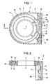
Fig. 1 is a plan view illustrating a multi-rotation angle detection device according to an example having a top cover removed; -
Fig. 2 is a sectional view taken along line II-II ofFig. 1 ; -
Fig. 3 is a side view of the multi-rotation angle detection device according to the example having a side cover removed; -
Fig. 4 is a table representing combinations of number of teeth between the first gear and the first driven gear, and the second gear and the second driven gear which are available for the multi-rotation angle detection device according to the example; -
Fig. 5 is a plan view illustrating a multi-rotation angle detection device as a modified example; -
Fig. 6 is a sectional view taken along line VI-VI ofFig. 5 ; -
Fig. 7 is a side view of the multi-rotation angle detection device according to the modified example having a side cover removed; -
Fig. 8 is a perspective view illustrating an arrangement of the first and the second driven gears with respect to a rotor of the multi-rotation angle detection device according to another modified example; -
Fig. 9 is a flowchart representing a process for detecting a rotating angle of the multi-rotation angle detection device according to the present invention; and -
Figs. 10A to 10C are graphs each representing a relationship between an absolute angle of the rotor of the multi-rotation angle detection device and an angular signal output from a magnetic detection element. - A mechanical structure of the multi-rotation angle detection device according to the embodiment will be described by taking examples.
- Referring to
Figs. 1 to 3 , a multi-rotation angle detection device according to the example has a first drivengear 13 and a second drivengear 14 disposed at the lower surface side of a flangedgear forming section 1a integrally formed with arotor 1. - That is, the multi-rotation angle detection device according to the example includes a
cylindrical rotor 1 attached to a rotating body such as a steering shaft so as to rotate together with the rotating body, and a housing (stator) 2 which is fixed to a not shown stator portion around the rotating body for rotatably holding therotor 1. Thehousing 2 is formed by combining acase 3, atop cover 4a and aside cover 4b to form an L-like side view as shown inFig. 2 . Each of therotor 1 and thehousing 2 is formed of a synthetic resin material. Especially polyacetal is used for forming therotor 1 for the purpose of providing smooth rotating operation and excellent sliding abrasion property. Upon production of the first drivengear 13 and the second drivengear 14 as described above, it is preferable to use the different material from the one for forming therotor 1. - The flanged
gear forming section 1a is integrally formed on the outer surface of therotor 1. Afirst gear 11 and asecond gear 12 each having different number of teeth are formed at the lower surface side of thegear forming section 1a concentrically with respect to the rotating axis of the rotating body, that is, the rotating axis Y-Y of therotor 1. Thefirst gear 11 which is formed at the outer circumference of thesecond gear 12, having the number of teeth larger than that of thesecond gear 12 is engaged with the first drivengear 13. Thesecond gear 12 which is formed at the inner circumference of thefirst gear 11, having the number of teeth smaller than that of thefirst gear 11 is engaged with the second drivengear 14. Referring toFigs. 1 and 2 , the first drivengear 13 and the second drivengear 14 are rotatably held in thecase 3. - The plane which includes the rotating axis Y-Y of the
rotor 1 is arranged to be orthogonal to a rotating axis X1-X1 of the first drivengear 13. Likewise, the plane which includes the rotating axis Y-Y of therotor 1 is arranged to be orthogonal to a rotating axis X2-X2 of the second drivengear 14. As a result, the rotating axis X1-X1 is positioned parallel to the rotating axis X2-X2. The gear for orthogonally crossed axis or orthogonally stagger axis may be employed for thefirst gear 11, the first drivengear 13 engaged therewith, thesecond gear 12, and the second drivengear 14 engaged therewith. As the gear for intersecting axis, a straight bevel gear or a spiral bevel type face gear may be employed. As the gear for orthogonal intersecting axis, a face gear may be employed. The appropriate gear is selected in accordance with the external configuration of the desired device. - The aforementioned structure allows the first driven
gear 13 and the second drivengear 14 to be arranged such that amagnet mount surface 13a of the first drivengear 13 and amagnet mount surface 14a of the second drivengear 14 are aligned in the same plane. This makes it possible to form the side configuration of thehousing 2 for storing the first and the second drivengears rotor 1 into substantially L-like shape, thus reducing the plane size of the multi-rotation angle detection device. Afirst magnet 18 is attached to themagnet mount surface 13a of the first drivengear 13, and asecond magnet 19 is attached to themagnet mount surface 14a of the second drivengear 14, respectively. Each of those first and thesecond magnets magnet mount surface 13a of the first drivengear 13 and themagnet mount surface 14a of the second drivengear 14, respectively. - A
circuit substrate 22 is provided at a position opposite themagnet mount surface 13a of the first drivengear 13 and themagnet mount surface 14a of the second drivengear 14 in thehousing 2. A firstmagnetic detection element 20 for detecting change in the magnetic field in association with the rotation of the first drivengear 13 is provided on thecircuit substrate 22 at the position opposite thefirst magnet 18. A secondmagnetic detection element 21 for detecting change in the magnetic field in association with the rotation of the second drivengear 14 is provided at the position opposite thesecond magnet 19. A GMR (Giant Magneto-Resistive) sensor which is unlikely to be influenced by the change in the magnetic field intensity and exhibits high temperature stability may be employed for thosemagnetic detection elements circuit substrate 22 is also provided with amicroprocessor 23 for calculating a rotating angle of therotor 1 based on the detection signals from the first and the secondmagnetic detection elements - Assuming that the maximum rotating number of the
rotor 1 is set to N (N:integer), and the gear ratio between thefirst gear 11 and the first drivengear 13 is set to n (n: integer), the number of teeth of thefirst gear 11 is obtained as being m times the value of N x n (m:integer). In the example, the absolute angle obtained while therotor 1 is making two left and right rotations, respectively from the neutral position is intended to be detected (maximum rotating number N = 4). In the case where the gear ratio between thefirst gear 11 and the first drivengear 13 is set to 2 (n=2), and the m is set to 8, 64 is obtained as the number of teeth by octuplicating the value of 4 x 2 (=8). - The number of teeth of the
second gear 12 is obtained as being m times the value of N x n-1 (m:integer). In the example, 56 is obtained as the number of teeth by octuplicating the value of 4 x 2 - 1 (=7). - Combination of the numbers of teeth of the
first gear 11 and thesecond gear 12 is not limited to the aforementioned example, and the values shown inFig. 4 may be employed. - Assuming that the
first gear 11 has the aforementioned structure, the number of teeth of the first drivengear 13 is obtained by multiplying N by the difference of the number of teeth between thefirst gear 11 and thesecond gear 12. In the example, N is set to 4, and the difference of the number of teeth is 8 (64-56). Therefore, the number of teeth of the first drivengear 13 becomes 32 (4 x 8). - Assuming that the
second gear 12 has the aforementioned structure, the number of teeth of the second drivengear 14 is obtained likewise the case of the first drivengear 13. In the example, the number of teeth of the second drivengear 14 becomes 32. - The multi-rotation angle detection device of the embodiment has the first driven
gear 13 and the second drivengear 14 disposed below thegear forming section 1a. Unlike the case for arranging the first and the second driven gears 13 and 14 on an outer circumference of thegear forming section 1a, the present structure may reduce the plane size L of thehousing 2. As themagnet mount surface 13a of the first drivengear 13 and themagnet mount surface 14a of the second drivengear 14 are arranged in the same plane, both the first and the secondmagnetic detection elements single circuit substrate 22, thus reducing the manufacturing cost of the multi-rotation angle detection device. - The multi-rotation angle detection device according to a modified example includes the first driven
gear 13 at the lower surface side of the flangedgear forming section 1a integrally formed with therotor 1, and the second drivengear 14 at the upper surface side of thegear forming section 1a as shown inFigs. 5 to 7 . In the modified example, thefirst gear 11 is formed at the lower surface side of thegear forming section 1a, and thesecond gear 12 is formed at the upper surface side. The first drivengear 13 and the second drivengear 14 are disposed in the same radius of thegear forming section 1a, and themagnet mount surface 13a of the first drivengear 13 and themagnet mount surface 14a of the second drivengear 14 are arranged in the same plane. In this example, thehousing 2 has substantially T-like side configuration as shown inFig. 6 . Other features of the modified example are the same as those of the multi-rotation angle detection device according to the example. The corresponding elements are designated with the same codes, and explanation thereof will be omitted. - As
Fig. 8 illustrates, the multi-rotation angle detection device according to another modified example includes the first drivengear 13 and the second drivengear 14 at the upper surface side of the flangedgear forming section 1a integrally formed with therotor 1. In the modified example, thefirst gear 11 and thesecond gear 12 are formed at the upper surface side of thegear forming section 1a. In this case, thehousing 2 has substantially L-like side configuration at the inverted side of the multi-rotation angle detection device of the example as described above. Other features are the same as those of the multi-rotation angle detection device of the example. The corresponding elements are designated with the same codes, and explanation thereof will be omitted. - The process for detecting the rotating angle, which is executed by the above-structured multi-rotation angle detection device will be described.
- Referring to
Fig. 10A , themicroprocessor 23 calculates a first angle signal A1 having the output value linearly changed from 0% to 100% while the first drivengear 13 is rotating at the angle from 0° to 360°, and a second angle signal A2 having the output value linearly changed from 0% to 100% while the second drivengear 14 is rotating at the angle from 0° to 360° based on output signals from the firstmagnetic detection element 20 and the secondmagnetic detection element 21. When each of the first drivengear 13 and the second drivengear 14 makes the second rotation, each output value irregularly returns to 0% to linearly increase the value again in association with each rotation of the respective drivengears - The
microprocessor 23 executes the arithmetic process for obtaining the absolute rotating angle of therotor 1 based on the first angle signal A1 and the second angle signal A2. The arithmetic process includes first step (S1) for obtaining a difference between detected values of the first angle signal A1 and the second angle signal A2, second step (S2) for correcting the difference, and third step (S3) for calculating the absolute angle of therotor 1. - As the first driven
gear 13 and the second drivengear 14 rotate at different rotating speeds with respect to the rotation of therotor 1, the values of rotating angles become different, resulting in the difference between the first angle signal A1 and the second angle signal A2. In first step (S1), as shown inFig. 10B , the output value of the second angle signal A2 is subtracted from the output value of the first angle signal A1 to obtain a difference signal A3. The difference signal A3 takes a different value depending on the absolute angle of therotor 1. When therotor 1 makes four rotations, the difference in the rotating angle between the first drivengear 13 and the second drivengear 14 corresponds to the single rotation, and then, the difference signal A3 becomes 0 again. - In second step (S2), when the difference signal A3 indicates the negative value, 100 is added to the difference value to calculate a correction signal A4 as shown in
Fig. 10C . The correction signal A4 corresponds to the absolute angle to be detected one-on-one over the entire range. As a result, the value linearly changes from 0% to 100%. - In third step (S3), the absolute angle of the
rotor 1 which makes more than one rotation, that is, the rotating body is detected based on the correction signal A4. - The method of detecting the rotating angle in case of using the multi-rotation angle detection device of the embodiment for detecting the rotating angle of the automotive steering shaft will be described.
- When the driver operates a steering wheel of the automobile, the
rotor 1 is rotated together with the steering wheel. Then the first drivengear 13 rotates via thefirst gear 11 and the second drivengear 14 rotates via thesecond gear 12. - Assuming that the gear ratio between the
first gear 11 and the first drivengear 13 is set to the value "2", the first drivengear 13 will make one rotation for each rotation of therotor 1 at 180°. The first angle signal A1 during the aforementioned period is expressed as a triangular wave which changes from 0% to 100%. The first drivengear 13 makes eight rotations while therotor 1 is making four rotations to change the absolute angle from 0° to 1440°. Accordingly, the resultant triangular wave forms eight cycles as shown inFig. 10A . Assuming that the gear ratio between thesecond gear 12 and the second drivengear 14 is set to the value "1.75", the second drivengear 14 will make seven rotations while therotor 1 is making 4 rotations. Accordingly, the second angle signal A2 expressed as the triangular wave forms seven cycles as a whole as shown inFig. 10A . - In first step (S1) where the first angle signal A1 and the second angle signal A2 are processed, the difference signal A3 as the output difference between the first angle signal A1 and the second angle signal A1 is calculated as shown in
Fig. 10B . As the difference signal A3 includes the negative range, the calculated value is corrected in second step (S2) to calculate the correction signal A4 as shown inFig. 10C . Then in third step (S3), the absolute angle of therotor 1 which makes more than one rotation, that is, the rotating body is detected based on the correction signal A4. - The multi-rotation angle detection device according to the example and the modified examples is structured to arrange the first and the second driven gears 13, 14 while having the first and the second rotating axes X1-X1 and X2-X2 thereof orthogonalized with respect to the plane which includes the rotating axis Y-Y of the
rotor 1. The magnet mount surfaces 13a and 14a of the first and the second driven gears 13 and 14 may be arranged parallel to the plane which includes the rotating axis Y-Y of therotor 1 so as to reduce the plane size of the multi-rotation angle detection device. As therotor 1 rotates, the first drivengear 13 and the second drivengear 14 are driven and rotated such that each rotating operation of the respective drivengears magnetic detection elements first gear 11 and the first drivengear 13, or any one of teeth of thesecond gear 12 and the second drivengear 14 is broken or lost, the detection signal from the firstmagnetic detection element 20 corresponding to the first drivengear 13 is compared with the detection signal from the secondmagnetic detection element 21 corresponding to the second drivengear 14 for detecting the failure, resulting in excellent reliability and fail-safe property. - The present invention is not limited to the aforementioned embodiment, but may be changed into various forms without departing from the scope of the present invention. For example, the multi-rotation angle detection device as the example is employed for the automobile. However, it is not limited to the use for the automobile but may be applied to other types of vehicle such as train and boat. In the respective examples, the gear ratio between the
first gear 11 and the first drivengear 13 is set to the value "2", and the gear ratio between thesecond gear 12 an the second drivengear 14 is set to the value "1.75". However, those ratios may be set to the other values. - The present invention is applicable for detecting the rotating angle of the steering shaft in the automobile.
Claims (2)
- A multi-rotation angle detection device comprising:a rotor (1) having a first gear (11) and a second gear (12) each with a different number of teeth, which are concentrically provided for a flanged gear forming section (1a) ;a first driven gear (13) having a first rotating axis orthogonalized to a plane including a rotating axis of the rotor (1), and engaged with the first gear (11);a second driven gear (14) having a second rotating axis orthogonalized to the plane, and engaged with the second gear (12);a first magnet (18) attached to the first driven gear (13);a second magnet (19) attached to the second driven gear (14) ;a circuit substrate (22) having the first driven gear (13) and the second driven gear (14);a first magnetic detection element (20) disposed at a position opposited the first magnet (18) above the circuit substrate (22);a second magnetic detection element (21) disposed at a position opposited the second magnet (19) above the circuit substrate (22); anda housing (2) storing the rotor (1), the first driven gear (13), the second driven gear (14), the first magnet (18), the second magnet (19), the circuit substrate (22), the first magnetic detection element (20), and the second magnetic detection element (21).
- The multi-rotation angle detection device according to Claim 1, wherein the first gear (11) and the second gear (12) disposed at a lower surface side of the circuit substrate (22).
Applications Claiming Priority (1)
| Application Number | Priority Date | Filing Date | Title |
|---|---|---|---|
| JP2009122382A JP2010269667A (en) | 2009-05-20 | 2009-05-20 | Multi-rotation angle detection device |
Publications (2)
| Publication Number | Publication Date |
|---|---|
| EP2253939A2 true EP2253939A2 (en) | 2010-11-24 |
| EP2253939A3 EP2253939A3 (en) | 2014-03-05 |
Family
ID=42734775
Family Applications (1)
| Application Number | Title | Priority Date | Filing Date |
|---|---|---|---|
| EP10161247.1A Withdrawn EP2253939A3 (en) | 2009-05-20 | 2010-04-28 | Multi-rotation angle detection device |
Country Status (4)
| Country | Link |
|---|---|
| US (1) | US8283917B2 (en) |
| EP (1) | EP2253939A3 (en) |
| JP (1) | JP2010269667A (en) |
| CN (1) | CN101893423B (en) |
Cited By (2)
| Publication number | Priority date | Publication date | Assignee | Title |
|---|---|---|---|---|
| US20100052937A1 (en) * | 2008-09-01 | 2010-03-04 | Smk Corporation | Remote control transmitting device |
| WO2012119732A1 (en) * | 2011-03-04 | 2012-09-13 | Auma Riester Gmbh + Co. Kg | Measurement device for detecting the absolute angle of rotation of a rotating measurement object |
Families Citing this family (11)
| Publication number | Priority date | Publication date | Assignee | Title |
|---|---|---|---|---|
| JP4893721B2 (en) * | 2008-10-06 | 2012-03-07 | トヨタ自動車株式会社 | Rotation angle detector |
| KR101829057B1 (en) * | 2010-12-21 | 2018-02-13 | 엘지이노텍 주식회사 | Angle sensor |
| TWI500907B (en) * | 2011-01-07 | 2015-09-21 | Oriental Motor Co Ltd | Apparatus for detecting multi-turn absolute rotation angle and method for detecting the same |
| JP5597158B2 (en) * | 2011-04-11 | 2014-10-01 | ヤマハ発動機株式会社 | Component mounting equipment |
| CN103359167A (en) * | 2012-03-28 | 2013-10-23 | 比亚迪股份有限公司 | Method and device for measuring steering wheel rotation angle |
| CN102749026B (en) * | 2012-07-10 | 2015-01-21 | 万向钱潮(上海)汽车系统有限公司 | Detection device and method for absolute-type multi-circle rotation angle |
| DK2928865T3 (en) | 2012-12-07 | 2018-06-18 | Merck Sharp & Dohme | BIOCATALYTIC TRANSAMINATION PROCEDURE |
| CN109891186B (en) * | 2016-09-23 | 2022-02-01 | 哈姆林电子(苏州)有限公司 | Integrated double-rotation position sensor |
| CN110753684A (en) | 2017-04-24 | 2020-02-04 | 特沙诺有限公司 | Method for producing nilapali |
| CN107356193A (en) * | 2017-08-02 | 2017-11-17 | 武汉理岩控制技术有限公司 | A kind of detection means of rotational angle |
| US11637482B2 (en) * | 2020-10-08 | 2023-04-25 | Analog Devices International Unlimited Company | Magnetic sensor system for motor control |
Citations (1)
| Publication number | Priority date | Publication date | Assignee | Title |
|---|---|---|---|---|
| JPH11500828A (en) | 1995-02-28 | 1999-01-19 | ローベルト ボツシユ ゲゼルシヤフト ミツト ベシユレンクテル ハフツング | Method and apparatus for measuring angle in rotating body |
Family Cites Families (10)
| Publication number | Priority date | Publication date | Assignee | Title |
|---|---|---|---|---|
| JP4209155B2 (en) * | 2002-03-05 | 2009-01-14 | アルプス電気株式会社 | Rotation angle detector |
| JP2005156163A (en) * | 2003-11-20 | 2005-06-16 | Matsushita Electric Ind Co Ltd | Rotation angle detector |
| JP2005166460A (en) * | 2003-12-03 | 2005-06-23 | Alps Electric Co Ltd | Rotary electric component |
| JP2006017663A (en) * | 2004-07-05 | 2006-01-19 | Alps Electric Co Ltd | Rotation-angle sensitive device |
| JP2006234573A (en) * | 2005-02-24 | 2006-09-07 | Tokai Rika Co Ltd | Apparatus for detecting rotation angle |
| JP4607049B2 (en) * | 2006-02-23 | 2011-01-05 | 株式会社デンソー | Rotation angle detector |
| JP2008026039A (en) * | 2006-07-19 | 2008-02-07 | Matsushita Electric Ind Co Ltd | Rotation angle detector |
| CN200996830Y (en) * | 2006-12-14 | 2007-12-26 | 吴忠仪表股份有限公司 | Non-contact and magnetic-inductive senser of angular displacement |
| JP4992516B2 (en) * | 2007-04-02 | 2012-08-08 | パナソニック株式会社 | Rotation angle detector |
| CN101706250A (en) * | 2009-09-22 | 2010-05-12 | 张永生 | Absolute intersection angle measuring device with large scale and high accuracy |
-
2009
- 2009-05-20 JP JP2009122382A patent/JP2010269667A/en not_active Withdrawn
-
2010
- 2010-04-28 EP EP10161247.1A patent/EP2253939A3/en not_active Withdrawn
- 2010-05-14 US US12/780,427 patent/US8283917B2/en active Active
- 2010-05-18 CN CN2010101835433A patent/CN101893423B/en active Active
Patent Citations (1)
| Publication number | Priority date | Publication date | Assignee | Title |
|---|---|---|---|---|
| JPH11500828A (en) | 1995-02-28 | 1999-01-19 | ローベルト ボツシユ ゲゼルシヤフト ミツト ベシユレンクテル ハフツング | Method and apparatus for measuring angle in rotating body |
Cited By (4)
| Publication number | Priority date | Publication date | Assignee | Title |
|---|---|---|---|---|
| US20100052937A1 (en) * | 2008-09-01 | 2010-03-04 | Smk Corporation | Remote control transmitting device |
| US8138942B2 (en) * | 2008-09-01 | 2012-03-20 | Smk Corporation | Remote control transmitting device |
| WO2012119732A1 (en) * | 2011-03-04 | 2012-09-13 | Auma Riester Gmbh + Co. Kg | Measurement device for detecting the absolute angle of rotation of a rotating measurement object |
| US9482556B2 (en) | 2011-03-04 | 2016-11-01 | Auma Riester Gmbh + Co. Kg | Measuring system for registering the absolute rotation angle of a rotating, measured object |
Also Published As
| Publication number | Publication date |
|---|---|
| JP2010269667A (en) | 2010-12-02 |
| CN101893423B (en) | 2013-01-02 |
| US20100295541A1 (en) | 2010-11-25 |
| EP2253939A3 (en) | 2014-03-05 |
| CN101893423A (en) | 2010-11-24 |
| US8283917B2 (en) | 2012-10-09 |
Similar Documents
| Publication | Publication Date | Title |
|---|---|---|
| US8283917B2 (en) | Multi-rotation angle detection device | |
| JP5611238B2 (en) | Relative angle detection device, rotation angle detection device, relative angle detection method, and rotation angle detection method | |
| AU752711B2 (en) | Sensor array for detecting rotation angle and/or torque | |
| US7775129B2 (en) | Rotation angle sensor | |
| US10647353B2 (en) | Electromechanical power steering system, method for determining an absolute angle of rotation, and method for calibrating a measuring device for measuring an absolute angle of rotation | |
| JP4562355B2 (en) | Rotation angle detection device and rotation angle detection method | |
| US7535219B2 (en) | Rotation angle detector | |
| JP2007232617A (en) | Rotary angle detector and its initial setting method | |
| JP2010008270A (en) | Rotation angle detection device | |
| EP1503171A2 (en) | Angle sensor | |
| JP2007285799A (en) | Rotation angle detector | |
| JP2004279065A (en) | Rotation angle detecting apparatus | |
| JP2010236935A (en) | Rotation angle detection device | |
| JP4607033B2 (en) | Rotation angle detector | |
| CN101416037A (en) | Rotation angle detector | |
| JP2004226355A (en) | Rotation angle detecting device | |
| JP4622641B2 (en) | Rotation angle detector | |
| JP5134996B2 (en) | Rotation angle detector | |
| JP2010271180A (en) | Multiple rotation angle detector | |
| JP2011022074A (en) | Multi-rotation angle detection device | |
| JP6280980B2 (en) | Torque detection device | |
| JP5706355B2 (en) | Rotation angle detector | |
| JP7848436B2 (en) | encoder | |
| JP2013120090A (en) | Rotation angle detector | |
| JP2013186033A (en) | Rotation angle detector |
Legal Events
| Date | Code | Title | Description |
|---|---|---|---|
| PUAI | Public reference made under article 153(3) epc to a published international application that has entered the european phase |
Free format text: ORIGINAL CODE: 0009012 |
|
| AK | Designated contracting states |
Kind code of ref document: A2 Designated state(s): AT BE BG CH CY CZ DE DK EE ES FI FR GB GR HR HU IE IS IT LI LT LU LV MC MK MT NL NO PL PT RO SE SI SK SM TR |
|
| AX | Request for extension of the european patent |
Extension state: AL BA ME RS |
|
| PUAL | Search report despatched |
Free format text: ORIGINAL CODE: 0009013 |
|
| AK | Designated contracting states |
Kind code of ref document: A3 Designated state(s): AT BE BG CH CY CZ DE DK EE ES FI FR GB GR HR HU IE IS IT LI LT LU LV MC MK MT NL NO PL PT RO SE SI SK SM TR |
|
| AX | Request for extension of the european patent |
Extension state: AL BA ME RS |
|
| RIC1 | Information provided on ipc code assigned before grant |
Ipc: G01D 5/14 20060101AFI20140127BHEP |
|
| STAA | Information on the status of an ep patent application or granted ep patent |
Free format text: STATUS: THE APPLICATION IS DEEMED TO BE WITHDRAWN |
|
| 18D | Application deemed to be withdrawn |
Effective date: 20140906 |