EP2253887A2 - Advanced quench pattern combustor - Google Patents
Advanced quench pattern combustor Download PDFInfo
- Publication number
- EP2253887A2 EP2253887A2 EP10163039A EP10163039A EP2253887A2 EP 2253887 A2 EP2253887 A2 EP 2253887A2 EP 10163039 A EP10163039 A EP 10163039A EP 10163039 A EP10163039 A EP 10163039A EP 2253887 A2 EP2253887 A2 EP 2253887A2
- Authority
- EP
- European Patent Office
- Prior art keywords
- quench
- combustor
- aperture
- distance
- apertures
- Prior art date
- Legal status (The legal status is an assumption and is not a legal conclusion. Google has not performed a legal analysis and makes no representation as to the accuracy of the status listed.)
- Granted
Links
Images



Classifications
-
- F—MECHANICAL ENGINEERING; LIGHTING; HEATING; WEAPONS; BLASTING
- F23—COMBUSTION APPARATUS; COMBUSTION PROCESSES
- F23R—GENERATING COMBUSTION PRODUCTS OF HIGH PRESSURE OR HIGH VELOCITY, e.g. GAS-TURBINE COMBUSTION CHAMBERS
- F23R3/00—Continuous combustion chambers using liquid or gaseous fuel
- F23R3/02—Continuous combustion chambers using liquid or gaseous fuel characterised by the air-flow or gas-flow configuration
- F23R3/04—Air inlet arrangements
- F23R3/06—Arrangement of apertures along the flame tube
Definitions
- This disclosure relates generally to combustors for gas turbine engines and, more particularly, to the configuration of quench apertures in a combustor for a gas turbine engine.
- a typical combustor in a gas turbine engine has a combustion chamber having a forward section, an intermediate section (sometimes referred to as a "quench section") and an aft section.
- the combustion chamber includes a forward bulkhead, an inner annular wall and an outer annular wall which extend from the forward bulkhead to an exhaust outlet.
- the forward section of the combustion chamber includes a plurality of circumferentially disposed nozzles and swirlers.
- the intermediate section of the combustion chamber includes a plurality of equally spaced quench apertures circumferentially disposed in the inner and outer walls.
- thermal hotspot is a region in a thermal profile where the temperature is significantly elevated as compared to the surrounding area of the profile.
- the ignited fuel-air mixture flows from the forward section into the intermediate section where the mixture is quenched by additional air (“quench air”) flowing into the chamber from the inner and the outer quench apertures.
- quench air performs two functions: it provides oxygen for completion of combustion, and it is used to affect the shape of the thermal profile.
- the quenched mixture flows from the intermediate section, through the aft section, and out of the combustor through the combustor exit.
- the exhausted combusted mixture may still exhibit significant thermal hotspots which reduce the efficiency of the engine.
- a combustor for a gas turbine engine comprising a forward bulkhead having a plurality of circumferentially disposed injector apertures; an inner radial combustor wall attached to and extending axially out from the forward bulkhead; and an outer radial combustor wall attached to and extending axially out from the forward bulkhead; wherein at least one of the inner radial combustor wall and the outer radial combustor wall includes a plurality of quench aperture sets, each quench aperture set including a plurality of quench apertures, wherein adjacent quench apertures included within each quench aperture set are separated by an intraset distance, wherein adjacent quench apertures in adjacent quench aperture sets are separated by an interset distance, and wherein the intraset distance is different than the interset distance; and wherein the outer radial combustor wall is disposed radially outside the inner radial combustor wall defining an annular combustion region therebetween.
- a combustor for a gas turbine engine includes a forward bulkhead, an inner radial combustor wall, and an outer radial combustor wall.
- the bulkhead includes a plurality of circumferentially disposed injector apertures.
- the inner radial combustor wall is attached to, and extends axially out from, the forward bulkhead.
- the inner radial combustor wall includes a plurality of inner quench aperture sets. Each inner quench aperture set includes a first inner quench aperture and a second inner quench aperture separated from each other by an inner intraset distance. Each inner quench aperture set is separated from an adjacent inner quench aperture set by an inner interset distance.
- the inner interset distance is different from the inner intraset distance.
- the outer radial combustor wall is attached to and extends axially out from the forward bulkhead.
- the outer radial combustor wall includes a plurality of circumferentially disposed outer quench apertures.
- the outer radial combustor wall is disposed radially outside of the inner radial combustor wall, thereby defining an annular combustion region therebetween.
- a combustor for a gas turbine engine includes a forward bulkhead, an inner radial combustor wall, and an outer radial combustor wall.
- the bulkhead includes a plurality of circumferentially disposed injector apertures.
- the inner radial combustor wall is attached to, and extends axially out from, the forward bulkhead.
- the inner radial combustor wall includes a plurality of circumferentially disposed inner quench apertures.
- the outer radial combustor wall is attached to, and extends axially out from the forward bulkhead.
- the outer radial combustor wall includes a plurality of outer quench aperture sets.
- Each outer quench aperture set includes a middle quench aperture disposed between a first outer quench aperture and a second outer quench aperture.
- the middle quench aperture is spaced equidistant from the first and second outer quench apertures within that set by an outer intraset distance.
- Each outer quench aperture set is separated from an adjacent outer quench aperture set by an outer interset distance.
- the outer interset distance is different from the outer intraset distance.
- the outer radial combustor wall is disposed radially outside of the inner radial combustor wall, thereby defining an annular combustion region therebetween.
- FIG. 1 is a diagrammatic illustration of one embodiment of a combustor 20 for a gas turbine engine.
- the combustor 20 includes a forward bulkhead 22, a plurality of swirlers 24, an inner radial combustor wall 26, and an outer radial combustor wall 28.
- the forward bulkhead 22 extends between an inner end 30 and an outer end 32, and includes a plurality of injector mounting apertures 34.
- the injector apertures 34 are configured in and typically uniformly spaced around the circumference of the forward bulkhead 22.
- Each injector aperture 34 is adapted to mount a swirler 24 operable to inject and swirl air for combustion into the combustor 20.
- Each swirler 24 includes a fuel nozzle 35.
- the inner radial combustor wall 26 is attached to the inner end 30 of the forward bulkhead 22, and the outer radial combustor wall 28 is attached to the outer end 32 of the forward bulkhead 22.
- the inner and outer walls 26, 28 define an annular combustion region 36 and a combustor outlet 37.
- the fuel nozzles 35 may be aligned with or between quench apertures disposed within the combustor walls 26, 28.
- the inner radial combustor wall 26 is an annular section extending between a first end 38 and a second end 40.
- the inner radial combustor wall 26 includes a plurality of circumferentially disposed inner quench apertures 42, 44 located at an axial distance 46 from the forward bulkhead 22.
- the inner quench apertures 42, 44 are configured for radially injecting a quantity of quench air for mixing and combusting with an axially traveling mixture of swirled air and fuel. Although it can vary by application, the quantity of quench air injected through the inner quench apertures 42, 44 is typically greater than the quantity of air injected through the air swirlers 24.
- the inner radial combustor wall 26 further includes a plurality of circumferentially and axially disposed cooling apertures (not shown) configured to cool the inner radial combustor wall 26. As the name implies, these cooling apertures provide a different function than the quench apertures.
- the inner quench apertures 42, 44 are disposed within the inner radial combustor wall 26 in a plurality of inner quench aperture sets.
- Each inner quench aperture set includes a first quench aperture 42 and a second quench aperture 44 separated from each other by an intraset distance 48.
- the intraset distance 48 is the distance between centers 51 of the quench apertures 42, 44 in a particular quench aperture set.
- Each quench aperture set is separated from an adjacent quench aperture set by an interset distance 50.
- the interset distance 50 is the distance between the centers 51 of adjacent quench apertures in different sets.
- the interset distance 50 may be equal to or greater than the intraset distance 48, depending upon the particular combustor embodiment.
- the first and the second quench apertures 42, 44 have approximately equal diameters sized to inject a portion of the second quantity of air 52.
- the interset distance 50, the intraset distance 48 and/or the diameters of the quench apertures 42, 44 in the inner radial combustor wall 26 are selected to create radially extending flow patterns that influence the axial flow pattern of air, unburned fuel, and combustion products (hereinafter referred to as the "axial air") within the combustor 20.
- the axial flow pattern of the axially injected fuel is influenced by the impingement of the radially injected quench air.
- the ability to selectively influence the axial flow pattern is particularly desirable in applications where the air/fuel mix delivered from the nozzles 35 is localized in discrete positions around the circumference of the combustor, and therefore not distributed in a circumferentially uniform manner.
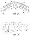
- FIGS. 2 and 3 diagrammatically show an inner radial combustor wall 26 having sets of quench apertures 42, 44 having an interset distance 50 that is greater than the intraset distance 48.
- FIGS. 4 and 5 in contrast, diagrammatically show an inner radial combustor wall 58 having uniformly spaced quench apertures 53 (i.e., interset distance 54 equals intraset distance 56). If the number of quench apertures disposed in the inner radial combustor walls 26, 58 is the same, the amount of axial air 60 flowing between the uniformly spaced radial quench air jets 62 ( FIG. 4 ) is greater than the amount of axial air 64 that will flow between the radial quench air jets 52 associated with the shorter intraset distance 48.
- the first and the second quench apertures 42, 44 may be sized to increase or decrease the impinging and/or dispersing effect on the axially injected fuel by increasing or decreasing the diameter of the first and the second quench apertures 42, 44. It should be noted that the aforesaid is an example of only one embodiment of the combustor 20 and the present invention is not limited to this particular embodiment.
- the outer radial combustor wall 28 is an annular section extending between a first end 70 and a second end 72.
- the outer radial combustor wall 28 includes a plurality of circumferentially disposed outer quench apertures 74, 76, 78 located at an axial distance 80 from the first end 70 of the outer radial combustor wall 28.
- the outer quench apertures 74, 76, 78 are configured for radially injecting a quantity of quench air for mixing and combusting with the axially injected fuel.
- the quench air injected through the outer quench apertures 74, 76, 78 is typically greater than the axial air passing through the combustor 20.
- the quantity of quench air injected through the outer quench apertures 74, 76, 78 is approximately equal to the quantity of quench air injected through the inner quench apertures 42, 44.
- the outer radial combustor wall 28 includes a plurality of cooling apertures (not shown) configured to cool the combustor 20.
- the outer quench apertures are disposed within the outer radial combustor wall 28 in a plurality of quench aperture sets.
- Each quench aperture set includes a middle quench aperture 74 disposed between a first quench aperture 76 and a second quench aperture 78.
- the middle quench aperture 74 is equidistant between the first quench aperture 76 and the second quench aperture 78.
- the intraset distance 82 is measured between the center 84 of the middle aperture 74 and the center 86, 88 of either the first or second aperture 76, 78.
- the interset distance 90 is the distance between the centers 86, 88 of adjacent quench apertures in different sets.
- the interset distance 90 may be equal to or different than the intraset distance 82.
- the first and the second quench apertures 76, 78 have approximately equal diameters, and the middle aperture 74 has a larger diameter than the first and second apertures 76, 78.
- the middle, first, and the second outer quench apertures 74, 76, 78 may be sized to increase or decrease the impinging and/or dispersing effect on the axially injected fuel by increasing or decreasing the diameter thereof.
- the diameters of the first and the second apertures 76, 78 in the outer radial combustor wall 28 may be equal to or smaller than the first and the second apertures 42, 44 in the inner radial combustor wall 26.
- the interset distance 90, the intraset distance 82 and/or the diameters of the quench apertures 74, 76, 78 in the outer radial combustor wall 28 are selected to create radially extending flow patterns that influence the axial flow within the combustor 20.
- the axial flow pattern of the axially injected fuel is influenced by the impingement of the radially injected outer quench air.
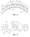
- FIGS. 6 and 7 diagrammatically show an outer radial combustor wall 28 having sets of quench apertures 74, 76, 78 having an interset distance 90 that is greater than the intraset distance 82.
- FIGS. 8 and 9 diagrammatically show an outer radial combustor wall 97 having uniformly spaced quench apertures 99, 100 (i.e., interset distance 102 equal to the intraset distance 104).
- the axial flow pattern associated with an outer radial combustor wall 97 that includes uniformly spaced quench apertures 99, 100 is such that at least portions of the axial air flows 106, 108 between the outer radial quench air jets 110 will remain substantially unmixed.
- the present invention combustor can include an inner radial combustor wall 26 with quench apertures 42, 44 disposed in sets that have an interset distance 50 that is equal to or greater than an intraset distance 48.
- the present invention combustor is also described as having an outer radial combustor wall 28 with quench apertures 74, 76, 78 disposed in sets that have an interset distance 90 that is equal to or greater than an intraset distance 82.
- the wall 26, 28 embodiments having quench aperture sets having unequal interset and intraset distances can be used with an opposing wall embodiment having uniformly spaced quench apertures, or an opposing wall embodiment also having quench aperture sets with unequal interset and intraset distances.
- the outer radial combustor wall 28 has quench apertures having an interset distance 90 that is approximately equal to the intraset distance 82, and an inner combustor wall 26 has quench apertures having an interset distance 50 that is greater than the intraset distance 48.
- the outer radial combustor wall has quench apertures with an interset distance 90 that is greater than the intraset distance 82, and the inner radial combustor wall 26 has quench apertures with an interset distance 50 that is approximately equal to the intraset distance 48.
- the present invention is not limited to these examples.
- each nozzle 35 in the forward bulkhead 22 injects a quantity of fuel into the combustion region of the combustor 20 in a substantially axial direction. It should be noted that a stoichiometric or higher quantity of air is needed to fully combust all the fuel axially injected from the nozzles. A first portion of the air necessary for combustion is injected into the combustion region from a front end region 111 (e.g., the swirlers 24) to provide a rich fuel-air mixture.
- the ignition source (not shown) initiates the combustion of the fuel-air mixture, creating thermal hotspots circumferentially aligned with the nozzles 35.
- a thermal hotspot is a region in a thermal profile where the temperature is significantly elevated as compared to the surrounding area of the profile.
- the partially combusted fuel-air mixture travels substantially axially through the combustion region 36 towards the inner and outer quench apertures. Additional quantities of air (i.e., "quench air”) are radially injected into the combustion region from the inner and outer quench apertures.
- quench air Additional quantities of air
- the quench apertures in one or both of the inner and outer radial combustor walls 26, 28 may be arranged such that the intraset distances 48, 82 are less than the interset distances 50, 90.
- the injected quench air impinges upon, and mixes with, the partially combusted fuel-air mixture as it travels between the inner and outer quench apertures.
- the quench apertures 42, 44 have a smaller intraset distance 48 than an interset distance 50, and the quench apertures are positioned such that the space between them is aligned with a nozzle 35, the radial jets 52 through the apertures 42, 44 promote more uniform circumferential distribution of the axial air as is diagrammatically shown in FIG. 3 .
- the radial jet through the middle aperture 74 promotes more uniform circumferential distribution of the axial air as is diagrammatically shown in FIG. 7 .
- the impinging air also affects the radial position of the partially combusted fuel-air mixture.
- the resulting axial air profile produces a more uniform thermal profile around the circumference of the combustor 20 with controlled radial positioning.
Landscapes
- Engineering & Computer Science (AREA)
- Chemical & Material Sciences (AREA)
- Combustion & Propulsion (AREA)
- Mechanical Engineering (AREA)
- General Engineering & Computer Science (AREA)
- Turbine Rotor Nozzle Sealing (AREA)
Abstract
Description
- This disclosure relates generally to combustors for gas turbine engines and, more particularly, to the configuration of quench apertures in a combustor for a gas turbine engine.
- A typical combustor in a gas turbine engine has a combustion chamber having a forward section, an intermediate section (sometimes referred to as a "quench section") and an aft section. The combustion chamber includes a forward bulkhead, an inner annular wall and an outer annular wall which extend from the forward bulkhead to an exhaust outlet. The forward section of the combustion chamber includes a plurality of circumferentially disposed nozzles and swirlers. The intermediate section of the combustion chamber includes a plurality of equally spaced quench apertures circumferentially disposed in the inner and outer walls.
- In operation, fuel from the nozzles is mixed with air from the swirlers and ignited by an ignition source in the forward section of the combustion chamber creating thermal hotspots circumferentially aligned with the nozzles. As known in the art, a thermal hotspot is a region in a thermal profile where the temperature is significantly elevated as compared to the surrounding area of the profile. The ignited fuel-air mixture flows from the forward section into the intermediate section where the mixture is quenched by additional air ("quench air") flowing into the chamber from the inner and the outer quench apertures. The quench air performs two functions: it provides oxygen for completion of combustion, and it is used to affect the shape of the thermal profile. The quenched mixture flows from the intermediate section, through the aft section, and out of the combustor through the combustor exit. However, the exhausted combusted mixture may still exhibit significant thermal hotspots which reduce the efficiency of the engine.
- According to the invention, there is provided a combustor for a gas turbine engine, comprising a forward bulkhead having a plurality of circumferentially disposed injector apertures; an inner radial combustor wall attached to and extending axially out from the forward bulkhead; and an outer radial combustor wall attached to and extending axially out from the forward bulkhead; wherein at least one of the inner radial combustor wall and the outer radial combustor wall includes a plurality of quench aperture sets, each quench aperture set including a plurality of quench apertures, wherein adjacent quench apertures included within each quench aperture set are separated by an intraset distance, wherein adjacent quench apertures in adjacent quench aperture sets are separated by an interset distance, and wherein the intraset distance is different than the interset distance; and wherein the outer radial combustor wall is disposed radially outside the inner radial combustor wall defining an annular combustion region therebetween.
- According to an aspect of the present invention, a combustor for a gas turbine engine is provided. The combustor includes a forward bulkhead, an inner radial combustor wall, and an outer radial combustor wall. The bulkhead includes a plurality of circumferentially disposed injector apertures. The inner radial combustor wall is attached to, and extends axially out from, the forward bulkhead. The inner radial combustor wall includes a plurality of inner quench aperture sets. Each inner quench aperture set includes a first inner quench aperture and a second inner quench aperture separated from each other by an inner intraset distance. Each inner quench aperture set is separated from an adjacent inner quench aperture set by an inner interset distance. The inner interset distance is different from the inner intraset distance. The outer radial combustor wall is attached to and extends axially out from the forward bulkhead. The outer radial combustor wall includes a plurality of circumferentially disposed outer quench apertures. The outer radial combustor wall is disposed radially outside of the inner radial combustor wall, thereby defining an annular combustion region therebetween.
- According to another aspect of the present invention, a combustor for a gas turbine engine is provided. The combustor includes a forward bulkhead, an inner radial combustor wall, and an outer radial combustor wall. The bulkhead includes a plurality of circumferentially disposed injector apertures. The inner radial combustor wall is attached to, and extends axially out from, the forward bulkhead. The inner radial combustor wall includes a plurality of circumferentially disposed inner quench apertures. The outer radial combustor wall is attached to, and extends axially out from the forward bulkhead. The outer radial combustor wall includes a plurality of outer quench aperture sets. Each outer quench aperture set includes a middle quench aperture disposed between a first outer quench aperture and a second outer quench aperture. The middle quench aperture is spaced equidistant from the first and second outer quench apertures within that set by an outer intraset distance. Each outer quench aperture set is separated from an adjacent outer quench aperture set by an outer interset distance. The outer interset distance is different from the outer intraset distance. The outer radial combustor wall is disposed radially outside of the inner radial combustor wall, thereby defining an annular combustion region therebetween.
-
-
FIG. 1 is a diagrammatic illustration of one embodiment of a combustor. -
FIG. 2 is a diagrammatic illustration of axial and radial flows through a cross-section of a portion of the combustor inFIG. 1 . -
FIG. 3 is a diagrammatic illustration of the axial and the radial flows through a section of the portion of the combustor inFIG. 2 . -
FIG. 4 is a diagrammatic illustration of axial and radial flows through a cross-section of a portion of a combustor. -
FIG. 5 is a diagrammatic illustration of the axial and the radial flows through a section of the portion of the combustor inFIG. 4 . -
FIG. 6 is a diagrammatic illustration of axial and radial flows through a cross-section of a portion of the combustor inFIG. 1 . -
FIG. 7 is a diagrammatic illustration of the axial and the radial flows through a section of the portion of the combustor inFIG. 6 . -
FIG. 8 is a diagrammatic illustration of axial and radial flows through a cross-section of a portion of a combustor. -
FIG. 9 is a diagrammatic illustration of the axial and the radial flows through a section of the portion of the combustor inFIG. 8 . -
FIG. 1 is a diagrammatic illustration of one embodiment of acombustor 20 for a gas turbine engine. Thecombustor 20 includes aforward bulkhead 22, a plurality ofswirlers 24, an innerradial combustor wall 26, and an outerradial combustor wall 28. - The
forward bulkhead 22 extends between aninner end 30 and anouter end 32, and includes a plurality ofinjector mounting apertures 34. Theinjector apertures 34 are configured in and typically uniformly spaced around the circumference of theforward bulkhead 22. Eachinjector aperture 34 is adapted to mount aswirler 24 operable to inject and swirl air for combustion into thecombustor 20. Eachswirler 24 includes afuel nozzle 35. The innerradial combustor wall 26 is attached to theinner end 30 of theforward bulkhead 22, and the outerradial combustor wall 28 is attached to theouter end 32 of theforward bulkhead 22. The inner andouter walls annular combustion region 36 and acombustor outlet 37. As will be explained below, thefuel nozzles 35 may be aligned with or between quench apertures disposed within thecombustor walls - The inner
radial combustor wall 26 is an annular section extending between afirst end 38 and asecond end 40. The innerradial combustor wall 26 includes a plurality of circumferentially disposedinner quench apertures axial distance 46 from theforward bulkhead 22. Theinner quench apertures inner quench apertures air swirlers 24. In some embodiments, the innerradial combustor wall 26 further includes a plurality of circumferentially and axially disposed cooling apertures (not shown) configured to cool the innerradial combustor wall 26. As the name implies, these cooling apertures provide a different function than the quench apertures. - In the embodiment in
FIGS. 2 and 3 , the inner quenchapertures radial combustor wall 26 in a plurality of inner quench aperture sets. Each inner quench aperture set includes a first quenchaperture 42 and a second quenchaperture 44 separated from each other by anintraset distance 48. Theintraset distance 48 is the distance betweencenters 51 of the quenchapertures interset distance 50. Theinterset distance 50 is the distance between thecenters 51 of adjacent quench apertures in different sets. Theinterset distance 50 may be equal to or greater than theintraset distance 48, depending upon the particular combustor embodiment. In the embodiment shown inFIGS. 2 and 3 , the first and the second quenchapertures air 52. - The
interset distance 50, theintraset distance 48 and/or the diameters of the quenchapertures radial combustor wall 26 are selected to create radially extending flow patterns that influence the axial flow pattern of air, unburned fuel, and combustion products (hereinafter referred to as the "axial air") within thecombustor 20. The axial flow pattern of the axially injected fuel is influenced by the impingement of the radially injected quench air. The ability to selectively influence the axial flow pattern is particularly desirable in applications where the air/fuel mix delivered from thenozzles 35 is localized in discrete positions around the circumference of the combustor, and therefore not distributed in a circumferentially uniform manner.FIGS. 2 and 3 diagrammatically show an innerradial combustor wall 26 having sets of quenchapertures interset distance 50 that is greater than theintraset distance 48.FIGS. 4 and 5 , in contrast, diagrammatically show an innerradial combustor wall 58 having uniformly spaced quench apertures 53 (i.e.,interset distance 54 equals intraset distance 56). If the number of quench apertures disposed in the innerradial combustor walls axial air 60 flowing between the uniformly spaced radial quench air jets 62 (FIG. 4 ) is greater than the amount ofaxial air 64 that will flow between the radial quenchair jets 52 associated with theshorter intraset distance 48. This is particularly so when flow from thenozzles 35 is locally concentrated at discrete circumferential positions which are aligned between the quenchapertures apertures 53. Theaxial air 66 traveling around the uniformly spaced radially quench air jets 62 (FIG. 5 ) is less than the amount ofaxial air 68 that will flow around the radial quenchair jets 52 associated with the shorter intraset distance 48 (FIG. 3 ). As a result, the axialair flow pattern FIGS. 2 and 3 is more circumferentially uniform and mixed, than is the axialair flow pattern FIGS. 4 and 5 . - The first and the second quench
apertures apertures combustor 20 and the present invention is not limited to this particular embodiment. - Now referring to
FIG. 1 , the outerradial combustor wall 28 is an annular section extending between afirst end 70 and asecond end 72. The outerradial combustor wall 28 includes a plurality of circumferentially disposed outer quenchapertures axial distance 80 from thefirst end 70 of the outerradial combustor wall 28. The outer quenchapertures apertures combustor 20. In some embodiments, the quantity of quench air injected through the outer quenchapertures apertures radial combustor wall 28 includes a plurality of cooling apertures (not shown) configured to cool thecombustor 20. - In the embodiment shown in
FIGS. 6 and 7 , the outer quench apertures are disposed within the outerradial combustor wall 28 in a plurality of quench aperture sets. Each quench aperture set includes a middle quenchaperture 74 disposed between a first quenchaperture 76 and a second quenchaperture 78. The middle quenchaperture 74 is equidistant between the first quenchaperture 76 and the second quenchaperture 78. Theintraset distance 82 is measured between thecenter 84 of themiddle aperture 74 and thecenter second aperture interset distance 90 is the distance between thecenters interset distance 90 may be equal to or different than theintraset distance 82. - In the embodiment shown in
FIGS. 6 and 7 , the first and the second quenchapertures middle aperture 74 has a larger diameter than the first andsecond apertures apertures second apertures radial combustor wall 28 may be equal to or smaller than the first and thesecond apertures radial combustor wall 26. - The
interset distance 90, theintraset distance 82 and/or the diameters of the quenchapertures radial combustor wall 28 are selected to create radially extending flow patterns that influence the axial flow within thecombustor 20. The axial flow pattern of the axially injected fuel is influenced by the impingement of the radially injected outer quench air. For example,FIGS. 6 and 7 diagrammatically show an outerradial combustor wall 28 having sets of quenchapertures interset distance 90 that is greater than theintraset distance 82. This arrangement of intraset andinterset distances air flow pattern aperture jets nozzles 35 is locally concentrated at discrete circumferential positions which are aligned with the middle quenchaperture 74.FIGS. 8 and 9 , in contrast, diagrammatically show an outerradial combustor wall 97 having uniformly spaced quenchapertures 99, 100 (i.e.,interset distance 102 equal to the intraset distance 104). The axial flow pattern associated with an outerradial combustor wall 97 that includes uniformly spaced quenchapertures air jets 110 will remain substantially unmixed. - As described above, the present invention combustor can include an inner
radial combustor wall 26 with quenchapertures interset distance 50 that is equal to or greater than anintraset distance 48. The present invention combustor is also described as having an outerradial combustor wall 28 with quenchapertures interset distance 90 that is equal to or greater than anintraset distance 82. Thewall radial combustor wall 28 has quench apertures having aninterset distance 90 that is approximately equal to theintraset distance 82, and aninner combustor wall 26 has quench apertures having aninterset distance 50 that is greater than theintraset distance 48. In another example, the outer radial combustor wall has quench apertures with aninterset distance 90 that is greater than theintraset distance 82, and the innerradial combustor wall 26 has quench apertures with aninterset distance 50 that is approximately equal to theintraset distance 48. The present invention is not limited to these examples. - In operation, each
nozzle 35 in theforward bulkhead 22 injects a quantity of fuel into the combustion region of thecombustor 20 in a substantially axial direction. It should be noted that a stoichiometric or higher quantity of air is needed to fully combust all the fuel axially injected from the nozzles. A first portion of the air necessary for combustion is injected into the combustion region from a front end region 111 (e.g., the swirlers 24) to provide a rich fuel-air mixture. The ignition source (not shown) initiates the combustion of the fuel-air mixture, creating thermal hotspots circumferentially aligned with thenozzles 35. As previously described, a thermal hotspot is a region in a thermal profile where the temperature is significantly elevated as compared to the surrounding area of the profile. - The partially combusted fuel-air mixture travels substantially axially through the
combustion region 36 towards the inner and outer quench apertures. Additional quantities of air (i.e., "quench air") are radially injected into the combustion region from the inner and outer quench apertures. The quench apertures in one or both of the inner and outerradial combustor walls apertures smaller intraset distance 48 than aninterset distance 50, and the quench apertures are positioned such that the space between them is aligned with anozzle 35, theradial jets 52 through theapertures FIG. 3 . Similarly, in the case where themiddle apertures 74 of theouter wall 28 quench apertures are each aligned with a nozzle, the radial jet through themiddle aperture 74 promotes more uniform circumferential distribution of the axial air as is diagrammatically shown inFIG. 7 . The impinging air also affects the radial position of the partially combusted fuel-air mixture. The resulting axial air profile produces a more uniform thermal profile around the circumference of thecombustor 20 with controlled radial positioning. - While various embodiments of the present invention have been disclosed, it will be apparent to those of ordinary skill in the art that many more embodiments and implementations are possible within the scope of the invention. Accordingly, the present invention is not to be restricted except in light of the attached claims and their equivalents.
Claims (13)
- A combustor (20) for a gas turbine engine, comprising:a forward bulkhead (22) having a plurality of circumferentially disposed injector apertures (34);an inner radial combustor wall (26) attached to and extending axially out from the forward bulkhead; andan outer radial combustor wall (28) attached to and extending axially out from the forward bulkhead;wherein at least one of the inner radial combustor wall and the outer radial combustor wall includes a plurality of quench aperture sets (42,44;74,76,78), each quench aperture set including a plurality of quench apertures, wherein adjacent quench apertures included within each quench aperture set are separated by an intraset distance, wherein adjacent quench apertures in adjacent quench aperture sets are separated by an interset distance, and wherein the intraset distance is different from the interset distance; andwherein the outer radial combustor wall is disposed radially outside the inner radial combustor wall defining an annular combustion region (36) therebetween.
- The combustor of claim 1, wherein the inner radial combustor wall (26) includes a plurality of sets of quench apertures (42,44), and each set includes a first inner quench aperture (42) and a second inner quench aperture (44), separated from each other by an inner intraset distance (48) different from the interset distance (50) between adjacent quench aperture sets.
- The combustor of claim 2, wherein the interset distance (50) between adjacent quench aperture sets in the inner radial combustor wall is greater than the inner intraset distance (48).
- The combustor of claim 2 or 3, wherein each injector aperture (34) is circumferentially aligned between the first inner quench aperture (42) and the second inner quench aperture (44) within one of the plurality of quench aperture sets in the inner radial combustor wall.
- The combustor of claim 4, further comprising a plurality of nozzles (35), where each nozzle is located relative to one of the injector apertures (34) in the forward bulkhead (22).
- The combustor of claim 2, 3, 4 or 5, wherein the quench apertures included in each quench aperture set in the outer radial combustor wall comprise a middle outer quench aperture (74) disposed between a first outer quench aperture (76) and a second outer quench aperture (78), wherein the middle outer quench aperture is spaced equidistant from the first and the second outer quench apertures by an outer intraset distance (82) different from the interset distance (90) between adjacent quench aperture sets.
- The combustor of claim 6, wherein each middle quench aperture (74) in the outer radial combustor wall has a first diameter, wherein each first and second outer quench aperture (76,78) has a second diameter, wherein each first and second inner quench aperture (42,44) in the inner radial combustor wall has a third diameter, and wherein the third diameter is equal to or smaller than the first diameter and equal to or greater than the second diameter.
- The combustor of claim 1, 2, 3, 4 or 5, wherein the quench apertures included in each quench aperture set in the outer radial combustor wall comprise a middle outer quench aperture (74) disposed between a first outer quench aperture (76) and a second outer quench aperture (78), wherein the middle outer quench aperture is spaced equidistant from the first and the second outer quench apertures by an outer intraset distance (82) different from the interset distance (90) between adjacent quench aperture sets.
- The combustor of claim 8, wherein the interset distance (90) between adjacent quench aperture sets in the outer radial combustor wall is greater than the outer intraset distance (82).
- The combustor of claim 9, wherein each middle quench aperture (74) in the outer radial combustor wall has a first diameter, wherein each first and second outer quench aperture (76,78) in the outer radial combustor wall has a second diameter, and wherein the first diameter is greater than the second diameter.
- The combustor of claim 9, wherein each middle quench aperture (74) in the outer radial combustor wall has a first diameter, wherein each first and second outer quench aperture (76,78) in the outer radial combustor wall has a second diameter, and wherein the first diameter is approximately equal to the second diameter.
- The combustor of claim 9, 10 or 11, wherein each injector aperture (34) is circumferentially aligned with the middle aperture (74) of one of the plurality of quench aperture sets in the outer radial combustor wall.
- The combustor of claim 12, further comprising a plurality of nozzles (35), where each nozzle is located relative to one of the injector apertures in the forward bulkhead.
Applications Claiming Priority (1)
| Application Number | Priority Date | Filing Date | Title |
|---|---|---|---|
| US12/466,948 US8910481B2 (en) | 2009-05-15 | 2009-05-15 | Advanced quench pattern combustor |
Publications (3)
| Publication Number | Publication Date |
|---|---|
| EP2253887A2 true EP2253887A2 (en) | 2010-11-24 |
| EP2253887A3 EP2253887A3 (en) | 2014-08-20 |
| EP2253887B1 EP2253887B1 (en) | 2019-04-17 |
Family
ID=42308272
Family Applications (1)
| Application Number | Title | Priority Date | Filing Date |
|---|---|---|---|
| EP10163039.0A Active EP2253887B1 (en) | 2009-05-15 | 2010-05-17 | Advanced quench pattern combustor |
Country Status (2)
| Country | Link |
|---|---|
| US (1) | US8910481B2 (en) |
| EP (1) | EP2253887B1 (en) |
Families Citing this family (24)
| Publication number | Priority date | Publication date | Assignee | Title |
|---|---|---|---|---|
| US9322554B2 (en) * | 2011-07-29 | 2016-04-26 | United Technologies Corporation | Temperature mixing enhancement with locally co-swirling quench jet pattern for gas turbine engine combustor |
| EP3008391B1 (en) * | 2013-06-11 | 2020-05-06 | United Technologies Corporation | Combustor with axial staging for a gas turbine engine |
| EP3071816B1 (en) | 2013-11-21 | 2019-09-18 | United Technologies Corporation | Cooling a multi-walled structure of a turbine engine |
| EP3071885B1 (en) | 2013-11-21 | 2020-03-11 | United Technologies Corporation | Turbine engine multi-walled structure with internal cooling elements |
| EP3071887B1 (en) | 2013-11-22 | 2020-03-11 | United Technologies Corporation | Turbine engine multi-walled structure with cooling elements |
| EP3967854B1 (en) | 2013-11-25 | 2023-07-05 | Raytheon Technologies Corporation | Assembly for a turbine engine |
| WO2015085065A1 (en) | 2013-12-05 | 2015-06-11 | United Technologies Corporation | Cooling a quench aperture body of a combustor wall |
| US10697636B2 (en) | 2013-12-06 | 2020-06-30 | Raytheon Technologies Corporation | Cooling a combustor heat shield proximate a quench aperture |
| US10386068B2 (en) | 2013-12-06 | 2019-08-20 | United Technologies Corporation | Cooling a quench aperture body of a combustor wall |
| US10378768B2 (en) | 2013-12-06 | 2019-08-13 | United Technologies Corporation | Combustor quench aperture cooling |
| WO2015085080A1 (en) | 2013-12-06 | 2015-06-11 | United Technologies Corporation | Cooling an igniter aperture body of a combustor wall |
| WO2015147929A2 (en) | 2013-12-20 | 2015-10-01 | United Technologies Corporation | Cooling an aperture body of a combustor wall |
| WO2015117139A1 (en) | 2014-02-03 | 2015-08-06 | United Technologies Corporation | Stepped heat shield for a turbine engine combustor |
| US10533745B2 (en) | 2014-02-03 | 2020-01-14 | United Technologies Corporation | Film cooling a combustor wall of a turbine engine |
| US9851105B2 (en) | 2014-07-03 | 2017-12-26 | United Technologies Corporation | Self-cooled orifice structure |
| EP2977679B1 (en) | 2014-07-22 | 2019-08-28 | United Technologies Corporation | Combustor wall for a gas turbine engine and method of acoustic dampening |
| US10612781B2 (en) | 2014-11-07 | 2020-04-07 | United Technologies Corporation | Combustor wall aperture body with cooling circuit |
| US10337738B2 (en) | 2016-06-22 | 2019-07-02 | General Electric Company | Combustor assembly for a turbine engine |
| US11022313B2 (en) | 2016-06-22 | 2021-06-01 | General Electric Company | Combustor assembly for a turbine engine |
| US10197279B2 (en) | 2016-06-22 | 2019-02-05 | General Electric Company | Combustor assembly for a turbine engine |
| US10816202B2 (en) | 2017-11-28 | 2020-10-27 | General Electric Company | Combustor liner for a gas turbine engine and an associated method thereof |
| US11255543B2 (en) | 2018-08-07 | 2022-02-22 | General Electric Company | Dilution structure for gas turbine engine combustor |
| US11181269B2 (en) | 2018-11-15 | 2021-11-23 | General Electric Company | Involute trapped vortex combustor assembly |
| US11371700B2 (en) * | 2020-07-15 | 2022-06-28 | Raytheon Technologies Corporation | Deflector for conduit inlet within a combustor section plenum |
Family Cites Families (25)
| Publication number | Priority date | Publication date | Assignee | Title |
|---|---|---|---|---|
| GB741836A (en) * | 1953-03-05 | 1955-12-14 | Lucas Industries Ltd | Combustion chambers for jet-propulsion engines, gas turbines or other prime movers |
| US3645095A (en) * | 1970-11-25 | 1972-02-29 | Avco Corp | Annualr combustor |
| US5256352A (en) | 1992-09-02 | 1993-10-26 | United Technologies Corporation | Air-liquid mixer |
| US5461865A (en) | 1994-02-24 | 1995-10-31 | United Technologies Corporation | Tangential entry fuel nozzle |
| US5479773A (en) | 1994-10-13 | 1996-01-02 | United Technologies Corporation | Tangential air entry fuel nozzle |
| US5887795A (en) | 1996-12-20 | 1999-03-30 | United Technologies Corporation | Premix fuel injector with low acoustics |
| US5865609A (en) | 1996-12-20 | 1999-02-02 | United Technologies Corporation | Method of combustion with low acoustics |
| US6176087B1 (en) | 1997-12-15 | 2001-01-23 | United Technologies Corporation | Bluff body premixing fuel injector and method for premixing fuel and air |
| US6240731B1 (en) | 1997-12-31 | 2001-06-05 | United Technologies Corporation | Low NOx combustor for gas turbine engine |
| US6260359B1 (en) * | 1999-11-01 | 2001-07-17 | General Electric Company | Offset dilution combustor liner |
| US6606861B2 (en) | 2001-02-26 | 2003-08-19 | United Technologies Corporation | Low emissions combustor for a gas turbine engine |
| US6513331B1 (en) * | 2001-08-21 | 2003-02-04 | General Electric Company | Preferential multihole combustor liner |
| US7007864B2 (en) | 2002-11-08 | 2006-03-07 | United Technologies Corporation | Fuel nozzle design |
| US7363763B2 (en) | 2003-10-23 | 2008-04-29 | United Technologies Corporation | Combustor |
| US7954325B2 (en) * | 2005-12-06 | 2011-06-07 | United Technologies Corporation | Gas turbine combustor |
| US7895841B2 (en) | 2006-07-14 | 2011-03-01 | General Electric Company | Method and apparatus to facilitate reducing NOx emissions in turbine engines |
| US7926284B2 (en) * | 2006-11-30 | 2011-04-19 | Honeywell International Inc. | Quench jet arrangement for annular rich-quench-lean gas turbine combustors |
| US7726131B2 (en) * | 2006-12-19 | 2010-06-01 | Pratt & Whitney Canada Corp. | Floatwall dilution hole cooling |
| US7942006B2 (en) * | 2007-03-26 | 2011-05-17 | Honeywell International Inc. | Combustors and combustion systems for gas turbine engines |
| US7870737B2 (en) | 2007-04-05 | 2011-01-18 | United Technologies Corporation | Hooded air/fuel swirler for a gas turbine engine |
| US7905094B2 (en) * | 2007-09-28 | 2011-03-15 | Honeywell International Inc. | Combustor systems with liners having improved cooling hole patterns |
| US8127554B2 (en) * | 2007-11-29 | 2012-03-06 | Honeywell International Inc. | Quench jet arrangement for annular rich-quench-lean gas turbine combustors |
| US8056342B2 (en) * | 2008-06-12 | 2011-11-15 | United Technologies Corporation | Hole pattern for gas turbine combustor |
| US8091367B2 (en) * | 2008-09-26 | 2012-01-10 | Pratt & Whitney Canada Corp. | Combustor with improved cooling holes arrangement |
| FR2941287B1 (en) * | 2009-01-19 | 2011-03-25 | Snecma | TURBOMACHINE COMBUSTION CHAMBER WALL HAVING A SINGLE RING OF PRIMARY AIR INLET AND DILUTION INLET ORIFICES |
-
2009
- 2009-05-15 US US12/466,948 patent/US8910481B2/en active Active
-
2010
- 2010-05-17 EP EP10163039.0A patent/EP2253887B1/en active Active
Non-Patent Citations (1)
| Title |
|---|
| None |
Also Published As
| Publication number | Publication date |
|---|---|
| US8910481B2 (en) | 2014-12-16 |
| EP2253887A3 (en) | 2014-08-20 |
| US20100287941A1 (en) | 2010-11-18 |
| EP2253887B1 (en) | 2019-04-17 |
Similar Documents
| Publication | Publication Date | Title |
|---|---|---|
| EP2253887B1 (en) | Advanced quench pattern combustor | |
| EP2407720B1 (en) | Flame tolerant secondary fuel nozzle | |
| EP2290289B1 (en) | Gas turbine combustor with improved quench holes arrangement | |
| US8312722B2 (en) | Flame holding tolerant fuel and air premixer for a gas turbine combustor | |
| US6374615B1 (en) | Low cost, low emissions natural gas combustor | |
| EP2133628B1 (en) | Hole pattern for gas turbine combustor | |
| US5899075A (en) | Turbine engine combustor with fuel-air mixer | |
| US9810152B2 (en) | Gas turbine combustion system | |
| EP2224168B1 (en) | Annular rich-quench-lean gas turbine combustors with plunged holes | |
| US7891190B2 (en) | Combustion chamber of a turbomachine | |
| EP3282191B1 (en) | Pilot premix nozzle and fuel nozzle assembly | |
| US8616004B2 (en) | Quench jet arrangement for annular rich-quench-lean gas turbine combustors | |
| US20140182294A1 (en) | Gas turbine combustor | |
| US20090320484A1 (en) | Methods and systems to facilitate reducing flashback/flame holding in combustion systems | |
| EP3211318B1 (en) | Gas-only cartridge for a premix fuel nozzle | |
| KR20130041207A (en) | Gas turbine combustor and gas turbine | |
| EP2551598B1 (en) | Method of operating a turbomachine | |
| CN109642730B (en) | Burner with combined fuel and air supply in the wall of the burner | |
| JP4610796B2 (en) | Gas turbine combustor | |
| KR101774094B1 (en) | Can-annular combustor with premixed tangential fuel-air nozzles for use on gas turbine engines | |
| US20170363294A1 (en) | Pilot premix nozzle and fuel nozzle assembly | |
| JP2016057056A (en) | Dilution gas or air mixer for gas turbine combustors | |
| EP2068076A2 (en) | Improvements in or relating to burners for a gas-turbine engine | |
| JP2016023916A (en) | Gas turbine combustor | |
| CN210425014U (en) | Burner with a burner head |
Legal Events
| Date | Code | Title | Description |
|---|---|---|---|
| PUAI | Public reference made under article 153(3) epc to a published international application that has entered the european phase |
Free format text: ORIGINAL CODE: 0009012 |
|
| AK | Designated contracting states |
Kind code of ref document: A2 Designated state(s): AL AT BE BG CH CY CZ DE DK EE ES FI FR GB GR HR HU IE IS IT LI LT LU LV MC MK MT NL NO PL PT RO SE SI SK SM TR |
|
| AX | Request for extension of the european patent |
Extension state: BA ME RS |
|
| PUAL | Search report despatched |
Free format text: ORIGINAL CODE: 0009013 |
|
| AK | Designated contracting states |
Kind code of ref document: A3 Designated state(s): AL AT BE BG CH CY CZ DE DK EE ES FI FR GB GR HR HU IE IS IT LI LT LU LV MC MK MT NL NO PL PT RO SE SI SK SM TR |
|
| AX | Request for extension of the european patent |
Extension state: BA ME RS |
|
| RIC1 | Information provided on ipc code assigned before grant |
Ipc: F23R 3/06 20060101AFI20140711BHEP |
|
| 17P | Request for examination filed |
Effective date: 20150218 |
|
| RBV | Designated contracting states (corrected) |
Designated state(s): AL AT BE BG CH CY CZ DE DK EE ES FI FR GB GR HR HU IE IS IT LI LT LU LV MC MK MT NL NO PL PT RO SE SI SK SM TR |
|
| RAP1 | Party data changed (applicant data changed or rights of an application transferred) |
Owner name: UNITED TECHNOLOGIES CORPORATION |
|
| STAA | Information on the status of an ep patent application or granted ep patent |
Free format text: STATUS: EXAMINATION IS IN PROGRESS |
|
| 17Q | First examination report despatched |
Effective date: 20170308 |
|
| GRAP | Despatch of communication of intention to grant a patent |
Free format text: ORIGINAL CODE: EPIDOSNIGR1 |
|
| STAA | Information on the status of an ep patent application or granted ep patent |
Free format text: STATUS: GRANT OF PATENT IS INTENDED |
|
| INTG | Intention to grant announced |
Effective date: 20181102 |
|
| GRAS | Grant fee paid |
Free format text: ORIGINAL CODE: EPIDOSNIGR3 |
|
| GRAA | (expected) grant |
Free format text: ORIGINAL CODE: 0009210 |
|
| STAA | Information on the status of an ep patent application or granted ep patent |
Free format text: STATUS: THE PATENT HAS BEEN GRANTED |
|
| AK | Designated contracting states |
Kind code of ref document: B1 Designated state(s): AL AT BE BG CH CY CZ DE DK EE ES FI FR GB GR HR HU IE IS IT LI LT LU LV MC MK MT NL NO PL PT RO SE SI SK SM TR |
|
| REG | Reference to a national code |
Ref country code: GB Ref legal event code: FG4D |
|
| REG | Reference to a national code |
Ref country code: CH Ref legal event code: EP |
|
| REG | Reference to a national code |
Ref country code: DE Ref legal event code: R096 Ref document number: 602010058260 Country of ref document: DE |
|
| REG | Reference to a national code |
Ref country code: AT Ref legal event code: REF Ref document number: 1121949 Country of ref document: AT Kind code of ref document: T Effective date: 20190515 Ref country code: IE Ref legal event code: FG4D |
|
| REG | Reference to a national code |
Ref country code: NL Ref legal event code: MP Effective date: 20190417 |
|
| REG | Reference to a national code |
Ref country code: LT Ref legal event code: MG4D |
|
| PG25 | Lapsed in a contracting state [announced via postgrant information from national office to epo] |
Ref country code: NL Free format text: LAPSE BECAUSE OF FAILURE TO SUBMIT A TRANSLATION OF THE DESCRIPTION OR TO PAY THE FEE WITHIN THE PRESCRIBED TIME-LIMIT Effective date: 20190417 |
|
| PG25 | Lapsed in a contracting state [announced via postgrant information from national office to epo] |
Ref country code: FI Free format text: LAPSE BECAUSE OF FAILURE TO SUBMIT A TRANSLATION OF THE DESCRIPTION OR TO PAY THE FEE WITHIN THE PRESCRIBED TIME-LIMIT Effective date: 20190417 Ref country code: SE Free format text: LAPSE BECAUSE OF FAILURE TO SUBMIT A TRANSLATION OF THE DESCRIPTION OR TO PAY THE FEE WITHIN THE PRESCRIBED TIME-LIMIT Effective date: 20190417 Ref country code: LT Free format text: LAPSE BECAUSE OF FAILURE TO SUBMIT A TRANSLATION OF THE DESCRIPTION OR TO PAY THE FEE WITHIN THE PRESCRIBED TIME-LIMIT Effective date: 20190417 Ref country code: NO Free format text: LAPSE BECAUSE OF FAILURE TO SUBMIT A TRANSLATION OF THE DESCRIPTION OR TO PAY THE FEE WITHIN THE PRESCRIBED TIME-LIMIT Effective date: 20190717 Ref country code: ES Free format text: LAPSE BECAUSE OF FAILURE TO SUBMIT A TRANSLATION OF THE DESCRIPTION OR TO PAY THE FEE WITHIN THE PRESCRIBED TIME-LIMIT Effective date: 20190417 Ref country code: AL Free format text: LAPSE BECAUSE OF FAILURE TO SUBMIT A TRANSLATION OF THE DESCRIPTION OR TO PAY THE FEE WITHIN THE PRESCRIBED TIME-LIMIT Effective date: 20190417 Ref country code: PT Free format text: LAPSE BECAUSE OF FAILURE TO SUBMIT A TRANSLATION OF THE DESCRIPTION OR TO PAY THE FEE WITHIN THE PRESCRIBED TIME-LIMIT Effective date: 20190817 Ref country code: HR Free format text: LAPSE BECAUSE OF FAILURE TO SUBMIT A TRANSLATION OF THE DESCRIPTION OR TO PAY THE FEE WITHIN THE PRESCRIBED TIME-LIMIT Effective date: 20190417 |
|
| PG25 | Lapsed in a contracting state [announced via postgrant information from national office to epo] |
Ref country code: LV Free format text: LAPSE BECAUSE OF FAILURE TO SUBMIT A TRANSLATION OF THE DESCRIPTION OR TO PAY THE FEE WITHIN THE PRESCRIBED TIME-LIMIT Effective date: 20190417 Ref country code: PL Free format text: LAPSE BECAUSE OF FAILURE TO SUBMIT A TRANSLATION OF THE DESCRIPTION OR TO PAY THE FEE WITHIN THE PRESCRIBED TIME-LIMIT Effective date: 20190417 Ref country code: BG Free format text: LAPSE BECAUSE OF FAILURE TO SUBMIT A TRANSLATION OF THE DESCRIPTION OR TO PAY THE FEE WITHIN THE PRESCRIBED TIME-LIMIT Effective date: 20190717 Ref country code: GR Free format text: LAPSE BECAUSE OF FAILURE TO SUBMIT A TRANSLATION OF THE DESCRIPTION OR TO PAY THE FEE WITHIN THE PRESCRIBED TIME-LIMIT Effective date: 20190718 |
|
| REG | Reference to a national code |
Ref country code: AT Ref legal event code: MK05 Ref document number: 1121949 Country of ref document: AT Kind code of ref document: T Effective date: 20190417 |
|
| REG | Reference to a national code |
Ref country code: CH Ref legal event code: PL |
|
| PG25 | Lapsed in a contracting state [announced via postgrant information from national office to epo] |
Ref country code: IS Free format text: LAPSE BECAUSE OF FAILURE TO SUBMIT A TRANSLATION OF THE DESCRIPTION OR TO PAY THE FEE WITHIN THE PRESCRIBED TIME-LIMIT Effective date: 20190817 |
|
| REG | Reference to a national code |
Ref country code: DE Ref legal event code: R097 Ref document number: 602010058260 Country of ref document: DE |
|
| PG25 | Lapsed in a contracting state [announced via postgrant information from national office to epo] |
Ref country code: CH Free format text: LAPSE BECAUSE OF NON-PAYMENT OF DUE FEES Effective date: 20190531 Ref country code: RO Free format text: LAPSE BECAUSE OF FAILURE TO SUBMIT A TRANSLATION OF THE DESCRIPTION OR TO PAY THE FEE WITHIN THE PRESCRIBED TIME-LIMIT Effective date: 20190417 Ref country code: CZ Free format text: LAPSE BECAUSE OF FAILURE TO SUBMIT A TRANSLATION OF THE DESCRIPTION OR TO PAY THE FEE WITHIN THE PRESCRIBED TIME-LIMIT Effective date: 20190417 Ref country code: LI Free format text: LAPSE BECAUSE OF NON-PAYMENT OF DUE FEES Effective date: 20190531 Ref country code: EE Free format text: LAPSE BECAUSE OF FAILURE TO SUBMIT A TRANSLATION OF THE DESCRIPTION OR TO PAY THE FEE WITHIN THE PRESCRIBED TIME-LIMIT Effective date: 20190417 Ref country code: AT Free format text: LAPSE BECAUSE OF FAILURE TO SUBMIT A TRANSLATION OF THE DESCRIPTION OR TO PAY THE FEE WITHIN THE PRESCRIBED TIME-LIMIT Effective date: 20190417 Ref country code: DK Free format text: LAPSE BECAUSE OF FAILURE TO SUBMIT A TRANSLATION OF THE DESCRIPTION OR TO PAY THE FEE WITHIN THE PRESCRIBED TIME-LIMIT Effective date: 20190417 Ref country code: SK Free format text: LAPSE BECAUSE OF FAILURE TO SUBMIT A TRANSLATION OF THE DESCRIPTION OR TO PAY THE FEE WITHIN THE PRESCRIBED TIME-LIMIT Effective date: 20190417 Ref country code: MC Free format text: LAPSE BECAUSE OF FAILURE TO SUBMIT A TRANSLATION OF THE DESCRIPTION OR TO PAY THE FEE WITHIN THE PRESCRIBED TIME-LIMIT Effective date: 20190417 |
|
| REG | Reference to a national code |
Ref country code: BE Ref legal event code: MM Effective date: 20190531 |
|
| PLBE | No opposition filed within time limit |
Free format text: ORIGINAL CODE: 0009261 |
|
| STAA | Information on the status of an ep patent application or granted ep patent |
Free format text: STATUS: NO OPPOSITION FILED WITHIN TIME LIMIT |
|
| PG25 | Lapsed in a contracting state [announced via postgrant information from national office to epo] |
Ref country code: LU Free format text: LAPSE BECAUSE OF NON-PAYMENT OF DUE FEES Effective date: 20190517 Ref country code: IT Free format text: LAPSE BECAUSE OF FAILURE TO SUBMIT A TRANSLATION OF THE DESCRIPTION OR TO PAY THE FEE WITHIN THE PRESCRIBED TIME-LIMIT Effective date: 20190417 Ref country code: SM Free format text: LAPSE BECAUSE OF FAILURE TO SUBMIT A TRANSLATION OF THE DESCRIPTION OR TO PAY THE FEE WITHIN THE PRESCRIBED TIME-LIMIT Effective date: 20190417 |
|
| 26N | No opposition filed |
Effective date: 20200120 |
|
| PG25 | Lapsed in a contracting state [announced via postgrant information from national office to epo] |
Ref country code: TR Free format text: LAPSE BECAUSE OF FAILURE TO SUBMIT A TRANSLATION OF THE DESCRIPTION OR TO PAY THE FEE WITHIN THE PRESCRIBED TIME-LIMIT Effective date: 20190417 |
|
| PG25 | Lapsed in a contracting state [announced via postgrant information from national office to epo] |
Ref country code: IE Free format text: LAPSE BECAUSE OF NON-PAYMENT OF DUE FEES Effective date: 20190517 |
|
| PG25 | Lapsed in a contracting state [announced via postgrant information from national office to epo] |
Ref country code: SI Free format text: LAPSE BECAUSE OF FAILURE TO SUBMIT A TRANSLATION OF THE DESCRIPTION OR TO PAY THE FEE WITHIN THE PRESCRIBED TIME-LIMIT Effective date: 20190417 Ref country code: BE Free format text: LAPSE BECAUSE OF NON-PAYMENT OF DUE FEES Effective date: 20190531 |
|
| PG25 | Lapsed in a contracting state [announced via postgrant information from national office to epo] |
Ref country code: CY Free format text: LAPSE BECAUSE OF FAILURE TO SUBMIT A TRANSLATION OF THE DESCRIPTION OR TO PAY THE FEE WITHIN THE PRESCRIBED TIME-LIMIT Effective date: 20190417 |
|
| PG25 | Lapsed in a contracting state [announced via postgrant information from national office to epo] |
Ref country code: MT Free format text: LAPSE BECAUSE OF FAILURE TO SUBMIT A TRANSLATION OF THE DESCRIPTION OR TO PAY THE FEE WITHIN THE PRESCRIBED TIME-LIMIT Effective date: 20190417 Ref country code: HU Free format text: LAPSE BECAUSE OF FAILURE TO SUBMIT A TRANSLATION OF THE DESCRIPTION OR TO PAY THE FEE WITHIN THE PRESCRIBED TIME-LIMIT; INVALID AB INITIO Effective date: 20100517 |
|
| PG25 | Lapsed in a contracting state [announced via postgrant information from national office to epo] |
Ref country code: MK Free format text: LAPSE BECAUSE OF FAILURE TO SUBMIT A TRANSLATION OF THE DESCRIPTION OR TO PAY THE FEE WITHIN THE PRESCRIBED TIME-LIMIT Effective date: 20190417 |
|
| REG | Reference to a national code |
Ref country code: DE Ref legal event code: R081 Ref document number: 602010058260 Country of ref document: DE Owner name: RAYTHEON TECHNOLOGIES CORPORATION (N.D.GES.D.S, US Free format text: FORMER OWNER: UNITED TECHNOLOGIES CORPORATION, FARMINGTON, CONN., US Ref country code: DE Ref legal event code: R081 Ref document number: 602010058260 Country of ref document: DE Owner name: RTX CORPORATION (N.D.GES.D. STAATES DELAWARE),, US Free format text: FORMER OWNER: UNITED TECHNOLOGIES CORPORATION, FARMINGTON, CONN., US |
|
| P01 | Opt-out of the competence of the unified patent court (upc) registered |
Effective date: 20230519 |
|
| PGFP | Annual fee paid to national office [announced via postgrant information from national office to epo] |
Ref country code: DE Payment date: 20250423 Year of fee payment: 16 |
|
| PGFP | Annual fee paid to national office [announced via postgrant information from national office to epo] |
Ref country code: GB Payment date: 20250423 Year of fee payment: 16 |
|
| PGFP | Annual fee paid to national office [announced via postgrant information from national office to epo] |
Ref country code: FR Payment date: 20250423 Year of fee payment: 16 |
|
| REG | Reference to a national code |
Ref country code: DE Ref legal event code: R081 Ref document number: 602010058260 Country of ref document: DE Owner name: RTX CORPORATION (N.D.GES.D. STAATES DELAWARE),, US Free format text: FORMER OWNER: RAYTHEON TECHNOLOGIES CORPORATION (N.D.GES.D.STAATES DELAWARE), ARLINGTON, VA, US |