EP2253864A1 - Vibration-damping support device - Google Patents
Vibration-damping support device Download PDFInfo
- Publication number
- EP2253864A1 EP2253864A1 EP09712020A EP09712020A EP2253864A1 EP 2253864 A1 EP2253864 A1 EP 2253864A1 EP 09712020 A EP09712020 A EP 09712020A EP 09712020 A EP09712020 A EP 09712020A EP 2253864 A1 EP2253864 A1 EP 2253864A1
- Authority
- EP
- European Patent Office
- Prior art keywords
- vibration
- stopper
- engine
- support device
- elastic member
- Prior art date
- Legal status (The legal status is an assumption and is not a legal conclusion. Google has not performed a legal analysis and makes no representation as to the accuracy of the status listed.)
- Granted
Links
Images


Classifications
-
- F—MECHANICAL ENGINEERING; LIGHTING; HEATING; WEAPONS; BLASTING
- F16—ENGINEERING ELEMENTS AND UNITS; GENERAL MEASURES FOR PRODUCING AND MAINTAINING EFFECTIVE FUNCTIONING OF MACHINES OR INSTALLATIONS; THERMAL INSULATION IN GENERAL
- F16F—SPRINGS; SHOCK-ABSORBERS; MEANS FOR DAMPING VIBRATION
- F16F1/00—Springs
- F16F1/36—Springs made of rubber or other material having high internal friction, e.g. thermoplastic elastomers
- F16F1/373—Springs made of rubber or other material having high internal friction, e.g. thermoplastic elastomers characterised by having a particular shape
- F16F1/3732—Springs made of rubber or other material having high internal friction, e.g. thermoplastic elastomers characterised by having a particular shape having an annular or the like shape, e.g. grommet-type resilient mountings
- F16F1/3735—Multi-part grommet-type resilient mountings
-
- F—MECHANICAL ENGINEERING; LIGHTING; HEATING; WEAPONS; BLASTING
- F16—ENGINEERING ELEMENTS AND UNITS; GENERAL MEASURES FOR PRODUCING AND MAINTAINING EFFECTIVE FUNCTIONING OF MACHINES OR INSTALLATIONS; THERMAL INSULATION IN GENERAL
- F16F—SPRINGS; SHOCK-ABSORBERS; MEANS FOR DAMPING VIBRATION
- F16F1/00—Springs
- F16F1/36—Springs made of rubber or other material having high internal friction, e.g. thermoplastic elastomers
- F16F1/373—Springs made of rubber or other material having high internal friction, e.g. thermoplastic elastomers characterised by having a particular shape
- F16F1/3732—Springs made of rubber or other material having high internal friction, e.g. thermoplastic elastomers characterised by having a particular shape having an annular or the like shape, e.g. grommet-type resilient mountings
Definitions
- This invention relates to a vibration-damping support device useful for the vibration-isolated support or the like of an engine in a construction machine.
- FIGS. 4A and 4B are views illustrating a conventional technology substantially equal to the vibration-damping support device disclosed in Patent Document 1, in which FIG. 4A is a front view and FIG. 4B is a cross-sectional view taken in the direction of arrow "F" of FIG. 4A .
- the conventional technology illustrated in FIGS. 4A and 4B is directed to a vibration-damping engine support device to be installed on a machine such as a construction machine that is subjected to extreme vibrations in the vertical direction.
- This vibration-damping engine support device has a rubber mount 22, a support member supporting the rubber mount 22 thereon, specifically a support bracket 23, and stoppers 28,29.
- the mount is attached to a mounting platform 21a for an object to be damped, specifically an engine 21, and has an elastic member 22a for absorbing vibrations of the engine 21 in the up-and-down direction and in the left-to-right direction, that is, the horizontal direction.
- the stoppers 28,29 prevent an excessive deformation of the elastic member 22a of the rubber mount 22 under vibrations of the engine 21, and are each formed in a shallow cup shape.
- the stopper 28 is arranged on an upper side of the support bracket 23, while the stopper 29 is arranged on a lower side of the support bracket 23.
- the stopper 28 arranged on the upper side is integrally attached to the mounting platform 21a for the engine 21 via a bolt 25, and the stopper 29 arranged on the lower side is integrally attached to the bolt 25.
- the elastic member 22a of the rubber mount 22 is held between the upper stopper 28 and the lower stopper 29.
- the vibration-damping support device is held beforehand such that, when it is attached to the mounting platform 21a for the engine 21, the stopper 28 and the elastic member 22a of the rubber mount 22 sag under the weight of the engine 21 itself.
- the clearance between the stopper 28 and the support bracket 23 becomes smaller than that between the stopper 29 and the support bracket 23. Consequently, the prevention of a deformation of the elastic member 22a under vibrations of the engine 21 in the vertical direction is achieved primarily by a contact of the upper stopper 28 to the support bracket 23.
- the stopper 28 is integrally attached to the mounting platform 21a for the engine 21, and the stopper 29 is integrally secured to the bolt 25 that attaches the stopper 28 to the mounting platform 21a for the engine 21, as mentioned above. Therefore, the stoppers 28,29 move in the horizontal direction in direct response to a vibration of the engine 21 in the horizontal direction.
- the stoppers 28,29 move in the horizontal direction in direct response to a vibration of the engine 21 in the horizontal direction.
- the stoppers 28,29 have a large outer diameter dimension so that the vibration-damping support device tends to require a large installation space.
- the vibration-damping support device reduces a installation space for equipment to be installed around the vibration-damping support device although the installation space has to be left open large enough to avoid an interference between the equipment and the vibration-damping support device.
- the above-mentioned conventional vibration-damping support device may be hardly installed in some instances.
- the stoppers 28,29 are each in a shallow cup shape and such a shallow cup shape is formed by pressing a plate material. It is, therefore, necessary to machine the stoppers 28,29 by using a large-capacity press machine. As a consequence, the manufacture of the vibration-damping support device requires large-scale facilities, and tends to result in high manufacturing cost. If the plate material to be used for the manufacture of the stoppers 28,29 has a large thickness dimension, there is a potential problem in that the manufacture of the shallow-cup-shaped stoppers 28,29 may not be realized by such press work.
- the present invention has as an object thereof the provision of a vibration-damping support device that requires a smaller space for its own installation.
- a vibration-damping support device is characterized in that in the vibration-damping support device provided with a mount, which is to be attached to an object to be damped and has an elastic member for absorbing vibrations of the object to be damped, a support member supporting the mount thereon, and a stopper for preventing an excessive deformation of the elastic member in an up-and-down direction under the vibrations, the stopper is arranged integrally with the support member.
- the stopper can be maintained in a stationary state without moving under vibrations of the object to be damped although the elastic member of the mount supported on the support member deforms under the vibrations of the object to be damped, because the stopper is arranged integrally with the support member that can be maintained stationary. Further, the stopper is integrally arranged on the same support member as that supporting the elastic member of the mount.
- the vibration-damping support device may also be characterized in that in the above-described invention, the vibration-damping support device is to be installed in a construction machine, the object to be damped comprises an engine, and the stopper comprises a plate member surrounding the elastic member of the mount.
- the present invention constructed as described above is effective for the damping of the engine installed in the construction machine. Further, it is unnecessary to form the stopper in a shallow cup shape. Upon manufacturing the stopper by press work, it can hence be manufactured by using a press machine of relatively small capacity. Moreover, the stopper may be manufactured in some instances by cutting work which is simpler than press work. The manufacture of the stopper can be facilitated whichever machining work is adopted.
- the vibration-damping support device may also be characterized in that in the above-described invention, the stopper comprises a plurality of plate members.
- the present invention constructed as described above can secure a desired stopper function, specifically a deformation preventing function for the elastic member of the mount by the plate members by setting beforehand the thickness dimension of each of the plate members such that upon contact of the engine with the respective plate members, the contact areas of the plate members become large enough to retain strength such that the elastic member is not damaged by the contact of the engine. Moreover, the material cost can be saved upon manufacture of the stopper by arranging the plate members with spaces formed between the plate members at their corresponding opposite end portions.
- the vibration-damping support device may also be characterized in that in the above-described invention, the plate members are each formed in a circular arc shape as viewed in plan or a polygonally bent shape as viewed in plan. According to the present invention constructed as described above, the plate members are simple in shape, and therefore, can be manufactured easily.
- the vibration-damping support device may also be characterized in that in the above-described invention, the elastic member of the mount comprises a pair of truncated cones arranged symmetrically about a horizontal plane, one of the paired truncated cone, said one truncated cone being located on an upper side, is to be arranged on a side closer to the engine, the support member comprises a support bracket for supporting thereon the elastic member at a vertically middle part thereof, and the plate member or one of the plate members is arranged on an upper side of the support bracket such that the plate member or the one plate member surrounds the one truncated cone located on the upper side.
- the plate member or plate members, which make up the stopper can be maintained stationary although the paired truncated cones supported on the support bracket deform under the vibrations of the engine, because the plate member or plate members are arranged integrally with the support bracket that can be maintained stationary. Further, the paired truncated cones and the plate member or plate members can be arranged without occurrence of an interference between them under vibrations of the engine although substantially no clearance is left open between them. As a consequence, the outer diameter dimension or dimensions of the plate member or members making up the stopper can be reduced, thereby making it possible to reduce a space required for the installation of the vibration-damping support device itself according to the present invention.
- the stopper for preventing an excessive deformation of the elastic member in the up-and-down direction under vibrations of the object to be damped is integrally arranged on the mount having the elastic member that absorbs the vibrations of the object to be damped, and therefore, the stopper can be maintained stationary upon vibration of the object to be damped.
- the mount is integrally arranged on the same support member as that supporting the elastic member of the mount.
- the outer diameter dimension of the stopper can be reduced, thereby making it possible to reduce a space required for the installation of the vibration-damping support device itself according to the present invention. It is, therefore, possible to provide the layout design of equipment, which is to be installed around the vibration-damping support device according to the present invention, with a greater degree of freedom compared with that available in the conventional technology, and therefore, the vibration-damping support device according to the present invention can also be installed even in a machine that is prone to restrictions on an installation space for equipment, such as a hydraulic excavator of the small swing radius type.
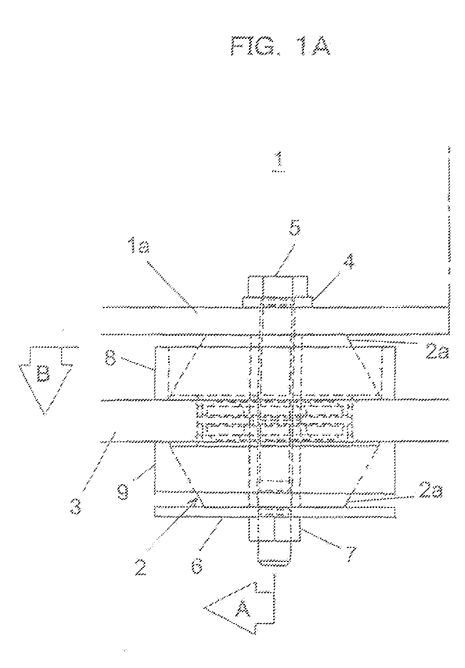
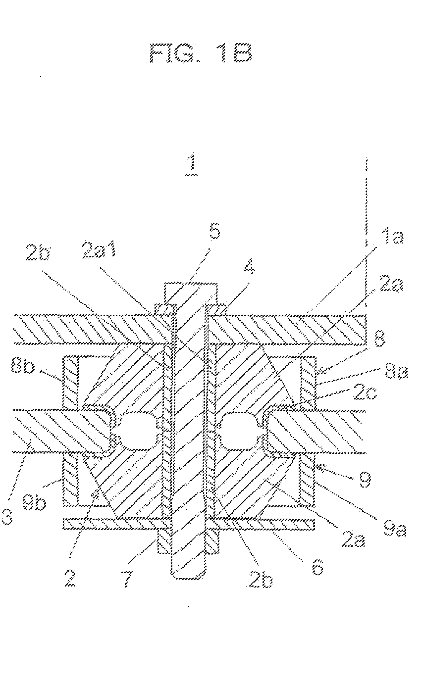
- FIGS. 1A to 1C are views illustrating a first embodiment of the vibration-damping support device according to the present invention, in which FIG. 1A is a front view, FIG. 1B is a cross-sectional view taken in the direction of arrow "A" of FIG. 1A, and FIG. 1C is a cross-sectional view taken in the direction of arrow "B" of FIG. 1A .
- the vibration-damping support device is useful upon mounting an engine 1 on a body (revolving) frame in a construction machine such as a hydraulic excavator, and as illustrated in FIGS. 1A and 1B , is provided with a mount, for example, a rubber mount 2, a support member supporting the rubber mount 2 thereon, for example, a support bracket 3, and stoppers 8, 9.
- the mount is to be attached to a mounting platform 1a for an object to be damped, for example, an engine 1, and has an elastic member for absorbing vibrations of the engine 1 in the up-and-down direction and in the horizontal direction.
- the elastic member is made of rubber or the like.
- the support bracket 3 is fixedly secured, for example, on the unillustrated revolving frame.
- the stoppers 8, 9 prevent an excessive deformation of the elastic member of the rubber mount 2 under vibrations of the engine 1.
- the elastic member of the rubber mount 2 is formed of a pair of truncated cones 2a arranged, for example, symmetrically about a horizontal plane.
- One of the paired truncated cones 2a, said one truncated cone 2a being located on an upper side, is arranged such that it is located close to the engine 1.
- the elastic member formed of the paired truncated cones 2a is supported at a vertically middle part thereof by the above-mentioned support bracket 3 via a flange 2c made, for example, of a metal.
- a pipe 2b made, for example, of a metal is inserted in an aperture 2a1 longitudinally extending through central parts of the paired truncated cones 2a.
- a bolt 5 for fixedly securing the rubber mount 2 on the mounting platform 1a for the engine 1 is inserted via a washer 4.
- a plate, for example, of a circular shape is secured, and this plate 6 is fastened by a nut 7 which is in threaded engagement with the bolt 5. Therefore, the paired truncated cones 2a that make up the elastic member of the rubber mount 2 are both supported by the support bracket 3 in a state that they are held between the mounting platform 1a for the engine 1 and the plate 6.
- the stoppers 8, 9 are both arranged integrally with the support bracket 3. These stoppers 8, 9 are each formed of plural plate members surrounding, for example, the elastic member of the rubber mount 2, specifically the paired truncated cones 2a.
- the stopper 8 fixedly secured on an upper side of the support bracket 3 is formed of two plate members 8a, 8b, which are, for example, formed in a circular arc shape as viewed in plan and arranged with spaces formed between them at their corresponding opposite end portions.
- the stopper 9 fixedly secured on a lower side of the support bracket 3 is also formed of two plate members 9a, 9b which are similar to the plate members 8a, 8b.
- the plate members 8a, 8b of the stopper 8 arranged on the upper side of the support bracket 3 are positioned close to the one of the paired truncated cone 2a, said one truncated cone 2a being arranged on the upper side, without leaving any substantial clearance between the plate members 8a, 8b and a large-diameter base portion of the one truncated cone 2a.
- the plate members 8a, 8b are arranged on the support bracket 3 such that a certain clearance is left open between the plate members 8a, 8b and the mounting platform 1a of the engine 1.
- the two plate members 9a, 9b of the stopper 9 arranged on the lower side of the support bracket 3 are positioned close to the other one of the paired truncated cone 2a, said other truncated cone 2a being arranged on the lower side, without leaving any substantial clearance between the plate members 9a, 9b and a large-diameter base portion of the other truncated cone 2a.
- the plate members 9a, 9b are arranged on the support bracket 3 such that a certain clearance is left open between the plate members 9a, 9b and the plate 6 fitted on the bolt 5.
- the engine 1 when the engine 1 is driven and vibrates in the vertical direction and horizontal direction, its vibrations are absorbed by elastic deformations of the paired truncated cones 1a of the rubber mount 2. Even when vertical vibrations of the engine 1 become large and the mounting platform 1a for the engine 1 comes into contact with the plate members 8a, 8b making up the stopper 8 on the upper side of the support bracket 3, the paired truncated cones 2a are prevented from any further, excessive deformation. As a consequence, the paired truncated cones 2a are protected from damage so that durability of the rubber mount 2 can be secured.
- the vibration-damping support device is held such that, when it is attached to the mounting platform 1a for the engine 1, the one of the paired truncated cones 2a, said one truncated cone 2a being positioned on the upper side, sags under the weight of the engine 1 itself.
- the clearance between the stopper 8 and the mounting platform 1a for the engine 1 is set beforehand smaller than that between the stopper 9 and the plate 6.
- the stopper 8 therefore becomes dominant. Described specifically, excessive deformations of the paired truncated cones 2a are prevented primarily by the contact of the upper stopper 8 with the mounting platform 1a for the engine 1.
- the vibration-damping support device is effective for the damping of the engine 1 in the hydraulic excavator. Even when the engine 1 is driven and vibrates, the plate members 8a, 8b, 9a, 9b, which make up the stoppers 8, 9, can be maintained stationary although the paired truncated cones 2a, 2b of the rubber mount 2 supported on the support bracket 3 deform under the vibrations of the engine, because the plate members 8a, 8b, 9a, 9b are arranged on the support bracket 3 fixedly secured on the revolving frame.
- the paired truncated cones 2a and the plate member members 8a, 8b, 9a, 9b, which make up the respective stoppers 8, 9, can be arranged without occurrence of an interference between them under vibrations of the engine 1 although substantially no clearance is left open between them.
- the outer diameter dimensions of the plate members 8a, 8b, 9a, 9b, which make up the respective stoppers 8, 9, can be reduced, thereby making it possible to reduce a space required for the installation of the vibration-damping support device itself according to the first embodiment.
- the vibration-damping support device according to the first embodiment can also be installed even in a machine that is prone to restrictions on an installation space for equipment, such as a hydraulic excavator of the small swing radius type.
- the stoppers 8, 9 are formed of the plate members 8a, 8b, 9a, 9b surrounding the paired truncated cones 2a of the rubber mount 2, and it is unnecessary to form the stoppers 8, 9 in a shallow cup shape.
- the stoppers 8, 9 can hence be manufactured by using a press machine of relatively small capacity.
- the stoppers 8, 9 may be manufactured in some instances by cutting work which is simpler than press work. The manufacture of these stopper 8, 9 can be facilitated whichever machining work is adopted. It is also possible to decrease the manufacturing man-hour of the vibration-damping support device according to the first embodiment.
- a desired stopper function specifically a function to prevent excessive deformations of the paired truncated cones 2a of the rubber mount 2 can be secured by the respective plate members 8a, 8b, 9a, 9b of the stoppers 8, 9 by setting beforehand the thickness dimension of each of the plate members 8a, 8b, 9a, 9b such that upon contact of the engine 1 with the plate members 8a, 8b, 9a, 9b, the contact areas of the plate members 8a, 8b, 9a, 9b become large enough to retain strength such that the paired truncated cones 2a are not damaged by the contact of the engine.
- the material cost can be saved upon manufacture of the stoppers 8, 9 by arranging the plate members, for example, the plate member 8a and the plate member 8b of the stopper 8 with spaces formed between them at their corresponding opposite end portions as illustrated in FIG. 1C .
- the plate members 8a, 8b, 9a, 9b of the stoppers 8, 9 are each formed in a circular arc shape, that is, a simple shape as viewed in plan. Therefore, the manufacture of these plate members 8a, 8b, 9a, 9b is easy, thereby contributing to a reduction in the manufacturing man-hour of the stoppers 8, 9.
- FIGS. 2A and 2B are views illustrating a second embodiment of the vibration-damping support device according to the present invention, in which FIG. 2A is a front view and FIG. 2B is a cross-sectional view taken in the direction of arrow "C" of FIG. 2A .
- the vibration-damping support device is constructed such that from the above-described vibration-damping support device according to the first embodiment, the stopper 9 arranged on the lower side of the support bracket 3 is eliminated and a washer 4a, the shape and dimensions of which are small, is fitted on the bolt 5 in place of the circular plate 6.
- the remaining construction is similar to the corresponding construction in the above-described vibration-damping support device according to the first embodiment.
- the stopper 9 is not arranged on the lower side of the support bracket 3 in this second embodiment. It is, therefore, impossible to prevent excessive deformations of the paired truncated cones 2a of the rubber mount 2 under occasional large vibrations of the engine 1.
- the material cost can, however, be cut down, because the second embodiment has the construction that it is not provided with the stopper 9 and is provided with the washer 4a the shape and dimensions of which are smaller compared with the plate 6.
- FIGS. 3A to 3C are views illustrating a third embodiment of the present invention, in which FIG. 3A is a front view, FIG. 3B is a cross-sectional view taken in the direction of arrow "D" of FIG. 3A, and FIG. 3C is a cross-sectional view taken in the direction of arrow "E" of FIG. 3A .
- the vibration-damping support device according to the third embodiment is provided with a stopper 10 on only the upper side of the support bracket 3.
- This stopper 10 is formed of two plate members 10a, 10b, which are each formed, for example, in a polygonally-bent shape as viewed in plan. These plate members 10a, 10b are arranged on the support bracket 3 and close to the rubber mount 2 such that the plate members 10a, 10b surround the rubber mount 12 and no substantial clearance is formed between the plate members 10a, 10b and the rubber mount 2.
- the plate members 10a, 10b, which make up the stopper 10 are also arranged such that openings 12 formed between the plate members 10a, 10b of the stopper 10 at corresponding end portions thereof face equipment 11 arranged around the vibration-damping support device according to the third embodiment.
- the remaining construction is similar to the corresponding construction in the above-described vibration-damping support device according to the second embodiment.
- the third embodiment can bring about similar advantageous effects as the second embodiment.
- the plate members 10a, 10b of the stopper 10 are each formed in the polygonally-bent shape, that is, a simple shape as viewed in plan. This shape can be realized by bending work, so that the manufacture of these plate members 10a, 10b is easy.
- the plate members 10a, 10b therefore, contribute to a reduction in the manufacturing man-hour of the stopper 10.
- the two plate members 10a, 10b, which make up the stopper 10 are arranged such that the openings 12 formed between the plate members 10a, 10b of the stopper 10 at the corresponding end portions thereof face the equipment 11 arranged around the vibration-damping support device according to the third embodiment.
- the equipment 11 can, therefore, be arranged sufficiently close to the vibration-damping support device according to the third embodiment. As a consequence, a large installation space can be secured for the equipment 11 to be arranged laterally to the vibration-damping support device according to the third embodiment.
- the stoppers 8, 9 are formed of the two plate members 8a, 8b and the two plate members 9a, 9b, respectively, in the first embodiment, the stopper 8 is formed of the two plate members 8a, 8b in the second embodiment, and the stopper 10 is formed of the two plate members 10a, 10b in the third embodiment.
- these stoppers 8, 9, 10 may each be formed of three or more plate members, or may each be formed of a plate member in the form of a cylindrical body having one or more seams.
- stoppers 8, 9, 10 may each be formed of a plate member in the form of a seamless cylindrical body.
- the stoppers formed of plate members in the form of such cylindrical bodies can be easily manufactured, for example, by simply subjecting a metal pipe to cutting work.
Landscapes
- Engineering & Computer Science (AREA)
- General Engineering & Computer Science (AREA)
- Mechanical Engineering (AREA)
- Vibration Prevention Devices (AREA)
- Arrangement Or Mounting Of Propulsion Units For Vehicles (AREA)
- Springs (AREA)
- Motor Or Generator Frames (AREA)
Abstract
Description
- This invention relates to a vibration-damping support device useful for the vibration-isolated support or the like of an engine in a construction machine.
- As a conventional technology of this sort, there is one disclosed in Patent Document 1.
FIGS. 4A and 4B are views illustrating a conventional technology substantially equal to the vibration-damping support device disclosed in Patent Document 1, in whichFIG. 4A is a front view andFIG. 4B is a cross-sectional view taken in the direction of arrow "F" ofFIG. 4A . - The conventional technology illustrated in
FIGS. 4A and 4B is directed to a vibration-damping engine support device to be installed on a machine such as a construction machine that is subjected to extreme vibrations in the vertical direction. This vibration-damping engine support device has a rubber mount 22, a support member supporting the rubber mount 22 thereon, specifically asupport bracket 23, and stoppers 28,29. The mount is attached to a mounting platform 21a for an object to be damped, specifically anengine 21, and has an elastic member 22a for absorbing vibrations of theengine 21 in the up-and-down direction and in the left-to-right direction, that is, the horizontal direction. Thestoppers engine 21, and are each formed in a shallow cup shape. - The
stopper 28 is arranged on an upper side of thesupport bracket 23, while thestopper 29 is arranged on a lower side of thesupport bracket 23. Thestopper 28 arranged on the upper side is integrally attached to the mounting platform 21a for theengine 21 via a bolt 25, and thestopper 29 arranged on the lower side is integrally attached to the bolt 25. The elastic member 22a of the rubber mount 22 is held between theupper stopper 28 and thelower stopper 29. - It is to be noted that the vibration-damping support device is held beforehand such that, when it is attached to the mounting platform 21a for the
engine 21, thestopper 28 and the elastic member 22a of the rubber mount 22 sag under the weight of theengine 21 itself. As a result, the clearance between thestopper 28 and thesupport bracket 23 becomes smaller than that between thestopper 29 and thesupport bracket 23. Consequently, the prevention of a deformation of the elastic member 22a under vibrations of theengine 21 in the vertical direction is achieved primarily by a contact of theupper stopper 28 to thesupport bracket 23. - Accordingto the conventional technology constructed as described above, when the
engine 21 is driven and vibrates in the vertical direction and horizontal direction, vibrations of theengine 21 are absorbed by deformations of the elastic member 22a of the rubber mount 22. Even when vibrations of theengine 21 in the vertical direction become large and theupper stopper 28 arranged integrally with theengine 21 comes into contact with an upper surface of thesupport bracket 23, the elastic member 22a is prevented from any further, excessive deformation. If vibrations of theengine 21 in the vertical direction become significantly large, for example, occasionally for any reason, thelower stopper 29 comes into contact with a lower surface of thesupport bracket 23. As a consequence, any excessive deformation of the elastic member 22a is prevented. - Any excessive deformation of the elastic member 22a of the rubber mount 22 under vibrations of the
engine 21 is prevented by thestoppers - Patent Document 1:
JP-A-9-177888 - In the conventional technology, the
stopper 28 is integrally attached to the mounting platform 21a for theengine 21, and thestopper 29 is integrally secured to the bolt 25 that attaches thestopper 28 to the mounting platform 21a for theengine 21, as mentioned above. Therefore, thestoppers engine 21 in the horizontal direction. To avoid an interference between thestoppers stoppers stoppers stoppers stoppers - Especially when a machine in which the conventional vibration-damping support device is to be installed is one that is prone to restrictions on an installation space for equipment, such as a hydraulic excavator of the small swing radius type, the above-mentioned conventional vibration-damping support device may be hardly installed in some instances.
- It is to be noted that in the above-mentioned conventional technology, the
stoppers stoppers stoppers shaped stoppers - With the foregoing circumstances of the above-mentioned conventional technology in view, the present invention has as an object thereof the provision of a vibration-damping support device that requires a smaller space for its own installation.
- To achieve the above-described object, a vibration-damping support device according to the present invention is characterized in that in the vibration-damping support device provided with a mount, which is to be attached to an object to be damped and has an elastic member for absorbing vibrations of the object to be damped, a support member supporting the mount thereon, and a stopper for preventing an excessive deformation of the elastic member in an up-and-down direction under the vibrations, the stopper is arranged integrally with the support member.
- In the present invention constructed as described above, when the object to be damped is driven and vibrates, its vibrations are absorbed by deformations of the elastic member of the mount. Even when vertical vibrations of the object to be damped become large and the object to be damped comes into contact with the stopper arranged integrally with the support member, any further deformation of the elastic member is prevented so that the elastic member is protected from damage. As a consequence, durability of the mount can be secured.
- Even when the object to be damped is driven and vibrates, the stopper can be maintained in a stationary state without moving under vibrations of the object to be damped although the elastic member of the mount supported on the support member deforms under the vibrations of the object to be damped, because the stopper is arranged integrally with the support member that can be maintained stationary. Further, the stopper is integrally arranged on the same support member as that supporting the elastic member of the mount. By making consideration about the shape and dimensions of the elastic member, the elastic member of the mount and the stopper can be arranged without occurrence of an interference between them under vibrations of the object to be damped although substantially no clearance is left open between them. As a consequence, the outer diameter dimension of the stopper can be reduced, thereby making it possible to reduce a space required for the installation of the vibration-damping support device itself according to the present invention.
- The vibration-damping support device according to the present invention may also be characterized in that in the above-described invention, the vibration-damping support device is to be installed in a construction machine, the object to be damped comprises an engine, and the stopper comprises a plate member surrounding the elastic member of the mount.
- The present invention constructed as described above is effective for the damping of the engine installed in the construction machine. Further, it is unnecessary to form the stopper in a shallow cup shape. Upon manufacturing the stopper by press work, it can hence be manufactured by using a press machine of relatively small capacity. Moreover, the stopper may be manufactured in some instances by cutting work which is simpler than press work. The manufacture of the stopper can be facilitated whichever machining work is adopted.
- The vibration-damping support device according to the present invention may also be characterized in that in the above-described invention, the stopper comprises a plurality of plate members.
- The present invention constructed as described above can secure a desired stopper function, specifically a deformation preventing function for the elastic member of the mount by the plate members by setting beforehand the thickness dimension of each of the plate members such that upon contact of the engine with the respective plate members, the contact areas of the plate members become large enough to retain strength such that the elastic member is not damaged by the contact of the engine. Moreover, the material cost can be saved upon manufacture of the stopper by arranging the plate members with spaces formed between the plate members at their corresponding opposite end portions.
- The vibration-damping support device according to the present invention may also be characterized in that in the above-described invention, the plate members are each formed in a circular arc shape as viewed in plan or a polygonally bent shape as viewed in plan. According to the present invention constructed as described above, the plate members are simple in shape, and therefore, can be manufactured easily.
- Further, the vibration-damping support device according to the present invention may also be characterized in that in the above-described invention, the elastic member of the mount comprises a pair of truncated cones arranged symmetrically about a horizontal plane, one of the paired truncated cone, said one truncated cone being located on an upper side, is to be arranged on a side closer to the engine, the support member comprises a support bracket for supporting thereon the elastic member at a vertically middle part thereof, and the plate member or one of the plate members is arranged on an upper side of the support bracket such that the plate member or the one plate member surrounds the one truncated cone located on the upper side.
- In the present invention constructed as described above, when the engine is driven and vibrates, its vibrations are absorbed by the paired truncated cones of the mount. Even when vertical vibrations of the engine become large and the engine comes into contact with the plate member making up the stopper on the upper side of the support bracket, any further deformation of one of the paired truncated cones, said one truncated cone being located on the upper side, is prevented so that the paired truncated cones are protected from damage. As a consequence, durability of the mount can be secured.
- Even when the engine is driven and vibrates, the plate member or plate members, which make up the stopper, can be maintained stationary although the paired truncated cones supported on the support bracket deform under the vibrations of the engine, because the plate member or plate members are arranged integrally with the support bracket that can be maintained stationary. Further, the paired truncated cones and the plate member or plate members can be arranged without occurrence of an interference between them under vibrations of the engine although substantially no clearance is left open between them. As a consequence, the outer diameter dimension or dimensions of the plate member or members making up the stopper can be reduced, thereby making it possible to reduce a space required for the installation of the vibration-damping support device itself according to the present invention.
- In the present invention, the stopper for preventing an excessive deformation of the elastic member in the up-and-down direction under vibrations of the object to be damped is integrally arranged on the mount having the elastic member that absorbs the vibrations of the object to be damped, and therefore, the stopper can be maintained stationary upon vibration of the object to be damped. Further, the mount is integrally arranged on the same support member as that supporting the elastic member of the mount. By making consideration about the shape and dimensions of the elastic member, the elastic member of the mount and the stopper can be arranged without occurrence of an interference between them under vibrations of the object to be damped although substantially no clearance is left open between them. As a consequence, the outer diameter dimension of the stopper can be reduced, thereby making it possible to reduce a space required for the installation of the vibration-damping support device itself according to the present invention. It is, therefore, possible to provide the layout design of equipment, which is to be installed around the vibration-damping support device according to the present invention, with a greater degree of freedom compared with that available in the conventional technology, and therefore, the vibration-damping support device according to the present invention can also be installed even in a machine that is prone to restrictions on an installation space for equipment, such as a hydraulic excavator of the small swing radius type.
- Best modes for carrying out the vibration-damping support device according to the present invention will hereinafter be described with reference to drawings.
-
FIGS. 1A to 1C are views illustrating a first embodiment of the vibration-damping support device according to the present invention, in whichFIG. 1A is a front view,FIG. 1B is a cross-sectional view taken in the direction of arrow "A" ofFIG. 1A, and FIG. 1C is a cross-sectional view taken in the direction of arrow "B" ofFIG. 1A . - The vibration-damping support device according to the first embodiment is useful upon mounting an engine 1 on a body (revolving) frame in a construction machine such as a hydraulic excavator, and as illustrated in
FIGS. 1A and 1B , is provided with a mount, for example, arubber mount 2, a support member supporting therubber mount 2 thereon, for example, asupport bracket 3, andstoppers 8, 9. The mount is to be attached to a mounting platform 1a for an object to be damped, for example, an engine 1, and has an elastic member for absorbing vibrations of the engine 1 in the up-and-down direction and in the horizontal direction. The elastic member is made of rubber or the like. Thesupport bracket 3 is fixedly secured, for example, on the unillustrated revolving frame. Thestoppers 8, 9 prevent an excessive deformation of the elastic member of therubber mount 2 under vibrations of the engine 1. - The elastic member of the
rubber mount 2 is formed of a pair of truncated cones 2a arranged, for example, symmetrically about a horizontal plane. One of the paired truncated cones 2a, said one truncated cone 2a being located on an upper side, is arranged such that it is located close to the engine 1. The elastic member formed of the paired truncated cones 2a is supported at a vertically middle part thereof by the above-mentionedsupport bracket 3 via a flange 2c made, for example, of a metal. - In an aperture 2a1 longitudinally extending through central parts of the paired truncated cones 2a, a
pipe 2b made, for example, of a metal is inserted. In themetal pipe 2b, abolt 5 for fixedly securing therubber mount 2 on the mounting platform 1a for the engine 1 is inserted via a washer 4. On and in engagement with a free end portion of thebolt 5, said free end portion being located on a side opposite to a head of thebolt 5, a plate, for example, of a circular shape is secured, and this plate 6 is fastened by anut 7 which is in threaded engagement with thebolt 5. Therefore, the paired truncated cones 2a that make up the elastic member of therubber mount 2 are both supported by thesupport bracket 3 in a state that they are held between the mounting platform 1a for the engine 1 and the plate 6. - The
stoppers 8, 9 are both arranged integrally with thesupport bracket 3. Thesestoppers 8, 9 are each formed of plural plate members surrounding, for example, the elastic member of therubber mount 2, specifically the paired truncated cones 2a. Thestopper 8 fixedly secured on an upper side of thesupport bracket 3 is formed of twoplate members 8a, 8b, which are, for example, formed in a circular arc shape as viewed in plan and arranged with spaces formed between them at their corresponding opposite end portions. The stopper 9 fixedly secured on a lower side of thesupport bracket 3 is also formed of two plate members 9a, 9b which are similar to theplate members 8a, 8b. - As illustrated in
FIGS. 1A to 1C , theplate members 8a, 8b of thestopper 8 arranged on the upper side of thesupport bracket 3 are positioned close to the one of the paired truncated cone 2a, said one truncated cone 2a being arranged on the upper side, without leaving any substantial clearance between theplate members 8a, 8b and a large-diameter base portion of the one truncated cone 2a. However, theplate members 8a, 8b are arranged on thesupport bracket 3 such that a certain clearance is left open between theplate members 8a, 8b and the mounting platform 1a of the engine 1. - Similarly, the two plate members 9a, 9b of the stopper 9 arranged on the lower side of the
support bracket 3 are positioned close to the other one of the paired truncated cone 2a, said other truncated cone 2a being arranged on the lower side, without leaving any substantial clearance between the plate members 9a, 9b and a large-diameter base portion of the other truncated cone 2a. However, the plate members 9a, 9b are arranged on thesupport bracket 3 such that a certain clearance is left open between the plate members 9a, 9b and the plate 6 fitted on thebolt 5. - According to the first embodiment constructed as described above, when the engine 1 is driven and vibrates in the vertical direction and horizontal direction, its vibrations are absorbed by elastic deformations of the paired truncated cones 1a of the
rubber mount 2. Even when vertical vibrations of the engine 1 become large and the mounting platform 1a for the engine 1 comes into contact with theplate members 8a, 8b making up thestopper 8 on the upper side of thesupport bracket 3, the paired truncated cones 2a are prevented from any further, excessive deformation. As a consequence, the paired truncated cones 2a are protected from damage so that durability of therubber mount 2 can be secured. - It is to be noted that the vibration-damping support device according to the first embodiment is held such that, when it is attached to the mounting platform 1a for the engine 1, the one of the paired truncated cones 2a, said one truncated cone 2a being positioned on the upper side, sags under the weight of the engine 1 itself. As a result, the clearance between the
stopper 8 and the mounting platform 1a for the engine 1 is set beforehand smaller than that between the stopper 9 and the plate 6. Concerning the prevention of excessive deformations of the paired truncated cones 2a under vibrations of the engine 1 in the vertical direction, thestopper 8 therefore becomes dominant. Described specifically, excessive deformations of the paired truncated cones 2a are prevented primarily by the contact of theupper stopper 8 with the mounting platform 1a for the engine 1. - If vibrations of the engine 1 in the vertical direction become significantly large, for example, occasionally and the plate 6 fitted on the
bolt 5 comes into contact with the stopper 9 arranged on the lower side of thesupport bracket 3, any excessive deformations of the paired truncated cones 2a are prevented. - The vibration-damping support device according to the first embodiment is effective for the damping of the engine 1 in the hydraulic excavator. Even when the engine 1 is driven and vibrates, the
plate members 8a, 8b, 9a, 9b, which make up thestoppers 8, 9, can be maintained stationary although the pairedtruncated cones 2a, 2b of therubber mount 2 supported on thesupport bracket 3 deform under the vibrations of the engine, because theplate members 8a, 8b, 9a, 9b are arranged on thesupport bracket 3 fixedly secured on the revolving frame. As mentioned above, the paired truncated cones 2a and theplate member members 8a, 8b, 9a, 9b, which make up therespective stoppers 8, 9, can be arranged without occurrence of an interference between them under vibrations of the engine 1 although substantially no clearance is left open between them. As a consequence, the outer diameter dimensions of theplate members 8a, 8b, 9a, 9b, which make up therespective stoppers 8, 9, can be reduced, thereby making it possible to reduce a space required for the installation of the vibration-damping support device itself according to the first embodiment. It is, therefore, possible to provide the layout design of equipment, which is to be installed around the vibration-damping support device according to the first embodiment, with a greater degree of freedom, and therefore, the vibration-damping support device according to the first embodiment can also be installed even in a machine that is prone to restrictions on an installation space for equipment, such as a hydraulic excavator of the small swing radius type. - The
stoppers 8, 9 are formed of theplate members 8a, 8b, 9a, 9b surrounding the paired truncated cones 2a of therubber mount 2, and it is unnecessary to form thestoppers 8, 9 in a shallow cup shape. Upon manufacturing thestoppers 8, 9 by press work, they can hence be manufactured by using a press machine of relatively small capacity. Moreover, thestoppers 8, 9 may be manufactured in some instances by cutting work which is simpler than press work. The manufacture of thesestopper 8, 9 can be facilitated whichever machining work is adopted. It is also possible to decrease the manufacturing man-hour of the vibration-damping support device according to the first embodiment. - A desired stopper function, specifically a function to prevent excessive deformations of the paired truncated cones 2a of the
rubber mount 2 can be secured by therespective plate members 8a, 8b, 9a, 9b of thestoppers 8, 9 by setting beforehand the thickness dimension of each of theplate members 8a, 8b, 9a, 9b such that upon contact of the engine 1 with theplate members 8a, 8b, 9a, 9b, the contact areas of theplate members 8a, 8b, 9a, 9b become large enough to retain strength such that the paired truncated cones 2a are not damaged by the contact of the engine. Moreover, the material cost can be saved upon manufacture of thestoppers 8, 9 by arranging the plate members, for example, the plate member 8a and theplate member 8b of thestopper 8 with spaces formed between them at their corresponding opposite end portions as illustrated inFIG. 1C . - Further, the
plate members 8a, 8b, 9a, 9b of thestoppers 8, 9 are each formed in a circular arc shape, that is, a simple shape as viewed in plan. Therefore, the manufacture of theseplate members 8a, 8b, 9a, 9b is easy, thereby contributing to a reduction in the manufacturing man-hour of thestoppers 8, 9. -
FIGS. 2A and 2B are views illustrating a second embodiment of the vibration-damping support device according to the present invention, in whichFIG. 2A is a front view andFIG. 2B is a cross-sectional view taken in the direction of arrow "C" ofFIG. 2A . - The vibration-damping support device according to this second embodiment is constructed such that from the above-described vibration-damping support device according to the first embodiment, the stopper 9 arranged on the lower side of the
support bracket 3 is eliminated and a washer 4a, the shape and dimensions of which are small, is fitted on thebolt 5 in place of the circular plate 6. The remaining construction is similar to the corresponding construction in the above-described vibration-damping support device according to the first embodiment. - Normal vibrations of the engine 1, which are produced by drive of the engine 1, are absorbed primarily by the one of the truncated cones 2a of the
rubber mount 2, said one truncated cone 2a being arranged on the upper side of thesupport bracket 3, as mentioned above with respect to the first embodiment. In the second embodiment illustrated inFIGS. 2A and 2B , vibrations of the engine 1 can, therefore, be absorbed as in the first embodiment. As thestopper 8 formed of the twoplate members 8a, 8b is arranged on thesupport bracket 3, the second embodiment can bring about similar advantageous effects as the first embodiment. - Different from the first embodiment, the stopper 9 is not arranged on the lower side of the
support bracket 3 in this second embodiment. It is, therefore, impossible to prevent excessive deformations of the paired truncated cones 2a of therubber mount 2 under occasional large vibrations of the engine 1. The material cost can, however, be cut down, because the second embodiment has the construction that it is not provided with the stopper 9 and is provided with the washer 4a the shape and dimensions of which are smaller compared with the plate 6. In addition, it is possible to secure a large installation space for equipment to be arranged around the other truncated cone 2a on the lower side of thesupport bracket 3. -
FIGS. 3A to 3C are views illustrating a third embodiment of the present invention, in whichFIG. 3A is a front view,FIG. 3B is a cross-sectional view taken in the direction of arrow "D" ofFIG. 3A, and FIG. 3C is a cross-sectional view taken in the direction of arrow "E" ofFIG. 3A . - Similar to the above-described vibration-damping support device according to the second embodiment, the vibration-damping support device according to the third embodiment is provided with a
stopper 10 on only the upper side of thesupport bracket 3. Thisstopper 10 is formed of twoplate members 10a, 10b, which are each formed, for example, in a polygonally-bent shape as viewed in plan. Theseplate members 10a, 10b are arranged on thesupport bracket 3 and close to therubber mount 2 such that theplate members 10a, 10b surround therubber mount 12 and no substantial clearance is formed between theplate members 10a, 10b and therubber mount 2. Further, theplate members 10a, 10b, which make up thestopper 10, are also arranged such thatopenings 12 formed between theplate members 10a, 10b of thestopper 10 at corresponding end portions thereof face equipment 11 arranged around the vibration-damping support device according to the third embodiment. The remaining construction is similar to the corresponding construction in the above-described vibration-damping support device according to the second embodiment. - As the
stopper 10 formed of the twoplate members 10a, 10b is also arranged on only the upper side of thesupport bracket 3 in the third embodiment constructed as described above, the third embodiment can bring about similar advantageous effects as the second embodiment. Further, theplate members 10a, 10b of thestopper 10 are each formed in the polygonally-bent shape, that is, a simple shape as viewed in plan. This shape can be realized by bending work, so that the manufacture of theseplate members 10a, 10b is easy. Theplate members 10a, 10b, therefore, contribute to a reduction in the manufacturing man-hour of thestopper 10. - Further, the two
plate members 10a, 10b, which make up thestopper 10, are arranged such that theopenings 12 formed between theplate members 10a, 10b of thestopper 10 at the corresponding end portions thereof face the equipment 11 arranged around the vibration-damping support device according to the third embodiment. The equipment 11 can, therefore, be arranged sufficiently close to the vibration-damping support device according to the third embodiment. As a consequence, a large installation space can be secured for the equipment 11 to be arranged laterally to the vibration-damping support device according to the third embodiment. - The
stoppers 8, 9 are formed of the twoplate members 8a, 8b and the two plate members 9a, 9b, respectively, in the first embodiment, thestopper 8 is formed of the twoplate members 8a, 8b in the second embodiment, and thestopper 10 is formed of the twoplate members 10a, 10b in the third embodiment. However, thesestoppers - Further, the
stoppers -
- [
FIGS. 1A to 1C] FIGS. 1A to 1C are views illustrating a first embodiment of the vibration-damping support device according to the present invention, in whichFIG. 1A is a front view,FIG. 1B is a cross-sectional view taken in the direction of arrow "A" ofFIG. 1A, and FIG. 1C is a cross-sectional view taken in the direction of arrow "B" ofFIG. 1A . - [
FIGS. 2A and 2B] FIGS. 2A and 2B are views illustrating a second embodiment of the vibration-damping support device according to the present invention, in whichFIG. 2A is a front view andFIG. 2B is a cross-sectional view taken in the direction of arrow "C" ofFIG. 2A . - [
FIGS. 3A to 3C] FIGS. 3A to 3C are views illustrating a third embodiment of the present invention, in whichFIG. 3A is a front view,FIG. 3B is a cross-sectional view taken in the direction of arrow "D" ofFIG. 3A, and FIG. 3C is a cross-sectional view taken in the direction of arrow "E" ofFIG. 3A . - [
FIGS. 4A and 4B] FIGS. 4A and 4B are views illustrating a conventional technology substantially equal to the vibration-damping support device disclosed in Patent Document 1, in whichFIG. 4A is a front view andFIG. 4B is a cross-sectional view taken in the direction of arrow "F" ofFIG. 4A . -
- 1
- Engine (object to be damped)
- 1a
- Mounting platform
- 2
- Rubber mount (mount)
- 2a
- Truncated cone (elastic member)
- 2a1
- Aperture
- 2b
- Metal pipe
- 2c
- Flange
- 3
- Support bracket (support member)
- 4
- Washer
- 4a
- Washer
- 5
- Bolt
- 6
- Plate
- 7
- Nut
- 8
- Stopper
- 8a
- Plate member
- 8b
- Plate member
- 9
- Stopper
- 10
- Stopper
- 10a
- Plate member
- 10b
- Plate member
- 11
- Equipment
- 12
- Opening
Claims (5)
- A vibration-damping support device provided with a mount, which is to be attached to an object to be damped and has an elastic member for absorbing vibrations of the object to be damped, a support member supporting the mount thereon, and a stopper for preventing an excessive deformation of the elastic member in an up-and-down direction under the vibrations, wherein:the stopper is arranged integrally with the support member.
- The vibration-damping support device according to claim 1, wherein:the vibration-damping support device is to be installed in a construction machine, and the object to be damped comprises an engine, andthe stopper comprises a plate member surrounding the elastic member of the mount.
- The vibration-damping support device according to claim 2, wherein:the stopper comprises a plurality of plate members.
- The vibration-damping support device according to claim 3, wherein:the plate members are each formed in a circular arc shape as viewed in plan or a polygonally bent shape as viewed in plan.
- The vibration-damping support device according to any one of claims 2 to 4, wherein:the elastic member of the mount comprises a pair of truncated cones arranged symmetrically about a horizontal plane,one of the paired truncated cone, said one truncated cone being located on an upper side, is to be arranged on a side closer to the engine,the support member comprises a support bracket for supporting thereon the elastic member at a vertically middle part thereof, andthe plate member or one of the plate members is arranged on an upper side of the support bracket such that the plate member or the one plate member surrounds the one truncated cone located on the upper side.
Applications Claiming Priority (2)
| Application Number | Priority Date | Filing Date | Title |
|---|---|---|---|
| JP2008040255A JP5355901B2 (en) | 2008-02-21 | 2008-02-21 | Anti-vibration support device |
| PCT/JP2009/053072 WO2009104754A1 (en) | 2008-02-21 | 2009-02-20 | Vibration-damping support device |
Publications (3)
| Publication Number | Publication Date |
|---|---|
| EP2253864A1 true EP2253864A1 (en) | 2010-11-24 |
| EP2253864A4 EP2253864A4 (en) | 2012-12-26 |
| EP2253864B1 EP2253864B1 (en) | 2014-03-26 |
Family
ID=40985631
Family Applications (1)
| Application Number | Title | Priority Date | Filing Date |
|---|---|---|---|
| EP09712020.8A Active EP2253864B1 (en) | 2008-02-21 | 2009-02-20 | Vibration-damping support device |
Country Status (5)
| Country | Link |
|---|---|
| US (1) | US8950738B2 (en) |
| EP (1) | EP2253864B1 (en) |
| JP (1) | JP5355901B2 (en) |
| CN (1) | CN101952616B (en) |
| WO (1) | WO2009104754A1 (en) |
Families Citing this family (28)
| Publication number | Priority date | Publication date | Assignee | Title |
|---|---|---|---|---|
| US9010716B2 (en) * | 2010-02-04 | 2015-04-21 | Bridgestone Corporation | Vibration-damping device |
| JP5525396B2 (en) * | 2010-09-10 | 2014-06-18 | 倉敷化工株式会社 | Vibration isolator |
| RU2506474C2 (en) * | 2012-01-11 | 2014-02-10 | Федеральное государственное бюджетное образовательное учреждение высшего профессионального образования "Самарский государственный аэрокосмический университет имени академика С.П. Королева" (национальный исследовательский университет)" (СГАУ) | Vibration isolator of large carrying capacity |
| RU2496034C2 (en) * | 2012-01-23 | 2013-10-20 | Федеральное государственное бюджетное образовательное учреждение высшего профессионального образования "Самарский государственный аэрокосмический университет имени академика С.П. Королева" (национальный исследовательский университет)" (СГАУ) | Cassette low-frequency vibration isolator of high load capacity (clvihl) |
| RU2506475C2 (en) * | 2012-01-23 | 2014-02-10 | Федеральное государственное бюджетное образовательное учреждение высшего профессионального образования "Самарский государственный аэрокосмический университет имени академика С.П. Королева" (национальный исследовательский университет)" (СГАУ) | Unloaded vibration isolator of large carrying capacity |
| RU2506473C1 (en) * | 2012-06-06 | 2014-02-10 | Федеральное государственное бюджетное образовательное учреждение высшего профессионального образования "Самарский государственный аэрокосмический университет имени академика С.П. Королева" (национальный исследовательский университет)" (СГАУ) | Unloaded low-frequency vibration isolator of large carrying capacity |
| CN103303118A (en) * | 2013-06-19 | 2013-09-18 | 徐州徐工挖掘机械有限公司 | Engine suspension system for hydraulic excavator |
| JP6190651B2 (en) | 2013-07-23 | 2017-08-30 | 住友理工株式会社 | Vibration isolator |
| KR101601441B1 (en) * | 2014-06-27 | 2016-03-09 | 현대자동차주식회사 | Sub frame mounting bush |
| EP3173656B1 (en) * | 2014-07-22 | 2019-09-25 | Wel Research Co., Ltd. | Shock absorbing device |
| CN104728339B (en) * | 2015-04-13 | 2017-04-12 | 核工业理化工程研究院 | Rotating device energy absorption protection device |
| CN105041933A (en) * | 2015-06-15 | 2015-11-11 | 株洲时代新材料科技股份有限公司 | Two-way vibration reduction elastomer |
| CN105150823B (en) * | 2015-10-21 | 2017-12-22 | 安徽江淮汽车集团股份有限公司 | Engine mounting and automobile |
| BE1024071B1 (en) * | 2015-11-03 | 2017-11-10 | Cdm Nv | ELASTIC SUPPORT WITH OPTIL SAFETY AND METHOD FOR DISCONNECTING CORE CORDS AND WALLS OF BUILDINGS |
| RU2638363C1 (en) * | 2016-09-19 | 2017-12-13 | Олег Савельевич Кочетов | Vibration isolator of large carrying capacity |
| US10655664B2 (en) * | 2016-10-04 | 2020-05-19 | Illinois Tool Works Inc. | Fastener assembly having one or more grommets |
| CN106678272A (en) * | 2016-12-28 | 2017-05-17 | 中国航空工业集团公司西安飞机设计研究所 | Damping device with height limited space |
| CN108571562A (en) * | 2018-06-26 | 2018-09-25 | 贵州航天控制技术有限公司 | A kind of integrated vibration absorber of vehicle-mounted inertial navigation system |
| DE102019005092B4 (en) * | 2019-07-22 | 2022-05-12 | Sumitomo Riko Company Limited | Vibration damper and method for manufacturing a vibration damper |
| RU2745594C2 (en) * | 2019-09-13 | 2021-03-29 | Федеральное государственное бюджетное образовательное учреждение высшего образования "Самарский государственный университет путей сообщения" (СамГУПС) | Method for manufacturing empty vibration insulator |
| KR102305311B1 (en) * | 2020-02-24 | 2021-09-24 | 엘에스일렉트릭(주) | Vibration proofing device |
| DE102020128549A1 (en) * | 2020-10-29 | 2022-05-05 | Böllhoff Verbindungstechnik GmbH | Damping arrangement, component with damping arrangement and corresponding component connection, a manufacturing method and a connection method |
| CN112594328A (en) * | 2020-12-25 | 2021-04-02 | 天津瑞能电气有限公司 | Vibration reduction mounting device of electric control cabinet |
| JP7622494B2 (en) | 2021-03-23 | 2025-01-28 | 株式会社豊田自動織機 | Automotive Electric Fluid Machinery |
| DE102022105703A1 (en) * | 2022-03-10 | 2023-09-14 | Vibracoustic Se | Storage arrangement |
| DE102022110271A1 (en) * | 2022-04-27 | 2023-11-02 | Böllhoff Verbindungstechnik GmbH | Damping arrangement, component with damping arrangement, corresponding component connection, connection method and manufacturing method |
| JP2024084467A (en) * | 2022-12-13 | 2024-06-25 | 株式会社タダノ | Work vehicle mount and work vehicle |
| CN118188755B (en) * | 2024-05-17 | 2024-07-12 | 上海海事大学 | Vibration reduction structure of ship tail gas treatment device and installation method |
Family Cites Families (15)
| Publication number | Priority date | Publication date | Assignee | Title |
|---|---|---|---|---|
| US3430901A (en) * | 1967-07-20 | 1969-03-04 | Andre Cauvin | Mounting device for the engine block of a vehicle |
| JPS5428815U (en) * | 1977-07-29 | 1979-02-24 | ||
| US4168207A (en) | 1977-08-03 | 1979-09-18 | Syva Company | TBG assay |
| JPS5538055U (en) * | 1978-09-04 | 1980-03-11 | ||
| JPS60139936U (en) * | 1984-02-29 | 1985-09-17 | 三菱自動車工業株式会社 | rubber butt |
| US5242146A (en) * | 1988-11-14 | 1993-09-07 | Navistar International Transportation Corp. | Engine mount having improved vibration isolation |
| DE3919775C2 (en) * | 1989-06-16 | 1994-09-01 | Daimler Benz Ag | Support bearing |
| JPH0479780A (en) | 1990-07-18 | 1992-03-13 | Toshiba Corp | Magnetostriction type actuator |
| JP2557909Y2 (en) * | 1990-11-27 | 1997-12-17 | 本田技研工業株式会社 | Seat fixing structure for vehicles such as motorcycles |
| JP2880349B2 (en) * | 1992-05-27 | 1999-04-05 | 住友建機株式会社 | Engine mounting device |
| US5456454A (en) * | 1993-06-15 | 1995-10-10 | Mercedes-Benz Ag | Support bearing for automotive vehicles |
| JPH09177888A (en) * | 1995-12-27 | 1997-07-11 | Hitachi Constr Mach Co Ltd | Engine anti-vibration support device |
| US5842677A (en) * | 1996-09-26 | 1998-12-01 | Lord Corporation | Safetied sandwich mount assembly with integral holding and centering feature |
| DE29710578U1 (en) * | 1997-06-17 | 1997-08-28 | Woco Franz-Josef Wolf & Co, 63628 Bad Soden-Salmünster | Tie-in bearing |
| US7735812B2 (en) * | 2003-04-30 | 2010-06-15 | Trelleborg Ab | Vibration-damping device |
-
2008
- 2008-02-21 JP JP2008040255A patent/JP5355901B2/en active Active
-
2009
- 2009-02-20 US US12/918,654 patent/US8950738B2/en active Active
- 2009-02-20 CN CN2009801058488A patent/CN101952616B/en active Active
- 2009-02-20 WO PCT/JP2009/053072 patent/WO2009104754A1/en not_active Ceased
- 2009-02-20 EP EP09712020.8A patent/EP2253864B1/en active Active
Also Published As
| Publication number | Publication date |
|---|---|
| US20100327502A1 (en) | 2010-12-30 |
| WO2009104754A1 (en) | 2009-08-27 |
| JP5355901B2 (en) | 2013-11-27 |
| EP2253864A4 (en) | 2012-12-26 |
| JP2009197910A (en) | 2009-09-03 |
| US8950738B2 (en) | 2015-02-10 |
| CN101952616A (en) | 2011-01-19 |
| EP2253864B1 (en) | 2014-03-26 |
| CN101952616B (en) | 2013-03-13 |
Similar Documents
| Publication | Publication Date | Title |
|---|---|---|
| EP2253864B1 (en) | Vibration-damping support device | |
| EP2662591B1 (en) | Anti-vibration device | |
| JP2009530525A (en) | Apparatus and method for installing fluid rotating machine | |
| CN111843984A (en) | Horizontal multi-joint robot | |
| JP2015168936A (en) | Cab protective structure in work machine | |
| JP3608139B2 (en) | Anti-vibration bearing structure | |
| KR20170094822A (en) | Below bridge support having variable anchor socket | |
| KR102813122B1 (en) | Vertical mill device equipped with anti-vibration means | |
| US9956862B2 (en) | Engine unit support structure and engine unit mounting method | |
| JP4117814B2 (en) | Trigger mechanism of seismic isolation device | |
| JP2020011374A (en) | Horizontal articulated robot | |
| JP2006214187A (en) | Seismic isolation device | |
| CN216428396U (en) | Anti-axial-movement damping mechanism and excavator | |
| JP3034534U (en) | Load detector | |
| CN222513682U (en) | Bowl-shaped rubber shock absorber | |
| JP2007176401A (en) | Vibration-isolating mount fixing tool | |
| US20240399845A1 (en) | Fastening structure for vehicular mounting system | |
| CN208348373U (en) | Damping device and bikini support system for bikini support system | |
| JP2005282663A (en) | Vibration absorbing mount | |
| JP2010184763A (en) | Aseismatic structure of hoisting machine | |
| KR20220040615A (en) | Fastening apparatus for cylinderic structure | |
| JP3963804B2 (en) | Anchor member | |
| KR200229655Y1 (en) | Antivibration Rubber Assembly Protection Device for Elevator Floor | |
| JP4990220B2 (en) | Seismic isolation device | |
| JP4174456B2 (en) | Sliding bearing |
Legal Events
| Date | Code | Title | Description |
|---|---|---|---|
| PUAI | Public reference made under article 153(3) epc to a published international application that has entered the european phase |
Free format text: ORIGINAL CODE: 0009012 |
|
| 17P | Request for examination filed |
Effective date: 20100913 |
|
| AK | Designated contracting states |
Kind code of ref document: A1 Designated state(s): AT BE BG CH CY CZ DE DK EE ES FI FR GB GR HR HU IE IS IT LI LT LU LV MC MK MT NL NO PL PT RO SE SI SK TR |
|
| AX | Request for extension of the european patent |
Extension state: AL BA RS |
|
| DAX | Request for extension of the european patent (deleted) | ||
| A4 | Supplementary search report drawn up and despatched |
Effective date: 20121122 |
|
| RIC1 | Information provided on ipc code assigned before grant |
Ipc: F16F 1/373 20060101ALI20121116BHEP Ipc: F16F 1/38 20060101ALI20121116BHEP Ipc: F16F 1/36 20060101ALI20121116BHEP Ipc: F16F 15/08 20060101AFI20121116BHEP Ipc: B60K 5/12 20060101ALI20121116BHEP |
|
| GRAP | Despatch of communication of intention to grant a patent |
Free format text: ORIGINAL CODE: EPIDOSNIGR1 |
|
| INTG | Intention to grant announced |
Effective date: 20131018 |
|
| GRAS | Grant fee paid |
Free format text: ORIGINAL CODE: EPIDOSNIGR3 |
|
| GRAA | (expected) grant |
Free format text: ORIGINAL CODE: 0009210 |
|
| AK | Designated contracting states |
Kind code of ref document: B1 Designated state(s): AT BE BG CH CY CZ DE DK EE ES FI FR GB GR HR HU IE IS IT LI LT LU LV MC MK MT NL NO PL PT RO SE SI SK TR |
|
| REG | Reference to a national code |
Ref country code: GB Ref legal event code: FG4D |
|
| REG | Reference to a national code |
Ref country code: CH Ref legal event code: EP |
|
| REG | Reference to a national code |
Ref country code: AT Ref legal event code: REF Ref document number: 659165 Country of ref document: AT Kind code of ref document: T Effective date: 20140415 |
|
| REG | Reference to a national code |
Ref country code: IE Ref legal event code: FG4D |
|
| REG | Reference to a national code |
Ref country code: DE Ref legal event code: R096 Ref document number: 602009022750 Country of ref document: DE Effective date: 20140508 |
|
| PG25 | Lapsed in a contracting state [announced via postgrant information from national office to epo] |
Ref country code: LT Free format text: LAPSE BECAUSE OF FAILURE TO SUBMIT A TRANSLATION OF THE DESCRIPTION OR TO PAY THE FEE WITHIN THE PRESCRIBED TIME-LIMIT Effective date: 20140326 Ref country code: NO Free format text: LAPSE BECAUSE OF FAILURE TO SUBMIT A TRANSLATION OF THE DESCRIPTION OR TO PAY THE FEE WITHIN THE PRESCRIBED TIME-LIMIT Effective date: 20140626 |
|
| REG | Reference to a national code |
Ref country code: AT Ref legal event code: MK05 Ref document number: 659165 Country of ref document: AT Kind code of ref document: T Effective date: 20140326 |
|
| REG | Reference to a national code |
Ref country code: NL Ref legal event code: VDEP Effective date: 20140326 |
|
| REG | Reference to a national code |
Ref country code: LT Ref legal event code: MG4D |
|
| PG25 | Lapsed in a contracting state [announced via postgrant information from national office to epo] |
Ref country code: FI Free format text: LAPSE BECAUSE OF FAILURE TO SUBMIT A TRANSLATION OF THE DESCRIPTION OR TO PAY THE FEE WITHIN THE PRESCRIBED TIME-LIMIT Effective date: 20140326 Ref country code: SE Free format text: LAPSE BECAUSE OF FAILURE TO SUBMIT A TRANSLATION OF THE DESCRIPTION OR TO PAY THE FEE WITHIN THE PRESCRIBED TIME-LIMIT Effective date: 20140326 |
|
| PG25 | Lapsed in a contracting state [announced via postgrant information from national office to epo] |
Ref country code: HR Free format text: LAPSE BECAUSE OF FAILURE TO SUBMIT A TRANSLATION OF THE DESCRIPTION OR TO PAY THE FEE WITHIN THE PRESCRIBED TIME-LIMIT Effective date: 20140326 Ref country code: LV Free format text: LAPSE BECAUSE OF FAILURE TO SUBMIT A TRANSLATION OF THE DESCRIPTION OR TO PAY THE FEE WITHIN THE PRESCRIBED TIME-LIMIT Effective date: 20140326 |
|
| PG25 | Lapsed in a contracting state [announced via postgrant information from national office to epo] |
Ref country code: RO Free format text: LAPSE BECAUSE OF FAILURE TO SUBMIT A TRANSLATION OF THE DESCRIPTION OR TO PAY THE FEE WITHIN THE PRESCRIBED TIME-LIMIT Effective date: 20140326 Ref country code: NL Free format text: LAPSE BECAUSE OF FAILURE TO SUBMIT A TRANSLATION OF THE DESCRIPTION OR TO PAY THE FEE WITHIN THE PRESCRIBED TIME-LIMIT Effective date: 20140326 Ref country code: CZ Free format text: LAPSE BECAUSE OF FAILURE TO SUBMIT A TRANSLATION OF THE DESCRIPTION OR TO PAY THE FEE WITHIN THE PRESCRIBED TIME-LIMIT Effective date: 20140326 Ref country code: BG Free format text: LAPSE BECAUSE OF FAILURE TO SUBMIT A TRANSLATION OF THE DESCRIPTION OR TO PAY THE FEE WITHIN THE PRESCRIBED TIME-LIMIT Effective date: 20140626 Ref country code: EE Free format text: LAPSE BECAUSE OF FAILURE TO SUBMIT A TRANSLATION OF THE DESCRIPTION OR TO PAY THE FEE WITHIN THE PRESCRIBED TIME-LIMIT Effective date: 20140326 Ref country code: CY Free format text: LAPSE BECAUSE OF FAILURE TO SUBMIT A TRANSLATION OF THE DESCRIPTION OR TO PAY THE FEE WITHIN THE PRESCRIBED TIME-LIMIT Effective date: 20140326 Ref country code: BE Free format text: LAPSE BECAUSE OF FAILURE TO SUBMIT A TRANSLATION OF THE DESCRIPTION OR TO PAY THE FEE WITHIN THE PRESCRIBED TIME-LIMIT Effective date: 20140326 Ref country code: IS Free format text: LAPSE BECAUSE OF FAILURE TO SUBMIT A TRANSLATION OF THE DESCRIPTION OR TO PAY THE FEE WITHIN THE PRESCRIBED TIME-LIMIT Effective date: 20140726 |
|
| PG25 | Lapsed in a contracting state [announced via postgrant information from national office to epo] |
Ref country code: AT Free format text: LAPSE BECAUSE OF FAILURE TO SUBMIT A TRANSLATION OF THE DESCRIPTION OR TO PAY THE FEE WITHIN THE PRESCRIBED TIME-LIMIT Effective date: 20140326 Ref country code: SK Free format text: LAPSE BECAUSE OF FAILURE TO SUBMIT A TRANSLATION OF THE DESCRIPTION OR TO PAY THE FEE WITHIN THE PRESCRIBED TIME-LIMIT Effective date: 20140326 Ref country code: ES Free format text: LAPSE BECAUSE OF FAILURE TO SUBMIT A TRANSLATION OF THE DESCRIPTION OR TO PAY THE FEE WITHIN THE PRESCRIBED TIME-LIMIT Effective date: 20140326 Ref country code: PL Free format text: LAPSE BECAUSE OF FAILURE TO SUBMIT A TRANSLATION OF THE DESCRIPTION OR TO PAY THE FEE WITHIN THE PRESCRIBED TIME-LIMIT Effective date: 20140326 |
|
| PG25 | Lapsed in a contracting state [announced via postgrant information from national office to epo] |
Ref country code: PT Free format text: LAPSE BECAUSE OF FAILURE TO SUBMIT A TRANSLATION OF THE DESCRIPTION OR TO PAY THE FEE WITHIN THE PRESCRIBED TIME-LIMIT Effective date: 20140728 |
|
| REG | Reference to a national code |
Ref country code: DE Ref legal event code: R097 Ref document number: 602009022750 Country of ref document: DE |
|
| PG25 | Lapsed in a contracting state [announced via postgrant information from national office to epo] |
Ref country code: DK Free format text: LAPSE BECAUSE OF FAILURE TO SUBMIT A TRANSLATION OF THE DESCRIPTION OR TO PAY THE FEE WITHIN THE PRESCRIBED TIME-LIMIT Effective date: 20140326 |
|
| PLBE | No opposition filed within time limit |
Free format text: ORIGINAL CODE: 0009261 |
|
| STAA | Information on the status of an ep patent application or granted ep patent |
Free format text: STATUS: NO OPPOSITION FILED WITHIN TIME LIMIT |
|
| 26N | No opposition filed |
Effective date: 20150106 |
|
| REG | Reference to a national code |
Ref country code: DE Ref legal event code: R097 Ref document number: 602009022750 Country of ref document: DE Effective date: 20150106 |
|
| PG25 | Lapsed in a contracting state [announced via postgrant information from national office to epo] |
Ref country code: SI Free format text: LAPSE BECAUSE OF FAILURE TO SUBMIT A TRANSLATION OF THE DESCRIPTION OR TO PAY THE FEE WITHIN THE PRESCRIBED TIME-LIMIT Effective date: 20140326 |
|
| PG25 | Lapsed in a contracting state [announced via postgrant information from national office to epo] |
Ref country code: LU Free format text: LAPSE BECAUSE OF FAILURE TO SUBMIT A TRANSLATION OF THE DESCRIPTION OR TO PAY THE FEE WITHIN THE PRESCRIBED TIME-LIMIT Effective date: 20150220 |
|
| REG | Reference to a national code |
Ref country code: CH Ref legal event code: PL |
|
| GBPC | Gb: european patent ceased through non-payment of renewal fee |
Effective date: 20150220 |
|
| PG25 | Lapsed in a contracting state [announced via postgrant information from national office to epo] |
Ref country code: CH Free format text: LAPSE BECAUSE OF NON-PAYMENT OF DUE FEES Effective date: 20150228 Ref country code: LI Free format text: LAPSE BECAUSE OF NON-PAYMENT OF DUE FEES Effective date: 20150228 Ref country code: MC Free format text: LAPSE BECAUSE OF FAILURE TO SUBMIT A TRANSLATION OF THE DESCRIPTION OR TO PAY THE FEE WITHIN THE PRESCRIBED TIME-LIMIT Effective date: 20140326 |
|
| REG | Reference to a national code |
Ref country code: IE Ref legal event code: MM4A |
|
| REG | Reference to a national code |
Ref country code: FR Ref legal event code: ST Effective date: 20151030 |
|
| PG25 | Lapsed in a contracting state [announced via postgrant information from national office to epo] |
Ref country code: IE Free format text: LAPSE BECAUSE OF NON-PAYMENT OF DUE FEES Effective date: 20150220 Ref country code: GB Free format text: LAPSE BECAUSE OF NON-PAYMENT OF DUE FEES Effective date: 20150220 |
|
| PG25 | Lapsed in a contracting state [announced via postgrant information from national office to epo] |
Ref country code: FR Free format text: LAPSE BECAUSE OF NON-PAYMENT OF DUE FEES Effective date: 20150302 |
|
| PG25 | Lapsed in a contracting state [announced via postgrant information from national office to epo] |
Ref country code: GR Free format text: LAPSE BECAUSE OF FAILURE TO SUBMIT A TRANSLATION OF THE DESCRIPTION OR TO PAY THE FEE WITHIN THE PRESCRIBED TIME-LIMIT Effective date: 20140627 |
|
| PG25 | Lapsed in a contracting state [announced via postgrant information from national office to epo] |
Ref country code: MT Free format text: LAPSE BECAUSE OF FAILURE TO SUBMIT A TRANSLATION OF THE DESCRIPTION OR TO PAY THE FEE WITHIN THE PRESCRIBED TIME-LIMIT Effective date: 20140326 |
|
| PG25 | Lapsed in a contracting state [announced via postgrant information from national office to epo] |
Ref country code: HU Free format text: LAPSE BECAUSE OF FAILURE TO SUBMIT A TRANSLATION OF THE DESCRIPTION OR TO PAY THE FEE WITHIN THE PRESCRIBED TIME-LIMIT; INVALID AB INITIO Effective date: 20090220 |
|
| PG25 | Lapsed in a contracting state [announced via postgrant information from national office to epo] |
Ref country code: TR Free format text: LAPSE BECAUSE OF FAILURE TO SUBMIT A TRANSLATION OF THE DESCRIPTION OR TO PAY THE FEE WITHIN THE PRESCRIBED TIME-LIMIT Effective date: 20140326 |
|
| PG25 | Lapsed in a contracting state [announced via postgrant information from national office to epo] |
Ref country code: MK Free format text: LAPSE BECAUSE OF FAILURE TO SUBMIT A TRANSLATION OF THE DESCRIPTION OR TO PAY THE FEE WITHIN THE PRESCRIBED TIME-LIMIT Effective date: 20140326 |
|
| PGFP | Annual fee paid to national office [announced via postgrant information from national office to epo] |
Ref country code: DE Payment date: 20251230 Year of fee payment: 18 |
|
| PGFP | Annual fee paid to national office [announced via postgrant information from national office to epo] |
Ref country code: IT Payment date: 20260122 Year of fee payment: 18 |