EP2253841A2 - Horizontal axis wind turbine - Google Patents
Horizontal axis wind turbine Download PDFInfo
- Publication number
- EP2253841A2 EP2253841A2 EP10163503A EP10163503A EP2253841A2 EP 2253841 A2 EP2253841 A2 EP 2253841A2 EP 10163503 A EP10163503 A EP 10163503A EP 10163503 A EP10163503 A EP 10163503A EP 2253841 A2 EP2253841 A2 EP 2253841A2
- Authority
- EP
- European Patent Office
- Prior art keywords
- interposed section
- blade
- hub
- nacelle
- drive unit
- Prior art date
- Legal status (The legal status is an assumption and is not a legal conclusion. Google has not performed a legal analysis and makes no representation as to the accuracy of the status listed.)
- Granted
Links
- 230000005540 biological transmission Effects 0.000 claims abstract description 16
- 230000009977 dual effect Effects 0.000 abstract description 4
- 210000003746 feather Anatomy 0.000 description 5
- 238000005516 engineering process Methods 0.000 description 3
- 238000010276 construction Methods 0.000 description 2
- 239000003638 chemical reducing agent Substances 0.000 description 1
- 230000005611 electricity Effects 0.000 description 1
- 238000012423 maintenance Methods 0.000 description 1
- 238000004904 shortening Methods 0.000 description 1
Images


Classifications
-
- F—MECHANICAL ENGINEERING; LIGHTING; HEATING; WEAPONS; BLASTING
- F03—MACHINES OR ENGINES FOR LIQUIDS; WIND, SPRING, OR WEIGHT MOTORS; PRODUCING MECHANICAL POWER OR A REACTIVE PROPULSIVE THRUST, NOT OTHERWISE PROVIDED FOR
- F03D—WIND MOTORS
- F03D7/00—Controlling wind motors
- F03D7/02—Controlling wind motors the wind motors having rotation axis substantially parallel to the air flow entering the rotor
- F03D7/022—Adjusting aerodynamic properties of the blades
- F03D7/0224—Adjusting blade pitch
-
- F—MECHANICAL ENGINEERING; LIGHTING; HEATING; WEAPONS; BLASTING
- F03—MACHINES OR ENGINES FOR LIQUIDS; WIND, SPRING, OR WEIGHT MOTORS; PRODUCING MECHANICAL POWER OR A REACTIVE PROPULSIVE THRUST, NOT OTHERWISE PROVIDED FOR
- F03D—WIND MOTORS
- F03D7/00—Controlling wind motors
- F03D7/02—Controlling wind motors the wind motors having rotation axis substantially parallel to the air flow entering the rotor
- F03D7/0204—Controlling wind motors the wind motors having rotation axis substantially parallel to the air flow entering the rotor for orientation in relation to wind direction
-
- F—MECHANICAL ENGINEERING; LIGHTING; HEATING; WEAPONS; BLASTING
- F05—INDEXING SCHEMES RELATING TO ENGINES OR PUMPS IN VARIOUS SUBCLASSES OF CLASSES F01-F04
- F05B—INDEXING SCHEME RELATING TO WIND, SPRING, WEIGHT, INERTIA OR LIKE MOTORS, TO MACHINES OR ENGINES FOR LIQUIDS COVERED BY SUBCLASSES F03B, F03D AND F03G
- F05B2260/00—Function
- F05B2260/70—Adjusting of angle of incidence or attack of rotating blades
- F05B2260/79—Bearing, support or actuation arrangements therefor
-
- F—MECHANICAL ENGINEERING; LIGHTING; HEATING; WEAPONS; BLASTING
- F05—INDEXING SCHEMES RELATING TO ENGINES OR PUMPS IN VARIOUS SUBCLASSES OF CLASSES F01-F04
- F05B—INDEXING SCHEME RELATING TO WIND, SPRING, WEIGHT, INERTIA OR LIKE MOTORS, TO MACHINES OR ENGINES FOR LIQUIDS COVERED BY SUBCLASSES F03B, F03D AND F03G
- F05B2260/00—Function
- F05B2260/845—Redundancy
-
- F—MECHANICAL ENGINEERING; LIGHTING; HEATING; WEAPONS; BLASTING
- F05—INDEXING SCHEMES RELATING TO ENGINES OR PUMPS IN VARIOUS SUBCLASSES OF CLASSES F01-F04
- F05B—INDEXING SCHEME RELATING TO WIND, SPRING, WEIGHT, INERTIA OR LIKE MOTORS, TO MACHINES OR ENGINES FOR LIQUIDS COVERED BY SUBCLASSES F03B, F03D AND F03G
- F05B2270/00—Control
- F05B2270/30—Control parameters, e.g. input parameters
- F05B2270/328—Blade pitch angle
-
- F—MECHANICAL ENGINEERING; LIGHTING; HEATING; WEAPONS; BLASTING
- F05—INDEXING SCHEMES RELATING TO ENGINES OR PUMPS IN VARIOUS SUBCLASSES OF CLASSES F01-F04
- F05B—INDEXING SCHEME RELATING TO WIND, SPRING, WEIGHT, INERTIA OR LIKE MOTORS, TO MACHINES OR ENGINES FOR LIQUIDS COVERED BY SUBCLASSES F03B, F03D AND F03G
- F05B2270/00—Control
- F05B2270/30—Control parameters, e.g. input parameters
- F05B2270/329—Azimuth or yaw angle
-
- F—MECHANICAL ENGINEERING; LIGHTING; HEATING; WEAPONS; BLASTING
- F05—INDEXING SCHEMES RELATING TO ENGINES OR PUMPS IN VARIOUS SUBCLASSES OF CLASSES F01-F04
- F05B—INDEXING SCHEME RELATING TO WIND, SPRING, WEIGHT, INERTIA OR LIKE MOTORS, TO MACHINES OR ENGINES FOR LIQUIDS COVERED BY SUBCLASSES F03B, F03D AND F03G
- F05B2270/00—Control
- F05B2270/60—Control system actuates through
- F05B2270/602—Control system actuates through electrical actuators
-
- Y—GENERAL TAGGING OF NEW TECHNOLOGICAL DEVELOPMENTS; GENERAL TAGGING OF CROSS-SECTIONAL TECHNOLOGIES SPANNING OVER SEVERAL SECTIONS OF THE IPC; TECHNICAL SUBJECTS COVERED BY FORMER USPC CROSS-REFERENCE ART COLLECTIONS [XRACs] AND DIGESTS
- Y02—TECHNOLOGIES OR APPLICATIONS FOR MITIGATION OR ADAPTATION AGAINST CLIMATE CHANGE
- Y02E—REDUCTION OF GREENHOUSE GAS [GHG] EMISSIONS, RELATED TO ENERGY GENERATION, TRANSMISSION OR DISTRIBUTION
- Y02E10/00—Energy generation through renewable energy sources
- Y02E10/70—Wind energy
- Y02E10/72—Wind turbines with rotation axis in wind direction
Definitions
- the present invention relates to a horizontal-axis wind turbine, and more particularly to pitch drive control and yaw drive control technology.
- a horizontal-axis wind turbine comprises a rotor having one or more blades that are radially attached to a hub, a nacelle that is connected to the hub and supports the axle of the rotor via a main shaft that extends in the horizontal direction, and a tower that is erected in a vertical direction, supports the nacelle so that it has free yaw rotation.
- variable pitch type horizontal-axis wind turbines that drive and control the pitch angle of the blades have been used.
- variable pitch type wind turbines there is the interlocked type in which the pitch angles of all of the blades are mechanically linked and controlled together by a link mechanism, as well as recently independent variable pitch type horizontal-axis wind turbines having a pitch drive control system for each blade that can independently control the pitch angle for each blade have been used.
- an independent variable pitch type horizontal-axis wind turbine it is possible to prevent over rotation of the rotor and maintain safety in strong wind by feathering one or more or all of the blades even when a pitch drive device for one of the blades is broken.
- a yaw drive control device that can freely control the drive of the yaw rotation of the nacelle and therefore the rotor, and a yaw brake that brakes the yaw rotation have conventionally been used in horizontal-axis wind turbines.
- a pitch angle control device for the wind turbine blades is disclosed that, by providing a sub motor in addition to a main motor, is capable of maintaining safe operation of the wind turbine when the main motor or its control unit fails, even during strong winds, by operating the sub motor and rotating the wind turbine blades to the point of feathering.
- part of the transmission mechanism for transmitting drive force to the blades is shared by both the main motor and sub motor.
- a gear reducer (17), the output shaft (29) thereof, and the external gear (45) that is connected to the output shaft (29), and an internal gear (12) that are provided for the blades and engages with the external gear (45) are a transmission mechanism that is shared by the main motor and sub motor.
- the object of the present invention is to provide a horizontal-axis wind turbine comprising a dual pitch drive mechanism that is independent up to the transmission mechanism for one blade, or a dual yaw drive mechanism that is independent up to the transmission mechanism for one turbine nacelle, and provides new usability of a dual drive system.
- a horizontal-axis wind turbine comprising a rotor having a hub and one or more blades, and a pitch control mechanism for driving and controlling the pitch angle of the blades independently; wherein the hub and a blade are connected by an interposed section which can freely rotate around the pitch axis of the blade with respect to both the hub and the blade; and the pitch control mechanism includes: a hub-side interposed section drive unit that relatively rotates the interposed section with respect to the hub, and a blade-side interposed section drive unit that relatively rotates the blade with respect to the interposed section.
- the pitch control unit for controlling the pitch control mechanism, the pitch control unit being configured to control the angle of the blade around the pitch axis with respect to the hub whether controlling both or just one of the hub-side interposed section drive unit and blade-side interposed section drive unit for one blade.
- the horizontal-axis wind turbine of the second embodiment further comprising a hub-side interposed section angle sensor that detects the angle of the interposed section around the pitch axis with respect to the hub, and a blade-side interposed section angle sensor that detects the angle of the blade around the pitch axis with respect to the interposed section; wherein the pitch control unit is configured to control the angle of the blade around the pitch axis with respect to the hub whether controlling both or just one of the hub-side interposed section drive unit and blade-side interposed section drive unit based on the detected value from the hub-side interposed section angle sensor and the detected value from the blade-side interposed section angle sensor.
- the horizontal-axis wind turbine of the second embodiment further comprising a hub-side blade angle sensor that directly detects the angle of the blade around the pitch axis of the blade with respect to the hub; wherein the pitch control unit is configured to control the angle around the pitch axis of the blade with respect to the hub whether controlling both or just one of the hub-side interposed section drive unit and blade-side interposed section drive unit based on the detected value from the hub-side blade angle sensor.
- the horizontal-axis wind turbine of the third embodiment further comprising a hub-side blade angle sensor that directly detects the angle of the blade around the pitch axis of the blade with respect to the hub; wherein the pitch control unit is configured to control the angle around the pitch axis of the blade with respect to the hub whether controlling both or just one of the hub-side interposed section drive unit and blade-side interposed section drive unit based on the detected value from the hub-side blade angle sensor.
- each of the hub-side interposed section drive unit and the blade-side interposed section drive unit includes a ring gear that is fastened to the hub, the interposed section or the blade and arranged with the pitch axis being a center axis thereof and a gear that engages with the ring gear, as the transmission mechanism section; and the horizontal-axis wind turbine further comprising: a gear engagement position control unit for controlling both the hub-side interposed section drive unit and blade-side interposed section drive unit so that a direction of relative rotation of the interposed section with respect to the hub, and a direction of relative rotation of the blade with respect to the interposed section are in opposite directions, and changes the gear engagement position of the ring gear and the gear by that offset amount.
- a horizontal-axis wind turbine comprising a rotor having a hub and one or more blades, a nacelle that supports the rotor by way of a shaft that is connected to the hub so that the rotor can rotate freely, a tower that supports the nacelle such that the nacelle is capable of free yaw rotation, and a yaw control mechanism for driving and controlling a yaw angle of the nacelle; wherein the hub and the nacelle are connected by an interposed section which can freely rotate around the yaw axis of the nacelle with respect to both the tower and the nacelle; and said yaw control mechanism includes: a tower-side interposed section drive unit that relatively rotates the interposed section with respect to the tower, and a nacelle-side interposed section drive unit that relatively rotates the nacelle with respect to the interposed section.
- the horizontal-axis wind turbine of the seventh embodiment further comprising a yaw control unit for controlling the yaw control mechanism, the yaw control unit being configured to control an angle of the nacelle around the yaw axis with respect to the tower whether controlling both or just one of the tower-side interposed section drive unit and nacelle-side interposed section drive unit for one blade.
- the horizontal-axis wind turbine of the eighth embodiment further comprising a tower-side interposed section angle sensor that detects the angle of the interposed section around the yaw axis with respect to the tower, and a nacelle-side interposed section angle sensor that detects the angle of the nacelle around the yaw axis with respect to the interposed section; wherein the yaw control unit is configured to control the angle of the nacelle around the yaw axis with respect to the tower whether controlling both or just one of the tower-side interposed section drive unit and nacelle-side interposed section drive unit based on the detected value from the tower-side interposed section angle sensor and the detected value from the nacelle-side interposed section angle sensor.
- the horizontal-axis wind turbine of the eighth embodiment further comprising a tower-side nacelle angle sensor that directly detects the angle of the nacelle around the yaw axis with respect to the tower; wherein the yaw control unit is configured to control the angle of the nacelle around the yaw axis with respect to the tower whether controlling both or just one of the tower-side interposed section drive unit and nacelle-side interposed section drive unit based on the detected value from the tower-side nacelle angle sensor.
- the horizontal-axis wind turbine of the ninth embodiment further comprising a tower-side nacelle angle sensor that directly detects the angle of the nacelle around the yaw axis with respect to the tower; wherein the yaw control unit is configured to control the angle of the nacelle around the yaw axis with respect to the tower whether controlling both or just one of the tower-side interposed section drive unit and nacelle-side interposed section drive unit based on the detected value from the tower-side nacelle angle sensor.
- each of the tower-side interposed section drive unit and the nacelle-side interposed section drive unit includes a ring gear that is fastened to the tower, the interposed section or the nacelle and arranged with the yaw axis being a center axis thereof, and a gear that engages with the ring gear as the transmission mechanism section; and the horizontal-axis wind turbine further comprising a gear engagement position control unit for controlling both the tower-side interposed section drive unit and nacelle-side interposed section drive unit so that a direction of relative rotation of the interposed section with respect to the tower and a direction of relative rotation of the nacelle with respect to the interposed section are in opposite directions, and changes the gear engagement position of the ring gear and the gear by that offset amount.
- the invention according to the first to sixth embodiments comprises: a hub and blade that are linked by way of an interposed section that rotates freely around the pitch axis of the blade with respect to both the hub and blade, a hub-side interposed section drive unit that rotates the interposed section relative to the hub and a blade-side interposed section drive unit that rotates the blade relative to the interposed section, so for one blade, a dual-system pitch drive device is provided that is independent up to the transmission mechanism.
- the present invention has the advantage in that not only when a problem occurs in one of the drive sources of the dual-system pitch drive device or control system thereof, but also when a problem occurs in the drive force transmission mechanism causing it to become inoperable, it is possible to drive and control the pitch angle of the blade using the other pitch drive device. Therefore, even though one of the pitch drive devices becomes inoperable, it is possible to continue operating the rotor to generate electric power, and it is possible to perform the strong wind idling operation that feathers the blades during strong winds.
- gear engagement position control unit it is possible to change the gear engagement position of the ring gears and gears that engage with the ring gears without affecting control of the pitch angle of a blade, and thus it is possible to suppress uneven wear of the gears and to lengthen the life of the gears.
- a hub-side interposed section angle sensor and a blade-side interposed angle sensor or that a hub-side blade angle sensor be employed as the angle sensors used.
- a hub-side blade angle sensor it is possible to more accurately detect the pitch angle of the blade. It is also possible to use all three of these angle sensors. In that case, when a problem occurs in one system, it is possible to perform pitch angle control of the blade by compensating with the other system.
- the invention according to the seventh to twelfth embodiments comprises: a tower and nacelle that are linked by way of an interposed section that can freely rotate around the yaw axis of the nacelle with respect to both the tower and the nacelle, a tower-side interposed section drive unit that rotates the interposed section relative to the tower, and a nacelle-side interposed section drive unit that rotates the nacelle relative to the interposed section, so for one wind turbine nacelle, a dual-system yaw drive device is provided that is independent up to the transmission mechanism.
- the present invention has the advantage in that not only when a problem occurs in one of the drive sources of the dual-system yaw drive device or control system thereof, but also when a problem occurs in the drive force transmission mechanism causing it to become inoperable, it is possible to drive and control the yaw angle of the nacelle using the other yaw drive device. Therefore, even though one of the yaw drive devices becomes inoperable, it is possible to perform control so that the rotor is in a desired direction (mainly in a direction opposite to the wind) while operating the rotor to generate electric power, or while idling during strong winds when operation is stopped.
- gear engagement position control unit it is possible to change the gear engagement position of the ring gears and gears that engage with the ring gears without affecting control of the yaw angle of the nacelle, and thus it is possible to suppress uneven wear of the gears and to lengthen the life of the gears.
- a tower-side interposed section angle sensor and a nacelle-side interposed angle sensor or that a tower-side nacelle angle sensor be employed as the angle sensors used.
- a tower-side nacelle angle sensor it is possible to more accurately detect the yaw angle of the nacelle. It is also possible to use all three of these angle sensors. In that case, when a problem occurs in one system, it is possible to perform yaw angle control of the nacelle by compensating with the other system.
- the horizontal-axis wind turbine of this embodiment as shown in FIG. 1 comprises a rotor having a hub 1 and blades 2.
- the rotor of this embodiment is a rotor having three blades 2.
- the number of the blades of the rotor to which the present invention can be applied can be one blade or two or more blades.
- the horizontal-axis wind turbine of this embodiment further comprises a nacelle 3 (see FIG. 10 ) that supports the rotor by way of a main shaft (not shown in the figure) that is connected to the hub 1 such that it can rotate freely, and a tower 4 that supports the nacelle 3 such that yaw rotation is possible.
- a nacelle 3 (see FIG. 10 ) that supports the rotor by way of a main shaft (not shown in the figure) that is connected to the hub 1 such that it can rotate freely
- a tower 4 that supports the nacelle 3 such that yaw rotation is possible.
- an internal ring gear 8 is attached to the hub 12 by way of a bearing unit 5, and an internal ring gear 9 is attached to a blade 2 by way of a bearing unit 6.
- the bearing units 5, 6 and ring gears 8, 9 are coaxially located around the pitch axis PA of the blade 2.
- the outer race section 5a of the bearing unit 5 is fastened to the hub 1, the outer race 6a of the bearing unit 6 is fastened to the blade 2, and the inner race 5b of the bearing unit 5 and the inner race 6b of the bearing unit 6 are fastened together by way of a shank 7.
- the shank 7 is a ring-shaped connection part, and is used when necessary. As known, bearings are held between the outer races 5a (6a) and inner races 5b (6b) so that relative rotation is possible.
- the integrated section that comprises the inner race 5b, inner race 6b and shank 7 forms an interposed section that can rotate freely around the pitch axis PA of the blade 2 with respect to both the hub 1 and blade 2.
- the hub 1 and blade 2 are connected by way of this interposed section 5b, 6b, 7.
- a hub-side interposed section drive unit that rotates the interposed section 5b, 6b, 7 relative to the hub 1 comprises the ring gear 8 and motor 10, etc.
- the ring gear 8 is a ring-shaped internal gear that is fastened to the inside of the inner race 5b.
- the body of the motor 10 is fastened to the hub 1, and a pinion gear 10b that is installed on the output shaft 10a of the motor 10 engages with the ring gear 8.
- a blade-side interposed section drive unit that rotates the blade 2 relative to the interposed section 5b, 6b, 7 comprises a ring gear 9 and motor 11, etc.
- the ring gear 9 is a ring-shaped internal gear that is fastened to the inside of the inner race 6b.
- the body of the motor 11 is fastened to the blade 2, and a pinion gear 11b that is installed on the output shaft 11a of the motor 11 engages with the ring gear 9.
- FIG. 4 is an example of arranging the hub-side interposed section drive unit on the outside.
- the outer race 5a of the bearing unit 5, the inner race 6b of the bearing unit 6 and the shank 7 are integrated together to form an interposed section, an external ring gear 12 is fastened to the outside of the outer race 5a and the ring gear 12 engages with the pinion gear 10b of the motor 10.
- the horizontal-axis wind turbine of this embodiment comprises: a hub-side interposed section angle sensor 13, which detects the angle of the interposed section 5b, 6b, 7 around the pitch axis PA with respect to the hub, and a blade-side interposed section angle sensor 14, which detects the angle of the blade 2 around the pitch axis PA with respect to the interposed section 5b, 6b, 7.
- the angle sensors 13, 14 are both rotary encoders.
- the body of the angle sensor 13 is fastened to the hub 1.
- a pinion gear 13b that is installed on the input shaft 13a of the angle sensor 13 engages with the ring gear 8.
- the body of the angle sensor 14 is fastened to the blade 2.
- a pinion gear 14b that is installed on the input shaft 14a of the angle sensor 14 engages with the ring gear 9.
- the input shafts 13a, 14a are driven and rotated by the ring gears 8, 9, and the angle sensors 13, 14 output signals that correspond to the respective amount of rotation.
- motor 10 and angle sensor 13 In order that there is no interference between the motor 10 and angle sensor 13 and between the motor 11 and angle sensor 14, they may be arranged at different angular positions as shown in FIG. 6 , for example.
- the horizontal-axis wind turbine of this embodiment comprises a hub-side blade angle sensor 15 that directly detects the angle of the blade 2 around the pitch axis PA of the blade 2 with respect to the hub 1.
- the angle sensor 15 is a rotary encoder.
- the body of the angle sensor 15 is fastened to the hub 1.
- a pinion gear 15b that is installed on the input shaft 15a of the angle sensor 15 engages with the ring gear 9.
- the input shaft 15a is driven and rotated by the ring gears 8, 9, and the angle sensor 15 outputs a signal that corresponds to that amount of rotation.
- the angle sensor 15 does not interfere with the motors 10, 11, and with the angle sensors 13, 14, it is located at a different angular position.
- the hub-side blade angle sensor 15 may be used instead or together with the hub-side interposed section angle sensor 13 and blade-side interposed section angle sensor 14.
- control unit 35 (a representative example shown in Fig. 3 ) is installed in the horizontal-axis wind turbine of this embodiment.
- the control unit 35 comprises a pitch control means (pitch control unit) and a gear engagement position control means (gear engagement position control unit), and executes the control operations described below.
- the control unit 35 functions as a pitch control unit.
- the control unit 35 calculates the angle of the blade 2 around the pitch axis PA with respect to the hub 1, or in other words, the pitch angle of the blade 2.
- the control unit 35 also calculates the pitch angle of the blade 2 based on the detected value from the hub-side blade angle sensor 15.
- the control unit 35 controls both or either one of the hub-side interposed section drive unit (motor 10) and the blade-side interposed section drive unit (motor 11) so that the pitch angle of the blade 2 that is calculated as described above becomes the target pitch angle.
- the control unit 35 distributes the amount to change the angle by a 1:1 shared ratio.
- the control unit 35 alternately uses one of the drives by alternating the drive unit after every specified time interval or after every specified drive amount. Through this control, it is possible to evenly use the hub-side interposed section drive unit (motor 10) and the blade-side interposed section drive unit (motor 11).
- three angle sensors 13, 14, 15 are used, so even when the angle sensors 13, 14 break down or do not indicate accurate values, the control unit 35 can obtain the pitch angle of the blade 2 from the angle sensor 15, and likewise, when the angle sensor 15 breaks down or does not indicate an accurate value, the control unit 35 can obtain the pitch angle of the blade 2 from the angle sensors 13, 14.
- control unit 35 when the control unit 35 is in the control mode for controlling both the hub-side interposed section drive unit (motor 10) and the blade-side interposed section drive unit (motor 11), and it becomes impossible to operate one of the hub-side interposed section drive unit (motor 10) and the blade-side interposed section drive unit (motor 11), the control unit 35 switches to the control mode for controlling the pitch angle of the blade 2 by just controlling the operable drive unit.
- control unit 35 when the control unit 35 is in the control mode for controlling the pitch angle of the blade 2 by controlling just the hub-side interposed section drive unit (motor 10), and operation of the hub-side interposed section drive unit (motor 10) becomes impossible, the control unit 35 switches to the control mode for controlling the pitch angle of the blade 2 by controlling just the operable blade-side interposed section drive unit (motor 11).
- control unit 35 when the control unit 35 is in the control mode for controlling the pitch angle of the blade 2 by controlling just the blade-side interposed section drive unit (motor 11), and operation of the blade-side interposed section drive unit (motor 11) becomes impossible, the control unit 35 switches to the control mode for controlling the pitch angle of the blade 2 by controlling just the operable hub-side interposed section drive unit (motor 10).
- control unit 35 switches to the necessary control mode as described above, and continues normal operation of the wind turbine, and during strong winds when the wind turbine must be idled, feathers the blades 2, 2, 2 as illustrated in FIG. 8 as idling operation during strong wind.
- control unit 35 switches to the necessary control mode as described above, feathers the blades 2, 2, 2 as illustrated in FIG. 8 and waits until the cause of the trouble is eliminated by maintenance personnel.
- the control unit 35 also functions as a gear engagement position control unit.
- the control unit controls both the hub-side interposed section drive unit (motor 10) and the blade-side interposed section drive unit (motor 11) so that the direction of relative rotation of the interposed section 5b, 6b, 7 with respect to the hub 1 is opposite the direction of relative rotation of the blade 2 with respect to the interposed section 5b, 6b, 7, and performs control to change the engagement position of the ring gear 8 and the pinion gear 10b, and the engagement position of the ring gear 9 and pinion gear 11b by that offset amount.
- an internal ring gear 28 is installed at the top end of the tower 4 by way of a bearing unit 25, and an internal ring gear 29 is installed on the nacelle 3 by way of a bearing unit 26.
- the bearing units 25, 26 and the ring gears 28, 29 are coaxially arranged around the yaw axis YA of the nacelle 3.
- the outer race 25a of the bearing unit 25 is fastened to the tower 4, and the outer race 26a of the bearing unit 26 is fastened to the nacelle 3, and the inner race 25b of the bearing unit 25 and the inner race 26b of the bearing unit 26 are fastened together by way of a shank 27.
- the shank 27 is a ring-shaped connection part, and is used as necessary.
- bearings are held between the outer races 25a (26a) and the inner races 25b (26b) of the bearing units 25 (26) such that there is relative rotation.
- the integrated section that is formed from the inner race 25b, inner race 26b and shank 27 forms an interposed section that can rotate freely around the yaw axis YA of the nacelle 3 with respect to both the tower 4 and the nacelle 3.
- the tower 4 and nacelle 3 are connected by way of the interposed section 25b, 26b, 27.
- a tower-side interposed section drive unit that rotates the interposed section 25b, 26b, 27 relative to the tower 4 comprises a ring gear 28 and motor 30, etc.
- the ring gear 28 is an internal ring-shaped gear that is fastened to the inside of the inner race 25b.
- the body of the motor 30 is fastened to the tower 4, and a pinion gear 30b that is installed on the output shaft 30a of the motor 30 engages with the ring gear 28.
- a nacelle-side interposed section drive unit that rotates the nacelle 3 relative to the interposed section 25b, 26b, 27 comprises a ring gear 29 and motor 31, etc.
- the ring gear 29 is an internal ring-shaped gear that is fastened to the inside of the inner race 26b.
- the body of the motor 31 is fastened to the nacelle 3, and a pinion gear 31b that is installed on the output shaft 31a of the motor 31 engages with the ring gear 29.
- the tower-side interposed section drive unit and nacelle-side interposed section drive unit are arranged on the inside of the tower 4, nacelle 3 and bearing units 25, 26 as illustrated in FIG. 11 , however, it is possible to use other various arrangements such as locating one or both on the outside. Similar to the illustration of Fig. 4 (by replacing the hub 1 with the tower 4, and the blade 2 with the nacelle 3 in FIG. 4 ), the tower-side interposed section drive unit can be located on the outside.
- the horizontal-axis wind turbine of this embodiment comprises a tower-side interposed section angle sensor 33 that detects the angle of the interposed section 25b, 26b, 27 around the yaw axis YA with respect to the tower 4, and a nacelle-side interposed section angle sensor 34 that detects the angle of the nacelle 3 around the yaw axis YA with respect to the interposed section 25b, 26b, 27.
- the motors 30, 31 and angle sensors 33, 34 can be located at different angular positions.
- the horizontal-axis wind turbine of this embodiment comprises a tower-side nacelle angle sensor (not shown in the figure) that directly detects the angle of the nacelle 3 around the yaw axis YA with respect to the tower 4.
- the tower-side nacelle angle sensor is located at a different angular position so that it does not interfere with the motors 30, 31 and angle sensors 33, 34.
- the tower-side nacelle angle sensor can be used instead of or together with the tower-side interposed section angle sensor 33 and nacelle-side interposed section angle sensor 34.
- a control unit 35 functions as a yaw control unit along with the yaw drive-control mechanism.
- the control unit 35 calculates the angle of the nacelle 3 around the yaw axis with respect to the tower 4, or in other words, calculates the yaw angle of the nacelle 3 based on the sum of the detected value from the tower-side interposed section angle sensor 33 and the detected value from the nacelle-side interposed section angle sensor 34.
- the control unit 35 also calculates the yaw angle of the nacelle 3 based on the detected value from the tower-side nacelle angle sensor.
- the control unit 35 controls both or just one of the tower-side interposed section drive unit (motor 30) and nacelle-side interposed section drive unit (motor 31) so that the yaw angle of the nacelle 3, which is calculated as described above, becomes the target angle.
- the control unit 35 controls both, the amount of angle change is distributed among both at a sharing ratio of 1:1.
- the control unit 35 alternately uses each drive unit by alternating the drive unit used after every specified time interval or specified total drive amount. Through this kind of control, it is possible to evenly use the tower-side interposed section drive unit (motor 30) and nacelle-side interposed section drive unit (motor 31).
- the control unit 35 is able to know the yaw angle of the nacelle 3 from the tower-side nacelle angle sensor, and conversely, when the tower-side nacelle angle sensor breaks down and does not indicate the correct value, the control unit 35 is able to know the yaw angle of the nacelle 3 from the tower-side interposed section angle sensor 33 and nacelle-side interposed section angle sensor 34.
- control unit 35 when the control unit 35 is in the control mode for controlling both the tower-side interposed section drive unit (motor 30) and nacelle-side interposed section drive unit (motor 31), and one of the tower-side interposed section drive unit (motor 30) and nacelle-side interposed section drive unit (motor 31) becomes inoperable, the control unit 35 switches to the control mode for controlling the yaw angle of the nacelle 3 by controlling just the one operable drive unit.
- control unit 35 when the control unit 35 is in the control mode for controlling only the tower-side interposed section drive unit (motor 30) for controlling the yaw angle of the nacelle 3, and the tower-side interposed section drive unit (motor 30) becomes inoperable, the control unit 35 switches to the control mode for controlling the yaw angle of the nacelle 3 by just controlling the operable nacelle-side interposed section drive unit (motor 31).
- control unit 35 when the control unit 35 is in the control mode for controlling only the nacelle-side interposed section drive unit (motor 31) for controlling the yaw angle of the nacelle 3, and the nacelle-side interposed section drive unit (motor 31) becomes inoperable, the control unit 35 switches to the control mode for controlling the yaw angle of the nacelle 3 by just controlling the operable tower-side interposed section drive unit (motor 30).
- the control unit 35 switches to one of the control modes described above as necessary and is able to continue normal operation of the wind turbine, and in the case of strong wind when idling is necessary, is able to perform the idling operation for strong wind. Therefore the rate of operation and maintainability of the wind turbine is improved.
- control unit 35 functions as a gear engagement position control unit.
- the control unit 35 controls both the tower-side interposed section drive unit (motor 30) and nacelle-side interposed section drive unit (motor 31) so that the direction of relative rotation of the interposed section 25b, 26b, 27 with respect to the tower 4 and the direction of relative rotation of the nacelle 3 with respect to the interposed section 25b, 26b, 27 are opposite directions, and according to that compensating amount, performs control to change the gear engagement position of the ring gear 28 and pinion gear 30b and gear engagement position of the ring gear 29 and pinion gear 31b.
Abstract
Description
- This application claims priority under EPC, Article 87 based upon Japanese Patent Application No.
2009-124132, filed on May 22, 2009 - The present invention relates to a horizontal-axis wind turbine, and more particularly to pitch drive control and yaw drive control technology.
- As is well known, so-called horizontal-axis wind turbines are widely used in industry such as for wind-generated electricity. A horizontal-axis wind turbine comprises a rotor having one or more blades that are radially attached to a hub, a nacelle that is connected to the hub and supports the axle of the rotor via a main shaft that extends in the horizontal direction, and a tower that is erected in a vertical direction, supports the nacelle so that it has free yaw rotation.
- Conventionally, variable pitch type horizontal-axis wind turbines that drive and control the pitch angle of the blades have been used. As a variable pitch type wind turbines there is the interlocked type in which the pitch angles of all of the blades are mechanically linked and controlled together by a link mechanism, as well as recently independent variable pitch type horizontal-axis wind turbines having a pitch drive control system for each blade that can independently control the pitch angle for each blade have been used. In an independent variable pitch type horizontal-axis wind turbine, it is possible to prevent over rotation of the rotor and maintain safety in strong wind by feathering one or more or all of the blades even when a pitch drive device for one of the blades is broken.
- On the other hand, in regards to yaw control, a yaw drive control device that can freely control the drive of the yaw rotation of the nacelle and therefore the rotor, and a yaw brake that brakes the yaw rotation have conventionally been used in horizontal-axis wind turbines.
- In patent document 1 (Japanese Unexamined Patent Application Publication No.
2005-30263 - However, even the conventional technology had the following problems.
- In the pitch angle control device disclosed in
patent document 1, part of the transmission mechanism for transmitting drive force to the blades is shared by both the main motor and sub motor. In other words, inFIG. 1 ofpatent document 1, a gear reducer (17), the output shaft (29) thereof, and the external gear (45) that is connected to the output shaft (29), and an internal gear (12) that are provided for the blades and engages with the external gear (45) are a transmission mechanism that is shared by the main motor and sub motor. - Therefore, when some kind of foreign matter gets caught in the section where the gears engage and the shared transmission mechanism becomes inoperable, pitch control become impossible, and both the main motor and sub motor become useless.
- Even in the case where a sub motor system as disclosed in
patent document 1 is applied to the yaw drive of the nacelle, the same problem occurs as long as there is a shared transmission mechanism. - In a sub motor system as disclosed in
patent document 1, the use of the sub motor is limited to the feathering of the blades when the main motor fails and there is a strong wind, and thus, it is lacking in the applicability of having two motors. - Furthermore, there is another problem in that in the objects to be driven such as the blades or nacelle, or the ring gear that is fastened to the base section such as the hub or tower, not all of the gear teeth are equally used, so the teeth in a limited angular range quickly wear out, shortening the life of the gears.
- Considering the problems with the conventional technology, the object of the present invention is to provide a horizontal-axis wind turbine comprising a dual pitch drive mechanism that is independent up to the transmission mechanism for one blade, or a dual yaw drive mechanism that is independent up to the transmission mechanism for one turbine nacelle, and provides new usability of a dual drive system.
- According to a first embodiment of the present invention for solving the problems described above, there is provided a horizontal-axis wind turbine comprising a rotor having a hub and one or more blades, and a pitch control mechanism for driving and controlling the pitch angle of the blades independently; wherein the hub and a blade are connected by an interposed section which can freely rotate around the pitch axis of the blade with respect to both the hub and the blade; and the pitch control mechanism includes: a hub-side interposed section drive unit that relatively rotates the interposed section with respect to the hub, and a blade-side interposed section drive unit that relatively rotates the blade with respect to the interposed section.
- According to a second embodiment of the present invention, there is provided the horizontal-axis wind turbine of the first embodiment, wherein the pitch control unit for controlling the pitch control mechanism, the pitch control unit being configured to control the angle of the blade around the pitch axis with respect to the hub whether controlling both or just one of the hub-side interposed section drive unit and blade-side interposed section drive unit for one blade.
- According to a third embodiment of the present invention, there is provided the horizontal-axis wind turbine of the second embodiment, further comprising a hub-side interposed section angle sensor that detects the angle of the interposed section around the pitch axis with respect to the hub, and a blade-side interposed section angle sensor that detects the angle of the blade around the pitch axis with respect to the interposed section; wherein the pitch control unit is configured to control the angle of the blade around the pitch axis with respect to the hub whether controlling both or just one of the hub-side interposed section drive unit and blade-side interposed section drive unit based on the detected value from the hub-side interposed section angle sensor and the detected value from the blade-side interposed section angle sensor.
- According to a fourth embodiment of the present invention, there is provided the horizontal-axis wind turbine of the second embodiment, further comprising a hub-side blade angle sensor that directly detects the angle of the blade around the pitch axis of the blade with respect to the hub; wherein the pitch control unit is configured to control the angle around the pitch axis of the blade with respect to the hub whether controlling both or just one of the hub-side interposed section drive unit and blade-side interposed section drive unit based on the detected value from the hub-side blade angle sensor.
- According to a fifth embodiment of the present invention, there is provided the horizontal-axis wind turbine of the third embodiment, further comprising a hub-side blade angle sensor that directly detects the angle of the blade around the pitch axis of the blade with respect to the hub; wherein the pitch control unit is configured to control the angle around the pitch axis of the blade with respect to the hub whether controlling both or just one of the hub-side interposed section drive unit and blade-side interposed section drive unit based on the detected value from the hub-side blade angle sensor.
- According to a sixth embodiment of the present invention, there is provided the horizontal-axis wind turbine of the first embodiment, wherein each of the hub-side interposed section drive unit and the blade-side interposed section drive unit includes a ring gear that is fastened to the hub, the interposed section or the blade and arranged with the pitch axis being a center axis thereof and a gear that engages with the ring gear, as the transmission mechanism section; and the horizontal-axis wind turbine further comprising: a gear engagement position control unit for controlling both the hub-side interposed section drive unit and blade-side interposed section drive unit so that a direction of relative rotation of the interposed section with respect to the hub, and a direction of relative rotation of the blade with respect to the interposed section are in opposite directions, and changes the gear engagement position of the ring gear and the gear by that offset amount.
- According to a seventh embodiment of the present invention, there is provided a horizontal-axis wind turbine comprising a rotor having a hub and one or more blades, a nacelle that supports the rotor by way of a shaft that is connected to the hub so that the rotor can rotate freely, a tower that supports the nacelle such that the nacelle is capable of free yaw rotation, and a yaw control mechanism for driving and controlling a yaw angle of the nacelle; wherein the hub and the nacelle are connected by an interposed section which can freely rotate around the yaw axis of the nacelle with respect to both the tower and the nacelle; and said yaw control mechanism includes: a tower-side interposed section drive unit that relatively rotates the interposed section with respect to the tower, and a nacelle-side interposed section drive unit that relatively rotates the nacelle with respect to the interposed section.
- According to a eighth embodiment of the present invention, there is provided the horizontal-axis wind turbine of the seventh embodiment, further comprising a yaw control unit for controlling the yaw control mechanism, the yaw control unit being configured to control an angle of the nacelle around the yaw axis with respect to the tower whether controlling both or just one of the tower-side interposed section drive unit and nacelle-side interposed section drive unit for one blade.
- According to a ninth embodiment of the present invention, there is provided the horizontal-axis wind turbine of the eighth embodiment, further comprising a tower-side interposed section angle sensor that detects the angle of the interposed section around the yaw axis with respect to the tower, and a nacelle-side interposed section angle sensor that detects the angle of the nacelle around the yaw axis with respect to the interposed section; wherein the yaw control unit is configured to control the angle of the nacelle around the yaw axis with respect to the tower whether controlling both or just one of the tower-side interposed section drive unit and nacelle-side interposed section drive unit based on the detected value from the tower-side interposed section angle sensor and the detected value from the nacelle-side interposed section angle sensor.
- According to a tenth embodiment of the present invention, there is provided the horizontal-axis wind turbine of the eighth embodiment, further comprising a tower-side nacelle angle sensor that directly detects the angle of the nacelle around the yaw axis with respect to the tower; wherein the yaw control unit is configured to control the angle of the nacelle around the yaw axis with respect to the tower whether controlling both or just one of the tower-side interposed section drive unit and nacelle-side interposed section drive unit based on the detected value from the tower-side nacelle angle sensor.
- According to a eleventh embodiment of the present invention, there is provided the horizontal-axis wind turbine of the ninth embodiment, further comprising a tower-side nacelle angle sensor that directly detects the angle of the nacelle around the yaw axis with respect to the tower; wherein the yaw control unit is configured to control the angle of the nacelle around the yaw axis with respect to the tower whether controlling both or just one of the tower-side interposed section drive unit and nacelle-side interposed section drive unit based on the detected value from the tower-side nacelle angle sensor.
- According to a twelfth embodiment of the present invention, there is provided the horizontal-axis wind turbine of the seventh embodiment, wherein each of the tower-side interposed section drive unit and the nacelle-side interposed section drive unit includes a ring gear that is fastened to the tower, the interposed section or the nacelle and arranged with the yaw axis being a center axis thereof, and a gear that engages with the ring gear as the transmission mechanism section; and the horizontal-axis wind turbine further comprising a gear engagement position control unit for controlling both the tower-side interposed section drive unit and nacelle-side interposed section drive unit so that a direction of relative rotation of the interposed section with respect to the tower and a direction of relative rotation of the nacelle with respect to the interposed section are in opposite directions, and changes the gear engagement position of the ring gear and the gear by that offset amount.
- The invention according to the first to sixth embodiments comprises: a hub and blade that are linked by way of an interposed section that rotates freely around the pitch axis of the blade with respect to both the hub and blade, a hub-side interposed section drive unit that rotates the interposed section relative to the hub and a blade-side interposed section drive unit that rotates the blade relative to the interposed section, so for one blade, a dual-system pitch drive device is provided that is independent up to the transmission mechanism.
- Therefore, the present invention has the advantage in that not only when a problem occurs in one of the drive sources of the dual-system pitch drive device or control system thereof, but also when a problem occurs in the drive force transmission mechanism causing it to become inoperable, it is possible to drive and control the pitch angle of the blade using the other pitch drive device. Therefore, even though one of the pitch drive devices becomes inoperable, it is possible to continue operating the rotor to generate electric power, and it is possible to perform the strong wind idling operation that feathers the blades during strong winds.
- Moreover, when both the hub-side interposed section drive device and blade-side interposed section drive device are in good condition, it is possible to control the pitch angle of a blade by controlling both.
- In addition, by providing a gear engagement position control unit, it is possible to change the gear engagement position of the ring gears and gears that engage with the ring gears without affecting control of the pitch angle of a blade, and thus it is possible to suppress uneven wear of the gears and to lengthen the life of the gears.
- It is preferred that a hub-side interposed section angle sensor and a blade-side interposed angle sensor, or that a hub-side blade angle sensor be employed as the angle sensors used. When using a hub-side blade angle sensor, it is possible to more accurately detect the pitch angle of the blade. It is also possible to use all three of these angle sensors. In that case, when a problem occurs in one system, it is possible to perform pitch angle control of the blade by compensating with the other system.
- The invention according to the seventh to twelfth embodiments comprises: a tower and nacelle that are linked by way of an interposed section that can freely rotate around the yaw axis of the nacelle with respect to both the tower and the nacelle, a tower-side interposed section drive unit that rotates the interposed section relative to the tower, and a nacelle-side interposed section drive unit that rotates the nacelle relative to the interposed section, so for one wind turbine nacelle, a dual-system yaw drive device is provided that is independent up to the transmission mechanism.
- Therefore, the present invention has the advantage in that not only when a problem occurs in one of the drive sources of the dual-system yaw drive device or control system thereof, but also when a problem occurs in the drive force transmission mechanism causing it to become inoperable, it is possible to drive and control the yaw angle of the nacelle using the other yaw drive device. Therefore, even though one of the yaw drive devices becomes inoperable, it is possible to perform control so that the rotor is in a desired direction (mainly in a direction opposite to the wind) while operating the rotor to generate electric power, or while idling during strong winds when operation is stopped.
- Moreover, when both the tower-side interposed section drive device and nacelle-side interposed section drive device are in good condition, it is possible to control the yaw angle of a nacelle by controlling both.
- In addition, by providing a gear engagement position control unit, it is possible to change the gear engagement position of the ring gears and gears that engage with the ring gears without affecting control of the yaw angle of the nacelle, and thus it is possible to suppress uneven wear of the gears and to lengthen the life of the gears.
- It is preferred that a tower-side interposed section angle sensor and a nacelle-side interposed angle sensor, or that a tower-side nacelle angle sensor be employed as the angle sensors used. When using a tower-side nacelle angle sensor, it is possible to more accurately detect the yaw angle of the nacelle. It is also possible to use all three of these angle sensors. In that case, when a problem occurs in one system, it is possible to perform yaw angle control of the nacelle by compensating with the other system.
-
-
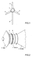
FIG. 1 is a front view of a horizontal-axis wind turbine of an embodiment of the present invention. -
FIG. 2 is a partial enlarged view of the connection section between the hub and a blade of a horizontal-axis wind turbine of an embodiment of the present invention. -
FIG. 3 is a partial cross-sectional drawing of a cross section of the connection section between the hub and blade taken through the pitch axis of a horizontal-axis wind turbine of an embodiment of the present invention, and shows the pitch drive mechanism. -
FIG. 4 is a partial cross-sectional drawing of a cross section of the connection section between the hub and a blade taken through the pitch axis of a horizontal-axis wind turbine of an embodiment of the present invention, and shows the arrangement of pitch drive mechanism that differs from that ofFIG. 3 . -
FIG. 5 is a partial cross-sectional drawing of a cross section of the connection section between the hub and a blade taken through the pitch axis of a horizontal-axis wind turbine of an embodiment of the present invention, and shows a hub-side interposed section angle sensor, and a blade-side interposed section angle sensor. -
FIG. 6 is a cross-sectional drawing of a cross section of the connection section between the hub and a blade taken perpendicular to the pitch axis of a horizontal-axis wind turbine of an embodiment of the present invention. -
FIG. 7 is a partial cross-sectional drawing of a cross section of the connection section between the hub and a blade of a horizontal-axis wind turbine of an embodiment of the present invention taken through the pitch axis, and shows a hub side blade angle sensor. -
FIG. 8 is a front view that shows the strong-wind idling state when there is partial failure of the horizontal-axis wind turbine of an embodiment of the present invention. -
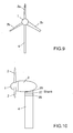
FIG. 9 is a front view that shows the high-wind idling state when there is partial failure of a conventional horizontal-axis wind turbine. -
FIG. 10 is a side view of the horizontal-axis wind turbine of an embodiment of the present invention. -
FIG. 11 is a partial cross-sectional drawing of the connection section between the tower and nacelle taken through the yaw axis of the horizontal-axis wind turbine of an embodiment of the present invention, and shows the yaw drive mechanism. -
FIG. 12 is a cross-sectional drawing of a cross section of the connection section between the tower and the nacelle taken perpendicular to the yaw axis of a horizontal-axis wind turbine of an embodiment of the present invention. - The preferred embodiment of the present invention will be explained below with reference to the accompanying drawings. The following is a preferred embodiment of the present invention and does not limit the invention.
- The horizontal-axis wind turbine of this embodiment as shown in
FIG. 1 comprises a rotor having ahub 1 andblades 2. The rotor of this embodiment is a rotor having threeblades 2. The number of the blades of the rotor to which the present invention can be applied can be one blade or two or more blades. - The horizontal-axis wind turbine of this embodiment further comprises a nacelle 3 (see
FIG. 10 ) that supports the rotor by way of a main shaft (not shown in the figure) that is connected to thehub 1 such that it can rotate freely, and atower 4 that supports thenacelle 3 such that yaw rotation is possible. - Next, the pitch drive-control mechanism of this embodiment will be explained.
- As illustrated in
FIG. 2 andFIG. 3 , aninternal ring gear 8 is attached to thehub 12 by way of abearing unit 5, and aninternal ring gear 9 is attached to ablade 2 by way of abearing unit 6. The bearingunits blade 2. - The
outer race section 5a of thebearing unit 5 is fastened to thehub 1, theouter race 6a of thebearing unit 6 is fastened to theblade 2, and theinner race 5b of thebearing unit 5 and theinner race 6b of thebearing unit 6 are fastened together by way of ashank 7. Theshank 7 is a ring-shaped connection part, and is used when necessary. As known, bearings are held between theouter races 5a (6a) andinner races 5b (6b) so that relative rotation is possible. - As can be seen from the explanation above, the integrated section that comprises the
inner race 5b,inner race 6b andshank 7 forms an interposed section that can rotate freely around the pitch axis PA of theblade 2 with respect to both thehub 1 andblade 2. Thehub 1 andblade 2 are connected by way of this interposedsection - A hub-side interposed section drive unit (pitch drive-control mechanism) that rotates the interposed
section hub 1 comprises thering gear 8 andmotor 10, etc. Thering gear 8 is a ring-shaped internal gear that is fastened to the inside of theinner race 5b. The body of themotor 10 is fastened to thehub 1, and apinion gear 10b that is installed on theoutput shaft 10a of themotor 10 engages with thering gear 8. - A blade-side interposed section drive unit (pitch drive-control mechanism) that rotates the
blade 2 relative to the interposedsection ring gear 9 andmotor 11, etc. Thering gear 9 is a ring-shaped internal gear that is fastened to the inside of theinner race 6b. The body of themotor 11 is fastened to theblade 2, and apinion gear 11b that is installed on theoutput shaft 11a of themotor 11 engages with thering gear 9. - In this embodiment, as shown in
FIG. 3 , the hub-side interposed section drive unit and blade-side interposed section drive unit were arranged on the inside of thehub 1,blade 2 andbearing units FIG. 4 is an example of arranging the hub-side interposed section drive unit on the outside. In the example ofFIG. 4 , theouter race 5a of thebearing unit 5, theinner race 6b of thebearing unit 6 and theshank 7 are integrated together to form an interposed section, anexternal ring gear 12 is fastened to the outside of theouter race 5a and thering gear 12 engages with thepinion gear 10b of themotor 10. - Furthermore, as illustrated in
FIG. 5 , the horizontal-axis wind turbine of this embodiment comprises: a hub-side interposedsection angle sensor 13, which detects the angle of the interposedsection section angle sensor 14, which detects the angle of theblade 2 around the pitch axis PA with respect to the interposedsection - The
angle sensors angle sensor 13 is fastened to thehub 1. Apinion gear 13b that is installed on theinput shaft 13a of theangle sensor 13 engages with thering gear 8. The body of theangle sensor 14 is fastened to theblade 2. A pinion gear 14b that is installed on theinput shaft 14a of theangle sensor 14 engages with thering gear 9. Theinput shafts angle sensors - In order that there is no interference between the
motor 10 andangle sensor 13 and between themotor 11 andangle sensor 14, they may be arranged at different angular positions as shown inFIG. 6 , for example. - Moreover, as shown in
FIG. 7 , the horizontal-axis wind turbine of this embodiment comprises a hub-sideblade angle sensor 15 that directly detects the angle of theblade 2 around the pitch axis PA of theblade 2 with respect to thehub 1. Theangle sensor 15 is a rotary encoder. The body of theangle sensor 15 is fastened to thehub 1. A pinion gear 15b that is installed on theinput shaft 15a of theangle sensor 15 engages with thering gear 9. Theinput shaft 15a is driven and rotated by the ring gears 8, 9, and theangle sensor 15 outputs a signal that corresponds to that amount of rotation. - In order that the
angle sensor 15 does not interfere with themotors angle sensors - The hub-side
blade angle sensor 15 may be used instead or together with the hub-side interposedsection angle sensor 13 and blade-side interposedsection angle sensor 14. - Furthermore, a control unit 35 (a representative example shown in
Fig. 3 ) is installed in the horizontal-axis wind turbine of this embodiment. Thecontrol unit 35 comprises a pitch control means (pitch control unit) and a gear engagement position control means (gear engagement position control unit), and executes the control operations described below. - The
control unit 35 functions as a pitch control unit. - By adding up detected values from the hub-side interposed
section angle sensor 13 and the blade-side interposedsection angle sensor 14, thecontrol unit 35 calculates the angle of theblade 2 around the pitch axis PA with respect to thehub 1, or in other words, the pitch angle of theblade 2. Thecontrol unit 35 also calculates the pitch angle of theblade 2 based on the detected value from the hub-sideblade angle sensor 15. - When performing control to change the angle of the
blade 2 to a target pitch angle, thecontrol unit 35 controls both or either one of the hub-side interposed section drive unit (motor 10) and the blade-side interposed section drive unit (motor 11) so that the pitch angle of theblade 2 that is calculated as described above becomes the target pitch angle. When controlling both drive units, thecontrol unit 35 distributes the amount to change the angle by a 1:1 shared ratio. When controlling either one of the drive units, thecontrol unit 35 alternately uses one of the drives by alternating the drive unit after every specified time interval or after every specified drive amount. Through this control, it is possible to evenly use the hub-side interposed section drive unit (motor 10) and the blade-side interposed section drive unit (motor 11). - In this embodiment, three
angle sensors angle sensors control unit 35 can obtain the pitch angle of theblade 2 from theangle sensor 15, and likewise, when theangle sensor 15 breaks down or does not indicate an accurate value, thecontrol unit 35 can obtain the pitch angle of theblade 2 from theangle sensors - In addition, when the
control unit 35 is in the control mode for controlling both the hub-side interposed section drive unit (motor 10) and the blade-side interposed section drive unit (motor 11), and it becomes impossible to operate one of the hub-side interposed section drive unit (motor 10) and the blade-side interposed section drive unit (motor 11), thecontrol unit 35 switches to the control mode for controlling the pitch angle of theblade 2 by just controlling the operable drive unit. - Moreover, when the
control unit 35 is in the control mode for controlling the pitch angle of theblade 2 by controlling just the hub-side interposed section drive unit (motor 10), and operation of the hub-side interposed section drive unit (motor 10) becomes impossible, thecontrol unit 35 switches to the control mode for controlling the pitch angle of theblade 2 by controlling just the operable blade-side interposed section drive unit (motor 11). - Furthermore, when the
control unit 35 is in the control mode for controlling the pitch angle of theblade 2 by controlling just the blade-side interposed section drive unit (motor 11), and operation of the blade-side interposed section drive unit (motor 11) becomes impossible, thecontrol unit 35 switches to the control mode for controlling the pitch angle of theblade 2 by controlling just the operable hub-side interposed section drive unit (motor 10). - In one form of control, when one of the hub-side interposed section drive unit (motor 10) and blade-side interposed section drive unit (motor 11) becomes inoperable, the
control unit 35 switches to the necessary control mode as described above, and continues normal operation of the wind turbine, and during strong winds when the wind turbine must be idled, feathers theblades FIG. 8 as idling operation during strong wind. - In another form of control, when one of the hub-side interposed section drive unit (motor 10) and blade-side interposed section drive unit (motor 11) cannot be operated, the
control unit 35 switches to the necessary control mode as described above, feathers theblades FIG. 8 and waits until the cause of the trouble is eliminated by maintenance personnel. - In a conventional pitch drive control system, when the wind turbine becomes disabled during operation, continuing normal operation of the wind turbine becomes difficult from the aspect of the decrease in efficiency and increase in load, and as shown in
FIG. 9 , it is not possible for the pitch drive control system to feather theblade 2c that became disabled, and even though theother blades - However, in this embodiment, as long as one of the hub-side interposed section drive unit (motor 10) and blade-side interposed section drive unit (motor 11) is operable, it is possible to continue normal operation of the wind turbine, as well as it is possible to feather the
blades - The
control unit 35 also functions as a gear engagement position control unit. - The control unit controls both the hub-side interposed section drive unit (motor 10) and the blade-side interposed section drive unit (motor 11) so that the direction of relative rotation of the interposed
section hub 1 is opposite the direction of relative rotation of theblade 2 with respect to the interposedsection ring gear 8 and thepinion gear 10b, and the engagement position of thering gear 9 andpinion gear 11b by that offset amount. - By relatively rotating the interposed
section hub 1, while at the same time relatively rotating theblade 2 with respect to the interposedsection section blade 2 with respect to thehub 1, or in other words, without changing the pitch angle of theblade 2. - According to the underlying principle, it is possible to change the engagement positions of the ring gears 8, 9 and the engaging
gears - Next, yaw drive-control mechanism of this embodiment will be explained.
- As shown in
FIG. 10 andFIG 11 , aninternal ring gear 28 is installed at the top end of thetower 4 by way of a bearingunit 25, and aninternal ring gear 29 is installed on thenacelle 3 by way of a bearingunit 26. The bearingunits nacelle 3. - The
outer race 25a of the bearingunit 25 is fastened to thetower 4, and theouter race 26a of the bearingunit 26 is fastened to thenacelle 3, and theinner race 25b of the bearingunit 25 and theinner race 26b of the bearingunit 26 are fastened together by way of ashank 27. Theshank 27 is a ring-shaped connection part, and is used as necessary. As is well known, bearings are held between theouter races 25a (26a) and theinner races 25b (26b) of the bearing units 25 (26) such that there is relative rotation. - As can be seen from the explanation above, the integrated section that is formed from the
inner race 25b,inner race 26b andshank 27 forms an interposed section that can rotate freely around the yaw axis YA of thenacelle 3 with respect to both thetower 4 and thenacelle 3. Thetower 4 andnacelle 3 are connected by way of the interposedsection - A tower-side interposed section drive unit that rotates the interposed
section tower 4 comprises aring gear 28 andmotor 30, etc. Thering gear 28 is an internal ring-shaped gear that is fastened to the inside of theinner race 25b. The body of themotor 30 is fastened to thetower 4, and apinion gear 30b that is installed on theoutput shaft 30a of themotor 30 engages with thering gear 28. - A nacelle-side interposed section drive unit that rotates the
nacelle 3 relative to the interposedsection ring gear 29 andmotor 31, etc. Thering gear 29 is an internal ring-shaped gear that is fastened to the inside of theinner race 26b. The body of themotor 31 is fastened to thenacelle 3, and apinion gear 31b that is installed on theoutput shaft 31a of themotor 31 engages with thering gear 29. - In this embodiment, the tower-side interposed section drive unit and nacelle-side interposed section drive unit are arranged on the inside of the
tower 4,nacelle 3 and bearingunits FIG. 11 , however, it is possible to use other various arrangements such as locating one or both on the outside. Similar to the illustration ofFig. 4 (by replacing thehub 1 with thetower 4, and theblade 2 with thenacelle 3 inFIG. 4 ), the tower-side interposed section drive unit can be located on the outside. - Moreover, similar to the construction shown in
FIG. 5 (by replacing thehub 1 with thetower 4, and theblade 2 with the nacelle 3), the horizontal-axis wind turbine of this embodiment comprises a tower-side interposedsection angle sensor 33 that detects the angle of the interposedsection tower 4, and a nacelle-side interposedsection angle sensor 34 that detects the angle of thenacelle 3 around the yaw axis YA with respect to the interposedsection - As illustrated in
FIG. 12 , in order that there is no interference between themotor 30 andangle sensor 33, and themotor 31 andangle sensor 34, themotors angle sensors - Furthermore, similar to the construction shown in
FIG. 7 (by replacing thehub 1 with thetower 4, and theblade 2 with the nacelle 3), the horizontal-axis wind turbine of this embodiment comprises a tower-side nacelle angle sensor (not shown in the figure) that directly detects the angle of thenacelle 3 around the yaw axis YA with respect to thetower 4. - The tower-side nacelle angle sensor is located at a different angular position so that it does not interfere with the
motors angle sensors - The tower-side nacelle angle sensor can be used instead of or together with the tower-side interposed
section angle sensor 33 and nacelle-side interposedsection angle sensor 34. - A
control unit 35 functions as a yaw control unit along with the yaw drive-control mechanism. - The
control unit 35 calculates the angle of thenacelle 3 around the yaw axis with respect to thetower 4, or in other words, calculates the yaw angle of thenacelle 3 based on the sum of the detected value from the tower-side interposedsection angle sensor 33 and the detected value from the nacelle-side interposedsection angle sensor 34. - The
control unit 35 also calculates the yaw angle of thenacelle 3 based on the detected value from the tower-side nacelle angle sensor. - When performing control to change the angle of the
nacelle 3 to a target yaw angle, thecontrol unit 35 controls both or just one of the tower-side interposed section drive unit (motor 30) and nacelle-side interposed section drive unit (motor 31) so that the yaw angle of thenacelle 3, which is calculated as described above, becomes the target angle. When thecontrol unit 35 controls both, the amount of angle change is distributed among both at a sharing ratio of 1:1. When controlling only one, thecontrol unit 35 alternately uses each drive unit by alternating the drive unit used after every specified time interval or specified total drive amount. Through this kind of control, it is possible to evenly use the tower-side interposed section drive unit (motor 30) and nacelle-side interposed section drive unit (motor 31). - In this embodiment, three angle sensors are used, so even in the case where the tower-side interposed
section angle sensor 33 and nacelle-side interposedsection angle sensor 34 break down or do not indicate the correct value, thecontrol unit 35 is able to know the yaw angle of thenacelle 3 from the tower-side nacelle angle sensor, and conversely, when the tower-side nacelle angle sensor breaks down and does not indicate the correct value, thecontrol unit 35 is able to know the yaw angle of thenacelle 3 from the tower-side interposedsection angle sensor 33 and nacelle-side interposedsection angle sensor 34. - In addition, when the
control unit 35 is in the control mode for controlling both the tower-side interposed section drive unit (motor 30) and nacelle-side interposed section drive unit (motor 31), and one of the tower-side interposed section drive unit (motor 30) and nacelle-side interposed section drive unit (motor 31) becomes inoperable, thecontrol unit 35 switches to the control mode for controlling the yaw angle of thenacelle 3 by controlling just the one operable drive unit. - Moreover, when the
control unit 35 is in the control mode for controlling only the tower-side interposed section drive unit (motor 30) for controlling the yaw angle of thenacelle 3, and the tower-side interposed section drive unit (motor 30) becomes inoperable, thecontrol unit 35 switches to the control mode for controlling the yaw angle of thenacelle 3 by just controlling the operable nacelle-side interposed section drive unit (motor 31). - Furthermore, when the
control unit 35 is in the control mode for controlling only the nacelle-side interposed section drive unit (motor 31) for controlling the yaw angle of thenacelle 3, and the nacelle-side interposed section drive unit (motor 31) becomes inoperable, thecontrol unit 35 switches to the control mode for controlling the yaw angle of thenacelle 3 by just controlling the operable tower-side interposed section drive unit (motor 30). - When one of the tower-side interposed section drive unit (motor 30) and nacelle-side interposed section drive unit (motor 31) becomes inoperable, the
control unit 35 switches to one of the control modes described above as necessary and is able to continue normal operation of the wind turbine, and in the case of strong wind when idling is necessary, is able to perform the idling operation for strong wind. Therefore the rate of operation and maintainability of the wind turbine is improved. - Moreover, the
control unit 35 functions as a gear engagement position control unit. - The
control unit 35 controls both the tower-side interposed section drive unit (motor 30) and nacelle-side interposed section drive unit (motor 31) so that the direction of relative rotation of the interposedsection tower 4 and the direction of relative rotation of thenacelle 3 with respect to the interposedsection ring gear 28 andpinion gear 30b and gear engagement position of thering gear 29 andpinion gear 31b. - By relatively rotating the interposed
section tower 4, while at the same time relatively rotating thenacelle 3 with respect to the interposedsection section nacelle 3 with respect to thetower 4, or in other words, without changing the yaw angle of thenacelle 3. - According to the underlying principle, it is possible to change the engagement positions of the ring gears 28, 29 and the engaging
gears
Claims (10)
- A horizontal-axis wind turbine having a rotor with a hub (1) and one or more blades (2), and a pitch control mechanism for driving and controlling a pitch angle of each of the blades (2) independently; characterized in that:the hub (1) and the blade (2) are connected by an interposed section which can freely rotate around the pitch axis (PA) of the blade (2) with respect to both the hub (1) and the blade; andthe pitch control mechanism includes:a hub-side interposed section drive unit that relatively rotates the interposed section with respect to the hub (1), and a blade-side interposed section drive unit that relatively rotates the blade (2) with respect to the interposed section.
- The horizontal-axis wind turbine according to claim 1, further characterized by:a pitch control unit for controlling the pitch control mechanism, the control pitch unit being configured to control an angle of the blade (2) around the pitch axis (PA) with respect to the hub (1) whether controlling both or just one of the hub-side interposed section drive unit and blade-side interposed section drive unit for one blade.
- The horizontal-axis wind turbine according to claim 2, characterized by further having:a hub-side interposed section angle sensor (13) that detects an angle of the interposed section around the pitch axis (PA) with respect to the hub (1), anda blade-side interposed section angle sensor (14) that detects an angle of the blade (2) around the pitch axis (PA) with respect to the interposed section; whereinthe pitch control unit is configured to control an angle of the blade (2) around the pitch axis (PA) with respect to the hub (1) whether controlling both or just one of the hub-side interposed section drive unit and blade-side interposed section drive unit, based on the detected value from the hub-side interposed section angle sensor (13) and the detected value from the blade-side interposed section angle sensor (14).
- The horizontal-axis wind turbine according to claim 2 or claim 3, further characterized by:a hub-side blade angle sensor (15) that directly detects an angle of the blade (2) around the pitch axis (PA) with respect to the hub (1); whereinthe pitch control unit is configured to control the angle around the pitch axis (PA) of the blade (2) with respect to the hub (1) whether controlling both or just one of the hub-side interposed section drive unit and blade-side interposed section drive unit based on the detected value from the hub-side blade angle sensor (15).
- The horizontal-axis wind turbine according to claim 1, characterized in that:each of the hub-side interposed section drive unit and the blade-side interposed section drive unit includes a ring gear (8, 9, 12) that is fastened to the hub (1), the interposed section or the blade (2) and arranged with the pitch axis (PA) being a center axis thereof, and a gear that engages with the ring gear (8, 9, 12), as a transmission mechanism section; andthe horizontal-axis wind turbine further having:a gear engagement position control unit for controlling both the hub-side interposed section drive unit and blade-side interposed section drive unit so that a direction of relative rotation of the interposed section with respect to the hub (1), and a direction of relative rotation of the blade (2) with respect to the interposed section are in opposite directions, and changes a gear engagement position of the ring gear (8, 9, 12) and the gear by that offset amount.
- A horizontal-axis wind turbine having a rotor with a hub (1) and one or more blades, a nacelle (3) that supports the rotor by way of a shaft that is connected to the hub (1) so that the rotor can rotate freely, a tower (4) that supports the nacelle (3) such that the nacelle (3) is capable of free yaw rotation, and a yaw control mechanism for driving and controlling a yaw angle of the nacelle (3); characterized in that:the hub (1) and the nacelle (3) are connected by an interposed section which can freely rotate around the yaw axis (YA) of the nacelle (3) with respect to both the tower (4) and the nacelle (3); andthe yaw control mechanism includes:a tower-side interposed section drive unit that relatively rotates the interposed section with respect to the tower (4), anda nacelle-side interposed section drive unit that relatively rotates the nacelle (3) with respect to the interposed section.
- The horizontal-axis wind turbine according to claim 6, characterized in that:a yaw control unit for controlling the yaw control mechanism, the yaw control unit being configured to control an angle of the nacelle (3) around the yaw axis (YA) with respect to the tower (4) whether controlling both or just one of the tower-side interposed section drive unit and nacelle-side interposed section drive unit for one blade.
- The horizontal-axis wind turbine according to claim 7, further characterized by:a tower-side interposed section angle sensor (33) that detects an angle of the interposed section around the yaw axis (YA) with respect to the tower (4), anda nacelle-side interposed section angle sensor (34) that detects an angle of the nacelle (3) around the yaw axis (YA) with respect to the interposed section; whereinthe yaw control unit is configured to control an angle of the nacelle (3) around the yaw axis (YA) with respect to the tower (4) whether controlling both or just one of the tower-side interposed section drive unit and nacelle-side interposed section drive unit based on the detected value from the tower-side interposed section angle sensor (33) and the detected value from the nacelle-side interposed section angle sensor (34).
- The horizontal-axis wind turbine according to claim 7 or claim 8, further characterized by:a tower-side nacelle angle sensor that directly detects an angle of the nacelle (3) around the yaw axis (YA) with respect to the tower (4); whereinthe yaw control unit is configured to control the angle of the nacelle (3) around the yaw axis (YA) with respect to the tower (4) whether controlling both or just one of the tower-side interposed section drive unit and nacelle-side interposed section drive unit based on the detected value from the tower-side nacelle angle sensor.
- The horizontal-axis wind turbine according to claim 6, characterized in that:each of the tower-side interposed section drive unit and the nacelle-side interposed section drive unit includes a ring gear (8, 9, 12) that is fastened to the tower (4), the interposed section or the nacelle (3) and arranged with the yaw axis (YA) being a center axis thereof, and a gear that engages with the ring gear (8, 9, 12), as a transmission mechanism section; andthe horizontal-axis wind turbine further having:a gear engagement position control unit for controlling both the tower-side interposed section drive unit and nacelle-side interposed section drive unit so that a direction of relative rotation of the interposed section with respect to the tower (4) and a direction of relative rotation of the nacelle (3) with respect to the interposed section are in opposite directions, and changes a gear engagement position of the ring gear (8, 9, 12) and the gear by that offset amount.
Applications Claiming Priority (1)
| Application Number | Priority Date | Filing Date | Title |
|---|---|---|---|
| JP2009124132A JP5284872B2 (en) | 2009-05-22 | 2009-05-22 | Horizontal axis windmill |
Publications (3)
| Publication Number | Publication Date |
|---|---|
| EP2253841A2 true EP2253841A2 (en) | 2010-11-24 |
| EP2253841A3 EP2253841A3 (en) | 2014-03-05 |
| EP2253841B1 EP2253841B1 (en) | 2016-07-27 |
Family
ID=42286472
Family Applications (1)
| Application Number | Title | Priority Date | Filing Date |
|---|---|---|---|
| EP10163503.5A Active EP2253841B1 (en) | 2009-05-22 | 2010-05-20 | Horizontal axis wind turbine |
Country Status (3)
| Country | Link |
|---|---|
| US (1) | US8459946B2 (en) |
| EP (1) | EP2253841B1 (en) |
| JP (1) | JP5284872B2 (en) |
Cited By (9)
| Publication number | Priority date | Publication date | Assignee | Title |
|---|---|---|---|---|
| GB2486406A (en) * | 2010-12-08 | 2012-06-20 | Vestas Wind Sys As | Wind turbine pitch system with plural axially spaced pitch gears |
| WO2012146751A2 (en) * | 2011-04-27 | 2012-11-01 | Aktiebolaget Skf | Pitch drive system and method |
| WO2013097851A1 (en) * | 2011-12-30 | 2013-07-04 | Vestas Wind Systems A/S | A pitch system for a wind turbine |
| EP2474735A3 (en) * | 2010-12-08 | 2014-12-31 | Vestas Wind Systems A/S | Mounting arrangement for pitch gear |
| EP2697508B1 (en) | 2011-04-14 | 2015-04-15 | Suzlon Energy GmbH | Device and method for determining a blade position and for ending a safety run |
| EP3034867A1 (en) * | 2014-12-19 | 2016-06-22 | ALSTOM Renewable Technologies | Fretting corrosion and methods of operating a wind turbine |
| EP3450745A1 (en) * | 2017-09-04 | 2019-03-06 | Siemens Gamesa Renewable Energy A/S | Method of operating a wind turbine yaw assembly |
| EP3670901A1 (en) * | 2018-12-18 | 2020-06-24 | Nordex Energy Spain, S.A.U. | Method and device to extend the life cycle of a wind turbine |
| CN116641836A (en) * | 2023-06-14 | 2023-08-25 | 上海玻璃钢研究院东台有限公司 | Blade on horizontal axis wind turbine |
Families Citing this family (13)
| Publication number | Priority date | Publication date | Assignee | Title |
|---|---|---|---|---|
| US20060205554A1 (en) * | 2003-08-12 | 2006-09-14 | Osamu Nohara | Speed reducer for use in yaw drive apparatus for wind power generation apparatus, and yaw drive method and apparatus for wind power generation apparatus using the speed reducer |
| CN102022262B (en) * | 2009-08-25 | 2013-12-11 | 维斯塔斯风力系统集团公司 | Yaw system for a nacelle of a wind turbine and wind turbine |
| CN103221685A (en) * | 2010-11-26 | 2013-07-24 | 维斯塔斯风力系统有限公司 | A pitch system for a wind turbine |
| EP2707609B1 (en) * | 2011-05-13 | 2015-09-02 | Aktiebolaget SKF | Spacer for rolling bearing, notably used in a wind turbine |
| EP2707610B1 (en) * | 2011-05-13 | 2015-09-30 | Aktiebolaget SKF | Spacer for rolling bearing, notably used in a wind turbine |
| EP2679816B1 (en) * | 2012-06-27 | 2015-08-19 | ALSTOM Renewable Technologies | A pitch system for a wind turbine rotor |
| US9388792B2 (en) | 2013-03-15 | 2016-07-12 | Frontier Wind, Llc | Distributed control system |
| DE202013104310U1 (en) * | 2013-09-20 | 2014-12-23 | Rolf Rohden | Rotor blade, wind turbine and wind turbine park |
| JP6006706B2 (en) * | 2013-10-07 | 2016-10-12 | エコ・パワー株式会社 | Wind turbine monitoring system, wind power generation system, wind turbine monitoring method, and wind turbine monitoring program |
| JP6247957B2 (en) * | 2014-02-26 | 2017-12-13 | 三菱重工業株式会社 | Yaw control system and yaw control method for wind turbine generator |
| JP6345503B2 (en) * | 2014-06-25 | 2018-06-20 | 株式会社日立製作所 | Horizontal axis type windmill and its standby method |
| US10502194B2 (en) * | 2016-05-27 | 2019-12-10 | General Electric Company | Wind turbine bearings |
| EP3269974B1 (en) * | 2016-07-12 | 2022-01-05 | Siemens Gamesa Renewable Energy A/S | Wind turbine with rotor blade pitch arrangement |
Citations (1)
| Publication number | Priority date | Publication date | Assignee | Title |
|---|---|---|---|---|
| JP2005030263A (en) | 2003-07-10 | 2005-02-03 | Ts Corporation | Pitch angle control device of windmill blade |
Family Cites Families (14)
| Publication number | Priority date | Publication date | Assignee | Title |
|---|---|---|---|---|
| JPS62284969A (en) * | 1986-06-03 | 1987-12-10 | Yamaha Motor Co Ltd | Pitch converter for propeller type wind power generator |
| JPH04125675U (en) * | 1991-04-26 | 1992-11-16 | 住友精密工業株式会社 | Wind turbine variable pitch mechanism |
| DE19948997B4 (en) * | 1999-10-11 | 2005-04-14 | Aerodyn Engineering Gmbh | Single blade adjustment for wind turbines |
| DE10140793A1 (en) * | 2001-08-20 | 2003-03-06 | Gen Electric | Device for adjusting the rotor blade of a rotor of a wind turbine |
| DE10141098A1 (en) * | 2001-08-22 | 2003-03-06 | Gen Electric | Wind turbine |
| JP4324425B2 (en) * | 2003-07-17 | 2009-09-02 | 富士重工業株式会社 | Horizontal axis wind turbine and control method thereof |
| DE102004023773B3 (en) * | 2004-05-11 | 2005-11-17 | Repower Systems Ag | Wind turbine |
| DE102004027992B4 (en) * | 2004-06-09 | 2011-06-16 | Kenersys Gmbh | Wind turbine with an azimuth system |
| DE102004046260B4 (en) * | 2004-09-23 | 2007-05-16 | Nordex Energy Gmbh | Method for operating a device for adjusting a blade pitch and an adjustment |
| EP1647708A1 (en) * | 2004-10-14 | 2006-04-19 | General Electric Company | Pitch drive system for a wind turbine |
| JP4690776B2 (en) * | 2005-05-31 | 2011-06-01 | 富士重工業株式会社 | Horizontal axis windmill |
| ES2279725B1 (en) * | 2006-02-09 | 2008-07-16 | Hydra-Power, S.L. | DEVICE FOR THE CONTROL OF THE SHOVELS OF AN AEROGENERATOR. |
| FR2911644B1 (en) * | 2007-01-23 | 2012-06-01 | Snecma | TURBOPROPULSEUR COMPRISING A PROPELLED PROPELLER OF BLADES WITH ADJUSTABLE ORIENTATION. |
| JPWO2009150715A1 (en) * | 2008-06-10 | 2011-11-04 | 三菱重工業株式会社 | Wind power generator and construction method thereof |
-
2009
- 2009-05-22 JP JP2009124132A patent/JP5284872B2/en not_active Expired - Fee Related
-
2010
- 2010-05-20 EP EP10163503.5A patent/EP2253841B1/en active Active
- 2010-05-21 US US12/785,078 patent/US8459946B2/en active Active
Patent Citations (1)
| Publication number | Priority date | Publication date | Assignee | Title |
|---|---|---|---|---|
| JP2005030263A (en) | 2003-07-10 | 2005-02-03 | Ts Corporation | Pitch angle control device of windmill blade |
Cited By (18)
| Publication number | Priority date | Publication date | Assignee | Title |
|---|---|---|---|---|
| EP2474735A3 (en) * | 2010-12-08 | 2014-12-31 | Vestas Wind Systems A/S | Mounting arrangement for pitch gear |
| US9261071B2 (en) | 2010-12-08 | 2016-02-16 | Vestas Wind Systems A/S | Mounting arrangement for pitch gear |
| GB2486406A (en) * | 2010-12-08 | 2012-06-20 | Vestas Wind Sys As | Wind turbine pitch system with plural axially spaced pitch gears |
| EP2697508B1 (en) | 2011-04-14 | 2015-04-15 | Suzlon Energy GmbH | Device and method for determining a blade position and for ending a safety run |
| WO2012146751A2 (en) * | 2011-04-27 | 2012-11-01 | Aktiebolaget Skf | Pitch drive system and method |
| WO2012146752A3 (en) * | 2011-04-27 | 2013-04-04 | Aktiebolaget Skf | Rotational support of a wind turbine blade |
| WO2012146751A3 (en) * | 2011-04-27 | 2013-04-04 | Aktiebolaget Skf | Pitch drive system and method |
| US9803620B2 (en) | 2011-12-30 | 2017-10-31 | Vestas Wind Systems A/S | Pitch system for a wind turbine |
| WO2013097851A1 (en) * | 2011-12-30 | 2013-07-04 | Vestas Wind Systems A/S | A pitch system for a wind turbine |
| EP3034867A1 (en) * | 2014-12-19 | 2016-06-22 | ALSTOM Renewable Technologies | Fretting corrosion and methods of operating a wind turbine |
| CN107278241A (en) * | 2014-12-19 | 2017-10-20 | 阿尔斯通可再生风能技术私人有限公司 | Fretting corrosion and the method for operation wind turbine |
| WO2016097225A1 (en) * | 2014-12-19 | 2016-06-23 | Alstom Renewable Technologies Wind B.V. | Fretting corrosion and methods of operating a wind turbine |
| EP3450745A1 (en) * | 2017-09-04 | 2019-03-06 | Siemens Gamesa Renewable Energy A/S | Method of operating a wind turbine yaw assembly |
| US10634119B2 (en) | 2017-09-04 | 2020-04-28 | Siemens Gamesa Renewable Energy A/S | Method of operating a wind turbine yaw assembly |
| EP3670901A1 (en) * | 2018-12-18 | 2020-06-24 | Nordex Energy Spain, S.A.U. | Method and device to extend the life cycle of a wind turbine |
| US11933268B2 (en) | 2018-12-18 | 2024-03-19 | Nordex Energy Spain S.A.U. | Method and device to extend the life cycle of a wind turbine |
| CN116641836A (en) * | 2023-06-14 | 2023-08-25 | 上海玻璃钢研究院东台有限公司 | Blade on horizontal axis wind turbine |
| CN116641836B (en) * | 2023-06-14 | 2023-12-08 | 上海玻璃钢研究院东台有限公司 | Horizontal axis wind driven generator with adjustable blade angle |
Also Published As
| Publication number | Publication date |
|---|---|
| EP2253841A3 (en) | 2014-03-05 |
| EP2253841B1 (en) | 2016-07-27 |
| JP2010270703A (en) | 2010-12-02 |
| JP5284872B2 (en) | 2013-09-11 |
| US8459946B2 (en) | 2013-06-11 |
| US20100296932A1 (en) | 2010-11-25 |
Similar Documents
| Publication | Publication Date | Title |
|---|---|---|
| US8459946B2 (en) | Horizontal axis wind turbine | |
| CN102287333B (en) | Gear train and the wind turbine and the maintaining method that comprise such gear train | |
| EP2458200B1 (en) | Wind turbine rotor comprising a pitch bearing mechanism and a method of repair therefore | |
| EP2390500B1 (en) | Systems and methods for monitoring a condition of a rotor blade for a wind turbine | |
| EP2242925B1 (en) | A drive train for a wind turbine | |
| EP2375068B1 (en) | Systems and methods for monitoring a structural health of a wind turbine | |
| US8242618B2 (en) | Wind turbine generator | |
| US6799947B2 (en) | Bearing for an adjustable rotor blade on a wind energy plant | |
| US20100133827A1 (en) | Method and system for controlling a wind turbine | |
| EP3296564B1 (en) | Drive device for wind turbines, drive device unit for wind turbines, and wind turbine | |
| US20130008242A1 (en) | Abrasion sensing device, wind turbine generation apparatus including the same, and abrasion sensing method | |
| US20130039768A1 (en) | Rotary connection of a rotor blade to the rotor hub of a wind energy plant | |
| JP5581313B2 (en) | Pitch control device for windmill | |
| EP2352918B1 (en) | Device for adjustment of a rotor blade, wind energy converter, and method for adjusting a rotor blade | |
| EP2317130B1 (en) | Systems and methods for assembling a pitch assembly for use in a wind turbine | |
| EP2783104B1 (en) | A wind turbine comprising a blade pitch system | |
| EP2975262B1 (en) | Wind power generation facility | |
| JP5557937B2 (en) | Horizontal axis windmill | |
| US20160010625A1 (en) | Blade pitching |
Legal Events
| Date | Code | Title | Description |
|---|---|---|---|
| PUAI | Public reference made under article 153(3) epc to a published international application that has entered the european phase |
Free format text: ORIGINAL CODE: 0009012 |
|
| AK | Designated contracting states |
Kind code of ref document: A2 Designated state(s): AL AT BE BG CH CY CZ DE DK EE ES FI FR GB GR HR HU IE IS IT LI LT LU LV MC MK MT NL NO PL PT RO SE SI SK SM TR |
|
| AX | Request for extension of the european patent |
Extension state: BA ME RS |
|
| RAP1 | Party data changed (applicant data changed or rights of an application transferred) |
Owner name: HITACHI, LTD. |
|
| PUAL | Search report despatched |
Free format text: ORIGINAL CODE: 0009013 |
|
| AK | Designated contracting states |
Kind code of ref document: A3 Designated state(s): AL AT BE BG CH CY CZ DE DK EE ES FI FR GB GR HR HU IE IS IT LI LT LU LV MC MK MT NL NO PL PT RO SE SI SK SM TR |
|
| AX | Request for extension of the european patent |
Extension state: BA ME RS |
|
| RIC1 | Information provided on ipc code assigned before grant |
Ipc: F03D 7/02 20060101AFI20140130BHEP |
|
| 17P | Request for examination filed |
Effective date: 20140905 |
|
| RAX | Requested extension states of the european patent have changed |
Extension state: RS Payment date: 20140905 Extension state: ME Payment date: 20140905 Extension state: BA Payment date: 20140905 |
|
| RBV | Designated contracting states (corrected) |
Designated state(s): AL AT BE BG CH CY CZ DE DK EE ES FI FR GB GR HR HU IE IS IT LI LT LU LV MC MK MT NL NO PL PT RO SE SI SK SM TR |
|
| 17Q | First examination report despatched |
Effective date: 20141215 |
|
| GRAP | Despatch of communication of intention to grant a patent |
Free format text: ORIGINAL CODE: EPIDOSNIGR1 |
|
| INTG | Intention to grant announced |
Effective date: 20160211 |
|
| GRAS | Grant fee paid |
Free format text: ORIGINAL CODE: EPIDOSNIGR3 |
|
| GRAA | (expected) grant |
Free format text: ORIGINAL CODE: 0009210 |
|
| AK | Designated contracting states |
Kind code of ref document: B1 Designated state(s): AL AT BE BG CH CY CZ DE DK EE ES FI FR GB GR HR HU IE IS IT LI LT LU LV MC MK MT NL NO PL PT RO SE SI SK SM TR |
|
| AX | Request for extension of the european patent |
Extension state: BA ME RS |
|
| REG | Reference to a national code |
Ref country code: GB Ref legal event code: FG4D |
|
| REG | Reference to a national code |
Ref country code: CH Ref legal event code: EP |
|
| REG | Reference to a national code |
Ref country code: AT Ref legal event code: REF Ref document number: 816035 Country of ref document: AT Kind code of ref document: T Effective date: 20160815 |
|
| REG | Reference to a national code |
Ref country code: IE Ref legal event code: FG4D |
|
| REG | Reference to a national code |
Ref country code: DE Ref legal event code: R096 Ref document number: 602010034985 Country of ref document: DE |
|
| REG | Reference to a national code |
Ref country code: LT Ref legal event code: MG4D |
|
| REG | Reference to a national code |
Ref country code: NL Ref legal event code: MP Effective date: 20160727 |
|
| REG | Reference to a national code |
Ref country code: AT Ref legal event code: MK05 Ref document number: 816035 Country of ref document: AT Kind code of ref document: T Effective date: 20160727 |
|
| PG25 | Lapsed in a contracting state [announced via postgrant information from national office to epo] |
Ref country code: HR Free format text: LAPSE BECAUSE OF FAILURE TO SUBMIT A TRANSLATION OF THE DESCRIPTION OR TO PAY THE FEE WITHIN THE PRESCRIBED TIME-LIMIT Effective date: 20160727 Ref country code: FI Free format text: LAPSE BECAUSE OF FAILURE TO SUBMIT A TRANSLATION OF THE DESCRIPTION OR TO PAY THE FEE WITHIN THE PRESCRIBED TIME-LIMIT Effective date: 20160727 Ref country code: LT Free format text: LAPSE BECAUSE OF FAILURE TO SUBMIT A TRANSLATION OF THE DESCRIPTION OR TO PAY THE FEE WITHIN THE PRESCRIBED TIME-LIMIT Effective date: 20160727 Ref country code: IS Free format text: LAPSE BECAUSE OF FAILURE TO SUBMIT A TRANSLATION OF THE DESCRIPTION OR TO PAY THE FEE WITHIN THE PRESCRIBED TIME-LIMIT Effective date: 20161127 Ref country code: NO Free format text: LAPSE BECAUSE OF FAILURE TO SUBMIT A TRANSLATION OF THE DESCRIPTION OR TO PAY THE FEE WITHIN THE PRESCRIBED TIME-LIMIT Effective date: 20161027 Ref country code: NL Free format text: LAPSE BECAUSE OF FAILURE TO SUBMIT A TRANSLATION OF THE DESCRIPTION OR TO PAY THE FEE WITHIN THE PRESCRIBED TIME-LIMIT Effective date: 20160727 Ref country code: IT Free format text: LAPSE BECAUSE OF FAILURE TO SUBMIT A TRANSLATION OF THE DESCRIPTION OR TO PAY THE FEE WITHIN THE PRESCRIBED TIME-LIMIT Effective date: 20160727 |
|
| PG25 | Lapsed in a contracting state [announced via postgrant information from national office to epo] |
Ref country code: SE Free format text: LAPSE BECAUSE OF FAILURE TO SUBMIT A TRANSLATION OF THE DESCRIPTION OR TO PAY THE FEE WITHIN THE PRESCRIBED TIME-LIMIT Effective date: 20160727 Ref country code: PT Free format text: LAPSE BECAUSE OF FAILURE TO SUBMIT A TRANSLATION OF THE DESCRIPTION OR TO PAY THE FEE WITHIN THE PRESCRIBED TIME-LIMIT Effective date: 20161128 Ref country code: ES Free format text: LAPSE BECAUSE OF FAILURE TO SUBMIT A TRANSLATION OF THE DESCRIPTION OR TO PAY THE FEE WITHIN THE PRESCRIBED TIME-LIMIT Effective date: 20160727 Ref country code: PL Free format text: LAPSE BECAUSE OF FAILURE TO SUBMIT A TRANSLATION OF THE DESCRIPTION OR TO PAY THE FEE WITHIN THE PRESCRIBED TIME-LIMIT Effective date: 20160727 Ref country code: BE Free format text: LAPSE BECAUSE OF FAILURE TO SUBMIT A TRANSLATION OF THE DESCRIPTION OR TO PAY THE FEE WITHIN THE PRESCRIBED TIME-LIMIT Effective date: 20160727 Ref country code: GR Free format text: LAPSE BECAUSE OF FAILURE TO SUBMIT A TRANSLATION OF THE DESCRIPTION OR TO PAY THE FEE WITHIN THE PRESCRIBED TIME-LIMIT Effective date: 20161028 Ref country code: AT Free format text: LAPSE BECAUSE OF FAILURE TO SUBMIT A TRANSLATION OF THE DESCRIPTION OR TO PAY THE FEE WITHIN THE PRESCRIBED TIME-LIMIT Effective date: 20160727 Ref country code: LV Free format text: LAPSE BECAUSE OF FAILURE TO SUBMIT A TRANSLATION OF THE DESCRIPTION OR TO PAY THE FEE WITHIN THE PRESCRIBED TIME-LIMIT Effective date: 20160727 |
|
| PG25 | Lapsed in a contracting state [announced via postgrant information from national office to epo] |
Ref country code: EE Free format text: LAPSE BECAUSE OF FAILURE TO SUBMIT A TRANSLATION OF THE DESCRIPTION OR TO PAY THE FEE WITHIN THE PRESCRIBED TIME-LIMIT Effective date: 20160727 Ref country code: RO Free format text: LAPSE BECAUSE OF FAILURE TO SUBMIT A TRANSLATION OF THE DESCRIPTION OR TO PAY THE FEE WITHIN THE PRESCRIBED TIME-LIMIT Effective date: 20160727 |
|
| REG | Reference to a national code |
Ref country code: DE Ref legal event code: R097 Ref document number: 602010034985 Country of ref document: DE |
|
| REG | Reference to a national code |
Ref country code: FR Ref legal event code: PLFP Year of fee payment: 8 |
|
| PG25 | Lapsed in a contracting state [announced via postgrant information from national office to epo] |
Ref country code: SM Free format text: LAPSE BECAUSE OF FAILURE TO SUBMIT A TRANSLATION OF THE DESCRIPTION OR TO PAY THE FEE WITHIN THE PRESCRIBED TIME-LIMIT Effective date: 20160727 Ref country code: DK Free format text: LAPSE BECAUSE OF FAILURE TO SUBMIT A TRANSLATION OF THE DESCRIPTION OR TO PAY THE FEE WITHIN THE PRESCRIBED TIME-LIMIT Effective date: 20160727 Ref country code: SK Free format text: LAPSE BECAUSE OF FAILURE TO SUBMIT A TRANSLATION OF THE DESCRIPTION OR TO PAY THE FEE WITHIN THE PRESCRIBED TIME-LIMIT Effective date: 20160727 Ref country code: BG Free format text: LAPSE BECAUSE OF FAILURE TO SUBMIT A TRANSLATION OF THE DESCRIPTION OR TO PAY THE FEE WITHIN THE PRESCRIBED TIME-LIMIT Effective date: 20161027 Ref country code: CZ Free format text: LAPSE BECAUSE OF FAILURE TO SUBMIT A TRANSLATION OF THE DESCRIPTION OR TO PAY THE FEE WITHIN THE PRESCRIBED TIME-LIMIT Effective date: 20160727 |
|
| PLBE | No opposition filed within time limit |
Free format text: ORIGINAL CODE: 0009261 |
|
| STAA | Information on the status of an ep patent application or granted ep patent |
Free format text: STATUS: NO OPPOSITION FILED WITHIN TIME LIMIT |
|
| 26N | No opposition filed |
Effective date: 20170502 |
|
| PG25 | Lapsed in a contracting state [announced via postgrant information from national office to epo] |
Ref country code: SI Free format text: LAPSE BECAUSE OF FAILURE TO SUBMIT A TRANSLATION OF THE DESCRIPTION OR TO PAY THE FEE WITHIN THE PRESCRIBED TIME-LIMIT Effective date: 20160727 Ref country code: LU Free format text: LAPSE BECAUSE OF NON-PAYMENT OF DUE FEES Effective date: 20170531 |
|
| REG | Reference to a national code |
Ref country code: CH Ref legal event code: PL |
|
| PG25 | Lapsed in a contracting state [announced via postgrant information from national office to epo] |
Ref country code: MC Free format text: LAPSE BECAUSE OF FAILURE TO SUBMIT A TRANSLATION OF THE DESCRIPTION OR TO PAY THE FEE WITHIN THE PRESCRIBED TIME-LIMIT Effective date: 20160727 |
|
| REG | Reference to a national code |
Ref country code: IE Ref legal event code: MM4A |
|
| PG25 | Lapsed in a contracting state [announced via postgrant information from national office to epo] |
Ref country code: CH Free format text: LAPSE BECAUSE OF NON-PAYMENT OF DUE FEES Effective date: 20170531 Ref country code: LI Free format text: LAPSE BECAUSE OF NON-PAYMENT OF DUE FEES Effective date: 20170531 |
|
| PG25 | Lapsed in a contracting state [announced via postgrant information from national office to epo] |
Ref country code: LU Free format text: LAPSE BECAUSE OF NON-PAYMENT OF DUE FEES Effective date: 20170520 |
|
| REG | Reference to a national code |
Ref country code: FR Ref legal event code: PLFP Year of fee payment: 9 |
|
| PG25 | Lapsed in a contracting state [announced via postgrant information from national office to epo] |
Ref country code: IE Free format text: LAPSE BECAUSE OF NON-PAYMENT OF DUE FEES Effective date: 20170520 |
|
| PGFP | Annual fee paid to national office [announced via postgrant information from national office to epo] |
Ref country code: GB Payment date: 20180329 Year of fee payment: 9 |
|
| PGFP | Annual fee paid to national office [announced via postgrant information from national office to epo] |
Ref country code: DE Payment date: 20180508 Year of fee payment: 9 |
|
| PGFP | Annual fee paid to national office [announced via postgrant information from national office to epo] |
Ref country code: FR Payment date: 20180412 Year of fee payment: 9 |
|
| PG25 | Lapsed in a contracting state [announced via postgrant information from national office to epo] |
Ref country code: MT Free format text: LAPSE BECAUSE OF NON-PAYMENT OF DUE FEES Effective date: 20170520 |
|
| PG25 | Lapsed in a contracting state [announced via postgrant information from national office to epo] |
Ref country code: AL Free format text: LAPSE BECAUSE OF FAILURE TO SUBMIT A TRANSLATION OF THE DESCRIPTION OR TO PAY THE FEE WITHIN THE PRESCRIBED TIME-LIMIT Effective date: 20160727 |
|
| PG25 | Lapsed in a contracting state [announced via postgrant information from national office to epo] |
Ref country code: HU Free format text: LAPSE BECAUSE OF FAILURE TO SUBMIT A TRANSLATION OF THE DESCRIPTION OR TO PAY THE FEE WITHIN THE PRESCRIBED TIME-LIMIT; INVALID AB INITIO Effective date: 20100520 |
|
| PG25 | Lapsed in a contracting state [announced via postgrant information from national office to epo] |
Ref country code: CY Free format text: LAPSE BECAUSE OF NON-PAYMENT OF DUE FEES Effective date: 20160727 |
|
| PG25 | Lapsed in a contracting state [announced via postgrant information from national office to epo] |
Ref country code: MK Free format text: LAPSE BECAUSE OF FAILURE TO SUBMIT A TRANSLATION OF THE DESCRIPTION OR TO PAY THE FEE WITHIN THE PRESCRIBED TIME-LIMIT Effective date: 20160727 |
|
| REG | Reference to a national code |
Ref country code: DE Ref legal event code: R119 Ref document number: 602010034985 Country of ref document: DE |
|
| GBPC | Gb: european patent ceased through non-payment of renewal fee |
Effective date: 20190520 |
|
| PG25 | Lapsed in a contracting state [announced via postgrant information from national office to epo] |
Ref country code: TR Free format text: LAPSE BECAUSE OF FAILURE TO SUBMIT A TRANSLATION OF THE DESCRIPTION OR TO PAY THE FEE WITHIN THE PRESCRIBED TIME-LIMIT Effective date: 20160727 |
|
| PG25 | Lapsed in a contracting state [announced via postgrant information from national office to epo] |
Ref country code: DE Free format text: LAPSE BECAUSE OF NON-PAYMENT OF DUE FEES Effective date: 20191203 Ref country code: GB Free format text: LAPSE BECAUSE OF NON-PAYMENT OF DUE FEES Effective date: 20190520 |
|
| PG25 | Lapsed in a contracting state [announced via postgrant information from national office to epo] |
Ref country code: FR Free format text: LAPSE BECAUSE OF NON-PAYMENT OF DUE FEES Effective date: 20190531 |