EP2253544A2 - Packaging apparatus with assisted tooling extraction - Google Patents
Packaging apparatus with assisted tooling extraction Download PDFInfo
- Publication number
- EP2253544A2 EP2253544A2 EP10005160A EP10005160A EP2253544A2 EP 2253544 A2 EP2253544 A2 EP 2253544A2 EP 10005160 A EP10005160 A EP 10005160A EP 10005160 A EP10005160 A EP 10005160A EP 2253544 A2 EP2253544 A2 EP 2253544A2
- Authority
- EP
- European Patent Office
- Prior art keywords
- die member
- movable
- closing
- web
- forming die
- Prior art date
- Legal status (The legal status is an assumption and is not a legal conclusion. Google has not performed a legal analysis and makes no representation as to the accuracy of the status listed.)
- Granted
Links
- 238000004806 packaging method and process Methods 0.000 title claims abstract description 59
- 238000000605 extraction Methods 0.000 title description 3
- 239000005021 flexible packaging material Substances 0.000 claims abstract description 10
- 235000013305 food Nutrition 0.000 claims abstract description 7
- 239000005022 packaging material Substances 0.000 claims abstract description 6
- 238000011144 upstream manufacturing Methods 0.000 claims abstract description 6
- 230000008093 supporting effect Effects 0.000 claims description 10
- 230000008859 change Effects 0.000 claims description 7
- 230000007246 mechanism Effects 0.000 description 5
- 238000007789 sealing Methods 0.000 description 4
- 230000015572 biosynthetic process Effects 0.000 description 3
- 230000005484 gravity Effects 0.000 description 2
- 238000000034 method Methods 0.000 description 2
- 238000007666 vacuum forming Methods 0.000 description 2
- 238000004891 communication Methods 0.000 description 1
- 238000013461 design Methods 0.000 description 1
- 230000000694 effects Effects 0.000 description 1
- 230000006872 improvement Effects 0.000 description 1
- 239000000463 material Substances 0.000 description 1
- 238000012986 modification Methods 0.000 description 1
- 230000004048 modification Effects 0.000 description 1
- 238000011017 operating method Methods 0.000 description 1
- 230000008439 repair process Effects 0.000 description 1
- 230000000717 retained effect Effects 0.000 description 1
- 230000001360 synchronised effect Effects 0.000 description 1
Images










Classifications
-
- B—PERFORMING OPERATIONS; TRANSPORTING
- B65—CONVEYING; PACKING; STORING; HANDLING THIN OR FILAMENTARY MATERIAL
- B65B—MACHINES, APPARATUS OR DEVICES FOR, OR METHODS OF, PACKAGING ARTICLES OR MATERIALS; UNPACKING
- B65B47/00—Apparatus or devices for forming pockets or receptacles in or from sheets, blanks, or webs, comprising essentially a die into which the material is pressed or a folding die through which the material is moved
- B65B47/04—Apparatus or devices for forming pockets or receptacles in or from sheets, blanks, or webs, comprising essentially a die into which the material is pressed or a folding die through which the material is moved by application of mechanical pressure
-
- B—PERFORMING OPERATIONS; TRANSPORTING
- B65—CONVEYING; PACKING; STORING; HANDLING THIN OR FILAMENTARY MATERIAL
- B65B—MACHINES, APPARATUS OR DEVICES FOR, OR METHODS OF, PACKAGING ARTICLES OR MATERIALS; UNPACKING
- B65B59/00—Arrangements to enable machines to handle articles of different sizes, to produce packages of different sizes, to vary the contents of packages, to handle different types of packaging material, or to give access for cleaning or maintenance purposes
- B65B59/04—Machines constructed with readily-detachable units or assemblies, e.g. to facilitate maintenance
-
- B—PERFORMING OPERATIONS; TRANSPORTING
- B65—CONVEYING; PACKING; STORING; HANDLING THIN OR FILAMENTARY MATERIAL
- B65B—MACHINES, APPARATUS OR DEVICES FOR, OR METHODS OF, PACKAGING ARTICLES OR MATERIALS; UNPACKING
- B65B9/00—Enclosing successive articles, or quantities of material, e.g. liquids or semiliquids, in flat, folded, or tubular webs of flexible sheet material; Subdividing filled flexible tubes to form packages
- B65B9/02—Enclosing successive articles, or quantities of material between opposed webs
- B65B9/04—Enclosing successive articles, or quantities of material between opposed webs one or both webs being formed with pockets for the reception of the articles, or of the quantities of material
Definitions
- the invention relates to a packaging apparatus for an indexing-motion packaging machine with the features of the introductory part of claim 1 or claim 8.
- U.S. Patent 4,915,283 discloses a clamping arrangement for gripping and carrying web material about a turret of a packaging machine.
- U.S. Patent 5,205,110 discloses an indexing motion apparatus and method.
- U.S. Patent No, 7,340,871 discloses a web packaging system providing access and changing of tooling.
- This prior art document which forms the starting point of the invention discloses a packaging apparatus for an indexing-motion packaging machine.
- This indexing-motion packaging machine comprises a packaging apparatus for an indexing-motion packaging machine, the machine comprises a web transport conveyor transporting a first web of flexible packaging material along a direction of transport from upstream to downstream locations through a series of stations including A a forming station for forming at least one pocket in the first web, B a loading station for placing food product in the at least one pocket, and C a closing station for closing the pocket with an second web of packaging material.
- This packaging apparatus provides easy access and changing of tooling by means of a forming tooling die box which can be moved along a lateral horizontal side-extraction direction on a guide track assembly. In the third position of the forming fooling die box tooling change is quite ergo-nomical.
- the present invention is aimed at further improvement in tooling extraction in a packaging apparatus for an indexing-motion packaging machine.
- claim 8 has a similar teaching for a closing station.
- claim 15 combines the features of claim 1 and claim 8 with a means for selectively moving at least one of the moveable closing die member and the movable forming die member into an unregistered position wherein the at least one of the movable forming die member and movable closing die member is free to move into its third, extracted position.
- Claims 2 to 6 relate to specific and interesting features of the lift and its configuration, all with reference to the forming station of claim 1. Likewise, claims 10 to 13 have the same features, however relating to the closing station of claim 8.
- Claims 7 and 14 refer to a specific design where the first web remains uncut and in place during movement of the moveable die member.
- a packaging apparatus for an indexing-motion packaging machine comprising web transport conveyor transporting a first web of flexible packaging material along a direction of transport from upstream to downstream locations through a series of stations including A a forming station for forming at least one pocket in the first web, B a loading station for placing food product in the at least one pocket, and C a closing station for closing the pocket with an second web of packaging material.
- the packaging apparatus comprises a forming station comprising first and second forming die members, at least one of the first and second forming die members being movable between first, open position relative to the other one of the first and second forming die members in which position the movable forming die member is moved away from the first web, and a second, closed position relative to the other one of the first and second forming die members in which position the movable forming die member engages the first web and assists in forming the first web into the pocket, wherein the movable forming die member is movable into a third, extracted position along a direction transverse to the direction of movement of the movable forming die member between the first, open and second, closed positions and transverse to the direction of transport of the first web, the movable forming die member being moved to said third, extracted position to enable tooling change, the movable forming die member being positionable between a registered position wherein the movable forming die member is prevented from moving into the third, extracted position and an unregistered
- the packaging apparatus is preferably operated by actuating the lift to register and unregister the moveable die member (either moveable forming die member or moveable closing die member).
- the operating method includes moving the moveable die member out of the unregistered position into the third extracted position.
- Figs. 1 and 2 depict an indexing motion packaging machine 2 that includes a web transport conveyor 4 transporting a web 6 of flexible packaging material along a direction of transport depicted by arrows 8 from upstream to downstream locations through a series of stations including a forming station 10 for forming at least one pocket in the web 6, a loading station 12 for placing food product in the pocket and a closing station 14 for closing the pocket with another web 16 of flexible packaging material.
- the machine 2 also includes a cutting station 18 for separating the closed pockets into individual food containing packages.
- FIG. 2 the various components of machine 2 are mounted to and supported by a frame 20 including spaced parallel upper and lower frame members 22 and vertical frame members 24.
- a series of legs, e.g. 26, support machine 2 above the ground.
- a supply roll 28 supplies the web 6.
- the supply roll 28 rotates about an unwind shaft 30 to supply the web 6 along the direction 8.
- An unwind motor (not shown) drives a set of rollers and a timing pulley 9 to safely pull the web 6 from the supply roll 28 and along the conveyor 4 in an indexing manner and to allow a series of operations at the forming station 10, loading station 12, closing station 14, and cutting station 18 for creating a packaged product.
- the operation of the supply roll 28 is similar to the operation of the supply roll arrangement depicted in U.S.
- Patent 5,205,110 For brevity, further description of the supply roll 28 and its functions are not provided herein. It will be understood by those skilled in the art that any arrangement for safely supplying a web of flexible packaging material along a web transport direction is suitable for use with the presently described embodiments.
- Figs. 3-8 depict packaging apparatus 32 that is incorporated in the machine 2 shown in Figs. 1 and 2 .
- the apparatus 32 includes a forming station 34 that includes first and second forming die members 36, 38 that mutually cooperate to form a pocket in the web 6,
- the first forming die member 36 includes a die box connected to a vacuum supply for vacuum forming the pocket in the web 6.
- the forming die member 36 is movable away from and towards the forming die member 38 between an open position (see Fig. 6 ) to allow movement of the web 6 in the direction 8 and a closed position (see Fig.
- the forming station 34 depicted and described includes a forming die member 36 that is movable relative to a stationary forming die member 38, those skilled in the art will recognize that the forming station 34 could instead include forming die members 36, 38 that are both movable relative to each other.
- the apparatus 32 also includes a closing station 40 including first and second closing die members 42, 44, which mutually cooperate to close the noted pocket in the web with a second web 16 of flexible packaging material.
- the closing die member 42 includes a die box that cooperates with a heat sealing mechanism to seal the web 16 to the web 6 in a manner similar to that described in U.S. Patent 5,205,110 .
- Closing die member 42 is movable relative to closing die member 44 between an open position ( Fig. 6 ) to allow movement of the web 6 in the direction 8 and a closed position ( Fig. 7 ) to close the pocket with the web 16. Operation of closing station is more fully in U.S. Patent 5,205,110 .
- the forming die member 36 and the closing die member 42 are counterbalanced so that movement of one of these members towards its closed position assists movement of the other one of these members towards its closed position, and so that movement of one of these members towards its open position assists movement of the other one of these members towards its open position.
- the counterbalanced interrelationship between the die members 36, 42 can be accomplished in different ways.
- the forming die member 36 is inverted with respect to the closing die member 42, and the forming station 34 is located below the closing station 40 in the machine 2.
- the forming station 34 and closing station 40 are oriented such that the web 6 enters the forming station 34 from one direction shown at arrow 46 and enters the closing station 14 from another, opposite direction shown at arrow 48.
- the lift 50 can include different mechanisms that facilitate counterbalanced, driven motion between the respective die members 36, 42, and so that movement of the lift 50 moves the forming die member 36 towards its closed position and the closing die member 42 toward its closed position, and so that opposite movement of the lift 50 moves the forming die member 36 towards its open position and the closing die member 42 towards its open position.
- the respective die members 36, 42 are inverted with respect to each other and the lift 50 is disposed between the forming station 34 and the closing station 40.
- the lift 50 is located vertically higher than the forming station 34 and vertically lower than the closing station 40.
- the lift 50 rotates in a first direction shown in Fig. 7 at arrow 52 to move the respective die members 36, 42 away from each other as shown by arrows 51and towards their respective closed positions.
- the lift 50 rotates in a second, opposite direction show in Fig. 6 at arrow 54 to move the respective die members 36, 42 towards each other as shown by arrows 53 and towards their respective open positions.
- the lift 50 includes a pair of drive arms 56a, 56b (see Figs. 5 and 4 , respectively). With reference to Figs. 6 and 7 showing a sectional view of the apparatus 32 and depicting only drive arm 56a, each drive arm 56a, 56b rotates about a pivot axis 58 and has a fi rst end 60 operatively connected to the closing die member 42 and a second, opposite end 62 operatively connected to the forming die member 36. As shown in Fig. 8 , the lift 50 also includes a drive wheel 64 operatively connected to the drive arms 56a, 56b. This can be accomplished in different ways.
- the drive wheel 64 is attached to a rotatable shaft 66, which extends along the axis 58.
- the drive arms 56a, 56b are keyed to the shaft 66 and thus rotate concentrically and along with rotation of the drive wheel 64. Rotation of the drive wheel 64 thus causes rotation of the drive arms 56a, 56b about the axis 58 and, as described further below, causes movement of the closing die box 42 and the forming die box 36 into and out of the respective open and closed positions.
- the lift 50 also includes a follower wheel 68 (see Fig. 4 ) that is operatively connected to the drive wheel 64 so that rotation of the drive wheel 64 causes rotation of the follower wheel 68.
- Connection of the follower wheel 68 to the drive wheel 64 can be accomplished in different ways. In the example shown the connection is accomplished by a belt 70 that operatively connects the follower wheel 68 to the rotatable shaft 66, which in turn is connected to the drive wheel 68.
- a pair of follower arms 72a, 72b are operatively connected to the follower wheel 68 so that rotation of the follower wheel 68 causes rotation of the follower arms 72a, 72b.
- Rotation of the follower arms 72a, 72b can be accomplished in different ways, and in the example shown is accomplished by connection of the follower wheel 68 to a rotatable shaft 74 to which the follower arms 72a, 72b are keyed so that the follower arms 72a, 72b rotate concentrically and along with the follower wheel 68.
- each follower arm 72a, 72b has a first end 76 operatively connected to the movable first closing die member 42 and a second, opposite end 78 operatively connected to the forming die member 36.
- rotation of the follower arms 72a, 72b causes movement of the closing die member 42 and the forming die member 36 into and out of the open and closed positions.
- a servomotor 80 is connected to the drive wheel 64 by a belt 81 (see Fig. 8 ) and operatively drives the drive wheel 64 into rotation in a back and forth direction shown at arrows 52, 54. This causes rotation of the rotatable shaft 66 about axis 58, which in turn causes drive arms 56a, 56b to rotate back and forth between the positions shown in Figs. 6 and 7 .
- Rotation of the drive wheel 64 is translated to follower wheel 68 via belt 70 and thus causes rotation of follower wheel 68 in the same timing and orientation.
- Rotation of follower wheel 68 causes rotation of follower arms 72a, 72b back and forth between the positions shown in Figs. 6 and 7 .
- pivoting movement of the drive arms 56a, 56b and follower arms 72a, 72b causes movement of the die members 36, 42 into and out of the noted open and closed positions.
- This can be accomplished in different ways.
- the first ends 60 of the drive arms 56a, 56b travel along guide tracks 84 operatively connected to the closing die member 42 and the second ends 62 of the drive arms 56a, 56b travel along guide tracks 86 operatively connected to the forming die member 36.
- Both of the guide tracks 84, 86 include first and second rails 88, 90.
- Bearings 92 are operatively connected to each of the first ends 60 of the drive arms 56a, 56b, and are disposed between and configured to ride along the rails 88, 90 of the guide track 84.
- Bearings 94 are operatively connected to the second ends 62 of the drive arms 56a, 56b and are disposed between and configured to ride along the rails 88, 90 of the guide track 86.
- Follower arms 72a, 72b also have bearings 92, 94 that ride in guide tracks 84, 86 including rails 88, 90.
- the structure and operation of the follower arms 72a, 72b is thus driven by and follows the operation of the drive arms 56a, 56b.
- Operation of the servo motor 80 thus causes rotation of both the drive arms 56a, 56b and the follower arms 72a, 72b to move the movable die members 36, 42 into and out of the open and closed positions shown in Figs. 6 and 7 , respectively.
- rotation of the drive arms 56a, 56b causes bearings 94 to ride along rails 88, 90 and push the forming die member 36 and closing die member 42 into and out of the open and closed positions.
- rotation of the follower arms 72a, 72b causes bearings 92, 94 to ride along rails 88, 90 and push the forming die member 36 and closing die member 42 into and out of the open and closed positions.
- the forming die member 36 is oriented upside-down in the packaging apparatus 32, such that the forming die member 36 is inverted with respect to the closing die member 42.
- a form insert 96 is releasably retained with the rest of forming die member 36 by a plurality of latches 98.
- Latches 98 can include different latching configurations to provide a releasable connection of the form insert 96 to the rest of forming die member 36.
- latch 98 includes a locking pin 100 releasably engaged in a pull tab 102 defining a recess 104 that includes a slot 106 and key hole 108.
- the form insert 96 is shown in its attached position. Release of the form insert 96 is accomplished by pulling tab 102 in the direction of arrow 110 until the head of pin 100 is aligned with key hole 108. Key hole 108 is sized slightly larger than the head of pin 100 and thus the pin 100 is allowed by the force of gravity to pass through the key hole 108. Attachment of the form insert 96 is accomplished by following the above described procedure in reverse. The pin 100 is inserted into the key hole 108 and the tab 102 is slid inward in the direction of arrow 112 until the pin is aligned in slot 106, which is sized slightly smaller than the head of pin 100, thus retaining the form insert 96 in position. The above steps are repeated for each latch 98 in the plurality to selectively attach or detach the form insert 96 to the rest of forming die member 36.
- Embodiments of a packaging apparatus 32 are thus depicted and described that includes a movable forming die member and movable closing die member that are counterbalanced so that movement of one of the die members towards its closed position assists movement of the other die member towards its closed position.
- the weight of the closing die member 42 acts upon the lift 50 and thereby assists in rotation of the drive arms 56a, 56b and follower arms 72a, 72b, which thereby causes counterbalanced upward movement of the forming die member 36.
- the weight of forming die member 36 acts upon the lift 50 and thereby assists and causes rotation of the drive arms 56a, 56b and follower arms 72a, 72b, which in turn causes upward movement of the closing die member 42.
- the lift 50 is operatively connected to and counterbalances the forming die member 36 and the closing die member 42. Movement of the lift 50 moves the forming die member 36 towards its closed position and the closing die member 42 towards its closed position. Opposite movement of the lift 50 moves the forming die member 36 towards its open position and the closing die member 42 towards its open position.
- the present embodiment includes the above-described configuration for generating rotational motion of the lift, and counterbalanced motion of the forming station and sealing station
- various other alternative embodiments could be employed in combination with or in addition to the lift shown and described, forming station embodiment, and closing station embodiments described.
- the lift could also or alternatively include a wheel disposed laterally between adjacent movable die members (36a, 42a) and connected thereto by, for example a rack and pinion connection. Rotation of the rotational member in one direction would move one of the members up and the other member down, and vice versa. In a similar way, such an arrangement would achieve substantially similar function and similar results.
- the web 6 is indexingly moved through the machine 2 by the conveyor 4 along the direction 8, and through the forming station 10, loading station 12, closing station 14, and cutting station 18, in a similar manner as that described in U.S. Patent 5,205,110 .
- a downstream portion of the web 6 simultaneously enters the closing station 16 at arrow 48 for closing with the web 6 pocket with the web 16.
- the respective indexed progressions occur in a synchronized manner such that formation at the forming station 10 occurs simultaneously with closing at the closing station 14 according to the above-described driven, counterbalanced movement of the respective die members 36, 42, into and out of the positions depicted in Figs. 6 and 7 .
- the apparatus 32 is laterally movable with respect to the machine 2 along the web transport direction 8.
- the packaging apparatus 32 includes a frame 114 (see Fig. 3 for perspective view) that supports the forming station 10 and closing station 14 so that the stations 10, 14 are movable together with respect to the packaging machine 2 in a direction substantially parallel to the direction of travel of the web 8.
- the frame 114 can include different arrangements, and in the embodiment shown includes a series of rails 116 upon which the forming station 34 and closing station 40 are supported.
- a plurality of rollers 118 shown in detail in Fig.
- rollers 118 include a wheel 120 rotatably journalled about an axle 122 that is supported on housing 124 attached to the apparatus 32. Lateral movement of the frame 114 allows the apparatus to properly function with form inserts 96 having different index lengths.
- the apparatus 32 can be moved laterally along the direction 8 to a preselected position chosen based upon the particular index length of a chosen form insert 96, and so that the distance from a selected point in the forming station 34 to a selected point in the closing station 40 remains divisible by a perfect number regardless of the particular index length of the form insert 96 installed in the forming station 34. This allows for indexed motion and simultaneous operation of the forming station 10 and closing station 14 with different form inserts having different index lengths.
- Figs. 13 , 14a and 14b depict a clamping arrangement for gripping and carrying the web 6 in the web transport direction 8.
- the clamping arrangement includes a plurality of clamps 128 configured substantially in accordance with the arrangement described in U.S. Patent 4,915,283 .
- a pair of aligned opposing drive chains 126 are configured to travel about a set predetermined path within the packaging machine 2.
- a plurality of clamps 128 are fastened to the chains 126 at fixed distances from one another such that the clamps 128 on one chain 126 are directly aligned with and face the clamps 128 on the opposing chain 126.
- Each clamp 128 includes first and second jaw members 130, 132, a biasing spring, and associated attachment mechanism, as described in U.S.
- Teeth 134 are formed on the jaw members 130, 132 and are aligned in the plane of the pitch line 133 of the respective drive chains 126. This configuration allows for travel of the web 6 around turret 136 on the packaging machine 2 to reverse movement of the transport conveyor 4 to allow for movement of the web 6 in the opposite directions of arrows 46, 48, without stretching or breakage of the web 6 and pockets formed therein during movement about turret 136.
- Figs. 15 - 21 depict further embodiments of the packaging apparatus 32.
- a base 138 supports movement of the forming die member 36 between the noted first, open position in which the forming die member 36 is moved away from the web 6 of packaging material and the second, closed position in which the forming die member 36 engages the web 6 and assists in forming at least one pocket in the web 6.
- a base 138 supports movement of the closing die member 44 between the noted open position in which the closing die member 42 is moved away from the web 6 and the closed position in which the closing die member 42 engages the web 6 and assists in closing the web 6 with the web 16.
- each of the forming die member 36 and closing die member 42 are also movable into third, extracted positions shown in Fig. 15 along a direction shown by arrow 140, transverse to the movement of the die members 36, 42 between the open and closed positions (shown in Figs. 6 and 7 ). Similar to the arrangements described in U.S. Patent Application 7,340,871 , forming die member 36 and closing die member 42 are typically moved into the noted extracted positions to enable tooling change or repair.
- a guide track assembly 170 extends laterally of the base 138 and supports the closing die member 42 and the forming die member 36 during movement into the noted third positions.
- Figs. 3 and 4 show perspective views of the assembly 170 in a retracted position, pivoted inwardly against the exterior of machine 2.
- Assembly 170 includes rails 172 for supporting movement of the base 138 and closing die member 44 into the noted third, extracted position shown in Fig. 15 .
- rails 174 engage with the forming die member 36 to support the forming die member 36 against the force of gravity in the depicted inverted position.
- the rails 174 are spaced apart and include channels 176 sized to slideably mate with the outer edges of base 138, thus facilitating movement into the noted third, extracted position.
- the apparatus 32 can also be configured to facilitate registration and unregistration of the forming die member 36 into and out of the forming station 10 and to facilitate registration and unregistration of the closing die member 42 into and out of the closing station 14, when movement into the respective extracted positions is desired.
- the following description and related Figs. discusses the structures for assisting registration and unregistration of the closing die member 42.
- the same or similar structures are also provided for the forming die member 36, which in the embodiment shown would be inverted with respect to that shown for the closing die member 36.
- the base 138 and closing die member 42 are normally biased into a registered position shown in Fig. 18A , wherein the closing die member 42 is prevented from moving out of the closing station 14 into the extracted position shown in Fig. 15 .
- a lift 144 is selectively operable to move the base 138 against the bias into an unregistered position shown in Fig. 18B , wherein the closing die member 2 is free to move outwardly into the extracted position.
- the base 138 and lift 144 can include various structural connections for accomplishing the above noted functionality.
- the base 138 includes top and bottom parts 146, 148 that normally biased apart from each other into the registered position shown in Fig. 18A .
- top and bottom parts 146, 148 are plates that are biased together by a plurality of springs 152 into the noted unregistered position.
- suitable support structures could be employed instead of plates for performing the noted function.
- Fig. 20 depicts an example of a spring 152 for providing the noted bias.
- a bolt 154 is connected to the top part 146.
- the bolt 154 is also connected to a bushing 156 having flange surfaces 158.
- Spring 152 applies outwardly compressive force on the flange surfaces 158 of the bushing 156 and on an inner flange surface 160 on the bottom part 148 of base 138. By pushing the flange surfaces 158, 160 apart, the spring 152 biases the bottom apart 148 away from the top part 146 to move the first movable closing die member 42 upward into the unregistered position.
- opposing side rails 162a, 162b that are C-shaped in cross section to define an inner channel 164 are provided on opposing sides of the top and bottom parts 146, 148,
- the side rails 162a, 162b are fixed at one (lower) end to the bottom part 148 of the base 138 and at the other (upper) end to the first movable closing die member 42.
- the top part 146 of the base 138 is fixed to the apparatus 32.
- the side rails 162a, 162b guide movement of the bottom part 148 to move the movable closing die member 42 between the noted registered and unregistered positions.
- a packaging machine frame element 151 prevents movement of the movable closing die member 42 into the extracted position shown in Fig. 15 .
- the package machine frame element 151 does not prevent movement of the moveable closing die member 42 into the extracted position shown in Fig. 15 .
- the packaging machine frame element 151 includes a side rail on the machine 2.
- the lift 144 includes a bladder 150 disposed between the upper and lower parts 146, 148 and placed in communication with a source of pressurized air. Adding pressurized air to the bladder 150 inflates and therefore expands the bladder 150. The outer surfaces of the bladder 150 thus push the bottom part 148 away from the top part 146 and into the registered position shown in Fig. 18A . Evacuating pressurized air from the bladder 150 deflates and therefore contracts the bladder 150, which releases pressure from the parts 146, 148 and allows the bottom part 148 to be biased into the unregistered position.
- the lift 144 in the present embodiment includes a bladder 150, it will be recognized that the lift could include different mechanisms for moving the base 138 and associated die member 36, 42 into and out of the registered and unregistered positions.
- Packaging apparatus 32 includes a plurality of springs 152 biasing the bottom part 148 of the base 138 into the noted unregistered position, wherein the lift includes a bladder 150 that inflates to move the bottom part 148 of the base 138 into the registered position, and deflates to allow the bottom part 148 to be biased into the unregistered position.
- the movable first closing die member 42 is movable into the extracted position shown in Fig. 15 , while the web 6 remains uncut and in place.
- This same principle also applies to the movable first forming die member 36, as discussed above.
- apparatus 32 could include a lift mechanism that moves the frame element 151 while the die members 36, 42 remain stationary. This would accomplish the same functionality of registration and unregistration of the die members 36, 42 to allow for movement into the noted extracted positions.
- the lift could be configured to move both of the die members 36, 42 and the frame element 151 to achieve the requisite clearance to allow movement into the extracted positions. The effect of these embodiments is thus to allow for registration and unregistration of the die members to prevent and allow movement into the extracted positions, respectively.
Landscapes
- Engineering & Computer Science (AREA)
- Mechanical Engineering (AREA)
- Supplying Of Containers To The Packaging Station (AREA)
- Auxiliary Devices For And Details Of Packaging Control (AREA)
- Containers And Plastic Fillers For Packaging (AREA)
Abstract
Description
- The invention relates to a packaging apparatus for an indexing-motion packaging machine with the features of the introductory part of claim 1 or claim 8.
-
U.S. Patent 4,915,283 discloses a clamping arrangement for gripping and carrying web material about a turret of a packaging machine. -
U.S. Patent 5,205,110 discloses an indexing motion apparatus and method. -
U.S. Patent No, 7,340,871 discloses a web packaging system providing access and changing of tooling. This prior art document which forms the starting point of the invention discloses a packaging apparatus for an indexing-motion packaging machine. This indexing-motion packaging machine comprises a packaging apparatus for an indexing-motion packaging machine, the machine comprises a web transport conveyor transporting a first web of flexible packaging material along a direction of transport from upstream to downstream locations through a series of stations including A a forming station for forming at least one pocket in the first web, B a loading station for placing food product in the at least one pocket, and C a closing station for closing the pocket with an second web of packaging material. This packaging apparatus provides easy access and changing of tooling by means of a forming tooling die box which can be moved along a lateral horizontal side-extraction direction on a guide track assembly. In the third position of the forming fooling die box tooling change is quite ergo-nomical. - The present invention is aimed at further improvement in tooling extraction in a packaging apparatus for an indexing-motion packaging machine.
- Above mentioned object it met with a packaging apparatus comprising the features of claim 1.
- While claim 1 relates to a teaching dealing with a forming station,
claim 8 has a similar teaching for a closing station. - Finally, claim 15 combines the features of claim 1 and claim 8 with a means for selectively moving at least one of the moveable closing die member and the movable forming die member into an unregistered position wherein the at least one of the movable forming die member and movable closing die member is free to move into its third, extracted position.
-
Claims 2 to 6 relate to specific and interesting features of the lift and its configuration, all with reference to the forming station of claim 1. Likewise, claims 10 to 13 have the same features, however relating to the closing station ofclaim 8. -
Claims 7 and 14 refer to a specific design where the first web remains uncut and in place during movement of the moveable die member. - In general, a further interesting invention is provided by a packaging apparatus for an indexing-motion packaging machine, where the machine comprises web transport conveyor transporting a first web of flexible packaging material along a direction of transport from upstream to downstream locations through a series of stations including A a forming station for forming at least one pocket in the first web, B a loading station for placing food product in the at least one pocket, and C a closing station for closing the pocket with an second web of packaging material. In this comprehensive packaging machine the packaging apparatus comprises a forming station comprising first and second forming die members, at least one of the first and second forming die members being movable between first, open position relative to the other one of the first and second forming die members in which position the movable forming die member is moved away from the first web, and a second, closed position relative to the other one of the first and second forming die members in which position the movable forming die member engages the first web and assists in forming the first web into the pocket, wherein the movable forming die member is movable into a third, extracted position along a direction transverse to the direction of movement of the movable forming die member between the first, open and second, closed positions and transverse to the direction of transport of the first web, the movable forming die member being moved to said third, extracted position to enable tooling change, the movable forming die member being positionable between a registered position wherein the movable forming die member is prevented from moving into the third, extracted position and an unregistered position wherein the movable forming die member is free to move into its third, extracted position,
a closing station comprising first and second closing die members, at least one of the first and second closing die members being movable between first, open position relative to the other one of the first and second closing die members in which position the movable closing die member is moved away from the first web and a second, closed position relative to the other one of the first and second closing die members in which position the movable closing die member engages the first web and assists in closing the pocket,
wherein the movable closing die member is movable into a third, extracted position along a direction transverse to the direction of movement of the movable closing die member between the first, open and second, closed positions and transverse to the direction of transport of the first web, the movable closing die member being moved to said third, extracted position to enable tooling change,
the movable forming die member being positionable between a registered position wherein the movable forming die member is prevented from moving into the third, extracted position and an unregistered position wherein the movable forming die member is free to move into its third, extracted position,
means for selectively moving at least one of the movable closing die member and the movable forming die member into an unregistered position wherein the at least one of the movable forming die member and movable closing die member is free to move into its third, extracted position. - Finally, the packaging apparatus is preferably operated by actuating the lift to register and unregister the moveable die member (either moveable forming die member or moveable closing die member).
- In a preferred version thereof the operating method includes moving the moveable die member out of the unregistered position into the third extracted position.
- Now, the complete invention is described in detail in preferred embodiments with reference to the drawings.
- Reference is made herein to the following drawing figures:
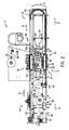
- Fig. 1
- depicts a web packaging machine.
- Fig. 2
- is a side sectional view of the machine depicted in
Fig. 1 . - Fig. 3
- is a perspective view of packaging apparatus incorporated into the machine depicted in
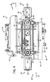
Fig. 1 , including forming and closing stations. - Fig. 4
- is a side view of the apparatus depicted in
Fig. 3 . - Fig. 5
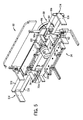
- is a perspective sectional view of the apparatus of
Fig. 4 . - Fig. 6
- is a side sectional view of the apparatus in
Fig. 5 , depicting movable forming and closing die members in open positions, respectively. - Fig. 7
- is a side sectional view of the apparatus in
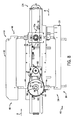
Fig. 5 , depicting movable forming and closing die members in closed positions, respectively. - Fig. 8
- is a rear view of the apparatus depicted in
Figs. 2-7 . - Fig. 9A
- is a perspective sectional view of the apparatus depicted in
Figs. 2-7 , further depicting a supporting frame. - Fig. 9B
- is a side sectional view of the apparatus depicted in
Fig. 9A . - Fig. 10
- is a perspective view of a roller conFig.d to ride on the supporting frame.
- Fig. 11
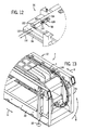
- is a perspective view of an inverted die box, form insert, and latches releasably retaining the form insert in the die box.
- Fig. 12
- is a detail view of a latch releasably retaining the form insert in the die box.
- Fig. 13
- is a partial perspective sectional view of a turret.
- Fig. 14A
- is a perspective view of a gripper clip for gripping a web of flexible packaging material.
- Fig. 14B
- is a side view of the gripper clip depicted in
Fig. 14A . - Fig. 15
- is a perspective view of movable forming and sealing die members moved into extracted positions.
- Fig. 16
- is a perspective view of movable forming and sealing die members supported on a lift.
- Fig. 17
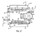
- is a sectional side view of the apparatus depicted in
Fig. 16 . - Fig. 18A
- is a sectional side view of a forming station including a lift support- ing a base in an unregistered position.
- Fig. 18B
- is a sectional side view of the lift depicted in
Fig. 18A , wherein the base is moved into a registered position. - Fig. 19
- is a sectional perspective view of the lift depicted in
Figs. 18A and 18B . - Fig. 20
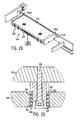
- is a sectional side view of a spring biasing a top part of the base to- wards a bottom part of the base into the registered position.
- Fig. 21
- is a sectional side view of the lift depicted in
Figs. 18A and 18B . - In the present application, certain terms have been used for brevity, clearness and understanding. No unnecessary limitations are to be implied therefrom beyond the requirement of the prior art because such terms are used for descripti ve purposes only and are intended to be broadly construed. The different structures and systems described herein may be used alone or in combination with other structures and systems. Various equivalents, alternatives, and modifications are possible within the scope of the appended claims. In the appended claims, the inventors intend to invoke interpretation under 35
USC 112, sixth paragraph in a particular claim only where the terms "means" and "for" are used in that claim. Otherwise, interpretation of the claims undersection 112, sixth paragraph is not intended. -
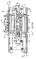
Figs. 1 and2 depict an indexingmotion packaging machine 2 that includes aweb transport conveyor 4 transporting aweb 6 of flexible packaging material along a direction of transport depicted byarrows 8 from upstream to downstream locations through a series of stations including a formingstation 10 for forming at least one pocket in theweb 6, aloading station 12 for placing food product in the pocket and aclosing station 14 for closing the pocket with anotherweb 16 of flexible packaging material. In the example depicted, themachine 2 also includes a cuttingstation 18 for separating the closed pockets into individual food containing packages. - As depicted in
Fig. 2 , the various components ofmachine 2 are mounted to and supported by aframe 20 including spaced parallel upper andlower frame members 22 andvertical frame members 24. A series of legs, e.g. 26,support machine 2 above the ground. Asupply roll 28 supplies theweb 6. Thesupply roll 28 rotates about an unwindshaft 30 to supply theweb 6 along thedirection 8. An unwind motor (not shown) drives a set of rollers and a timingpulley 9 to safely pull theweb 6 from thesupply roll 28 and along theconveyor 4 in an indexing manner and to allow a series of operations at the formingstation 10,loading station 12, closingstation 14, and cuttingstation 18 for creating a packaged product. The operation of thesupply roll 28 is similar to the operation of the supply roll arrangement depicted inU.S. Patent 5,205,110 . For brevity, further description of thesupply roll 28 and its functions are not provided herein. It will be understood by those skilled in the art that any arrangement for safely supplying a web of flexible packaging material along a web transport direction is suitable for use with the presently described embodiments. -
Figs. 3-8 depictpackaging apparatus 32 that is incorporated in themachine 2 shown inFigs. 1 and2 . Theapparatus 32 includes a formingstation 34 that includes first and second formingdie members web 6, In the embodiment shown, the first formingdie member 36 includes a die box connected to a vacuum supply for vacuum forming the pocket in theweb 6. The formingdie member 36 is movable away from and towards the formingdie member 38 between an open position (seeFig. 6 ) to allow movement of theweb 6 in thedirection 8 and a closed position (seeFig. 7 ), wherein the formingdie member 36 engages with the formingdie member 38 to sandwich theweb 6 there between and receive a vacuum to assist in formation of the noted pocket in the web. Vacuum forming of a web is described inU.S. Patent 5,205,110 . It will be understood by those skilled in the art that arrangements other than that disclosed inU.S. Patent 5,205,110 for forming a pocket in theweb 6 are suitable for use in combination with the presently described embodiments and in addition to or instead of the arrangement described inU.S. Patent 5,205,110 . In addition, although the formingstation 34 depicted and described includes a formingdie member 36 that is movable relative to a stationary formingdie member 38, those skilled in the art will recognize that the formingstation 34 could instead include forming diemembers - The
apparatus 32 also includes aclosing station 40 including first and second closing diemembers second web 16 of flexible packaging material. In the embodiment shown, theclosing die member 42 includes a die box that cooperates with a heat sealing mechanism to seal theweb 16 to theweb 6 in a manner similar to that described inU.S. Patent 5,205,110 . Closingdie member 42 is movable relative to closingdie member 44 between an open position (Fig. 6 ) to allow movement of theweb 6 in thedirection 8 and a closed position (Fig. 7 ) to close the pocket with theweb 16. Operation of closing station is more fully inU.S. Patent 5,205,110 . It will be understood by those skilled in the art that arrangements similar to that shown inU.S. Patent 5,205,110 for closing the pocket with theweb 16 are suitable for use in combination with the presently described embodiments and in addition to or instead of the arrangement described inU.S. Patent 5,205,110 . Although the embodiment describes above includes aclosing die member 42 that is movable relative to astationary closing member 44, those skilled in the art will recognize that instead the closingstation 40 could instead include closingdie members - In the embodiment shown, the forming
die member 36 and theclosing die member 42 are counterbalanced so that movement of one of these members towards its closed position assists movement of the other one of these members towards its closed position, and so that movement of one of these members towards its open position assists movement of the other one of these members towards its open position. The counterbalanced interrelationship between thedie members die member 36 is inverted with respect to theclosing die member 42, and the formingstation 34 is located below the closingstation 40 in themachine 2. In this respect, the formingstation 34 andclosing station 40 are oriented such that theweb 6 enters the formingstation 34 from one direction shown atarrow 46 and enters theclosing station 14 from another, opposite direction shown atarrow 48. Counterbalancing between the formingdie member 36 and closing diemember 42 is facilitated by alift 50 operatively connected to both the formingdie member 36 and closing diemember 42. Thelift 50 can include different mechanisms that facilitate counterbalanced, driven motion between therespective die members lift 50 moves the formingdie member 36 towards its closed position and theclosing die member 42 toward its closed position, and so that opposite movement of thelift 50 moves the formingdie member 36 towards its open position and theclosing die member 42 towards its open position. - In the embodiment shown, the
respective die members lift 50 is disposed between the formingstation 34 and theclosing station 40. Thelift 50 is located vertically higher than the formingstation 34 and vertically lower than the closingstation 40. In operation, thelift 50 rotates in a first direction shown inFig. 7 atarrow 52 to move therespective die members lift 50 rotates in a second, opposite direction show inFig. 6 atarrow 54 to move therespective die members arrows 53 and towards their respective open positions. - Movement of
lift 50 facilitates counterbalanced motion between therespective die members lift 50 includes a pair ofdrive arms Figs. 5 and4 , respectively). With reference toFigs. 6 and7 showing a sectional view of theapparatus 32 and depicting only drivearm 56a, eachdrive arm pivot axis 58 and has a first end 60 operatively connected to theclosing die member 42 and a second,opposite end 62 operatively connected to the formingdie member 36. As shown inFig. 8 , thelift 50 also includes adrive wheel 64 operatively connected to thedrive arms drive wheel 64 is attached to arotatable shaft 66, which extends along theaxis 58. Thedrive arms shaft 66 and thus rotate concentrically and along with rotation of thedrive wheel 64. Rotation of thedrive wheel 64 thus causes rotation of thedrive arms axis 58 and, as described further below, causes movement of theclosing die box 42 and the formingdie box 36 into and out of the respective open and closed positions. - In the embodiment shown, the
lift 50 also includes a follower wheel 68 (seeFig. 4 ) that is operatively connected to thedrive wheel 64 so that rotation of thedrive wheel 64 causes rotation of thefollower wheel 68. Connection of thefollower wheel 68 to thedrive wheel 64 can be accomplished in different ways. In the example shown the connection is accomplished by abelt 70 that operatively connects thefollower wheel 68 to therotatable shaft 66, which in turn is connected to thedrive wheel 68. - A pair of
follower arms Figs. 5 and4 , respectively) are operatively connected to thefollower wheel 68 so that rotation of thefollower wheel 68 causes rotation of thefollower arms follower arms follower wheel 68 to arotatable shaft 74 to which thefollower arms follower arms follower wheel 68. With reference toFigs. 6 and7 showing sectional views of theapparatus 32 and depictingonly follower arm 72a, eachfollower arm first end 76 operatively connected to the movable firstclosing die member 42 and a second,opposite end 78 operatively connected to the formingdie member 36. As explained further below, rotation of thefollower arms closing die member 42 and the formingdie member 36 into and out of the open and closed positions. - A
servomotor 80 is connected to thedrive wheel 64 by a belt 81 (seeFig. 8 ) and operatively drives thedrive wheel 64 into rotation in a back and forth direction shown atarrows rotatable shaft 66 aboutaxis 58, which in turn causes drivearms Figs. 6 and7 . Rotation of thedrive wheel 64 is translated tofollower wheel 68 viabelt 70 and thus causes rotation offollower wheel 68 in the same timing and orientation. Rotation offollower wheel 68 causes rotation offollower arms Figs. 6 and7 . - Referring now to
Figs. 6 and7 , respectively, pivoting movement of thedrive arms follower arms die members drive arms closing die member 42 and the second ends 62 of thedrive arms die member 36. Both of the guide tracks 84, 86 include first andsecond rails Bearings 92 are operatively connected to each of the first ends 60 of thedrive arms rails guide track 84.Bearings 94 are operatively connected to the second ends 62 of thedrive arms rails guide track 86. -
Follower arms bearings rails follower arms drive arms servo motor 80 thus causes rotation of both thedrive arms follower arms movable die members Figs. 6 and7 , respectively. Specifically, rotation of thedrive arms bearings 94 to ride along rails 88, 90 and push the formingdie member 36 and closing diemember 42 into and out of the open and closed positions. In the same way, rotation of thefollower arms bearings die member 36 and closing diemember 42 into and out of the open and closed positions. - In the embodiment shown, the forming
die member 36 is oriented upside-down in thepackaging apparatus 32, such that the formingdie member 36 is inverted with respect to theclosing die member 42. Referring toFigs. 11 and12 , aform insert 96 is releasably retained with the rest of formingdie member 36 by a plurality oflatches 98.Latches 98 can include different latching configurations to provide a releasable connection of theform insert 96 to the rest of formingdie member 36. In the example shown, latch 98 includes alocking pin 100 releasably engaged in apull tab 102 defining arecess 104 that includes aslot 106 andkey hole 108. Referring toFig. 12 , theform insert 96 is shown in its attached position. Release of theform insert 96 is accomplished by pullingtab 102 in the direction ofarrow 110 until the head ofpin 100 is aligned withkey hole 108.Key hole 108 is sized slightly larger than the head ofpin 100 and thus thepin 100 is allowed by the force of gravity to pass through thekey hole 108. Attachment of theform insert 96 is accomplished by following the above described procedure in reverse. Thepin 100 is inserted into thekey hole 108 and thetab 102 is slid inward in the direction ofarrow 112 until the pin is aligned inslot 106, which is sized slightly smaller than the head ofpin 100, thus retaining theform insert 96 in position. The above steps are repeated for eachlatch 98 in the plurality to selectively attach or detach theform insert 96 to the rest of formingdie member 36. - Embodiments of a
packaging apparatus 32 are thus depicted and described that includes a movable forming die member and movable closing die member that are counterbalanced so that movement of one of the die members towards its closed position assists movement of the other die member towards its closed position. In the example shown, the weight of theclosing die member 42 acts upon thelift 50 and thereby assists in rotation of thedrive arms follower arms die member 36. Conversely, the weight of formingdie member 36 acts upon thelift 50 and thereby assists and causes rotation of thedrive arms follower arms closing die member 42. - In the example shown, the
lift 50 is operatively connected to and counterbalances the formingdie member 36 and theclosing die member 42. Movement of thelift 50 moves the formingdie member 36 towards its closed position and theclosing die member 42 towards its closed position. Opposite movement of thelift 50 moves the formingdie member 36 towards its open position and theclosing die member 42 towards its open position. - Again, although the present embodiment includes the above-described configuration for generating rotational motion of the lift, and counterbalanced motion of the forming station and sealing station, various other alternative embodiments could be employed in combination with or in addition to the lift shown and described, forming station embodiment, and closing station embodiments described. For example, the lift could also or alternatively include a wheel disposed laterally between adjacent movable die members (36a, 42a) and connected thereto by, for example a rack and pinion connection. Rotation of the rotational member in one direction would move one of the members up and the other member down, and vice versa. In a similar way, such an arrangement would achieve substantially similar function and similar results.
- During operation, the
web 6 is indexingly moved through themachine 2 by theconveyor 4 along thedirection 8, and through the formingstation 10,loading station 12, closingstation 14, and cuttingstation 18, in a similar manner as that described inU.S. Patent 5,205,110 . As theweb 6 enters the formingstation 10 in direction ofarrow 46 for formation of the noted pocket, a downstream portion of theweb 6 simultaneously enters theclosing station 16 atarrow 48 for closing with theweb 6 pocket with theweb 16. The respective indexed progressions occur in a synchronized manner such that formation at the formingstation 10 occurs simultaneously with closing at theclosing station 14 according to the above-described driven, counterbalanced movement of therespective die members Figs. 6 and7 . - Referring to
Figs. 9a ,9b and10 , theapparatus 32 is laterally movable with respect to themachine 2 along theweb transport direction 8. Specifically, thepackaging apparatus 32 includes a frame 114 (seeFig. 3 for perspective view) that supports the formingstation 10 andclosing station 14 so that thestations packaging machine 2 in a direction substantially parallel to the direction of travel of theweb 8. Theframe 114 can include different arrangements, and in the embodiment shown includes a series ofrails 116 upon which the formingstation 34 andclosing station 40 are supported. A plurality of rollers 118 (shown in detail inFig. 10 ) are attached to theapparatus 32 and ride on therails 116 of theframe 114 and thus movably support the formingstation 34 andclosing station 40 at different positions in themachine 2 laterally along thedirection 8. In the embodiment shown, therollers 118 include awheel 120 rotatably journalled about anaxle 122 that is supported onhousing 124 attached to theapparatus 32. Lateral movement of theframe 114 allows the apparatus to properly function with form inserts 96 having different index lengths. Specifically, theapparatus 32 can be moved laterally along thedirection 8 to a preselected position chosen based upon the particular index length of a chosenform insert 96, and so that the distance from a selected point in the formingstation 34 to a selected point in theclosing station 40 remains divisible by a perfect number regardless of the particular index length of theform insert 96 installed in the formingstation 34. This allows for indexed motion and simultaneous operation of the formingstation 10 andclosing station 14 with different form inserts having different index lengths. -
Figs. 13 ,14a and 14b depict a clamping arrangement for gripping and carrying theweb 6 in theweb transport direction 8. The clamping arrangement includes a plurality ofclamps 128 configured substantially in accordance with the arrangement described inU.S. Patent 4,915,283 . A pair of aligned opposingdrive chains 126 are configured to travel about a set predetermined path within thepackaging machine 2. A plurality ofclamps 128 are fastened to thechains 126 at fixed distances from one another such that theclamps 128 on onechain 126 are directly aligned with and face theclamps 128 on the opposingchain 126. Eachclamp 128 includes first andsecond jaw members U.S. Patent 4,915,283 .Teeth 134 are formed on thejaw members pitch line 133 of therespective drive chains 126. This configuration allows for travel of theweb 6 around turret 136 on thepackaging machine 2 to reverse movement of thetransport conveyor 4 to allow for movement of theweb 6 in the opposite directions ofarrows web 6 and pockets formed therein during movement about turret 136. -
Figs. 15 - 21 depict further embodiments of thepackaging apparatus 32. As shown inFigs. 16 and17 , abase 138 supports movement of the formingdie member 36 between the noted first, open position in which the formingdie member 36 is moved away from theweb 6 of packaging material and the second, closed position in which the formingdie member 36 engages theweb 6 and assists in forming at least one pocket in theweb 6. In the same way, abase 138 supports movement of theclosing die member 44 between the noted open position in which theclosing die member 42 is moved away from theweb 6 and the closed position in which theclosing die member 42 engages theweb 6 and assists in closing theweb 6 with theweb 16. As shown inFig. 15 , each of the formingdie member 36 and closing diemember 42 are also movable into third, extracted positions shown inFig. 15 along a direction shown byarrow 140, transverse to the movement of thedie members Figs. 6 and7 ). Similar to the arrangements described inU.S. Patent Application 7,340,871 , formingdie member 36 and closing diemember 42 are typically moved into the noted extracted positions to enable tooling change or repair. - As shown in
Fig. 15 , aguide track assembly 170 extends laterally of thebase 138 and supports theclosing die member 42 and the formingdie member 36 during movement into the noted third positions.Figs. 3 and4 show perspective views of theassembly 170 in a retracted position, pivoted inwardly against the exterior ofmachine 2.Assembly 170 includesrails 172 for supporting movement of thebase 138 and closing diemember 44 into the noted third, extracted position shown inFig. 15 . In addition, rails 174 engage with the formingdie member 36 to support the formingdie member 36 against the force of gravity in the depicted inverted position. In the example shown, therails 174 are spaced apart and includechannels 176 sized to slideably mate with the outer edges ofbase 138, thus facilitating movement into the noted third, extracted position. - The
apparatus 32 can also be configured to facilitate registration and unregistration of the formingdie member 36 into and out of the formingstation 10 and to facilitate registration and unregistration of theclosing die member 42 into and out of theclosing station 14, when movement into the respective extracted positions is desired. For brevity, the following description and related Figs. discusses the structures for assisting registration and unregistration of theclosing die member 42. However it should be recognized that the same or similar structures are also provided for the formingdie member 36, which in the embodiment shown would be inverted with respect to that shown for theclosing die member 36. - Referring to
Fig. 18-21 , thebase 138 and closing diemember 42 are normally biased into a registered position shown inFig. 18A , wherein theclosing die member 42 is prevented from moving out of theclosing station 14 into the extracted position shown inFig. 15 . To enable tooling change, alift 144 is selectively operable to move the base 138 against the bias into an unregistered position shown inFig. 18B , wherein theclosing die member 2 is free to move outwardly into the extracted position. Thebase 138 and lift 144 can include various structural connections for accomplishing the above noted functionality. In the embodiment shown, thebase 138 includes top andbottom parts Fig. 18A . Actuation of thelift 144 moves thebottom part 148 towards thetop part 146 into the unregistered position shown inFig. 18B . In the example shown, the top andbottom parts springs 152 into the noted unregistered position. However other suitable support structures could be employed instead of plates for performing the noted function. -
Fig. 20 depicts an example of aspring 152 for providing the noted bias. Abolt 154 is connected to thetop part 146. Thebolt 154 is also connected to a bushing 156 having flange surfaces 158.Spring 152 applies outwardly compressive force on the flange surfaces 158 of the bushing 156 and on aninner flange surface 160 on thebottom part 148 ofbase 138. By pushing the flange surfaces 158, 160 apart, thespring 152 biases the bottom apart 148 away from thetop part 146 to move the first movable closing diemember 42 upward into the unregistered position. - Referring to
Figs. 18A, 18B and19 , opposingside rails inner channel 164 are provided on opposing sides of the top andbottom parts bottom part 148 of thebase 138 and at the other (upper) end to the first movable closing diemember 42. Thetop part 146 of thebase 138 is fixed to theapparatus 32. The side rails 162a, 162b guide movement of thebottom part 148 to move the movable closing diemember 42 between the noted registered and unregistered positions. When thebottom part 148 of thebase 138 is in the registered position, a packagingmachine frame element 151 prevents movement of the movable closing diemember 42 into the extracted position shown inFig. 15 . When thebottom part 148 of thebase 138 is in the unregistered position, the packagemachine frame element 151 does not prevent movement of the moveable closing diemember 42 into the extracted position shown inFig. 15 . In the embodiment shown, the packagingmachine frame element 151 includes a side rail on themachine 2. - In the embodiment shown, the
lift 144 includes abladder 150 disposed between the upper andlower parts bladder 150 inflates and therefore expands thebladder 150. The outer surfaces of thebladder 150 thus push thebottom part 148 away from thetop part 146 and into the registered position shown inFig. 18A . Evacuating pressurized air from thebladder 150 deflates and therefore contracts thebladder 150, which releases pressure from theparts bottom part 148 to be biased into the unregistered position. Although thelift 144 in the present embodiment includes abladder 150, it will be recognized that the lift could include different mechanisms for moving thebase 138 and associated diemember -
Packaging apparatus 32 is thus provided that includes a plurality ofsprings 152 biasing thebottom part 148 of the base 138 into the noted unregistered position, wherein the lift includes abladder 150 that inflates to move thebottom part 148 of the base 138 into the registered position, and deflates to allow thebottom part 148 to be biased into the unregistered position. In this manner, the movable firstclosing die member 42 is movable into the extracted position shown inFig. 15 , while theweb 6 remains uncut and in place. This same principle also applies to the movable first formingdie member 36, as discussed above. - Alternative arrangements for facilitating registration and unregistration of the forming
die member 36 and closing diemember 42 are contemplated. For example, instead of providing thelift 144 to move therespective die members apparatus 32 to clear theframe element 151,apparatus 32 could include a lift mechanism that moves theframe element 151 while thedie members die members die members frame element 151 to achieve the requisite clearance to allow movement into the extracted positions. The effect of these embodiments is thus to allow for registration and unregistration of the die members to prevent and allow movement into the extracted positions, respectively.
Claims (15)
- A packaging apparatus for an indexing-motion packaging machine,
the machine comprising a web transport conveyor transporting a first web of flexible packaging material along a direction of transport from upstream to downstream locations through a series of stations including (A) a forming station for forming at least one pocket in the first web, (B) a loading station for placing food product in the at least one pocket, and (C) a closing station for closing the pocket with a second web of packaging material characterized in that
the packaging apparatus comprises
a forming station comprising first and second forming die members, at least one of the first and second forming die members being movable between first, open position relative to the other one of the first and second forming die members in which position the movable forming die member is moved away from the first web, and a second, closed position relative to the other one of the first and second forming die members in which position the movable forming die member engages the first web and assists in forming the first web into the pocket, wherein the movable forming die member is movable into a third, extracted position along a direction transverse to the direction of movement of the movable forming die member between the first, open and second, closed positions and transverse to the direction of transport of the first web, the movable forming die member being moved to said third, extracted position to enable tooling change, and
a lift that is selectively operable to register and unregister the movable forming die member in the packaging apparatus, wherein, when registered, the movable forming die member is prevented from moving into the third, extracted position and wherein, when unregistered, the movable forming die member is free to move into the third, extracted position. - The packaging apparatus according to claim 1,
wherein the lift is configured to move the movable forming die member between a registered position and an unregistered position,
wherein, preferably, it further comprises a base supporting movement of the movable forming die member between the first, open position and the second, closed position,
wherein, further preferably, it further comprises a guide track assembly extending laterally of the base and supporting the movable forming die member during movement from the unregistered position into the third, extracted position. - The packaging apparatus according to claim 2,
wherein the base comprises top and bottom parts that are biased together to position the movable forming die member into the registered position and wherein actuation of the lift moves the bottom part away from the top part to move the base and the movable forming die member into the unregistered position. - The packaging apparatus according to claim 3,
wherein the lift comprises a bladder that deflates to allow the bottom part of the base to move into the registered position and inflates to move the bottom part into the unregistered position, and/or
wherein the lift comprises at least one spring biasing the bottom part towards the top part into the registered position, and/or
wherein the top and bottom parts comprise plates, and/or
comprising at least one side rail supporting movement of the bottom part - The packaging apparatus according to claim 4,
wherein the lift comprises at least one spring biasing the bottom part towards the top part to thereby move the movable forming die member into the registered position and the lift comprises a bladder that inflates to move the bottom part of the base to thereby move the movable forming die member into the unregistered position and deflates to allow the bottom part to be biased into the registered position. - The packaging apparatus according to claim 4 or 5,
comprising means for actuating the lift to move the movable forming die member into and out of the registered and unregistered positions, and/or
comprising a packaging machine frame element preventing movement of the movable forming die member into the third, extracted position when the movable forming die member is in the registered position. - The packaging apparatus according to claim 2 and optionally any other one of the preceding claims,
wherein the first web remains uncut and in place during movement of the movable forming die member into the third, extracted position. - A packaging apparatus for an indexing-motion packaging machine,
the machine comprising a web transport conveyor transporting a first web of flexible packaging material along a direction of transport from upstream to downstream locations through a series of stations including (A) a forming station for forming at least one pocket in the first web, (B) a loading station for placing food product in the at least one pocket, and (C) a closing station for closing the pocket with an second web of packaging material,
optionally according to any one of the preceding claims,
characterized in that
the packaging apparatus comprises
a closing station comprising first and second closing die members, at least one of the first and second closing die members being movable between first, open position relative to the other one of the first and second closing die members in which position the movable closing die member is moved away from the first web and a second, closed position relative to the other one of the first and second closing die members in which position the movable closing die member engages the first web and assists in closing the pocket,
wherein the movable closing die member is movable into a third, extracted position along a direction transverse to the direction of movement of the movable closing die member between the first, open and second, closed positions and transverse to the direction of transport of the first web, the movable closing die member being moved to said third, extracted position to enable tooling change, and
a lift that is selectively operable to register and unregister the movable forming die member in the packaging apparatus, wherein, when registered, the movable closing die member is prevented from moving into the third, extracted position and wherein when unregistered, the movable closing die member is free to move into the third, extracted position. - The packaging apparatus according to 8,
wherein the lift is configured to move the movable closing die member between a registered position and an unregistered position,
wherein, preferably, it further comprises a base supporting movement of the movable closing die member between the first, open position and the second, closed position,
wherein, further preferably, it further comprises a guide track assembly extending laterally of the base and supporting the movable closing die member during movement from the unregistered position into the third, extracted position. - The packaging apparatus according to claim 9,
wherein the base comprises top and bottom parts that are biased together to position the movable closing die member into the registered position and wherein actuation of the lift moves the bottom part away from the top part to move the base and the movable closing die member into the unregistered position. - The packaging apparatus according to claim 10,
wherein the lift comprises a bladder that deflates to allow the bottom part of the base to move into the registered position and inflates to move the bottom part into the unregistered position, and/or
wherein the lift comprises at least one spring biasing the bottom part towards the top part into the registered position, and/or
wherein the top and bottom parts comprise plates, and/or
comprising at least one side rail supporting movement of the bottom part - The packaging apparatus according to claim 11,
wherein the lift comprises at least one spring biasing the bottom part towards the top part to thereby move the movable closing die member into the registered position and the lift comprises a bladder that inflates to move the bottom part of the base to thereby move the movable closing die member into the unregistered position and deflates to allow the bottom part to be biased into the registered position. - The packaging apparatus according to claim 11 or 12,
comprising means for actuating the lift to move the movable forming die member into and out of the registered and unregistered positions, and/or
comprising a packaging machine frame element preventing movement of the movable closing die member into the third, extracted position when the movable forming die member is in the registered position. - The packaging apparatus according to claim 9 and optionally any other one of the preceding claims,
wherein the first web remains uncut and in place during movement of the movable closing die member into the third, extracted position. - The packaging apparatus according to the claims 1 and 8 and optionally any other one of the preceding claims,
wherein the lift is configured for selectively moving at least one of the movable closing die member and the movable forming die member into an unregistered position wherein the at least one of the movable forming die member and movable closing die member is free to move into its third, extracted position.
Applications Claiming Priority (2)
| Application Number | Priority Date | Filing Date | Title |
|---|---|---|---|
| US17921609P | 2009-05-18 | 2009-05-18 | |
| US12/605,171 US8499536B2 (en) | 2009-05-18 | 2009-10-23 | Apparatuses and methods for assisted tooling extraction |
Publications (3)
| Publication Number | Publication Date |
|---|---|
| EP2253544A2 true EP2253544A2 (en) | 2010-11-24 |
| EP2253544A3 EP2253544A3 (en) | 2011-03-02 |
| EP2253544B1 EP2253544B1 (en) | 2012-03-14 |
Family
ID=42629523
Family Applications (1)
| Application Number | Title | Priority Date | Filing Date |
|---|---|---|---|
| EP10005160A Revoked EP2253544B1 (en) | 2009-05-18 | 2010-05-18 | Packaging apparatus with assisted tooling extraction |
Country Status (6)
| Country | Link |
|---|---|
| US (1) | US8499536B2 (en) |
| EP (1) | EP2253544B1 (en) |
| JP (1) | JP2010265039A (en) |
| AT (1) | ATE549248T1 (en) |
| CA (1) | CA2701285A1 (en) |
| ES (1) | ES2382989T3 (en) |
Cited By (3)
| Publication number | Priority date | Publication date | Assignee | Title |
|---|---|---|---|---|
| EP2505504A2 (en) | 2011-03-30 | 2012-10-03 | Alkar-RapidPak-MP Equipment, Inc. | Packaging apparatus |
| US8820037B2 (en) | 2010-07-29 | 2014-09-02 | Multivac Sepp Haggenmueller Gmbh & Co. Kg | Thermoforming packaging machine and a method for filling packaging troughs with products |
| EP2873623A1 (en) * | 2013-11-15 | 2015-05-20 | Multivac Sepp Haggenmüller GmbH & Co. KG | Deep draw packaging machine with adjustable chain guide |
Families Citing this family (17)
| Publication number | Priority date | Publication date | Assignee | Title |
|---|---|---|---|---|
| DE102010009536A1 (en) * | 2010-02-26 | 2011-09-01 | Cfs Germany Gmbh | Method for changing the upper and lower tool of a packaging machine |
| DE102011101051A1 (en) * | 2011-05-10 | 2012-11-15 | Multivac Sepp Haggenmüller Gmbh & Co. Kg | Tool changer |
| DE102012003830A1 (en) * | 2012-02-29 | 2013-08-29 | Gea Cfs Germany Gmbh | Packaging machine with a replaceable tool |
| EP2740677A1 (en) * | 2012-12-10 | 2014-06-11 | Multivac Sepp Haggenmüller GmbH & Co. KG | Transport device for deep draw packaging machine |
| ITMI20132079A1 (en) * | 2013-12-13 | 2015-06-14 | Antonio Rossini | PACKAGING DEVICE. |
| US10472106B2 (en) * | 2014-07-04 | 2019-11-12 | Sarong S.P.A. | Machine and method for making capsules for beverages |
| US20160325868A1 (en) * | 2015-05-08 | 2016-11-10 | Alkar-Rapidpak, Inc. | Contour cutting station for web packaging machine |
| US10625892B2 (en) * | 2015-10-14 | 2020-04-21 | Alkar-Rapidpak, Inc. | Web packaging machines with variable depth forming |
| CN105564751A (en) * | 2016-01-17 | 2016-05-11 | 陈吉美 | Food processing device |
| US20170313457A1 (en) | 2016-04-28 | 2017-11-02 | Alkar-Rapidpak, Inc. | Clamping devices for clamping die members onto web packaging machines |
| US10507626B2 (en) | 2016-05-16 | 2019-12-17 | Alkar-Rapidpak, Inc. | Bladder devices for moving components of web packaging machines |
| US10954014B2 (en) | 2016-06-09 | 2021-03-23 | Alkar-Rapidpak, Inc. | Lifting assemblies for assisting movement of die boxes on web packaging machines |
| US10875670B2 (en) | 2016-11-04 | 2020-12-29 | Alkar-Rapidpak, Inc. | Web-packaging machines with multiple sealing stations |
| CN108528839B (en) * | 2018-04-26 | 2023-08-29 | 佛山道斯水溶包装技术有限公司 | Circulation type vacuumizing structure and packaging machine |
| DE102019210728A1 (en) * | 2019-07-19 | 2021-01-21 | Multivac Sepp Haggenmüller Se & Co. Kg | Workstation for a packaging machine |
| IT202100017840A1 (en) * | 2021-09-03 | 2023-03-03 | Erco Service S R L | PAPER-PUTTING APPARATUS AND RELATED DEVICE AND METHOD OF FEEDING |
| DE102024124007A1 (en) * | 2024-08-22 | 2026-02-26 | Weber Food Technology Se & Co. Kg | Adjustment module for optional insertion into a tool of a workstation of a packaging machine |
Citations (3)
| Publication number | Priority date | Publication date | Assignee | Title |
|---|---|---|---|---|
| US4915283A (en) | 1988-10-06 | 1990-04-10 | Curwood, Inc. | Clamping arrangement for gripping and carrying web material |
| US5205110A (en) | 1990-12-12 | 1993-04-27 | Buchko Raymond G | Servo motor operated indexing motion packaging machine and method |
| US7340871B1 (en) | 2006-03-31 | 2008-03-11 | Alkar-Rapidpak, Inc. | Web packaging system with ergonomic tooling change |
Family Cites Families (41)
| Publication number | Priority date | Publication date | Assignee | Title |
|---|---|---|---|---|
| US3230869A (en) | 1962-06-19 | 1966-01-25 | Wilkins & Mitchell Ltd | Raising and clamping means for sliding bolsters |
| JPS4936998B1 (en) | 1966-02-09 | 1974-10-04 | ||
| DE2052551A1 (en) | 1970-10-27 | 1972-06-22 | Fa. Ganzhorn u. Stirn, 7170 Schwäbisch Hall | Filling machine with molding device |
| DE2235280A1 (en) | 1972-07-19 | 1974-01-31 | Applic Plastique Mec Elec | CLAMPING AND FEEDING DEVICE FOR PLASTIC FILM TAPES GUIDED IN PLASTIC FORMING MACHINES |
| FR2337622A1 (en) | 1976-01-09 | 1977-08-05 | Anvar | PROCESS FOR MOLDING OBJECTS IN AGGLOMERATED PARTICLES AND DEVICE FOR IMPLEMENTING THIS PROCESS |
| US4137784A (en) | 1977-11-14 | 1979-02-06 | Industrial Device Corporation | Electromechanical equivalent of fluid powered cylinder |
| JPS58119926U (en) * | 1982-02-04 | 1983-08-16 | 相生精機株式会社 | Mold changing device for processing machines that use molds |
| US4529371A (en) | 1984-06-06 | 1985-07-16 | Cincinnati Milacron Inc. | Mold changer for a press preferably an injection molding machine |
| US4894977A (en) | 1986-01-29 | 1990-01-23 | Josef Uhlmann Maschinenfabrik Gbmh & Co. Kg | Method and device for the length rectification of a foil strip of a material which shrinks during cooling in machines for the production and separation of packages |
| US4773839A (en) | 1987-02-05 | 1988-09-27 | Amoco Corporation | Quick-change thermoformer |
| GB2215705A (en) | 1988-03-16 | 1989-09-27 | Nomix Mfg Co Ltd | Manufacturing containers |
| US4897985A (en) | 1988-10-06 | 1990-02-06 | Curwood, Inc. | Continuous motion package forming machine |
| FR2648432B1 (en) | 1989-06-16 | 1991-09-13 | Mecaplastic | DEVICE AND INSTALLATION FOR THE PACKAGING OF ANY PRODUCTS, FOR EXAMPLE OF FOOD PRODUCTS, IN TRAYS CLOSED BY A WELDED CLOSURE FILM |
| DE9010832U1 (en) | 1990-07-20 | 1990-09-27 | Läcovac-Vakuumtechnik GmbH, 4516 Bissendorf | Device for producing plastic packaging |
| US5170611A (en) * | 1990-12-12 | 1992-12-15 | Rapidpak, Inc. | Web supply mechanism for an indexing motion packaging machine |
| DE9113290U1 (en) * | 1991-10-25 | 1991-12-19 | Krämer + Grebe GmbH & Co KG Maschinenfabrik, 3560 Biedenkopf | Device for producing a packaging |
| IT1262305B (en) | 1993-02-23 | 1996-06-19 | PROCESS AND PLANT FOR PACKAGING FLUID OR SEMI-FLUID PRODUCTS IN THERMOFORMABLE SYNTHETIC RESIN CONTAINERS. | |
| US5443150A (en) | 1993-09-23 | 1995-08-22 | Rapidpak, Inc. | Apparatus for advancing preformed containers |
| US5785270A (en) | 1995-09-20 | 1998-07-28 | Rapidpak, Inc. | Combined support, adjustment and braking mechanism for use in unwinding a roll of web material |
| US6085490A (en) | 1998-02-11 | 2000-07-11 | Rapidpak, Inc. | Forming web registration control system |
| DE19824589A1 (en) | 1998-06-02 | 1999-12-09 | Kraemer & Grebe Kg | Sealing tool and method for sealing packaging |
| DE10108163A1 (en) | 2001-02-20 | 2002-08-29 | Ps Systempack Gmbh | Device on a thermoforming packaging machine |
| US6604452B2 (en) | 2001-05-08 | 2003-08-12 | Alkar-Rapidpak, Inc. | Food processor with circulation system and method |
| ITBO20010650A1 (en) | 2001-10-26 | 2003-04-26 | Ima Spa | METHOD AND MACHINE FOR THE CREATION OF BLISTER PACKS |
| US6523462B1 (en) | 2002-06-27 | 2003-02-25 | Alkar-Rapidpak, Inc. | Aligned food processing system |
| US6843043B2 (en) | 2002-09-13 | 2005-01-18 | Alkar Rapidpak, Inc. | Web packaging pasteurization system |
| US6976347B2 (en) | 2002-09-13 | 2005-12-20 | Alkar-Rapidpak, Inc. | Surface pasteurization method |
| US7325486B1 (en) | 2002-12-04 | 2008-02-05 | Alkar-Rapidpak, Inc. | Food processing apparatus and method |
| DE10302723A1 (en) | 2003-01-23 | 2004-08-05 | Iwk Verpackungstechnik Gmbh | Method for controlling a blister packaging machine |
| KR101309950B1 (en) * | 2003-04-01 | 2013-09-17 | 어댑트시스, 엘티디. | Plastic embossed carrier tape apparatus and process |
| US6843038B1 (en) | 2003-08-21 | 2005-01-18 | Illinois Tool Works Inc. | Method and apparatus for controlling zipper tension in packaging equipment |
| US7083509B2 (en) | 2003-10-10 | 2006-08-01 | Alkar-Rapid Pak, Inc. | High capacity food processing system |
| US7607973B1 (en) | 2004-09-22 | 2009-10-27 | Alkar-Rapidpak, Inc. | High yield bacon comb |
| DE102004051923B4 (en) | 2004-10-25 | 2007-12-06 | Variovac Ps Systempack Gmbh | Sealing station on a packaging machine having one or more individually manageable sealing cassettes |
| DE202004016538U1 (en) | 2004-10-25 | 2005-02-10 | Variovac Ps Systempack Gmbh | Sealing station for packing machines has upper and lower sections which can be moved together to seal articles between sheets, cassette being mounted in upper section containing heated plate which can be raised and lowered |
| US7490448B1 (en) | 2007-03-09 | 2009-02-17 | Alkar-Rapidpak, Inc. | Form-fill-seal web packaging system with sealing station |
| US7703265B2 (en) | 2007-10-23 | 2010-04-27 | Alkar-Rapidpak, Inc. | Web packaging system with ergonomic forming plug change |
| US7976885B2 (en) | 2007-10-23 | 2011-07-12 | Alkar-Rapidpak-Mp Equipment, Inc. | Anti-microbial injection for web packaging pasteurization system |
| DE102007062983A1 (en) | 2007-12-21 | 2009-06-25 | Ulma Packaging Gmbh | packaging machine |
| DE102008019628A1 (en) | 2008-04-18 | 2009-11-05 | Multivac Sepp Haggenmüller Gmbh & Co. Kg | packaging machine |
| DE102008019626A1 (en) | 2008-04-18 | 2009-10-29 | Multivac Sepp Haggenmüller Gmbh & Co. Kg | Workstation of a packaging machine with a lifting device |
-
2009
- 2009-10-23 US US12/605,171 patent/US8499536B2/en active Active
-
2010
- 2010-04-22 CA CA2701285A patent/CA2701285A1/en not_active Abandoned
- 2010-05-11 JP JP2010109400A patent/JP2010265039A/en active Pending
- 2010-05-18 AT AT10005160T patent/ATE549248T1/en active
- 2010-05-18 ES ES10005160T patent/ES2382989T3/en active Active
- 2010-05-18 EP EP10005160A patent/EP2253544B1/en not_active Revoked
Patent Citations (4)
| Publication number | Priority date | Publication date | Assignee | Title |
|---|---|---|---|---|
| US4915283A (en) | 1988-10-06 | 1990-04-10 | Curwood, Inc. | Clamping arrangement for gripping and carrying web material |
| US5205110A (en) | 1990-12-12 | 1993-04-27 | Buchko Raymond G | Servo motor operated indexing motion packaging machine and method |
| US5205110C1 (en) | 1990-12-12 | 2001-05-15 | Dec Int | Servo motor operated indexing motion packaging machine and method |
| US7340871B1 (en) | 2006-03-31 | 2008-03-11 | Alkar-Rapidpak, Inc. | Web packaging system with ergonomic tooling change |
Cited By (5)
| Publication number | Priority date | Publication date | Assignee | Title |
|---|---|---|---|---|
| US8820037B2 (en) | 2010-07-29 | 2014-09-02 | Multivac Sepp Haggenmueller Gmbh & Co. Kg | Thermoforming packaging machine and a method for filling packaging troughs with products |
| EP2505504A2 (en) | 2011-03-30 | 2012-10-03 | Alkar-RapidPak-MP Equipment, Inc. | Packaging apparatus |
| EP2505504A3 (en) * | 2011-03-30 | 2013-04-17 | Alkar-RapidPak-MP Equipment, Inc. | Packaging apparatus |
| US9156573B2 (en) | 2011-03-30 | 2015-10-13 | Alkar-Rapidpak, Inc. | Packaging apparatuses and methods |
| EP2873623A1 (en) * | 2013-11-15 | 2015-05-20 | Multivac Sepp Haggenmüller GmbH & Co. KG | Deep draw packaging machine with adjustable chain guide |
Also Published As
| Publication number | Publication date |
|---|---|
| US20100287889A1 (en) | 2010-11-18 |
| JP2010265039A (en) | 2010-11-25 |
| EP2253544A3 (en) | 2011-03-02 |
| ATE549248T1 (en) | 2012-03-15 |
| ES2382989T3 (en) | 2012-06-15 |
| US8499536B2 (en) | 2013-08-06 |
| CA2701285A1 (en) | 2010-11-18 |
| EP2253544B1 (en) | 2012-03-14 |
Similar Documents
| Publication | Publication Date | Title |
|---|---|---|
| EP2253544B1 (en) | Packaging apparatus with assisted tooling extraction | |
| EP2253543B2 (en) | Indexing-motion packaging apparatus | |
| US8181432B2 (en) | Web packaging system with ergonomic forming plug change | |
| US7607279B2 (en) | Web packaging system with ergonomic tooling change | |
| US8240353B2 (en) | Gripper assembly for tray sealing machine | |
| US5058364A (en) | Packaging machine adapted to convert pouches from edgewise advance to broadwise advance | |
| EP3090953B1 (en) | Cutting station for a web packaging machine | |
| US8720667B2 (en) | Product bag unloading apparatus | |
| US9156573B2 (en) | Packaging apparatuses and methods | |
| CN111136185B (en) | Photovoltaic module frame long side transfer device matched with punching machine and riveting machine | |
| EP3625131B1 (en) | Wrapping machine | |
| US11331902B2 (en) | Blowing means unit and hot foil stamping and die-cutting device | |
| JP6647661B2 (en) | Medium filling bag folding device | |
| CN216032833U (en) | Satisfy aluminium membrane welding production line of requirement of aerifing | |
| JP2019142079A (en) | Mold conveyance structure | |
| EP2316762B1 (en) | Apparatus and method for handling groups of objects in a palletising plant | |
| JP4607653B2 (en) | Spout mounting device | |
| JP2023160634A (en) | Container processing system | |
| CN205891395U (en) | Device is broken to automatic mark that pastes of bag body | |
| CN111038767A (en) | Bagged material boxing mechanism | |
| JP2003341627A (en) | End seal apparatus for horizontal bag making and filling machine |
Legal Events
| Date | Code | Title | Description |
|---|---|---|---|
| PUAI | Public reference made under article 153(3) epc to a published international application that has entered the european phase |
Free format text: ORIGINAL CODE: 0009012 |
|
| AK | Designated contracting states |
Kind code of ref document: A2 Designated state(s): AL AT BE BG CH CY CZ DE DK EE ES FI FR GB GR HR HU IE IS IT LI LT LU LV MC MK MT NL NO PL PT RO SE SI SK SM TR |
|
| AX | Request for extension of the european patent |
Extension state: BA ME RS |
|
| PUAL | Search report despatched |
Free format text: ORIGINAL CODE: 0009013 |
|
| AK | Designated contracting states |
Kind code of ref document: A3 Designated state(s): AL AT BE BG CH CY CZ DE DK EE ES FI FR GB GR HR HU IE IS IT LI LT LU LV MC MK MT NL NO PL PT RO SE SI SK SM TR |
|
| AX | Request for extension of the european patent |
Extension state: BA ME RS |
|
| RIC1 | Information provided on ipc code assigned before grant |
Ipc: B65B 7/00 20060101ALI20110125BHEP Ipc: B65B 9/04 20060101ALI20110125BHEP Ipc: B65B 9/02 20060101AFI20100915BHEP Ipc: B65B 47/00 20060101ALI20110125BHEP |
|
| 17P | Request for examination filed |
Effective date: 20110809 |
|
| 17Q | First examination report despatched |
Effective date: 20110902 |
|
| GRAP | Despatch of communication of intention to grant a patent |
Free format text: ORIGINAL CODE: EPIDOSNIGR1 |
|
| RIN1 | Information on inventor provided before grant (corrected) |
Inventor name: BONNEVILLE, CRAIG R. |
|
| GRAS | Grant fee paid |
Free format text: ORIGINAL CODE: EPIDOSNIGR3 |
|
| GRAA | (expected) grant |
Free format text: ORIGINAL CODE: 0009210 |
|
| AK | Designated contracting states |
Kind code of ref document: B1 Designated state(s): AL AT BE BG CH CY CZ DE DK EE ES FI FR GB GR HR HU IE IS IT LI LT LU LV MC MK MT NL NO PL PT RO SE SI SK SM TR |
|
| REG | Reference to a national code |
Ref country code: GB Ref legal event code: FG4D |
|
| REG | Reference to a national code |
Ref country code: CH Ref legal event code: EP Ref country code: AT Ref legal event code: REF Ref document number: 549248 Country of ref document: AT Kind code of ref document: T Effective date: 20120315 |
|
| REG | Reference to a national code |
Ref country code: IE Ref legal event code: FG4D |
|
| REG | Reference to a national code |
Ref country code: DE Ref legal event code: R096 Ref document number: 602010000960 Country of ref document: DE Effective date: 20120510 |
|
| REG | Reference to a national code |
Ref country code: ES Ref legal event code: FG2A Ref document number: 2382989 Country of ref document: ES Kind code of ref document: T3 Effective date: 20120615 |
|
| REG | Reference to a national code |
Ref country code: NL Ref legal event code: VDEP Effective date: 20120314 |
|
| PG25 | Lapsed in a contracting state [announced via postgrant information from national office to epo] |
Ref country code: HR Free format text: LAPSE BECAUSE OF FAILURE TO SUBMIT A TRANSLATION OF THE DESCRIPTION OR TO PAY THE FEE WITHIN THE PRESCRIBED TIME-LIMIT Effective date: 20120314 Ref country code: LT Free format text: LAPSE BECAUSE OF FAILURE TO SUBMIT A TRANSLATION OF THE DESCRIPTION OR TO PAY THE FEE WITHIN THE PRESCRIBED TIME-LIMIT Effective date: 20120314 Ref country code: NO Free format text: LAPSE BECAUSE OF FAILURE TO SUBMIT A TRANSLATION OF THE DESCRIPTION OR TO PAY THE FEE WITHIN THE PRESCRIBED TIME-LIMIT Effective date: 20120614 |
|
| LTIE | Lt: invalidation of european patent or patent extension |
Effective date: 20120314 |
|
| PG25 | Lapsed in a contracting state [announced via postgrant information from national office to epo] |
Ref country code: FI Free format text: LAPSE BECAUSE OF FAILURE TO SUBMIT A TRANSLATION OF THE DESCRIPTION OR TO PAY THE FEE WITHIN THE PRESCRIBED TIME-LIMIT Effective date: 20120314 Ref country code: GR Free format text: LAPSE BECAUSE OF FAILURE TO SUBMIT A TRANSLATION OF THE DESCRIPTION OR TO PAY THE FEE WITHIN THE PRESCRIBED TIME-LIMIT Effective date: 20120615 Ref country code: LV Free format text: LAPSE BECAUSE OF FAILURE TO SUBMIT A TRANSLATION OF THE DESCRIPTION OR TO PAY THE FEE WITHIN THE PRESCRIBED TIME-LIMIT Effective date: 20120314 |
|
| REG | Reference to a national code |
Ref country code: AT Ref legal event code: MK05 Ref document number: 549248 Country of ref document: AT Kind code of ref document: T Effective date: 20120314 |
|
| PG25 | Lapsed in a contracting state [announced via postgrant information from national office to epo] |
Ref country code: CY Free format text: LAPSE BECAUSE OF FAILURE TO SUBMIT A TRANSLATION OF THE DESCRIPTION OR TO PAY THE FEE WITHIN THE PRESCRIBED TIME-LIMIT Effective date: 20120314 |
|
| PG25 | Lapsed in a contracting state [announced via postgrant information from national office to epo] |
Ref country code: RO Free format text: LAPSE BECAUSE OF FAILURE TO SUBMIT A TRANSLATION OF THE DESCRIPTION OR TO PAY THE FEE WITHIN THE PRESCRIBED TIME-LIMIT Effective date: 20120314 Ref country code: CZ Free format text: LAPSE BECAUSE OF FAILURE TO SUBMIT A TRANSLATION OF THE DESCRIPTION OR TO PAY THE FEE WITHIN THE PRESCRIBED TIME-LIMIT Effective date: 20120314 Ref country code: BE Free format text: LAPSE BECAUSE OF FAILURE TO SUBMIT A TRANSLATION OF THE DESCRIPTION OR TO PAY THE FEE WITHIN THE PRESCRIBED TIME-LIMIT Effective date: 20120314 Ref country code: SI Free format text: LAPSE BECAUSE OF FAILURE TO SUBMIT A TRANSLATION OF THE DESCRIPTION OR TO PAY THE FEE WITHIN THE PRESCRIBED TIME-LIMIT Effective date: 20120314 Ref country code: PL Free format text: LAPSE BECAUSE OF FAILURE TO SUBMIT A TRANSLATION OF THE DESCRIPTION OR TO PAY THE FEE WITHIN THE PRESCRIBED TIME-LIMIT Effective date: 20120314 Ref country code: SE Free format text: LAPSE BECAUSE OF FAILURE TO SUBMIT A TRANSLATION OF THE DESCRIPTION OR TO PAY THE FEE WITHIN THE PRESCRIBED TIME-LIMIT Effective date: 20120314 Ref country code: IS Free format text: LAPSE BECAUSE OF FAILURE TO SUBMIT A TRANSLATION OF THE DESCRIPTION OR TO PAY THE FEE WITHIN THE PRESCRIBED TIME-LIMIT Effective date: 20120714 Ref country code: EE Free format text: LAPSE BECAUSE OF FAILURE TO SUBMIT A TRANSLATION OF THE DESCRIPTION OR TO PAY THE FEE WITHIN THE PRESCRIBED TIME-LIMIT Effective date: 20120314 |
|
| PG25 | Lapsed in a contracting state [announced via postgrant information from national office to epo] |
Ref country code: SK Free format text: LAPSE BECAUSE OF FAILURE TO SUBMIT A TRANSLATION OF THE DESCRIPTION OR TO PAY THE FEE WITHIN THE PRESCRIBED TIME-LIMIT Effective date: 20120314 Ref country code: PT Free format text: LAPSE BECAUSE OF FAILURE TO SUBMIT A TRANSLATION OF THE DESCRIPTION OR TO PAY THE FEE WITHIN THE PRESCRIBED TIME-LIMIT Effective date: 20120716 |
|
| REG | Reference to a national code |
Ref country code: DE Ref legal event code: R082 Ref document number: 602010000960 Country of ref document: DE Representative=s name: VON ROHR PATENTANWAELTE PARTNERSCHAFT MBB, DE Ref country code: DE Ref legal event code: R082 Ref document number: 602010000960 Country of ref document: DE Representative=s name: VON ROHR PATENTANWAELTE PARTNERSCHAFT, DE |
|
| PLBI | Opposition filed |
Free format text: ORIGINAL CODE: 0009260 |
|
| PG25 | Lapsed in a contracting state [announced via postgrant information from national office to epo] |
Ref country code: MC Free format text: LAPSE BECAUSE OF NON-PAYMENT OF DUE FEES Effective date: 20120531 |
|
| PGFP | Annual fee paid to national office [announced via postgrant information from national office to epo] |
Ref country code: ES Payment date: 20120525 Year of fee payment: 3 |
|
| PLAX | Notice of opposition and request to file observation + time limit sent |
Free format text: ORIGINAL CODE: EPIDOSNOBS2 |
|
| 26 | Opposition filed |
Opponent name: MULTIVAC SEPP HAGGENMUELLER GMBH & CO. KG Effective date: 20121212 |
|
| PG25 | Lapsed in a contracting state [announced via postgrant information from national office to epo] |
Ref country code: DK Free format text: LAPSE BECAUSE OF FAILURE TO SUBMIT A TRANSLATION OF THE DESCRIPTION OR TO PAY THE FEE WITHIN THE PRESCRIBED TIME-LIMIT Effective date: 20120314 Ref country code: NL Free format text: LAPSE BECAUSE OF FAILURE TO SUBMIT A TRANSLATION OF THE DESCRIPTION OR TO PAY THE FEE WITHIN THE PRESCRIBED TIME-LIMIT Effective date: 20120314 Ref country code: AT Free format text: LAPSE BECAUSE OF FAILURE TO SUBMIT A TRANSLATION OF THE DESCRIPTION OR TO PAY THE FEE WITHIN THE PRESCRIBED TIME-LIMIT Effective date: 20120314 |
|
| REG | Reference to a national code |
Ref country code: IE Ref legal event code: MM4A |
|
| PG25 | Lapsed in a contracting state [announced via postgrant information from national office to epo] |
Ref country code: IT Free format text: LAPSE BECAUSE OF FAILURE TO SUBMIT A TRANSLATION OF THE DESCRIPTION OR TO PAY THE FEE WITHIN THE PRESCRIBED TIME-LIMIT Effective date: 20120314 Ref country code: MK Free format text: LAPSE BECAUSE OF FAILURE TO SUBMIT A TRANSLATION OF THE DESCRIPTION OR TO PAY THE FEE WITHIN THE PRESCRIBED TIME-LIMIT Effective date: 20120314 |
|
| REG | Reference to a national code |
Ref country code: DE Ref legal event code: R026 Ref document number: 602010000960 Country of ref document: DE Effective date: 20121212 |
|
| PG25 | Lapsed in a contracting state [announced via postgrant information from national office to epo] |
Ref country code: IE Free format text: LAPSE BECAUSE OF NON-PAYMENT OF DUE FEES Effective date: 20120518 |
|
| RDAF | Communication despatched that patent is revoked |
Free format text: ORIGINAL CODE: EPIDOSNREV1 |
|
| REG | Reference to a national code |
Ref country code: DE Ref legal event code: R064 Ref document number: 602010000960 Country of ref document: DE Ref country code: DE Ref legal event code: R103 Ref document number: 602010000960 Country of ref document: DE |
|
| PG25 | Lapsed in a contracting state [announced via postgrant information from national office to epo] |
Ref country code: BG Free format text: LAPSE BECAUSE OF FAILURE TO SUBMIT A TRANSLATION OF THE DESCRIPTION OR TO PAY THE FEE WITHIN THE PRESCRIBED TIME-LIMIT Effective date: 20120614 Ref country code: MT Free format text: LAPSE BECAUSE OF FAILURE TO SUBMIT A TRANSLATION OF THE DESCRIPTION OR TO PAY THE FEE WITHIN THE PRESCRIBED TIME-LIMIT Effective date: 20120314 |
|
| PGFP | Annual fee paid to national office [announced via postgrant information from national office to epo] |
Ref country code: DE Payment date: 20130531 Year of fee payment: 4 |
|
| PGFP | Annual fee paid to national office [announced via postgrant information from national office to epo] |
Ref country code: FR Payment date: 20130531 Year of fee payment: 4 |
|
| RDAG | Patent revoked |
Free format text: ORIGINAL CODE: 0009271 |
|
| STAA | Information on the status of an ep patent application or granted ep patent |
Free format text: STATUS: PATENT REVOKED |
|
| REG | Reference to a national code |
Ref country code: CH Ref legal event code: PL |
|
| 27W | Patent revoked |
Effective date: 20130719 |
|
| GBPR | Gb: patent revoked under art. 102 of the ep convention designating the uk as contracting state |
Effective date: 20130719 |
|
| PG25 | Lapsed in a contracting state [announced via postgrant information from national office to epo] |
Ref country code: AL Free format text: LAPSE BECAUSE OF FAILURE TO SUBMIT A TRANSLATION OF THE DESCRIPTION OR TO PAY THE FEE WITHIN THE PRESCRIBED TIME-LIMIT Effective date: 20120314 |
|
| REG | Reference to a national code |
Ref country code: DE Ref legal event code: R107 Ref document number: 602010000960 Country of ref document: DE Effective date: 20140116 |
|
| PG25 | Lapsed in a contracting state [announced via postgrant information from national office to epo] |
Ref country code: CH Free format text: LAPSE BECAUSE OF THE APPLICANT RENOUNCES Effective date: 20120314 Ref country code: LI Free format text: LAPSE BECAUSE OF THE APPLICANT RENOUNCES Effective date: 20120314 |
|
| PG25 | Lapsed in a contracting state [announced via postgrant information from national office to epo] |
Ref country code: TR Free format text: LAPSE BECAUSE OF FAILURE TO SUBMIT A TRANSLATION OF THE DESCRIPTION OR TO PAY THE FEE WITHIN THE PRESCRIBED TIME-LIMIT Effective date: 20120314 |