EP2253527A2 - Steering servo system - Google Patents
Steering servo system Download PDFInfo
- Publication number
- EP2253527A2 EP2253527A2 EP10162927A EP10162927A EP2253527A2 EP 2253527 A2 EP2253527 A2 EP 2253527A2 EP 10162927 A EP10162927 A EP 10162927A EP 10162927 A EP10162927 A EP 10162927A EP 2253527 A2 EP2253527 A2 EP 2253527A2
- Authority
- EP
- European Patent Office
- Prior art keywords
- centre
- gravity
- vehicle
- signal
- steering
- Prior art date
- Legal status (The legal status is an assumption and is not a legal conclusion. Google has not performed a legal analysis and makes no representation as to the accuracy of the status listed.)
- Granted
Links
Images

Classifications
-
- B—PERFORMING OPERATIONS; TRANSPORTING
- B62—LAND VEHICLES FOR TRAVELLING OTHERWISE THAN ON RAILS
- B62D—MOTOR VEHICLES; TRAILERS
- B62D6/00—Arrangements for automatically controlling steering depending on driving conditions sensed and responded to, e.g. control circuits
- B62D6/04—Arrangements for automatically controlling steering depending on driving conditions sensed and responded to, e.g. control circuits responsive only to forces disturbing the intended course of the vehicle, e.g. forces acting transversely to the direction of vehicle travel
-
- G—PHYSICS
- G01—MEASURING; TESTING
- G01M—TESTING STATIC OR DYNAMIC BALANCE OF MACHINES OR STRUCTURES; TESTING OF STRUCTURES OR APPARATUS, NOT OTHERWISE PROVIDED FOR
- G01M1/00—Testing static or dynamic balance of machines or structures
- G01M1/12—Static balancing; Determining position of centre of gravity
- G01M1/122—Determining position of centre of gravity
Definitions
- the present invention relates to a steering servo system for a vehicle, and a method for a steering servo system, according to the preambles of the independent claims.
- the invention is exemplified by application to a bus, it is equally applicable to a truck or a passenger car or any other vehicle equipped with a steering servo system.
- a steering servo system to facilitate the steering of the vehicle.
- the way the servo system works is that a servo motor facilitates the steering of the vehicle on the basis of one or more input signals, e.g. steering wheel angle, steering wheel torque and yaw rate.
- the steering servo system helps inter alia to correct directional deviations which occur, for example, when the vehicle is subject to external disturbance, e.g. strong wind.
- external disturbance e.g. strong wind.
- the steering system can withstand crosswind disturbance but cannot speed up correction by the driver.
- US-4,540,059 relates to a steering system intended to compensate for directional deviations of a vehicle caused by, for example, crosswind.
- a yaw sensor may be provided so that unwanted deviation of the vehicle due to strong crosswind can be avoided without the driver having to compensate manually by turning the steering wheel.
- GB-1,451,906 also refers to examples of a servo system which compensates for crosswind effects on a vehicle.
- US-6,053,270 relates to steering wheel deflection correction systems for a vehicle, based inter alia on the vehicle's position on the road.
- the general object of the present invention is to improve a vehicle's manoeuvrability, particularly in relation to external disturbance, e.g. wind action.
- the invention is based on the inventor's observation that the sensitivity of, for example, buses to crosswind is because they are often rear-heavy with a consequently large distance between the point where the resulting wind load impinges and the centre of gravity. The result is a strong yaw moment which greatly affects the vehicle's directional stability. Moreover, the position of the centre of gravity on a bus varies greatly depending on how heavily laden it is, so the crosswind sensitivity may also vary. The variation in the position of the centre of gravity also affects steering sensation when driving in no crosswind.
- the steering in today's buses has only one steering gear ratio (which may depend on steering wheel angle) and one servo characteristic (which depends on steering wheel torque).
- An advantage of the present invention is that the directional stability of the bus in crosswind is improved by modifying only the steering. This makes it possible to manufacture lighter and/or larger vehicles with better directional stability which are also more energy efficient.
- the invention is based on adapting the servo ratio and the servo assistance according to the vehicle's centre of gravity and at least one from among the parameters steering wheel angle, steering wheel torque and yaw rate.
- Figure 1 depicts schematically how a steering wheel, via a steering wheel stem, acts upon the steering of a vehicle's wheels. It depicts a physical steering wheel stem, but a specialist within the field will appreciate that there other solutions, e.g. electrical transmission of control signals to auxiliary motors adapted to performing the steering locally.
- Figure 1 depicts a steering servo system 2 for a vehicle comprising at least one or more from among a yaw angle sensor 6 adapted to detecting current steering wheel angle and generating a steering wheel angle signal SWA in response to steering wheel angle detected, a steering torque sensor 8 adapted to detecting current steering wheel torque and generating a steering wheel torque signal SWT in response to torque detected, and a yaw rate sensor 8 adapted to detecting current yaw rate and generating a yaw rate signal YR in response to the yaw rate detected.
- These detected signals are adapted to being conveyed to a servo control unit 4.
- the steering wheel torque sensor and the yaw rate sensor are here referred to as a single sensor unit but may equally well take the form of two separate sensors.
- the system further comprises one or more centre of gravity sensors 10 connected to a centre of gravity calculation unit 12 adapted to calculating the vehicle's centre of gravity on the basis of measured values received from the centre of gravity sensors, and to conveying at least a centre of gravity signal COG representing the vehicle's centre of gravity to said servo control unit 4.
- the servo control unit is adapted to calculating one or more control parameters for the steering servo system in response to said centre of gravity signal and at least one from among the other signals.
- Control parameters for the steering servo system comprise preferably the servo system's steering gear ratio SGR and servo assistance SA.
- Steering gear ratio SGR is defined as the transmission ratio used by the servo, i.e. it denotes the relationship between steering wheel deflection and pivoting of the vehicle's steered wheels.
- Servo assistance SA is defined as the force or torque which the servo exerts on the steering.
- the functions f and g used for calculating the steering gear ratio and the servo assistance are based on general relationships without taking into account the effects of the position of the centre of gravity.
- a specialist within the field will be familiar with a number of ways of calculating SGR and SA which will not be described in detail here.
- An example which may be cited is the aforesaid US-6,053,270 which describes in detail the calculation of, for example, servo assistance based on steering wheel deflection and steering wheel torque.
- Other examples are referred to in the aforesaid GB-1,451,906 .
- the effect of the position of the centre of gravity is due to the distance between the vehicle's centre of gravity and the steered wheels; the greater the distance, the greater the effect on SGR and SA.
- the steering servo system is implemented in, for example, a bus
- the result with the bus fully refuelled but empty, i.e. with no passengers aboard, is an initial value for the position of the centre of gravity. Thereafter the position of the centre of gravity changes as passengers and luggage come on board. The same reasoning applies when loading a truck.
- the centre of gravity sensor takes the form of one or more axle load sensors which detect the load on the vehicle's axles and which may be situated close to the vehicle's suspension.
- axle load sensors which detect the load on the vehicle's axles and which may be situated close to the vehicle's suspension.
- the pressure in the air bellows may be used to provide a measure of axle load, in which case pressure sensors are preferably fitted close to the bellows but possibly also at a distance from them, and the pressure may be measured via a pipe or hose connected to the bellows.
- Another embodiment uses instead wire strain gauges fitted close to the suspension and providing via their output signal a measure of axle load.
- the position of centre of gravity signal contains information about the position of the centre of gravity in the vehicle's longitudinal direction relative to a longitudinal symmetry line of the vehicle, but preferably also information about the position of the centre of gravity sideways, and also vertically, relative to the vehicle's longitudinal symmetry axis.
- the centre of gravity signal preferably further contains information about changes in the position of the centre of gravity in the vehicle.
- the steering wheel angle sensor is preferably an optical sensor, but resistive or inductive sensors may also be used.
- the steering wheel torque sensor measures the torque exerted by the vehicle's steering wheel, which may be example be measured by the inductive or magnetic sensors.
- the yaw rate sensor takes the form in a preferred embodiment of a gyro-based sensor which detects the vehicle's deviation relative to a reference direction.
- the servo control unit 4 itself comprises a calculation unit, a memory and input and output units for receiving and delivering signals.
- the servo control unit may for example take the form of a PC or a dedicated device specially adapted for the purpose.
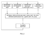
- the present invention comprises also a method for a steering servo system in a vehicle. The method is described below with reference to Figure 2 .
- the method comprises at least one of the following steps:
- the method further comprises:
- the centre of gravity signal contains information about changes in the position of the centre of gravity in the vehicle and, in particular, information about changes in the position of the centre of gravity in the vehicle in the longitudinal direction and/or sideways relative to a longitudinal symmetry line of the vehicle.
- the centre of gravity signal preferably also comprises information about the position of the centre of gravity in the vertical direction.
- the steering servo system thereafter calculates one or more control parameters, the steering wheel ratio (SGR) and servo assistance (SA) by applying a set of servo control rules as discussed above.
- SGR steering wheel ratio
- SA servo assistance
- the invention comprises also a computer programme adapted to performing the method steps described above.
- the computer programme is for example stored on a memory in the servo control unit.
Landscapes
- Engineering & Computer Science (AREA)
- Chemical & Material Sciences (AREA)
- Combustion & Propulsion (AREA)
- Transportation (AREA)
- Mechanical Engineering (AREA)
- Aviation & Aerospace Engineering (AREA)
- Physics & Mathematics (AREA)
- General Physics & Mathematics (AREA)
- Steering Control In Accordance With Driving Conditions (AREA)
Abstract
Description
- The present invention relates to a steering servo system for a vehicle, and a method for a steering servo system, according to the preambles of the independent claims. Although the invention is exemplified by application to a bus, it is equally applicable to a truck or a passenger car or any other vehicle equipped with a steering servo system.
- Buses and trucks, and also most passenger cars, are equipped today with a steering servo system to facilitate the steering of the vehicle. In simple terms, the way the servo system works is that a servo motor facilitates the steering of the vehicle on the basis of one or more input signals, e.g. steering wheel angle, steering wheel torque and yaw rate.
- The steering servo system helps inter alia to correct directional deviations which occur, for example, when the vehicle is subject to external disturbance, e.g. strong wind. Large vehicles, e.g. buses and trucks, are often sensitive to crosswind and there is risk of the driver losing control of the vehicle in strong crosswind.
- On passenger cars, (e.g. VW and Audi) the steering system can withstand crosswind disturbance but cannot speed up correction by the driver.
- Examples of a number of patents which all relate to steering servo systems for vehicles are cited below.
-
US-4,540,059 relates to a steering system intended to compensate for directional deviations of a vehicle caused by, for example, crosswind. Inter alia, a yaw sensor may be provided so that unwanted deviation of the vehicle due to strong crosswind can be avoided without the driver having to compensate manually by turning the steering wheel. -
GB-1,451,906 -
US-6,053,270 relates to steering wheel deflection correction systems for a vehicle, based inter alia on the vehicle's position on the road. - The general object of the present invention is to improve a vehicle's manoeuvrability, particularly in relation to external disturbance, e.g. wind action.
- The aforesaid object is achieved with the invention defined by the independent claims.
- Preferred embodiments are defined by the dependent claims.
- The invention is based on the inventor's observation that the sensitivity of, for example, buses to crosswind is because they are often rear-heavy with a consequently large distance between the point where the resulting wind load impinges and the centre of gravity. The result is a strong yaw moment which greatly affects the vehicle's directional stability. Moreover, the position of the centre of gravity on a bus varies greatly depending on how heavily laden it is, so the crosswind sensitivity may also vary. The variation in the position of the centre of gravity also affects steering sensation when driving in no crosswind.
- As well as the already mentioned unfavourable weight distribution, the steering in today's buses has only one steering gear ratio (which may depend on steering wheel angle) and one servo characteristic (which depends on steering wheel torque).
- A study has shown that changing the steering sensation (vehicle response as a function of steering wheel angle and steering wheel torque) and thereby minimising the corrective effort which the driver needs to apply greatly reduces directional deviation. This is achieved by change of steering gear ratio and servo assistance when crosswind disturbance is detected, and the magnitude of the change depends on current axle load distribution, i.e. the position of the centre of gravity. Steering sensation may thus be optimised for driving both with and without external disturbance, resulting in steering sensation which is appreciated by the driver when driving without disturbance, while at the same time improving safety when disturbance does occur.
- An advantage of the present invention is that the directional stability of the bus in crosswind is improved by modifying only the steering. This makes it possible to manufacture lighter and/or larger vehicles with better directional stability which are also more energy efficient.
- In brief, the invention is based on adapting the servo ratio and the servo assistance according to the vehicle's centre of gravity and at least one from among the parameters steering wheel angle, steering wheel torque and yaw rate.
- Thus what distinguishes the present invention from the state of the art is that account is also taken of the position of the vehicle's centre of gravity. The idea is to adapt the steering sensation according to the axle load distribution by change of steering gear ratio and servo assistance even when there is no external disturbance, e.g. crosswind. When external disturbance occurs, the steering sensation changes according to the axle load distribution with the object of minimising the maximum steering effort required of the driver. The present invention is preferably intended to help the driver, rather than to automate the steering, thereby reducing the risk of the system making a wrong correction.
-
-
Figure 1 is a schematic diagram of a steering servo system according to the present invention. -
Figure 2 is a flowchart illustrating the method according to the present invention. - The invention is described in detail below with reference to the attached drawings, using the following parameters and expressions:
- Steering wheel angle - SWA, also referred to as δh.
- Steering wheel torque - SWT, also referred to as Mh.
- Yaw rate - YR.
- Position of the vehicle's centre of gravity - COG.
-
Figure 1 depicts schematically how a steering wheel, via a steering wheel stem, acts upon the steering of a vehicle's wheels. It depicts a physical steering wheel stem, but a specialist within the field will appreciate that there other solutions, e.g. electrical transmission of control signals to auxiliary motors adapted to performing the steering locally. -
Figure 1 depicts asteering servo system 2 for a vehicle comprising at least one or more from among ayaw angle sensor 6 adapted to detecting current steering wheel angle and generating a steering wheel angle signal SWA in response to steering wheel angle detected, asteering torque sensor 8 adapted to detecting current steering wheel torque and generating a steering wheel torque signal SWT in response to torque detected, and ayaw rate sensor 8 adapted to detecting current yaw rate and generating a yaw rate signal YR in response to the yaw rate detected. These detected signals are adapted to being conveyed to aservo control unit 4. The steering wheel torque sensor and the yaw rate sensor are here referred to as a single sensor unit but may equally well take the form of two separate sensors. - The system further comprises one or more centre of
gravity sensors 10 connected to a centre ofgravity calculation unit 12 adapted to calculating the vehicle's centre of gravity on the basis of measured values received from the centre of gravity sensors, and to conveying at least a centre of gravity signal COG representing the vehicle's centre of gravity to saidservo control unit 4. The servo control unit is adapted to calculating one or more control parameters for the steering servo system in response to said centre of gravity signal and at least one from among the other signals. - Control parameters for the steering servo system comprise preferably the servo system's steering gear ratio SGR and servo assistance SA.
- These control parameters are defined as follows:
- Steering gear ratio SGR is defined as the transmission ratio used by the servo, i.e. it denotes the relationship between steering wheel deflection and pivoting of the vehicle's steered wheels.
- Servo assistance SA is defined as the force or torque which the servo exerts on the steering.
- Calculating the control parameters involves using a set of servo control rules which may in general terms be expressed as:

i.e. the steering gear ratio is a function (f) of one or more from among the parameters steering wheel angle, steering wheel torque, yaw rate and the position of the centre of gravity. Further parameters may be involved in the function, e.g. pressure signals from pressure sensors placed on the vehicle's respective sides to detect wind action on the vehicle.
i.e. the servo assistance is a function (g) of one or more from among the parameters steering wheel angle, steering wheel torque, yaw rate and the position of the centre of gravity. Further parameters may be involved in the function, e.g. pressure signals from pressure sensors. - The functions f and g used for calculating the steering gear ratio and the servo assistance are based on general relationships without taking into account the effects of the position of the centre of gravity. A specialist within the field will be familiar with a number of ways of calculating SGR and SA which will not be described in detail here. An example which may be cited is the aforesaid
US-6,053,270 which describes in detail the calculation of, for example, servo assistance based on steering wheel deflection and steering wheel torque. Other examples are referred to in the aforesaidGB-1,451,906 - Reducing the steering effort required of the driver to compensate for crosswind disturbance reduces the directional deviation due to crosswind disturbance and is achieved by increasing the servo assistance and reducing the steering gear ratio. This may generate a steering sensation which is not appreciated by the driver. Taking current position of centre of gravity/crosswind sensitivity into account makes it possible for adaptation of servo assistance and steering gear ratio respectively to be applied individually in order to maintain good steering sensation while at the same time the directional deviation is reduced by reduction of steering effort required.
- The effect of the position of the centre of gravity is due to the distance between the vehicle's centre of gravity and the steered wheels; the greater the distance, the greater the effect on SGR and SA.
- In crosswind, it is the distance between the point where the resulting wind load impinges on the vehicle and the position of the centre of gravity that affects SGR and SA. The longer this distance, the greater the effect of the control parameters.
- Where the steering servo system is implemented in, for example, a bus, the result with the bus fully refuelled but empty, i.e. with no passengers aboard, is an initial value for the position of the centre of gravity. Thereafter the position of the centre of gravity changes as passengers and luggage come on board. The same reasoning applies when loading a truck.
- According to an embodiment, the centre of gravity sensor takes the form of one or more axle load sensors which detect the load on the vehicle's axles and which may be situated close to the vehicle's suspension. If for example air suspension is used, the pressure in the air bellows may be used to provide a measure of axle load, in which case pressure sensors are preferably fitted close to the bellows but possibly also at a distance from them, and the pressure may be measured via a pipe or hose connected to the bellows.
- Another embodiment uses instead wire strain gauges fitted close to the suspension and providing via their output signal a measure of axle load.
- The position of centre of gravity signal contains information about the position of the centre of gravity in the vehicle's longitudinal direction relative to a longitudinal symmetry line of the vehicle, but preferably also information about the position of the centre of gravity sideways, and also vertically, relative to the vehicle's longitudinal symmetry axis.
- The centre of gravity signal preferably further contains information about changes in the position of the centre of gravity in the vehicle.
- The steering wheel angle sensor is preferably an optical sensor, but resistive or inductive sensors may also be used.
- The steering wheel torque sensor measures the torque exerted by the vehicle's steering wheel, which may be example be measured by the inductive or magnetic sensors.
- The yaw rate sensor takes the form in a preferred embodiment of a gyro-based sensor which detects the vehicle's deviation relative to a reference direction.
- The
servo control unit 4 itself comprises a calculation unit, a memory and input and output units for receiving and delivering signals. The servo control unit may for example take the form of a PC or a dedicated device specially adapted for the purpose. - The present invention comprises also a method for a steering servo system in a vehicle. The method is described below with reference to
Figure 2 . - The method comprises at least one of the following steps:
- detecting current steering wheel angle and generating a steering wheel angle signal in response thereto and conveying the signal to a servo control unit;
- detecting current steering wheel torque and generating a steering wheel torque signal in response thereto and conveying the signal to said servo control unit, and
- detecting current yaw rate and generating a yaw rate signal in response thereto and conveying the signal to said servo control unit.
- The method further comprises:
- calculating the vehicle's centre of gravity and conveying at least a centre of gravity signal representing the vehicle's centre of gravity to said servo control unit. The servo control unit is adapted to calculating one or more control parameters for the steering servo system in response to said centre of gravity signal and at least one from among the other signals.
- The centre of gravity signal contains information about changes in the position of the centre of gravity in the vehicle and, in particular, information about changes in the position of the centre of gravity in the vehicle in the longitudinal direction and/or sideways relative to a longitudinal symmetry line of the vehicle. The centre of gravity signal preferably also comprises information about the position of the centre of gravity in the vertical direction.
- The steering servo system thereafter calculates one or more control parameters, the steering wheel ratio (SGR) and servo assistance (SA) by applying a set of servo control rules as discussed above.
- The invention comprises also a computer programme adapted to performing the method steps described above. The computer programme is for example stored on a memory in the servo control unit.
- The present invention is not limited to the preferred embodiments described above. Various alternatives, modifications and equivalents may be used. The above embodiments are therefore not to be regarded as limiting the scope of protection of the invention defined by the attached claims.
Claims (15)
- A steering servo system (2) for a vehicle comprising at least one or more from among a steering wheel angle sensor (6) adapted to detecting current steering wheel angle and generating a steering wheel angle signal (SWA) in response thereto, a steering wheel torque sensor (8) adapted to detecting current steering wheel torque and generating a steering wheel torque signal (SWT) in response thereto, and a yaw rate sensor (8) adapted to detecting current yaw rate and generating a yaw rate signal (YR) in response thereto, said signals being adapted to being conveyed to a servo control unit (4), characterised in that the system further comprises one or more centre of gravity sensors (10) connected to a centre of gravity calculation unit (12) which is adapted to calculating the vehicle's centre of gravity on the basis of measured values received from the centre of gravity sensors and to conveying at least a centre of gravity signal (COG) representing the vehicle's centre of gravity to said servo control unit, which servo control unit is adapted to calculating one or more parameters (SGR, SA) for the servo steering system in response to said centre of gravity signal and at least one from among the other signals.
- A steering servo system according to claim 1, in which the centre of gravity sensor (10) takes the form of one or more axle load sensors.
- A steering servo system according to claim 1, in which the centre of gravity signal (COG) contains information about changes in the position of the centre of gravity in the vehicle.
- A steering servo system according to claim 3, in which the centre of gravity signal (COG) contains information about changes in the position of the centre of gravity in the vehicle in the longitudinal direction relative to a longitudinal symmetry line of the vehicle.
- A steering servo system according to any one of the foregoing claims, in which the centre of gravity signal (COG) contains information about changes in the position of the centre of gravity in the vehicle sideways relative to a longitudinal symmetry line of the vehicle.
- A steering servo system according to claim 1, in which said centre of gravity sensors are situated close to the vehicle's suspension.
- A steering servo system according to claim 1, in which said servo control unit calculates said one or more control parameters by applying a set of servo control rules.
- A steering servo system according to claim 1, in which said control parameters comprise the steering gear ratio (SGR) and servo assistance (SA).
- A method for a steering servo system (2) in a vehicle, which method comprises at least one of the steps of- detecting current steering wheel angle and generating a steering wheel angle signal (SWA) in response thereto and conveying the signal to a servo control unit (4),- detecting current steering wheel torque and generating a steering wheel torque signal (SWT) in response thereto and conveying the signal to said servo control unit (4), and- detecting current yaw rate and generating a yaw rate signal (YR) in response thereto and conveying the signal to said servo control unit (4),
characterised in that the method further comprises- calculating the vehicle's centre of gravity and conveying at least a centre of gravity signal (COG) representing the vehicle's centre of gravity to said servo control unit (4), which servo control unit is adapted to calculating one or more control parameters (SGR, SA) for the steering servo system in response to said centre of gravity signal and at least one from among the other signals. - A method according to claim 9, in which the centre of gravity signal contains information about changes in the position of the centre of gravity in the vehicle.
- A method according to claim 10, in which the centre of gravity signal contains information about changes in the position of the centre of gravity in the vehicle in the longitudinal direction relative to a longitudinal symmetry line of the vehicle.
- A method according to either of claims 10 and 11, in which the centre of gravity signal contains information about changes in the position of the centre of gravity in the vehicle sideways relative to a longitudinal symmetry line of the vehicle.
- A method according to claim 9, in which said servo control unit calculates said one or more control parameters by applying a set of servo control rules.
- A method according to claim method 13, in which said control parameters comprise the steering gear ratio (SGR) and servo assistance (SA).
- A computer programme adapted to performing the method steps according to any one of claims 9-14.
Applications Claiming Priority (1)
| Application Number | Priority Date | Filing Date | Title |
|---|---|---|---|
| SE0950361A SE533784C2 (en) | 2009-05-20 | 2009-05-20 | Power steering system |
Publications (3)
| Publication Number | Publication Date |
|---|---|
| EP2253527A2 true EP2253527A2 (en) | 2010-11-24 |
| EP2253527A3 EP2253527A3 (en) | 2011-01-05 |
| EP2253527B1 EP2253527B1 (en) | 2012-11-28 |
Family
ID=42306653
Family Applications (1)
| Application Number | Title | Priority Date | Filing Date |
|---|---|---|---|
| EP10162927A Active EP2253527B1 (en) | 2009-05-20 | 2010-05-17 | Steering servo system |
Country Status (5)
| Country | Link |
|---|---|
| EP (1) | EP2253527B1 (en) |
| CN (1) | CN101890979B (en) |
| BR (1) | BRPI1002034B1 (en) |
| ES (1) | ES2399506T3 (en) |
| SE (1) | SE533784C2 (en) |
Cited By (1)
| Publication number | Priority date | Publication date | Assignee | Title |
|---|---|---|---|---|
| US9807352B2 (en) | 2011-06-28 | 2017-10-31 | Volkswagen Ag | Method and device for parking a vehicle |
Families Citing this family (3)
| Publication number | Priority date | Publication date | Assignee | Title |
|---|---|---|---|---|
| CN103228522B (en) * | 2010-11-29 | 2016-05-25 | 日产自动车株式会社 | Vehicle and handling maneuver control method thereof |
| JP5998630B2 (en) * | 2012-05-17 | 2016-09-28 | いすゞ自動車株式会社 | Power steering system, vehicle equipped with the same, and control method thereof |
| DE102014000266B4 (en) * | 2014-01-09 | 2016-05-19 | Daimler Ag | Method for operating a vehicle |
Citations (3)
| Publication number | Priority date | Publication date | Assignee | Title |
|---|---|---|---|---|
| GB1451906A (en) | 1972-11-13 | 1976-10-06 | Bosch Gmbh Robert | Steering gear controls for motor vehicles |
| US4540059A (en) | 1982-06-07 | 1985-09-10 | Nissan Motor Co., Ltd. | Vehicle steering system |
| US6053270A (en) | 1995-11-02 | 2000-04-25 | Honda Giken Kogyo Kabushiki Kaisha | Steering angle correcting system in vehicle |
Family Cites Families (5)
| Publication number | Priority date | Publication date | Assignee | Title |
|---|---|---|---|---|
| JPS60163767A (en) * | 1984-02-07 | 1985-08-26 | Kayaba Ind Co Ltd | Power-operated steering device |
| DE10013711A1 (en) * | 2000-03-20 | 2001-10-11 | Bosch Gmbh Robert | Power assisted steering system of a motor vehicle |
| JP4032985B2 (en) * | 2003-02-07 | 2008-01-16 | 日産自動車株式会社 | Vehicle motion control device |
| US7451032B2 (en) * | 2004-06-02 | 2008-11-11 | Ford Global Technologies, Llc | System and method for determining desired yaw rate and lateral velocity for use in a vehicle dynamic control system |
| CN2934008Y (en) * | 2006-08-18 | 2007-08-15 | 浙江大学 | Vehicle Electric Power Steering Controller |
-
2009
- 2009-05-20 SE SE0950361A patent/SE533784C2/en unknown
-
2010
- 2010-05-14 BR BRPI1002034-9A patent/BRPI1002034B1/en active IP Right Grant
- 2010-05-17 ES ES10162927T patent/ES2399506T3/en active Active
- 2010-05-17 EP EP10162927A patent/EP2253527B1/en active Active
- 2010-05-18 CN CN201010183453.4A patent/CN101890979B/en active Active
Patent Citations (3)
| Publication number | Priority date | Publication date | Assignee | Title |
|---|---|---|---|---|
| GB1451906A (en) | 1972-11-13 | 1976-10-06 | Bosch Gmbh Robert | Steering gear controls for motor vehicles |
| US4540059A (en) | 1982-06-07 | 1985-09-10 | Nissan Motor Co., Ltd. | Vehicle steering system |
| US6053270A (en) | 1995-11-02 | 2000-04-25 | Honda Giken Kogyo Kabushiki Kaisha | Steering angle correcting system in vehicle |
Cited By (1)
| Publication number | Priority date | Publication date | Assignee | Title |
|---|---|---|---|---|
| US9807352B2 (en) | 2011-06-28 | 2017-10-31 | Volkswagen Ag | Method and device for parking a vehicle |
Also Published As
| Publication number | Publication date |
|---|---|
| EP2253527B1 (en) | 2012-11-28 |
| EP2253527A3 (en) | 2011-01-05 |
| ES2399506T3 (en) | 2013-04-01 |
| CN101890979A (en) | 2010-11-24 |
| BRPI1002034A2 (en) | 2011-07-05 |
| SE533784C2 (en) | 2011-01-11 |
| CN101890979B (en) | 2014-10-01 |
| SE0950361A1 (en) | 2010-11-21 |
| BRPI1002034B1 (en) | 2020-11-17 |
Similar Documents
| Publication | Publication Date | Title |
|---|---|---|
| US11639178B2 (en) | Vehicle control method and device | |
| EP2112053B1 (en) | Yaw stability control system | |
| US8078361B2 (en) | Method and device for assisting a motor vehicle server in the vehicle stabilization | |
| US6640171B2 (en) | Motor vehicle with supplemental rear steering having open and closed loop modes | |
| US8670905B2 (en) | Vehicle stability control method and system | |
| US7418329B2 (en) | Steering control apparatus for a vehicle | |
| EP3057848B1 (en) | Method in order to control vehicle behaviour | |
| US8209089B2 (en) | Vehicular steering apparatus | |
| US20130066522A1 (en) | Steering support system for a two-wheeler as well as a control for such a steering support system | |
| US20090319128A1 (en) | Method and System for Determining an Optimal Steering Angle in Understeer Situations in a Vehicle | |
| US20200231204A1 (en) | Control device | |
| CN107848509A (en) | Method for aiding in driver when ponding on road surface skids | |
| EP2253527B1 (en) | Steering servo system | |
| US9205866B2 (en) | Steering control apparatus and method | |
| CN103770782A (en) | Control method for lane keeping assist of vehicle and apparatus for lane keeping assist implementing the same | |
| EP2611662B1 (en) | Method of controlling a torque vectoring mechanism and torque vectoring system | |
| CN101516716B (en) | Device and method for monitoring the turn command to a steered rear wheel | |
| US20080033612A1 (en) | Device and Method for Stabilizing a Motor Vehicle | |
| CN101113932A (en) | Dynamic ride regulator with torque sensor integrated in the steering gear | |
| KR102895240B1 (en) | System and method for controlling lateral force | |
| WO2013182257A1 (en) | Sensory feedback when driving near a vehicle's handling limits | |
| CN105752059A (en) | Vehicle stability control method | |
| US20020022915A1 (en) | Motor vehicle with supplemental rear steering having open and closed loop modes | |
| CN114802432A (en) | Sideslip angle adjustment active steering return | |
| JP2007118743A (en) | Vehicle steering system |
Legal Events
| Date | Code | Title | Description |
|---|---|---|---|
| PUAI | Public reference made under article 153(3) epc to a published international application that has entered the european phase |
Free format text: ORIGINAL CODE: 0009012 |
|
| AK | Designated contracting states |
Kind code of ref document: A2 Designated state(s): AL AT BE BG CH CY CZ DE DK EE ES FI FR GB GR HR HU IE IS IT LI LT LU LV MC MK MT NL NO PL PT RO SE SI SK SM TR |
|
| AX | Request for extension of the european patent |
Extension state: BA ME RS |
|
| PUAL | Search report despatched |
Free format text: ORIGINAL CODE: 0009013 |
|
| AK | Designated contracting states |
Kind code of ref document: A3 Designated state(s): AL AT BE BG CH CY CZ DE DK EE ES FI FR GB GR HR HU IE IS IT LI LT LU LV MC MK MT NL NO PL PT RO SE SI SK SM TR |
|
| AX | Request for extension of the european patent |
Extension state: BA ME RS |
|
| 17P | Request for examination filed |
Effective date: 20110705 |
|
| 17Q | First examination report despatched |
Effective date: 20111221 |
|
| GRAP | Despatch of communication of intention to grant a patent |
Free format text: ORIGINAL CODE: EPIDOSNIGR1 |
|
| GRAS | Grant fee paid |
Free format text: ORIGINAL CODE: EPIDOSNIGR3 |
|
| GRAA | (expected) grant |
Free format text: ORIGINAL CODE: 0009210 |
|
| AK | Designated contracting states |
Kind code of ref document: B1 Designated state(s): AL AT BE BG CH CY CZ DE DK EE ES FI FR GB GR HR HU IE IS IT LI LT LU LV MC MK MT NL NO PL PT RO SE SI SK SM TR |
|
| REG | Reference to a national code |
Ref country code: GB Ref legal event code: FG4D |
|
| REG | Reference to a national code |
Ref country code: CH Ref legal event code: EP |
|
| REG | Reference to a national code |
Ref country code: AT Ref legal event code: REF Ref document number: 586001 Country of ref document: AT Kind code of ref document: T Effective date: 20121215 |
|
| REG | Reference to a national code |
Ref country code: IE Ref legal event code: FG4D |
|
| REG | Reference to a national code |
Ref country code: DE Ref legal event code: R096 Ref document number: 602010003791 Country of ref document: DE Effective date: 20130117 |
|
| REG | Reference to a national code |
Ref country code: ES Ref legal event code: FG2A Ref document number: 2399506 Country of ref document: ES Kind code of ref document: T3 Effective date: 20130401 |
|
| REG | Reference to a national code |
Ref country code: AT Ref legal event code: MK05 Ref document number: 586001 Country of ref document: AT Kind code of ref document: T Effective date: 20121128 |
|
| REG | Reference to a national code |
Ref country code: NL Ref legal event code: VDEP Effective date: 20121128 |
|
| REG | Reference to a national code |
Ref country code: LT Ref legal event code: MG4D |
|
| PG25 | Lapsed in a contracting state [announced via postgrant information from national office to epo] |
Ref country code: LT Free format text: LAPSE BECAUSE OF FAILURE TO SUBMIT A TRANSLATION OF THE DESCRIPTION OR TO PAY THE FEE WITHIN THE PRESCRIBED TIME-LIMIT Effective date: 20121128 Ref country code: SE Free format text: LAPSE BECAUSE OF FAILURE TO SUBMIT A TRANSLATION OF THE DESCRIPTION OR TO PAY THE FEE WITHIN THE PRESCRIBED TIME-LIMIT Effective date: 20121128 Ref country code: NO Free format text: LAPSE BECAUSE OF FAILURE TO SUBMIT A TRANSLATION OF THE DESCRIPTION OR TO PAY THE FEE WITHIN THE PRESCRIBED TIME-LIMIT Effective date: 20130228 Ref country code: FI Free format text: LAPSE BECAUSE OF FAILURE TO SUBMIT A TRANSLATION OF THE DESCRIPTION OR TO PAY THE FEE WITHIN THE PRESCRIBED TIME-LIMIT Effective date: 20121128 |
|
| PG25 | Lapsed in a contracting state [announced via postgrant information from national office to epo] |
Ref country code: PT Free format text: LAPSE BECAUSE OF FAILURE TO SUBMIT A TRANSLATION OF THE DESCRIPTION OR TO PAY THE FEE WITHIN THE PRESCRIBED TIME-LIMIT Effective date: 20130328 Ref country code: LV Free format text: LAPSE BECAUSE OF FAILURE TO SUBMIT A TRANSLATION OF THE DESCRIPTION OR TO PAY THE FEE WITHIN THE PRESCRIBED TIME-LIMIT Effective date: 20121128 Ref country code: SI Free format text: LAPSE BECAUSE OF FAILURE TO SUBMIT A TRANSLATION OF THE DESCRIPTION OR TO PAY THE FEE WITHIN THE PRESCRIBED TIME-LIMIT Effective date: 20121128 Ref country code: GR Free format text: LAPSE BECAUSE OF FAILURE TO SUBMIT A TRANSLATION OF THE DESCRIPTION OR TO PAY THE FEE WITHIN THE PRESCRIBED TIME-LIMIT Effective date: 20130301 Ref country code: BE Free format text: LAPSE BECAUSE OF FAILURE TO SUBMIT A TRANSLATION OF THE DESCRIPTION OR TO PAY THE FEE WITHIN THE PRESCRIBED TIME-LIMIT Effective date: 20121128 Ref country code: PL Free format text: LAPSE BECAUSE OF FAILURE TO SUBMIT A TRANSLATION OF THE DESCRIPTION OR TO PAY THE FEE WITHIN THE PRESCRIBED TIME-LIMIT Effective date: 20121128 |
|
| PG25 | Lapsed in a contracting state [announced via postgrant information from national office to epo] |
Ref country code: AT Free format text: LAPSE BECAUSE OF FAILURE TO SUBMIT A TRANSLATION OF THE DESCRIPTION OR TO PAY THE FEE WITHIN THE PRESCRIBED TIME-LIMIT Effective date: 20121128 |
|
| PG25 | Lapsed in a contracting state [announced via postgrant information from national office to epo] |
Ref country code: EE Free format text: LAPSE BECAUSE OF FAILURE TO SUBMIT A TRANSLATION OF THE DESCRIPTION OR TO PAY THE FEE WITHIN THE PRESCRIBED TIME-LIMIT Effective date: 20121128 Ref country code: CZ Free format text: LAPSE BECAUSE OF FAILURE TO SUBMIT A TRANSLATION OF THE DESCRIPTION OR TO PAY THE FEE WITHIN THE PRESCRIBED TIME-LIMIT Effective date: 20121128 Ref country code: BG Free format text: LAPSE BECAUSE OF FAILURE TO SUBMIT A TRANSLATION OF THE DESCRIPTION OR TO PAY THE FEE WITHIN THE PRESCRIBED TIME-LIMIT Effective date: 20130228 Ref country code: SK Free format text: LAPSE BECAUSE OF FAILURE TO SUBMIT A TRANSLATION OF THE DESCRIPTION OR TO PAY THE FEE WITHIN THE PRESCRIBED TIME-LIMIT Effective date: 20121128 Ref country code: DK Free format text: LAPSE BECAUSE OF FAILURE TO SUBMIT A TRANSLATION OF THE DESCRIPTION OR TO PAY THE FEE WITHIN THE PRESCRIBED TIME-LIMIT Effective date: 20121128 |
|
| PG25 | Lapsed in a contracting state [announced via postgrant information from national office to epo] |
Ref country code: RO Free format text: LAPSE BECAUSE OF FAILURE TO SUBMIT A TRANSLATION OF THE DESCRIPTION OR TO PAY THE FEE WITHIN THE PRESCRIBED TIME-LIMIT Effective date: 20121128 Ref country code: NL Free format text: LAPSE BECAUSE OF FAILURE TO SUBMIT A TRANSLATION OF THE DESCRIPTION OR TO PAY THE FEE WITHIN THE PRESCRIBED TIME-LIMIT Effective date: 20121128 |
|
| PLBE | No opposition filed within time limit |
Free format text: ORIGINAL CODE: 0009261 |
|
| STAA | Information on the status of an ep patent application or granted ep patent |
Free format text: STATUS: NO OPPOSITION FILED WITHIN TIME LIMIT |
|
| 26N | No opposition filed |
Effective date: 20130829 |
|
| PG25 | Lapsed in a contracting state [announced via postgrant information from national office to epo] |
Ref country code: CY Free format text: LAPSE BECAUSE OF FAILURE TO SUBMIT A TRANSLATION OF THE DESCRIPTION OR TO PAY THE FEE WITHIN THE PRESCRIBED TIME-LIMIT Effective date: 20121128 |
|
| REG | Reference to a national code |
Ref country code: DE Ref legal event code: R097 Ref document number: 602010003791 Country of ref document: DE Effective date: 20130829 |
|
| PG25 | Lapsed in a contracting state [announced via postgrant information from national office to epo] |
Ref country code: MC Free format text: LAPSE BECAUSE OF FAILURE TO SUBMIT A TRANSLATION OF THE DESCRIPTION OR TO PAY THE FEE WITHIN THE PRESCRIBED TIME-LIMIT Effective date: 20121128 |
|
| PG25 | Lapsed in a contracting state [announced via postgrant information from national office to epo] |
Ref country code: HR Free format text: LAPSE BECAUSE OF FAILURE TO SUBMIT A TRANSLATION OF THE DESCRIPTION OR TO PAY THE FEE WITHIN THE PRESCRIBED TIME-LIMIT Effective date: 20130731 |
|
| REG | Reference to a national code |
Ref country code: IE Ref legal event code: MM4A |
|
| PG25 | Lapsed in a contracting state [announced via postgrant information from national office to epo] |
Ref country code: IE Free format text: LAPSE BECAUSE OF NON-PAYMENT OF DUE FEES Effective date: 20130517 |
|
| REG | Reference to a national code |
Ref country code: CH Ref legal event code: PL |
|
| PG25 | Lapsed in a contracting state [announced via postgrant information from national office to epo] |
Ref country code: LI Free format text: LAPSE BECAUSE OF NON-PAYMENT OF DUE FEES Effective date: 20140531 Ref country code: CH Free format text: LAPSE BECAUSE OF NON-PAYMENT OF DUE FEES Effective date: 20140531 |
|
| PG25 | Lapsed in a contracting state [announced via postgrant information from national office to epo] |
Ref country code: MT Free format text: LAPSE BECAUSE OF FAILURE TO SUBMIT A TRANSLATION OF THE DESCRIPTION OR TO PAY THE FEE WITHIN THE PRESCRIBED TIME-LIMIT Effective date: 20121128 |
|
| REG | Reference to a national code |
Ref country code: FR Ref legal event code: PLFP Year of fee payment: 6 |
|
| PG25 | Lapsed in a contracting state [announced via postgrant information from national office to epo] |
Ref country code: SM Free format text: LAPSE BECAUSE OF FAILURE TO SUBMIT A TRANSLATION OF THE DESCRIPTION OR TO PAY THE FEE WITHIN THE PRESCRIBED TIME-LIMIT Effective date: 20121128 |
|
| PG25 | Lapsed in a contracting state [announced via postgrant information from national office to epo] |
Ref country code: TR Free format text: LAPSE BECAUSE OF FAILURE TO SUBMIT A TRANSLATION OF THE DESCRIPTION OR TO PAY THE FEE WITHIN THE PRESCRIBED TIME-LIMIT Effective date: 20121128 |
|
| PG25 | Lapsed in a contracting state [announced via postgrant information from national office to epo] |
Ref country code: LU Free format text: LAPSE BECAUSE OF NON-PAYMENT OF DUE FEES Effective date: 20130517 Ref country code: MK Free format text: LAPSE BECAUSE OF FAILURE TO SUBMIT A TRANSLATION OF THE DESCRIPTION OR TO PAY THE FEE WITHIN THE PRESCRIBED TIME-LIMIT Effective date: 20121128 Ref country code: HU Free format text: LAPSE BECAUSE OF FAILURE TO SUBMIT A TRANSLATION OF THE DESCRIPTION OR TO PAY THE FEE WITHIN THE PRESCRIBED TIME-LIMIT; INVALID AB INITIO Effective date: 20100517 |
|
| PGFP | Annual fee paid to national office [announced via postgrant information from national office to epo] |
Ref country code: ES Payment date: 20150413 Year of fee payment: 6 Ref country code: GB Payment date: 20150513 Year of fee payment: 6 |
|
| PGFP | Annual fee paid to national office [announced via postgrant information from national office to epo] |
Ref country code: IT Payment date: 20150515 Year of fee payment: 6 |
|
| REG | Reference to a national code |
Ref country code: FR Ref legal event code: PLFP Year of fee payment: 7 |
|
| PG25 | Lapsed in a contracting state [announced via postgrant information from national office to epo] |
Ref country code: IS Free format text: LAPSE BECAUSE OF FAILURE TO SUBMIT A TRANSLATION OF THE DESCRIPTION OR TO PAY THE FEE WITHIN THE PRESCRIBED TIME-LIMIT Effective date: 20121128 |
|
| GBPC | Gb: european patent ceased through non-payment of renewal fee |
Effective date: 20160517 |
|
| PG25 | Lapsed in a contracting state [announced via postgrant information from national office to epo] |
Ref country code: IT Free format text: LAPSE BECAUSE OF NON-PAYMENT OF DUE FEES Effective date: 20160517 |
|
| REG | Reference to a national code |
Ref country code: FR Ref legal event code: PLFP Year of fee payment: 8 |
|
| PG25 | Lapsed in a contracting state [announced via postgrant information from national office to epo] |
Ref country code: GB Free format text: LAPSE BECAUSE OF NON-PAYMENT OF DUE FEES Effective date: 20160517 |
|
| REG | Reference to a national code |
Ref country code: FR Ref legal event code: PLFP Year of fee payment: 9 |
|
| PG25 | Lapsed in a contracting state [announced via postgrant information from national office to epo] |
Ref country code: ES Free format text: LAPSE BECAUSE OF NON-PAYMENT OF DUE FEES Effective date: 20160518 |
|
| PG25 | Lapsed in a contracting state [announced via postgrant information from national office to epo] |
Ref country code: AL Free format text: LAPSE BECAUSE OF FAILURE TO SUBMIT A TRANSLATION OF THE DESCRIPTION OR TO PAY THE FEE WITHIN THE PRESCRIBED TIME-LIMIT Effective date: 20121128 |
|
| REG | Reference to a national code |
Ref country code: ES Ref legal event code: FD2A Effective date: 20181121 |
|
| REG | Reference to a national code |
Ref country code: FR Ref legal event code: PLFP Year of fee payment: 14 |
|
| P01 | Opt-out of the competence of the unified patent court (upc) registered |
Effective date: 20230518 |
|
| PGFP | Annual fee paid to national office [announced via postgrant information from national office to epo] |
Ref country code: DE Payment date: 20250402 Year of fee payment: 16 |
|
| PGFP | Annual fee paid to national office [announced via postgrant information from national office to epo] |
Ref country code: FR Payment date: 20250401 Year of fee payment: 16 |