EP2253514A1 - Knee airbag device with column - Google Patents
Knee airbag device with column Download PDFInfo
- Publication number
- EP2253514A1 EP2253514A1 EP09720013A EP09720013A EP2253514A1 EP 2253514 A1 EP2253514 A1 EP 2253514A1 EP 09720013 A EP09720013 A EP 09720013A EP 09720013 A EP09720013 A EP 09720013A EP 2253514 A1 EP2253514 A1 EP 2253514A1
- Authority
- EP
- European Patent Office
- Prior art keywords
- knee airbag
- column
- inflator
- gas
- airbag device
- Prior art date
- Legal status (The legal status is an assumption and is not a legal conclusion. Google has not performed a legal analysis and makes no representation as to the accuracy of the status listed.)
- Granted
Links
Images




Classifications
-
- B—PERFORMING OPERATIONS; TRANSPORTING
- B60—VEHICLES IN GENERAL
- B60R—VEHICLES, VEHICLE FITTINGS, OR VEHICLE PARTS, NOT OTHERWISE PROVIDED FOR
- B60R21/00—Arrangements or fittings on vehicles for protecting or preventing injuries to occupants or pedestrians in case of accidents or other traffic risks
- B60R21/02—Occupant safety arrangements or fittings, e.g. crash pads
- B60R21/16—Inflatable occupant restraints or confinements designed to inflate upon impact or impending impact, e.g. air bags
- B60R21/20—Arrangements for storing inflatable members in their non-use or deflated condition; Arrangement or mounting of air bag modules or components
- B60R21/203—Arrangements for storing inflatable members in their non-use or deflated condition; Arrangement or mounting of air bag modules or components in steering wheels or steering columns
-
- B—PERFORMING OPERATIONS; TRANSPORTING
- B60—VEHICLES IN GENERAL
- B60R—VEHICLES, VEHICLE FITTINGS, OR VEHICLE PARTS, NOT OTHERWISE PROVIDED FOR
- B60R21/00—Arrangements or fittings on vehicles for protecting or preventing injuries to occupants or pedestrians in case of accidents or other traffic risks
- B60R21/02—Occupant safety arrangements or fittings, e.g. crash pads
- B60R21/16—Inflatable occupant restraints or confinements designed to inflate upon impact or impending impact, e.g. air bags
- B60R21/23—Inflatable members
- B60R21/231—Inflatable members characterised by their shape, construction or spatial configuration
- B60R2021/23169—Inflatable members characterised by their shape, construction or spatial configuration specially adapted for knee protection
Definitions
- the present invention relates to a column-mounted knee airbag device.
- Patent Document 1 Japanese Patent Application Laid-Open (JP-A) No. 9-104317
- Patent Document 2 JP-ANo. 2002-37003
- an object of the present invention is to provide a column-mounted knee airbag device that can correctly deploy a knee airbag even when the position of a steering column has changed due to a telescopic function.
- a column-mounted knee airbag device includes: a knee airbag used for protecting the knees of a driver, the knee airbag being folded inside a column cover that covers a steering column having a telescopic function, the knee airbag opening an airbag door provided in the column cover by deployment pressure when supplied with gas and deploying between an instrument panel and the knees of the driver; an inflator installed at the inside of the column cover, the inflator being actuated and generating gas when a vehicle impact is detected or predicted, wherein a gas supply opening for supplying gas from the inflator to the airbag is disposed in a position further to the rear than the instrument panel in the vehicle front-rear direction, when viewed from the side with the steering column having a telescopic function in a state positioned furthest to the front in the vehicle front-rear direction.
- gas is generated when the inflator is actuated when a vehicle frontal impact is detected or predicted, and this gas is supplied to the airbag through the gas supply opening.
- the knee airbag opens the airbag door by the deployment pressure as the knee airbag progressively deploys (inflates), and deploys outside the column cover between the instrument panel and the knees of the driver. Protection is thereby achieved of the knees of the driver.
- the gas supply opening is positioned to the rear of the instrument panel in the vehicle front-rear direction, namely on the driver knee side of the instrument panel, when the steering column is positioned furthest to the front in the vehicle front-rear direction (referred to below as the telescopic short state) by the telescopic function. Therefore, there are no occasions in the telescopic short state when the knee airbag (a portion thereof) initiates deployment at the inside of the instrument panel. The airbag can thereby be rapidly deployed in front of the knees of the driver (between the knees and the outside face of the instrument panel).
- the knee airbag can be correctly deployed even when the position of a steering column has changed due to a telescopic function.
- the above aspect may be configured such that the gas supply opening is disposed inside the knee airbag such that gas is ejected the toward both sides in the vehicle width direction.
- the above aspects may be configured such that: the longitudinal direction of the inflator is along the vehicle front-rear direction; and the gas supply opening is a gas ejection hole at a rear end portion of the inflator in the vehicle front-rear direction, opening toward the vehicle width direction.
- the gas ejection hole provided to the rear end portion of the inflator with longitudinal direction along the vehicle front-rear direction (substantially parallel to the steering column), is the gas supply opening for supplying gas to the knee airbag. Consequently, the knee airbag can be correctly deployed by means of a simple structure, even when the position of the steering column has changed due to a telescopic function.
- the above aspects may be configured such that: the longitudinal direction of the inflator is along the vehicle front-rear direction and a gas ejection hole is provided at a front end side of the inflator in the vehicle front-rear direction; a diffuser for guiding gas from the gas ejection hole to the airbag is fixed to the inflator; and the gas supply opening is a gas supply hole at a rear end portion of the diffuser in the vehicle front-rear direction, opening toward the vehicle width direction.
- the gas ejected from the gas ejection hole of the inflator passes inside the diffuser and is supplied from the gas ejection hole, provided as the gas supply opening at the rear portion of the diffuser, to the airbag. Since in the present column-mounted knee airbag device the gas ejection hole of the inflator is positioned at the front end side in the vehicle front-rear direction, the wiring connection side of the inflator can be disposed facing rearward in the vehicle front-rear direction, and connecting up the inflator becomes easy.
- the above aspect may be configured such that the diffuser covers the inflator from an outer peripheral side so as to guide gas from the gas ejection hole to the gas supply hole through a space formed between the diffuser and an outer peripheral face of the inflator.
- gas ejected from the gas ejection hole of the inflator and passing through the space formed between the outer peripheral face of the inflator and the diffuser is supplied to the knee airbag from the gas supply hole provided at the rear end portion of the diffuser.
- the above aspect may be configured such that: the longitudinal direction of the inflator is along the vehicle front-rear direction, a gas ejection hole is opened in an outer peripheral face of the inflator and the inflator is covered from the outer peripheral side by a diffuser for guiding gas from the gas ejection hole to the knee airbag; and the gas supply openings are open ends formed at both sides in the vehicle width direction in a space between an inner peripheral face of the diffuser and the outer peripheral face of the inflator.
- the gas ejected from the gas ejection hole of the inflator passes through inside the diffuser, and is supplied into the knee airbag through the respective gas supply openings, which are the two open ends of the diffuser in the vehicle width direction.
- the above aspect may be configured such that: the knee airbag has a pair of upper and lower straps for restricting the thickness of the knee airbag in the vehicle front-rear direction when in the deployed state; and the gas supply opening is disposed inside the knee airbag between the pair of straps so as to be in the vicinity of the upper strap of the pair of straps when the airbag is in the deployed state.
- the deployed thickness, in the vehicle front-rear direction, of the knee airbag supplied with gas and deployed is restricted by the pair of upper and lower straps. Since the opening supplying gas from the inflator in this deployed state is disposed in the vicinity of the upper strap, the upper portion of the knee airbag can be rapidly deployed.
- the column-mounted knee airbag device has the excellent effect in that the knee airbag can be correctly deployed even when the position of a steering column has changed due to a telescopic function.
- FIG. 1 is a partially cut-away side view showing a column-mounted knee airbag device according to a first exemplary embodiment of the present invention.
- FIG. 1 shows the outline overall configuration of a steering column 12 in a partially cut-away side view.
- the steering column 12 is configured to include main portions of: a steering column main body 14 serving as the steering column of the present invention; a column cover 15, covering the rear end of the steering column main body 14 in the vehicle front-rear direction; and a steering wheel 20, disposed at a rear end portion of the steering column main body 14 in the vehicle front-rear direction.
- the steering column 12 is inserted in a forward tilted state through an opening 24 formed in an instrument panel 22 so as to face toward the driver's seat.
- the steering column 12 is supported on instrument panel reinforcement (not shown in the figures), spanning across inside the instrument panel 22 between left and right front pillars, via a tilting and telescoping drive mechanism 25.
- the column cover 15 In the assembled state of the steering column 12 to the vehicle body, the column cover 15 is disposed in a state such that a portion at the front end of the column cover 15 is disposed inside the instrument panel 22, with the remaining portion of the column cover 15 protrudes out into the cabin C.
- the column cover 15 is of an upper and lower two part structure. Specifically, the column cover 15 is configured in a cylindrical shape overall from a column upper cover 16 configuring the upper portion of the column cover 15 in the vehicle up-down direction and a column lower cover 18.
- the steering column main body 14 is equipped with a column tube 26 forming a substantially circular cylindrical shape, with a steering main shaft 28 rotatably supported in an axial portion of the column tube 26.
- the steering main shaft 28 is divided in the column axial direction into two portions, with an upper side shaft 28A and a lower side shaft (not shown in the figures) connected together by a spline fitting.
- the upper side shaft 28A is therefore capable of relative displacement within a specific stroke range in the axial direction with respect to the lower side shaft, and is incapable of relative rotation thereto.
- the steering wheel 20, to which the driver applies a steering force, is fixed to a rear end portion of the upper shaft side 28A with a nut.
- the column tube 26 covering the steering main shaft 28 is divided into two portions in the column axial direction (a double-tube structure), with an inner tube 30 disposed at the driver (steering wheel 20) side and an outer tube 32 disposed at the opposite side to that of the driver (the steering gear box side).
- the inner tube 30 and the outer tube 32 are connected together by a spline fitting.
- the internal diameter of the outer tube 32 is set bigger than the outer diameter of the inner tube 30.
- the column tube 26 is configured such that the inner tube 30 slides in the outer tube 32 and the column tube 26 collapses, so as to absorb energy from the secondary impact.
- the steering column 12 has an electrically operated, tilting and telescoping drive mechanism 25 disposed at a specific position on the column tube 26 of the steering column main body 14.
- the tilt mechanism of the tilting and telescoping drive mechanism 25 is a mechanism for adjusting the up-down position (height) of the steering wheel 20, by rotating the steering wheel 20 about a rotational axis along the vehicle width direction, a direction orthogonal to the column axial direction.
- the telescopic mechanism of the tilting and telescoping drive mechanism 25 is a mechanism for adjusting the position of the steering wheel 20 in the vehicle front-rear direction, by sliding the inner tube 30 with respect to the outer tube 32 (by extending or retracting the column tube 26) along their axial direction.
- Known mechanisms can be suitably adopted for the tilting and telescoping drive mechanism 25, and specific explanation of specific structures thereof will be omitted.
- the instrument panel 22 shown by the solid line in FIG. 1 shows the relative position with respect to the position of the steering wheel 20 moved to the furthest position toward the front in the vehicle front-rear direction by the tilting and telescoping drive mechanism 25.
- the instrument panel 22 shown with the two-dot chain line shows the relative position with respect to the position of the steering wheel 20 moved to the furthest position toward the rear in the vehicle front-rear direction by the tilting and telescoping drive mechanism 25.
- the former state namely the state with the steering wheel 20 positioned at the limit of movement forward relative to the instrument panel 22, will be referred to below as the telescopic short state.
- the column-mounted knee airbag device 10 is disposed toward the rear end of the steering column main body 14 in the vehicle front-rear direction and below the steering column main body 14 in the vehicle up-down direction.
- the column-mounted knee airbag device 10 is actuated when a frontal impact of the vehicle is detected, or predicted.
- the column-mounted knee airbag device 10 is configured with main portions including: an airbag module 36 fixed through a bracket 34 below the inner tube 30; and an airbag door 38 formed in the column lower cover 18 configuring a lower portion of the column cover 15.
- the airbag module 36 is equipped with, an inflator 40 that generates gas when actuated, and is also equipped with a knee airbag 42 that is inflated and deployed by gas supplied from the inflator 40, and a module case 44 accommodating these components.
- the inflator 40 is disposed substantially parallel to the steering column main body 14 so that the longitudinal direction of the inflator 40 is along the vehicle front-rear direction when seen in plan view.
- the inflator 40 is fixed to the module case 44 and to the bracket 34 using fastening means 46, formed from stud bolts and nuts.
- the airbag module 36 is thereby fixed with respect to the inner tube 30 of the steering column main body 14 in the manner stated above, and follows the telescopic operation of the steering wheel 20.
- the module case 44 in this state is latched to front and rear ribs 50 provided to both end portions of the column lower cover 18 in the vehicle front-rear direction, and accommodates the inflator 40 and the knee airbag 42 below the inner tube 30.
- the module case 44 may, for example, be configured from a cloth material or the like that is both flexible and soft, or may be configured so as to be relatively rigid, such as from a metal or the like.
- Gas ejection holes 48 are formed in a rear end portion, in the vehicle front-rear direction, of the inflator 40 that is fixed to the inner tube 30.
- the gas ejection holes 48 are provided respectively at both sides, in the vehicle width direction, of the rear portion of the inflator 40 that gas generated by the inflator 40 is ejected out toward both sides in the vehicle width direction.
- the inflator 40 is disposed so that, in the telescopic short state, the gas ejection holes 48 are positioned in the vehicle front-rear direction at the rear side of a vehicle front-rear direction rearward-facing decorative surface 22A of the instrument panel 22 (the opposite face of the instrument panel 22 to that facing the knee airbag 42).
- the gas ejection holes 48 are configured so as to always be positioned in the vehicle front-rear direction further to the rear than the decorative surface 22A, independent of the front-rear positioning of the steering wheel 20.
- the knee airbag 42 is configured to accommodate at least a portion of the inflator 40 that includes the location formed with the gas ejection holes 48, such that the knee airbag 42 inflates and deploys when gas from the inflator 40 is supplied out from the gas ejection holes 48.
- the gas ejection holes 48 therefore correspond to the gas supply openings of the present invention.
- the knee airbag 42 Prior to actuation of the column-mounted knee airbag device 10, the knee airbag 42 is disposed in a folded state inside the module case 44 between the column lower cover 18 and the bracket 34.
- the knee airbag 42 is folded, for example, with bellows folding, roll folding, cactus folding, or a combination using at least some of these.
- the knee airbag 42 When in receipt of gas supplied from the inflator 40, the knee airbag 42 deploys between the decorative surface 22A of the instrument panel 22 and both knees K of the driver P, as shown by the two-dot chain line in FIG. 1 , protecting both knees K thereby.
- the knee airbag 42 is configured so as to arrest both knees K (suppress forward movement thereof) while supported with the decorative surface 22A of the instrument panel 22 acting as a reaction surface.
- the deployed state is such that the knee airbag 42 is deployed as shown in FIG. 2B and FIG. 3 .
- a pair of upper and lower straps i.e., an upper strap 52 and a lower strap 54
- the upper strap 52 and the lower strap 54 are each configured from a cloth material formed in a substantially rectangular shape with the longitudinal direction thereof along the vehicle width direction when seen in plan view.
- a width a of the upper strap 52 along the vehicle front-rear direction is greater than a width b of the lower strap 54 along the vehicle front-rear direction (a > b).
- the knee airbag 42 is thereby configured, as shown in FIG. 1 and FIG. 3 , so as to have a thickness in the vehicle front-rear direction in the deployed state that is greater at the upper portion than at the lower portion of the knee airbag 42.
- the inflator 40 (the gas ejection holes 48) is positioned in the knee airbag 42 within a central bag portion 42A between the upper strap 52 and the lower strap 54.
- the gas ejection holes 48 of the inflator 40 are disposed in the central bag portion 42A of the deployed state knee airbag 42 so as to be positioned more in the vicinity of the upper strap 52 than the lower strap 54.
- An upper bag portion 42B forming a portion above the central bag portion 42A of the knee airbag 42, and a lower bag portion 42C forming a portion below the central bag portion 42A are, as shown in arrow G of FIG. 4 , supplied by gas that passes around the end portions in the longitudinal direction of the upper strap 52 and the lower strap 54, so as to be inflated and deployed thereby.
- the knee airbag 42 according to the present exemplary embodiment is configured such that the length along the vehicle width direction at the upper bag portion 42B side is shorter than at the lower bag portion 42C side when viewed from the rear.
- specific tear lines 56 are provided to the airbag door 38 on the inside of the column lower cover 18, so as to break when the bag inflation pressure is of a specific amount or greater, opening the airbag door 38.
- the tear lines 56 are formed as thinned portions of groove shaped recesses.
- the airbag door 38 includes a front door portion 38A, a rear door portion 38B, a left door portion 38C, and a right door portion 38D, as shown in FIG. 2B .
- the front door portion 38A has edges of substantially a U- shape, as shown in FIG. 2A , formed by the tear lines 56 which include a first vehicle width line 56A formed along the vehicle width direction at a bottom wall portion of the column lower cover 18, and a pair of bottom front-rear lines 56B that each extend respectively frontward from the two ends of the first vehicle width line 56A.
- the front door portion 38A hinges with a portion at the front end of the pair of bottom front-rear lines 56B acting as the hinge portion, so as to open by folding back toward the front below the column lower cover 18, as shown in FIG. 2B .
- the rear door portion 38B as shown in FIG. 2A , has the first vehicle width line 56A, a second vehicle width line 56C formed substantially parallel to, and at the rear of the first vehicle width line 56A, and a side inverted-U-shaped line 56D formed in the left wall of the column lower cover 18 and connecting between the left ends of the first vehicle width line 56A and the second vehicle width line 56C.
- the rear door portion 38B has an edge portion surrounded by a non-illustrated right line that is formed in the right had wall extending substantially parallel to and above the right ends of the first vehicle width line 56A and the second vehicle width line 56C.
- the rear door portion 38B opens so as to fold back to toward the right and top, as shown in FIG. 2B .
- the left door portion 38C as shown in FIG. 2A , is formed in substantially a U-shape surrounded by edge portions of the bottom front-rear line 56B on the left, a top line 56E that is formed in a portion of the left wall of the column lower cover 18 substantially parallel to the bottom front-rear line 56B on the left, and the side inverted-U-shaped line 56D.
- the left door portion 38C opens with a portion between the front ends of the bottom front-rear lines 56B and the top line 56E acting as a hinge portion, so as to open by folding forward at the left outside of the column lower cover 18, as shown in FIG. 2B .
- the right door portion 38D while details of the tear lines 56 are not shown in the drawing, is formed so as to be left-right symmetrical to the left door portion 38C, and so as to open by folding forward at the right outside of the column lower cover 18, as shown in FIG. 2B .
- the airbag door 38 is provided with at least the rear door portion 38B (the first vehicle width line 56A, the side inverted-U-shaped line 56D) provided in a position further to the rear than the decorative surface 22A of the instrument panel 22 when in the telescopic short state.
- the portion of the airbag door 38 that contacts the edge portion of the opening 24 acts in place of the above hinge portions, so as to open.
- the inflator 40 actuation timing is controlled through an airbag ECU as a non-illustrated control means.
- the airbag ECU is configured, for example, so as to actuate the inflator 40 when a vehicle frontal impact is detected, or predicted, for a vehicle to which the column-mounted knee airbag device 10 has been applied, based on a signal from an frontal impact sensor.
- the airbag ECU that, based on a signal from an impact sensor, has detected, or predicted, a frontal impact of the vehicle to which the column-mounted knee airbag device 10 has been applied, actuates the inflator 40.
- a large volume of gas is generated by the inflator 40, and this gas is ejected in a vehicle width direction from the gas ejection holes 48 of the inflator 40 and supplied into the knee airbag 42.
- the knee airbag 42 is inflated and deployed thereby, and when the deployment pressure of the knee airbag 42 acting on the airbag door 38 reaches a specific value, the column lower cover 18 breaks along the tear lines 56 as shown in FIG. 2B , and the airbag door 38 opens.
- the knee airbag 42 inflates and deploys toward both sides in the vehicle width direction (substantially along the decorative surface 22A of the instrument panel 22) below the steering column 12 in the vehicle up-down direction.
- the inflated and deployed knee airbag 42 thereby arrests and protects both knees K, with the knee airbag 42 interposed between the decorative surface 22A (reaction surface) of the instrument panel 22 and both knees K of the driver P.
- the gas ejection holes 48 of the inflator 40 are positioned to the rear side in the vehicle front-rear direction with respect to the decorative surface 22A of the instrument panel 22.
- gas can therefore be supplied to the knee airbag 42 at the rear side (knee K side) with respect to the decorative surface 22A of the instrument panel 22.
- deployment initiation does not occur when the knee airbag 42 (a portion thereof) is at the inside of the instrument panel when the column-mounted knee airbag device 10 is actuated in the telescopic short state. Consequently, the knee airbag 42 can be rapidly deployed in front of the knees of the driver (between the knees K and the decorative surface 22A of the instrument panel 22).
- the knee airbag 42 can be appropriately deployed even if the forward-rear position of the inner tube 30 of the column tube 26 has changed due to the telescopic function.
- the present column-mounted knee airbag device 10 can be appropriately deployed independently of changes in the front-rear position of the airbag module 36 due to the tilting and telescoping drive mechanism 25.
- the gas ejection holes 48 are also provided at a rear end portion in the vehicle front-rear direction of the inflator 40 that has its longitudinal direction along the vehicle front-rear direction.
- the inflator 40 that has its longitudinal direction along the vehicle front-rear direction, i.e. is longitudinally mounted has the merit that when applied to a steering column 12 that is short in the vehicle front-rear direction, the inflator 40 can be disposed so as to have no interference with non-illustrated steering lock devices or the like.
- the column-mounted knee airbag device 10 is configured with the gas ejection holes 48 positioned in the central bag portion 42A of the knee airbag 42 so as to be more in the vicinity of the upper strap 52 than in the vicinity of the lower strap 54. Consequently, more rapid deployment can be made of the top portion of the knee airbag 42 deployed in front of the knees K of an average framed driver or a large framed driver.
- a column-mounted knee airbag device 60 according to a second exemplary embodiment is shown as a partially cut-away side view in FIG. 5 .
- the column-mounted knee airbag device 60 differs from the column-mounted knee airbag device 10 of the first exemplary embodiment in being equipped with an inflator 62 that is provided with gas ejection holes 48 at a front end portion, instead of the inflator 40 provided with gas ejection holes 48 at a rear end portion.
- the outer peripheral side of a portion of the inflator 62 is covered by a diffuser 64 serving as a flow adjusting member formed in a cylindrical shape.
- the inflator 62 and the diffuser 64 are fixed together in a gas sealed state at a portion at the front end in the vehicle front-rear direction (further forward than the gas ejection holes 48), and at a portion at the rear end in the vehicle front-rear direction, such that there is a gas path formed therebetween.
- gas supply holes 65 are formed as gas supply openings in the vicinity of the rear end of the diffuser 64, namely directly in front of portion that is fixed to inflator 62 at the rear side of the diffuser 64.
- the gas supply holes 65 are formed at both sides of the diffuser 64 in the vehicle width direction so as to face in the vehicle width direction. Namely, in the column-mounted knee airbag device 60 the gas of the inflator 62 ejected from the gas ejection holes 48 is guided by the diffuser 64 (between the diffuser 64 and the inflator 62) to reach a portion at the rear in the vehicle front-rear direction, such that gas is ejected out to both sides in the vehicle width direction from the gas supply holes 65 at the left and the right.
- the knee airbag 42 accommodates at least the portion of the diffuser 64 including the forming locations of the gas supply holes 65, such that the knee airbag 42 is supplied by the inflator 62 with gas from the gas supply holes 65, and thereby inflated and deployed. Consequently, the gas supply holes 65 correspond to the gas supply openings of the present invention.
- Non-illustrated stud bolts configuring a fastening means 46 are provide to the diffuser 64.
- the other parts of the configuration of the column-mounted knee airbag device 60 are the same as the corresponding parts of the configuration of the column-mounted knee airbag device 10.
- the inflator 62 can be disposed such that the position of the gas ejection holes 48 are at the front end side of the inflator 62 in the vehicle front-rear direction, as shown in FIG. 6 , a connector portion that is the wiring connection portion of the inflator 62, can be positioned at the rear end of the inflator 62 in the vehicle front-rear direction. Therefore, in the column-mounted knee airbag device 60, when performing a wiring connection operation of the inflator 62, an opposing connector 66 is simply inserted into a connector portion 62A of the inflator 62 facing toward the cabin C, and the wiring connection operation is easy.
- a column-mounted knee airbag device 70 according to a third exemplary embodiment of the present invention is shown as a partially cut-away side view in FIG. 7 .
- the column-mounted knee airbag device 70 differs from the column-mounted knee airbag device 10 of the first exemplary embodiment in being equipped with an inflator 72 with longitudinal direction along the vehicle width direction, instead of the inflator 40 having its longitudinal direction along the vehicle front-rear direction.
- the outer peripheral side of a portion of the inflator 72 is covered by a diffuser 74 serving as a flow adjusting member formed in a cylindrical shape.
- the diffuser 74 covers the gas ejection holes 48 (the entire area where the gas ejection holes 48 are disposed) of the disposed locations thereof) that are formed at one end side in the longitudinal direction of the inflator 72, and both ends of the diffuser 74 in the vehicle width direction are open ends 74A.
- the column-mounted knee airbag device 70 is thereby configured such that the gas ejected from the gas ejection holes 48 is adjusted in flow by the diffuser 74 so as to flow along the vehicle width direction, and is ejected from the open ends 74A at the left and right respectively.
- the knee airbag 42 accommodates the inflator 72 and the diffuser 74 in their entirety, and gas supplied by the inflator 72 from the open ends 74A of the diffuser 74 inflates and deploys the knee airbag 42. Consequently, each of the open ends 74A of the diffuser 74 correspond to the gas supply opening of the present invention.
- stud bolts 46A configuring the fastening means 46, are provided to the diffuser 74.
- the diffuser 74 is provided with crimped portions 74B at plural locations around the circumference of the diffuser 74, the crimped portions 74B making contact with the outer periphery of the inflator 72.
- the diffuser 74 is fixed to the inflator 72 by the crimped portions 74B.
- Other parts of the configuration of the column-mounted knee airbag device 70 are the same as the corresponding parts of the configuration of the column-mounted knee airbag device 10.
- configuration may be made equipped with an airbag door 80 according to a preferable exemplary modification, as shown in FIG. 9A and 9B .
- the airbag door 80 has a front door portion 80A, a left door portion 80C, and a right door portion 80D configured substantially the same as the front door portion 38A, the left door portion 38C, and the right door portion 38D.
- the airbag door 80 has a rear door portion 80B that deploys by folding back below the column lower cover 18 substantially towards the rear.
- the rear door portion 80B of the airbag door 80 can be configured without provision of the second vehicle width line 56C, by forming a side inverted-U-shaped line 56D and symmetrical side inverted-U-shaped line in portions of the side walls of the column lower cover 18. In such a configuration the rear door portion 80B opens with a portion between the front bottom ends of the left and right side inverted-U-shaped lines 56D (the portion corresponding to the disposed position of the second vehicle width line 56C) acting as a hinge.
- the airbag door in the present invention is not also not limited to the four-part structures of the airbag doors 38, 80. Consequently structures of a different number of parts, for example such as a six-part structure or the like, may be adopted. Also, for example, configuration may be made with a cover of a separate body covering a hole formed in the column lower cover 18, instead of the structure in which the column lower cover 18 is integrally formed. It should be noted that, independent of which airbag door embodiment is adopted, configuration is preferably made with a door portion opening at the rear side of the decorative surface 22A of the instrument panel 22, in the vehicle front-rear direction, like the rear door portion 38B.
Landscapes
- Engineering & Computer Science (AREA)
- Mechanical Engineering (AREA)
- Air Bags (AREA)
- Steering Controls (AREA)
Abstract
Description
- The present invention relates to a column-mounted knee airbag device.
- Occupant protection devices with a knee airbag module installed to a steering column cover are known (see, for example, Patent Document 1: Japanese Patent Application Laid-Open (JP-A) No.
9-104317 JP-ANo. 2002-37003 - However, techniques like those used in the above documents have not considered application to steering columns having a telescopic function.
- In consideration of the above circumstances, an object of the present invention is to provide a column-mounted knee airbag device that can correctly deploy a knee airbag even when the position of a steering column has changed due to a telescopic function.
- A column-mounted knee airbag device according to a first aspect of the present invention includes: a knee airbag used for protecting the knees of a driver, the knee airbag being folded inside a column cover that covers a steering column having a telescopic function, the knee airbag opening an airbag door provided in the column cover by deployment pressure when supplied with gas and deploying between an instrument panel and the knees of the driver; an inflator installed at the inside of the column cover, the inflator being actuated and generating gas when a vehicle impact is detected or predicted, wherein a gas supply opening for supplying gas from the inflator to the airbag is disposed in a position further to the rear than the instrument panel in the vehicle front-rear direction, when viewed from the side with the steering column having a telescopic function in a state positioned furthest to the front in the vehicle front-rear direction.
- According to the above aspect, gas is generated when the inflator is actuated when a vehicle frontal impact is detected or predicted, and this gas is supplied to the airbag through the gas supply opening. The knee airbag opens the airbag door by the deployment pressure as the knee airbag progressively deploys (inflates), and deploys outside the column cover between the instrument panel and the knees of the driver. Protection is thereby achieved of the knees of the driver.
- With the present column-mounted knee airbag device, the gas supply opening is positioned to the rear of the instrument panel in the vehicle front-rear direction, namely on the driver knee side of the instrument panel, when the steering column is positioned furthest to the front in the vehicle front-rear direction (referred to below as the telescopic short state) by the telescopic function. Therefore, there are no occasions in the telescopic short state when the knee airbag (a portion thereof) initiates deployment at the inside of the instrument panel. The airbag can thereby be rapidly deployed in front of the knees of the driver (between the knees and the outside face of the instrument panel).
- Consequently, in the column-mounted knee airbag device according to the above exemplary embodiment, the knee airbag can be correctly deployed even when the position of a steering column has changed due to a telescopic function.
- The above aspect may be configured such that the gas supply opening is disposed inside the knee airbag such that gas is ejected the toward both sides in the vehicle width direction.
- According to the above aspect, rapid deployment is readily made in front of the knees of the driver (between the knees and the outside face of the instrument panel).
- The above aspects may be configured such that: the longitudinal direction of the inflator is along the vehicle front-rear direction; and the gas supply opening is a gas ejection hole at a rear end portion of the inflator in the vehicle front-rear direction, opening toward the vehicle width direction.
- According to the above aspect the gas ejection hole, provided to the rear end portion of the inflator with longitudinal direction along the vehicle front-rear direction (substantially parallel to the steering column), is the gas supply opening for supplying gas to the knee airbag. Consequently, the knee airbag can be correctly deployed by means of a simple structure, even when the position of the steering column has changed due to a telescopic function.
- The above aspects may be configured such that: the longitudinal direction of the inflator is along the vehicle front-rear direction and a gas ejection hole is provided at a front end side of the inflator in the vehicle front-rear direction; a diffuser for guiding gas from the gas ejection hole to the airbag is fixed to the inflator; and the gas supply opening is a gas supply hole at a rear end portion of the diffuser in the vehicle front-rear direction, opening toward the vehicle width direction.
- According to the above aspect, the gas ejected from the gas ejection hole of the inflator passes inside the diffuser and is supplied from the gas ejection hole, provided as the gas supply opening at the rear portion of the diffuser, to the airbag. Since in the present column-mounted knee airbag device the gas ejection hole of the inflator is positioned at the front end side in the vehicle front-rear direction, the wiring connection side of the inflator can be disposed facing rearward in the vehicle front-rear direction, and connecting up the inflator becomes easy.
- The above aspect may be configured such that the diffuser covers the inflator from an outer peripheral side so as to guide gas from the gas ejection hole to the gas supply hole through a space formed between the diffuser and an outer peripheral face of the inflator.
- According to the above aspect, gas ejected from the gas ejection hole of the inflator and passing through the space formed between the outer peripheral face of the inflator and the diffuser is supplied to the knee airbag from the gas supply hole provided at the rear end portion of the diffuser.
- The above aspect may be configured such that: the longitudinal direction of the inflator is along the vehicle front-rear direction, a gas ejection hole is opened in an outer peripheral face of the inflator and the inflator is covered from the outer peripheral side by a diffuser for guiding gas from the gas ejection hole to the knee airbag; and the gas supply openings are open ends formed at both sides in the vehicle width direction in a space between an inner peripheral face of the diffuser and the outer peripheral face of the inflator.
- According to the above aspect the gas ejected from the gas ejection hole of the inflator passes through inside the diffuser, and is supplied into the knee airbag through the respective gas supply openings, which are the two open ends of the diffuser in the vehicle width direction.
- The above aspect may be configured such that: the knee airbag has a pair of upper and lower straps for restricting the thickness of the knee airbag in the vehicle front-rear direction when in the deployed state; and the gas supply opening is disposed inside the knee airbag between the pair of straps so as to be in the vicinity of the upper strap of the pair of straps when the airbag is in the deployed state.
- According to the above aspect, the deployed thickness, in the vehicle front-rear direction, of the knee airbag supplied with gas and deployed, is restricted by the pair of upper and lower straps. Since the opening supplying gas from the inflator in this deployed state is disposed in the vicinity of the upper strap, the upper portion of the knee airbag can be rapidly deployed.
- As explained above, the column-mounted knee airbag device according to the present invention has the excellent effect in that the knee airbag can be correctly deployed even when the position of a steering column has changed due to a telescopic function.
-
FIG. 1 is a partially cut-away side view showing a column-mounted knee airbag device according to a first exemplary embodiment of the present invention. -
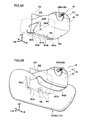
FIG. 2A is perspective view showing an airbag door of a column-mounted knee airbag device according to the first exemplary embodiment of the present invention, as seen prior to deployment. -
FIG. 2B is perspective view showing an airbag door of a column-mounted knee airbag device according to the first exemplary embodiment of the present invention, as seen in the deployed state. -
FIG. 3 is perspective view showing a knee airbag, in a deployed state, of the column-mounted knee airbag device according to the first exemplary embodiment of the present invention. -
FIG. 4 is a partially cut-away back view showing a knee airbag, in a deployed state, of the column-mounted knee airbag device according to the first exemplary embodiment of the present invention. -
FIG. 5 is a partially cut-away side view showing a column-mounted knee airbag device according to a second exemplary embodiment of the present invention. -
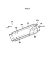
FIG. 6 is a partially cut-away side view showing an inflator and a diffuser of a column-mounted knee airbag device according to the second exemplary embodiment of the present invention. -
FIG. 7 is a partially cut-away side view showing a column-mounted knee airbag device according to a third exemplary embodiment of the present invention. -
FIG. 8A is a perspective view showing an inflator and a diffuser of a column-mounted knee airbag device according to the third exemplary embodiment of the present invention. -
FIG. 8B is a side view showing an inflator and a diffuser of a column-mounted knee airbag device according to the third exemplary embodiment of the present invention. -
FIG. 9A is perspective view of an exemplary modification of an airbag door configuring a column-mounted knee airbag device according to each of the exemplary embodiments of the present invention. -
FIG. 9B is perspective view of an exemplary modification of an airbag door configuring a column-mounted knee airbag device according to each of the exemplary embodiments of the present invention. - Explanation will now be given of a column-mounted
knee airbag device 10 according to a first exemplary embodiment of the present invention, with reference toFIG. 1 to FIG. 4 . Note that the arrow FR, the arrow UP, and the arrow W shown for ease of reference in each of the drawings indicate the front direction (direction of progression), the upward direction, and the width direction of the vehicle to which the column-mountedknee airbag device 10 is applied. Explanation will first be given of the outline configuration of asteering column 12 to which the column-mountedknee airbag device 10 is applied, and explanation will then be given of the column-mountedknee airbag device 10 itself. -
FIG. 1 shows the outline overall configuration of asteering column 12 in a partially cut-away side view. As shown in the figure, thesteering column 12 is configured to include main portions of: a steering columnmain body 14 serving as the steering column of the present invention; acolumn cover 15, covering the rear end of the steering columnmain body 14 in the vehicle front-rear direction; and asteering wheel 20, disposed at a rear end portion of the steering columnmain body 14 in the vehicle front-rear direction. - The
steering column 12 is inserted in a forward tilted state through anopening 24 formed in aninstrument panel 22 so as to face toward the driver's seat. Thesteering column 12 is supported on instrument panel reinforcement (not shown in the figures), spanning across inside theinstrument panel 22 between left and right front pillars, via a tilting andtelescoping drive mechanism 25. - In the assembled state of the
steering column 12 to the vehicle body, thecolumn cover 15 is disposed in a state such that a portion at the front end of thecolumn cover 15 is disposed inside theinstrument panel 22, with the remaining portion of thecolumn cover 15 protrudes out into the cabin C. Thecolumn cover 15 is of an upper and lower two part structure.
Specifically, thecolumn cover 15 is configured in a cylindrical shape overall from a columnupper cover 16 configuring the upper portion of thecolumn cover 15 in the vehicle up-down direction and a columnlower cover 18. - The steering column
main body 14 is equipped with acolumn tube 26 forming a substantially circular cylindrical shape, with a steeringmain shaft 28 rotatably supported in an axial portion of thecolumn tube 26. The steeringmain shaft 28 is divided in the column axial direction into two portions, with anupper side shaft 28A and a lower side shaft (not shown in the figures) connected together by a spline fitting. Theupper side shaft 28A is therefore capable of relative displacement within a specific stroke range in the axial direction with respect to the lower side shaft, and is incapable of relative rotation thereto. Thesteering wheel 20, to which the driver applies a steering force, is fixed to a rear end portion of theupper shaft side 28A with a nut. - The
column tube 26 covering the steeringmain shaft 28 is divided into two portions in the column axial direction (a double-tube structure), with aninner tube 30 disposed at the driver (steering wheel 20) side and anouter tube 32 disposed at the opposite side to that of the driver (the steering gear box side). Theinner tube 30 and theouter tube 32 are connected together by a spline fitting. In thecolumn tube 26 the internal diameter of theouter tube 32 is set bigger than the outer diameter of theinner tube 30. In the event, for example, of a secondary collision of the driver with thesteering wheel 20, thecolumn tube 26 is configured such that theinner tube 30 slides in theouter tube 32 and thecolumn tube 26 collapses, so as to absorb energy from the secondary impact. - In the present exemplary embodiment the
steering column 12 has an electrically operated, tilting andtelescoping drive mechanism 25 disposed at a specific position on thecolumn tube 26 of the steering columnmain body 14. The tilt mechanism of the tilting andtelescoping drive mechanism 25 is a mechanism for adjusting the up-down position (height) of thesteering wheel 20, by rotating thesteering wheel 20 about a rotational axis along the vehicle width direction, a direction orthogonal to the column axial direction. The telescopic mechanism of the tilting andtelescoping drive mechanism 25 is a mechanism for adjusting the position of thesteering wheel 20 in the vehicle front-rear direction, by sliding theinner tube 30 with respect to the outer tube 32 (by extending or retracting the column tube 26) along their axial direction. Known mechanisms can be suitably adopted for the tilting andtelescoping drive mechanism 25, and specific explanation of specific structures thereof will be omitted. - The
instrument panel 22 shown by the solid line inFIG. 1 shows the relative position with respect to the position of thesteering wheel 20 moved to the furthest position toward the front in the vehicle front-rear direction by the tilting andtelescoping drive mechanism 25. Theinstrument panel 22 shown with the two-dot chain line shows the relative position with respect to the position of thesteering wheel 20 moved to the furthest position toward the rear in the vehicle front-rear direction by the tilting andtelescoping drive mechanism 25. The former state, namely the state with thesteering wheel 20 positioned at the limit of movement forward relative to theinstrument panel 22, will be referred to below as the telescopic short state. - In the
above steering column 12, the column-mountedknee airbag device 10 is disposed toward the rear end of the steering columnmain body 14 in the vehicle front-rear direction and below the steering columnmain body 14 in the vehicle up-down direction. The column-mountedknee airbag device 10 is actuated when a frontal impact of the vehicle is detected, or predicted. The column-mountedknee airbag device 10 is configured with main portions including: anairbag module 36 fixed through abracket 34 below theinner tube 30; and anairbag door 38 formed in the columnlower cover 18 configuring a lower portion of thecolumn cover 15. - The
airbag module 36 is equipped with, an inflator 40 that generates gas when actuated, and is also equipped with aknee airbag 42 that is inflated and deployed by gas supplied from the inflator 40, and amodule case 44 accommodating these components. The inflator 40 is disposed substantially parallel to the steering columnmain body 14 so that the longitudinal direction of the inflator 40 is along the vehicle front-rear direction when seen in plan view. The inflator 40 is fixed to themodule case 44 and to thebracket 34 using fastening means 46, formed from stud bolts and nuts. Theairbag module 36 is thereby fixed with respect to theinner tube 30 of the steering columnmain body 14 in the manner stated above, and follows the telescopic operation of thesteering wheel 20. - The
module case 44 in this state is latched to front andrear ribs 50 provided to both end portions of the columnlower cover 18 in the vehicle front-rear direction, and accommodates the inflator 40 and theknee airbag 42 below theinner tube 30. Themodule case 44 may, for example, be configured from a cloth material or the like that is both flexible and soft, or may be configured so as to be relatively rigid, such as from a metal or the like. - Gas ejection holes 48 are formed in a rear end portion, in the vehicle front-rear direction, of the inflator 40 that is fixed to the
inner tube 30. The gas ejection holes 48 are provided respectively at both sides, in the vehicle width direction, of the rear portion of the inflator 40 that gas generated by theinflator 40 is ejected out toward both sides in the vehicle width direction. - As shown in
FIG. 1 , theinflator 40 is disposed so that, in the telescopic short state, the gas ejection holes 48 are positioned in the vehicle front-rear direction at the rear side of a vehicle front-rear direction rearward-facingdecorative surface 22A of the instrument panel 22 (the opposite face of theinstrument panel 22 to that facing the knee airbag 42). Namely, the gas ejection holes 48 are configured so as to always be positioned in the vehicle front-rear direction further to the rear than thedecorative surface 22A, independent of the front-rear positioning of thesteering wheel 20. - The
knee airbag 42 is configured to accommodate at least a portion of the inflator 40 that includes the location formed with the gas ejection holes 48, such that theknee airbag 42 inflates and deploys when gas from the inflator 40 is supplied out from the gas ejection holes 48. The gas ejection holes 48 therefore correspond to the gas supply openings of the present invention. Prior to actuation of the column-mountedknee airbag device 10, theknee airbag 42 is disposed in a folded state inside themodule case 44 between the columnlower cover 18 and thebracket 34. Theknee airbag 42 is folded, for example, with bellows folding, roll folding, cactus folding, or a combination using at least some of these. - When in receipt of gas supplied from the inflator 40, the
knee airbag 42 deploys between thedecorative surface 22A of theinstrument panel 22 and both knees K of the driver P, as shown by the two-dot chain line inFIG. 1 , protecting both knees K thereby. Namely, theknee airbag 42 is configured so as to arrest both knees K (suppress forward movement thereof) while supported with thedecorative surface 22A of theinstrument panel 22 acting as a reaction surface. - Furthermore, with respect to the deployed state of the
knee airbag 42, the deployed state is such that theknee airbag 42 is deployed as shown inFIG. 2B andFIG. 3 . Specifically, as shown inFIG. 3 , a pair of upper and lower straps, i.e., anupper strap 52 and alower strap 54, are provided internally to theknee airbag 42 so as to be deployed separated from each other in the vehicle up-down direction. Theupper strap 52 and thelower strap 54 are each configured from a cloth material formed in a substantially rectangular shape with the longitudinal direction thereof along the vehicle width direction when seen in plan view. A width a of theupper strap 52 along the vehicle front-rear direction is greater than a width b of thelower strap 54 along the vehicle front-rear direction (a > b). Theknee airbag 42 is thereby configured, as shown inFIG. 1 andFIG. 3 , so as to have a thickness in the vehicle front-rear direction in the deployed state that is greater at the upper portion than at the lower portion of theknee airbag 42. - In the column-mounted
knee airbag device 10, as shown inFIG. 4 , in the deployed state of the knee airbag 42 (the completely deployed state without load applied thereto) the inflator 40 (the gas ejection holes 48) is positioned in theknee airbag 42 within acentral bag portion 42A between theupper strap 52 and thelower strap 54. In this state the gas ejection holes 48 of the inflator 40 are disposed in thecentral bag portion 42A of the deployedstate knee airbag 42 so as to be positioned more in the vicinity of theupper strap 52 than thelower strap 54. - An
upper bag portion 42B forming a portion above thecentral bag portion 42A of theknee airbag 42, and alower bag portion 42C forming a portion below thecentral bag portion 42A are, as shown in arrow G ofFIG. 4 , supplied by gas that passes around the end portions in the longitudinal direction of theupper strap 52 and thelower strap 54, so as to be inflated and deployed thereby. Theknee airbag 42 according to the present exemplary embodiment is configured such that the length along the vehicle width direction at theupper bag portion 42B side is shorter than at thelower bag portion 42C side when viewed from the rear. - As shown in
FIG. 2A ,specific tear lines 56 are provided to theairbag door 38 on the inside of the columnlower cover 18, so as to break when the bag inflation pressure is of a specific amount or greater, opening theairbag door 38. In the present exemplary embodiment the tear lines 56 are formed as thinned portions of groove shaped recesses. - In further explanation of the
airbag door 38 according to the present exemplary embodiment, theairbag door 38 includes afront door portion 38A, arear door portion 38B, aleft door portion 38C, and aright door portion 38D, as shown inFIG. 2B . Thefront door portion 38A has edges of substantially a U- shape, as shown inFIG. 2A , formed by the tear lines 56 which include a firstvehicle width line 56A formed along the vehicle width direction at a bottom wall portion of the columnlower cover 18, and a pair of bottom front-rear lines 56B that each extend respectively frontward from the two ends of the firstvehicle width line 56A. Thefront door portion 38A hinges with a portion at the front end of the pair of bottom front-rear lines 56B acting as the hinge portion, so as to open by folding back toward the front below the columnlower cover 18, as shown inFIG. 2B . Therear door portion 38B, as shown inFIG. 2A , has the firstvehicle width line 56A, a secondvehicle width line 56C formed substantially parallel to, and at the rear of the firstvehicle width line 56A, and a side inverted-U-shaped line 56D formed in the left wall of the columnlower cover 18 and connecting between the left ends of the firstvehicle width line 56A and the secondvehicle width line 56C. Therear door portion 38B has an edge portion surrounded by a non-illustrated right line that is formed in the right had wall extending substantially parallel to and above the right ends of the firstvehicle width line 56A and the secondvehicle width line 56C. Therear door portion 38B opens so as to fold back to toward the right and top, as shown inFIG. 2B . Theleft door portion 38C, as shown inFIG. 2A , is formed in substantially a U-shape surrounded by edge portions of the bottom front-rear line 56B on the left, atop line 56E that is formed in a portion of the left wall of the columnlower cover 18 substantially parallel to the bottom front-rear line 56B on the left, and the side inverted-U-shaped line 56D. Theleft door portion 38C opens with a portion between the front ends of the bottom front-rear lines 56B and thetop line 56E acting as a hinge portion, so as to open by folding forward at the left outside of the columnlower cover 18, as shown inFIG. 2B . Theright door portion 38D, while details of the tear lines 56 are not shown in the drawing, is formed so as to be left-right symmetrical to theleft door portion 38C, and so as to open by folding forward at the right outside of the columnlower cover 18, as shown inFIG. 2B . - The
airbag door 38, as explained above, is provided with at least therear door portion 38B (the firstvehicle width line 56A, the side inverted-U-shaped line 56D) provided in a position further to the rear than thedecorative surface 22A of theinstrument panel 22 when in the telescopic short state. For any portions of theairbag door 38 that may be positioned further to the front in the vehicle front-rear direction than thedecorative surface 22A, during the opening process the portion of theairbag door 38 that contacts the edge portion of theopening 24 acts in place of the above hinge portions, so as to open. - In the column-mounted
knee airbag device 10, the inflator 40 actuation timing is controlled through an airbag ECU as a non-illustrated control means. The airbag ECU is configured, for example, so as to actuate the inflator 40 when a vehicle frontal impact is detected, or predicted, for a vehicle to which the column-mountedknee airbag device 10 has been applied, based on a signal from an frontal impact sensor. - Explanation will now be given of the operation of the first exemplary embodiment.
- In the column-mounted
knee airbag device 10 configured as described above, the airbag ECU that, based on a signal from an impact sensor, has detected, or predicted, a frontal impact of the vehicle to which the column-mountedknee airbag device 10 has been applied, actuates theinflator 40. When this occurs a large volume of gas is generated by theinflator 40, and this gas is ejected in a vehicle width direction from the gas ejection holes 48 of the inflator 40 and supplied into theknee airbag 42. Theknee airbag 42 is inflated and deployed thereby, and when the deployment pressure of theknee airbag 42 acting on theairbag door 38 reaches a specific value, the columnlower cover 18 breaks along the tear lines 56 as shown inFIG. 2B , and theairbag door 38 opens. - The
knee airbag 42 inflates and deploys toward both sides in the vehicle width direction (substantially along thedecorative surface 22A of the instrument panel 22) below thesteering column 12 in the vehicle up-down direction. The inflated and deployedknee airbag 42 thereby arrests and protects both knees K, with theknee airbag 42 interposed between thedecorative surface 22A (reaction surface) of theinstrument panel 22 and both knees K of the driver P. - In the telescopic short state of the column-mounted
knee airbag device 10, the gas ejection holes 48 of the inflator 40 are positioned to the rear side in the vehicle front-rear direction with respect to thedecorative surface 22A of theinstrument panel 22. In the present column-mountedknee airbag device 10, gas can therefore be supplied to theknee airbag 42 at the rear side (knee K side) with respect to thedecorative surface 22A of theinstrument panel 22. Thereby, deployment initiation does not occur when the knee airbag 42 (a portion thereof) is at the inside of the instrument panel when the column-mountedknee airbag device 10 is actuated in the telescopic short state. Consequently, theknee airbag 42 can be rapidly deployed in front of the knees of the driver (between the knees K and thedecorative surface 22A of the instrument panel 22). - In this manner, in the column-mounted
knee airbag device 10 according to the first exemplary embodiment, theknee airbag 42 can be appropriately deployed even if the forward-rear position of theinner tube 30 of thecolumn tube 26 has changed due to the telescopic function. In other words, the present column-mountedknee airbag device 10 can be appropriately deployed independently of changes in the front-rear position of theairbag module 36 due to the tilting andtelescoping drive mechanism 25. - In the column-mounted
knee airbag device 10, the gas ejection holes 48 are also provided at a rear end portion in the vehicle front-rear direction of the inflator 40 that has its longitudinal direction along the vehicle front-rear direction. A configuration in which the gas ejection holes 48 are disposed to the rear side in the vehicle front-rear direction of thedecorative surface 22A, even when in the telescopic short state, can therefore be realized using a simple structure. The inflator 40 that has its longitudinal direction along the vehicle front-rear direction, i.e. is longitudinally mounted, has the merit that when applied to asteering column 12 that is short in the vehicle front-rear direction, the inflator 40 can be disposed so as to have no interference with non-illustrated steering lock devices or the like. - In addition, the column-mounted
knee airbag device 10 is configured with the gas ejection holes 48 positioned in thecentral bag portion 42A of theknee airbag 42 so as to be more in the vicinity of theupper strap 52 than in the vicinity of thelower strap 54. Consequently, more rapid deployment can be made of the top portion of theknee airbag 42 deployed in front of the knees K of an average framed driver or a large framed driver. - Explanation will now be given of other exemplary embodiments of the present invention. Components and portions that are fundamentally the same as the above first exemplary embodiment or a aforementioned configuration are allocated the same reference numerals as those of the first exemplary embodiment or the aforementioned configuration, and explanation and illustration thereof is sometimes omitted.
- A column-mounted
knee airbag device 60 according to a second exemplary embodiment is shown as a partially cut-away side view inFIG. 5 . As shown in this figure, the column-mountedknee airbag device 60 differs from the column-mountedknee airbag device 10 of the first exemplary embodiment in being equipped with an inflator 62 that is provided with gas ejection holes 48 at a front end portion, instead of the inflator 40 provided with gas ejection holes 48 at a rear end portion. - Specifically, as shown in
FIG. 6 , the outer peripheral side of a portion of the inflator 62, including the locations disposed with the gas ejection holes 48 opened in the outer peripheral face of the inflator 62, is covered by adiffuser 64 serving as a flow adjusting member formed in a cylindrical shape. The inflator 62 and thediffuser 64 are fixed together in a gas sealed state at a portion at the front end in the vehicle front-rear direction (further forward than the gas ejection holes 48), and at a portion at the rear end in the vehicle front-rear direction, such that there is a gas path formed therebetween. In the column-mountedknee airbag device 60, gas supply holes 65 are formed as gas supply openings in the vicinity of the rear end of thediffuser 64, namely directly in front of portion that is fixed toinflator 62 at the rear side of thediffuser 64. - The gas supply holes 65 are formed at both sides of the
diffuser 64 in the vehicle width direction so as to face in the vehicle width direction. Namely, in the column-mountedknee airbag device 60 the gas of the inflator 62 ejected from the gas ejection holes 48 is guided by the diffuser 64 (between thediffuser 64 and the inflator 62) to reach a portion at the rear in the vehicle front-rear direction, such that gas is ejected out to both sides in the vehicle width direction from the gas supply holes 65 at the left and the right. - The
knee airbag 42 accommodates at least the portion of thediffuser 64 including the forming locations of the gas supply holes 65, such that theknee airbag 42 is supplied by the inflator 62 with gas from the gas supply holes 65, and thereby inflated and deployed. Consequently, the gas supply holes 65 correspond to the gas supply openings of the present invention. Non-illustrated stud bolts configuring a fastening means 46 are provide to thediffuser 64. The other parts of the configuration of the column-mountedknee airbag device 60 are the same as the corresponding parts of the configuration of the column-mountedknee airbag device 10. - Consequently, fundamentally the same effects can also be obtained with the column-mounted
knee airbag device 60 according to the second exemplary embodiment, by operation in a similar manner to that of the column-mountedknee airbag device 10 according to the first exemplary embodiment. - In addition, in the column-mounted
knee airbag device 60, since the inflator 62 can be disposed such that the position of the gas ejection holes 48 are at the front end side of the inflator 62 in the vehicle front-rear direction, as shown inFIG. 6 , a connector portion that is the wiring connection portion of the inflator 62, can be positioned at the rear end of the inflator 62 in the vehicle front-rear direction. Therefore, in the column-mountedknee airbag device 60, when performing a wiring connection operation of the inflator 62, an opposingconnector 66 is simply inserted into aconnector portion 62A of the inflator 62 facing toward the cabin C, and the wiring connection operation is easy. Also, for example, sometimes configuration is made with theconnector portion 62A positioned at the front side in the vehicle front-rear direction, with sub-wiring extending toward the rear from theconnector portion 62A of the inflator 62 employed in order to improve productivity of the connecting operation. In the column-mountedknee airbag device 60, such sub-wiring can be made unnecessary (the wiring connection operation can be made easy without reliance on sub-wiring). - A column-mounted
knee airbag device 70 according to a third exemplary embodiment of the present invention is shown as a partially cut-away side view inFIG. 7 . As shown in the figure, the column-mountedknee airbag device 70 differs from the column-mountedknee airbag device 10 of the first exemplary embodiment in being equipped with an inflator 72 with longitudinal direction along the vehicle width direction, instead of the inflator 40 having its longitudinal direction along the vehicle front-rear direction. - Specifically, as shown in
FIG. 8A and 8B , the outer peripheral side of a portion of the inflator 72, including the locations disposed with the gas ejection holes 48 opened in the outer peripheral face of the inflator 72, is covered by adiffuser 74 serving as a flow adjusting member formed in a cylindrical shape. Namely, thediffuser 74 covers the gas ejection holes 48 (the entire area where the gas ejection holes 48 are disposed) of the disposed locations thereof) that are formed at one end side in the longitudinal direction of the inflator 72, and both ends of thediffuser 74 in the vehicle width direction areopen ends 74A. The column-mountedknee airbag device 70 is thereby configured such that the gas ejected from the gas ejection holes 48 is adjusted in flow by thediffuser 74 so as to flow along the vehicle width direction, and is ejected from the open ends 74A at the left and right respectively. - The
knee airbag 42 accommodates the inflator 72 and thediffuser 74 in their entirety, and gas supplied by the inflator 72 from the open ends 74A of thediffuser 74 inflates and deploys theknee airbag 42. Consequently, each of the open ends 74A of thediffuser 74 correspond to the gas supply opening of the present invention. It should be noted that as shown inFIG. 8B ,stud bolts 46A, configuring the fastening means 46, are provided to thediffuser 74. Thediffuser 74 is provided with crimpedportions 74B at plural locations around the circumference of thediffuser 74, thecrimped portions 74B making contact with the outer periphery of theinflator 72. Thediffuser 74 is fixed to the inflator 72 by the crimpedportions 74B. Other parts of the configuration of the column-mountedknee airbag device 70 are the same as the corresponding parts of the configuration of the column-mountedknee airbag device 10. - Consequently, fundamentally the same effects can also be obtained by with the column-mounted
knee airbag device 70 according to the third exemplary embodiment, by operation in a similar manner to that of the column-mountedknee airbag device 10 according to the first exemplary embodiment. - It should be noted that while in each of the above exemplary embodiments examples given have been equipped with the
airbag door 38 configuration, present invention is not limited thereto. For example, configuration may be made equipped with anairbag door 80 according to a preferable exemplary modification, as shown inFIG. 9A and 9B . Theairbag door 80 has afront door portion 80A, aleft door portion 80C, and aright door portion 80D configured substantially the same as thefront door portion 38A, theleft door portion 38C, and theright door portion 38D. Theairbag door 80, however, has arear door portion 80B that deploys by folding back below the columnlower cover 18 substantially towards the rear. Therear door portion 80B of theairbag door 80 can be configured without provision of the secondvehicle width line 56C, by forming a side inverted-U-shaped line 56D and symmetrical side inverted-U-shaped line in portions of the side walls of the columnlower cover 18. In such a configuration therear door portion 80B opens with a portion between the front bottom ends of the left and right side inverted-U-shaped lines 56D (the portion corresponding to the disposed position of the secondvehicle width line 56C) acting as a hinge. - The airbag door in the present invention is not also not limited to the four-part structures of the
airbag doors lower cover 18, instead of the structure in which the columnlower cover 18 is integrally formed. It should be noted that, independent of which airbag door embodiment is adopted, configuration is preferably made with a door portion opening at the rear side of thedecorative surface 22A of theinstrument panel 22, in the vehicle front-rear direction, like therear door portion 38B.
Claims (7)
- A column-mounted knee airbag device comprising:a knee airbag used for protecting the knees of a driver, the knee airbag being folded inside a column cover that covers a steering column having a telescopic function, the knee airbag opening an airbag door provided in the column cover by deployment pressure when supplied with gas and deploying between an instrument panel and the knees of the driver; andan inflator installed at the inside of the column cover, the inflator being actuated and generating gas when a vehicle impact is detected or predicted,wherein a gas supply opening for supplying gas from the inflator to the knee airbag is disposed in a position further to the rear than the instrument panel in the vehicle front-rear direction, when viewed from the side with the steering column in a state positioned furthest to the front in the vehicle front-rear direction due to the telescopic function.
- The column-mounted knee airbag device of claim 1, wherein the gas supply opening is disposed inside the knee airbag such that gas is ejected toward both sides in the vehicle width direction.
- The column-mounted knee airbag device of claim 1 or claim 2, wherein:the longitudinal direction of the inflator is along the vehicle front-rear direction; andthe gas supply opening is a gas ejection hole provided at a rear end portion of the inflator in the vehicle front-rear direction, opening toward the vehicle width direction.
- The column-mounted knee airbag device of claim 1 or claim 2, wherein:the longitudinal direction of the inflator is along the vehicle front-rear direction and a gas ejection hole is provided at a front end side of the inflator in the vehicle front-rear direction;a diffuser for guiding gas from the gas ejection hole to the knee airbag is fixed to the inflator; andthe gas supply opening is a gas supply hole provided at a rear end portion of the diffuser in the vehicle front-rear direction, opening toward the vehicle width direction.
- The column-mounted knee airbag device of claim 4, wherein the diffuser covers the inflator from an outer peripheral side so as to guide gas from the gas ejection hole to the gas supply hole through a space formed between the diffuser and an outer peripheral face of the
- The column-mounted knee airbag device of claim 1 or claim 2, wherein:the longitudinal direction of the inflator is along the vehicle width direction, a gas ejection hole is opened in an outer peripheral face of the inflator and the inflator is covered from the outer peripheral side by a diffuser for guiding gas from the gas ejection hole to the knee airbag; andthe gas supply openings are open ends formed at both sides in the vehicle width direction of a space between an inner peripheral face of the diffuser and the outer peripheral face of the inflator.
- The column-mounted knee airbag device of any one of claim 1 to claim 6, wherein:the knee airbag has a pair of upper and lower straps for restricting the thickness of the knee airbag in the vehicle front-rear direction when in the deployed state; andthe gas supply opening is disposed inside the knee airbag between the pair of straps so as to be in the vicinity of the upper strap of the pair of straps when the knee airbag is in the deployed state.
Applications Claiming Priority (2)
| Application Number | Priority Date | Filing Date | Title |
|---|---|---|---|
| JP2008062662A JP4420121B2 (en) | 2008-03-12 | 2008-03-12 | Knee airbag device with column |
| PCT/JP2009/052638 WO2009113365A1 (en) | 2008-03-12 | 2009-02-17 | Knee airbag device with column |
Publications (3)
| Publication Number | Publication Date |
|---|---|
| EP2253514A1 true EP2253514A1 (en) | 2010-11-24 |
| EP2253514A4 EP2253514A4 (en) | 2012-10-24 |
| EP2253514B1 EP2253514B1 (en) | 2014-01-15 |
Family
ID=41065037
Family Applications (1)
| Application Number | Title | Priority Date | Filing Date |
|---|---|---|---|
| EP09720013.3A Active EP2253514B1 (en) | 2008-03-12 | 2009-02-17 | Knee airbag device with column |
Country Status (5)
| Country | Link |
|---|---|
| US (1) | US8220828B2 (en) |
| EP (1) | EP2253514B1 (en) |
| JP (1) | JP4420121B2 (en) |
| CN (1) | CN101678808B (en) |
| WO (1) | WO2009113365A1 (en) |
Families Citing this family (11)
| Publication number | Priority date | Publication date | Assignee | Title |
|---|---|---|---|---|
| JP4379463B2 (en) * | 2006-10-31 | 2009-12-09 | トヨタ自動車株式会社 | Knee airbag device with column |
| JP4591574B2 (en) * | 2008-08-06 | 2010-12-01 | トヨタ自動車株式会社 | Knee airbag device for vehicle |
| DE102010030194B4 (en) * | 2010-06-17 | 2018-06-07 | Bayerische Motoren Werke Aktiengesellschaft | Knee airbag arrangement for vehicles |
| WO2013054397A1 (en) * | 2011-10-11 | 2013-04-18 | トヨタ自動車株式会社 | Knee airbag device for vehicle |
| KR101627125B1 (en) * | 2013-04-19 | 2016-06-14 | 아우토리브 디벨롭먼트 아베 | Mounting knee airbag apparatus and method of folding airbag thereof |
| JP6413934B2 (en) * | 2015-06-03 | 2018-10-31 | マツダ株式会社 | Arrangement structure of occupant protection device |
| JP6911629B2 (en) * | 2017-08-21 | 2021-07-28 | トヨタ自動車株式会社 | Vehicle knee airbag device and knee airbag folding method |
| JP7087814B2 (en) * | 2018-08-10 | 2022-06-21 | トヨタ自動車株式会社 | Front structure of the passenger compartment |
| DE102019208417A1 (en) * | 2019-06-11 | 2020-12-17 | Audi Ag | Leg protection device for an occupant protection system of a vehicle |
| DE102019121361A1 (en) * | 2019-08-07 | 2021-02-11 | Bayerische Motoren Werke Aktiengesellschaft | Steering column unit of a vehicle with impact pads |
| KR20250171044A (en) * | 2024-05-29 | 2025-12-08 | 현대모비스 주식회사 | Protector for inflater |
Family Cites Families (28)
| Publication number | Priority date | Publication date | Assignee | Title |
|---|---|---|---|---|
| DE4418628A1 (en) * | 1994-05-27 | 1995-11-30 | Trw Repa Gmbh | Occupant restraint system for the driver's side in a vehicle |
| JP4198201B2 (en) * | 1995-06-02 | 2008-12-17 | 株式会社ルネサステクノロジ | Semiconductor device |
| JPH09104317A (en) | 1995-10-09 | 1997-04-22 | Mitsubishi Motors Corp | Occupant protection device |
| DE29807424U1 (en) * | 1998-04-23 | 1998-08-27 | Trw Repa Gmbh | Knee protection device for vehicle occupants |
| US6170871B1 (en) * | 1998-06-24 | 2001-01-09 | Breed Automotive Technology, Inc. | Inflatable trim panel assembly for safety restraint systems |
| US6299200B1 (en) * | 2000-07-18 | 2001-10-09 | Trw Vehicle Safety Systems Inc. | Side impact air bag module with shroud |
| JP2002037003A (en) | 2000-07-21 | 2002-02-06 | Toyoda Gosei Co Ltd | Air bag device for protecting knee |
| US6945557B2 (en) | 2001-11-09 | 2005-09-20 | Toyoda Gosei Co., Ltd. | Knee protecting airbag device |
| US6752417B2 (en) * | 2001-05-21 | 2004-06-22 | Toyoda Gosei Co., Ltd. | Knee protecting airbag device |
| JP3807317B2 (en) * | 2002-01-31 | 2006-08-09 | 豊田合成株式会社 | Air bag device for knee protection |
| DE10131286C1 (en) * | 2001-06-28 | 2002-11-21 | Breed Automotive Tech | Gas feed line, for automobile airbag module, has internal flow conduction element for rotation of linear flow through gas feed line |
| JP2003054352A (en) * | 2001-08-10 | 2003-02-26 | Takata Corp | Device for protecting leg part of occupant |
| DE20117794U1 (en) * | 2001-10-31 | 2002-05-29 | Trw Repa Gmbh | Knee restraint for a driver |
| JP2005053440A (en) * | 2003-08-07 | 2005-03-03 | Daicel Chem Ind Ltd | Inflator |
| EP1531098B1 (en) * | 2003-11-13 | 2018-09-19 | Ford Global Technologies, LLC, A subsidary of Ford Motor Company | Airbag |
| US7377541B2 (en) * | 2004-01-14 | 2008-05-27 | Takata Corporation | Leg-protection device for vehicle occupant |
| JP4379410B2 (en) | 2005-11-09 | 2009-12-09 | トヨタ自動車株式会社 | Air bag device for knee protection |
| US7942440B2 (en) * | 2005-12-22 | 2011-05-17 | Autoliv Asp, Inc. | Channel and diffuser airbag |
| JP2007203937A (en) | 2006-02-03 | 2007-08-16 | Toyoda Gosei Co Ltd | Knee protecting airbag device |
| JP2007276522A (en) * | 2006-04-03 | 2007-10-25 | Toyoda Gosei Co Ltd | Side airbag device |
| JP4432932B2 (en) * | 2006-05-09 | 2010-03-17 | トヨタ自動車株式会社 | Vehicle knee airbag device and vehicle knee airbag deployment method |
| JP4386910B2 (en) * | 2006-09-29 | 2009-12-16 | 豊田合成株式会社 | Air bag device for knee protection |
| JP4408884B2 (en) | 2006-10-31 | 2010-02-03 | 豊田合成株式会社 | Air bag device for knee protection |
| JP4379463B2 (en) | 2006-10-31 | 2009-12-09 | トヨタ自動車株式会社 | Knee airbag device with column |
| JP4235221B2 (en) | 2006-11-02 | 2009-03-11 | トヨタ自動車株式会社 | Knee airbag device with column |
| JP4235224B2 (en) | 2006-11-09 | 2009-03-11 | トヨタ自動車株式会社 | Knee airbag device with column |
| JP2008222111A (en) * | 2007-03-14 | 2008-09-25 | Toyoda Gosei Co Ltd | Air bag device for knee protection |
| WO2009029203A1 (en) * | 2007-08-27 | 2009-03-05 | Key Safety Systems, Inc. | Knee airbag module |
-
2008
- 2008-03-12 JP JP2008062662A patent/JP4420121B2/en active Active
-
2009
- 2009-02-17 WO PCT/JP2009/052638 patent/WO2009113365A1/en not_active Ceased
- 2009-02-17 US US12/530,677 patent/US8220828B2/en active Active
- 2009-02-17 CN CN2009800001162A patent/CN101678808B/en active Active
- 2009-02-17 EP EP09720013.3A patent/EP2253514B1/en active Active
Also Published As
| Publication number | Publication date |
|---|---|
| CN101678808A (en) | 2010-03-24 |
| EP2253514A4 (en) | 2012-10-24 |
| EP2253514B1 (en) | 2014-01-15 |
| US8220828B2 (en) | 2012-07-17 |
| WO2009113365A1 (en) | 2009-09-17 |
| JP4420121B2 (en) | 2010-02-24 |
| JP2009214809A (en) | 2009-09-24 |
| US20100295279A1 (en) | 2010-11-25 |
| CN101678808B (en) | 2012-06-27 |
Similar Documents
| Publication | Publication Date | Title |
|---|---|---|
| EP2253514B1 (en) | Knee airbag device with column | |
| JP4477648B2 (en) | Steering column device with knee airbag device with column | |
| JP4210700B2 (en) | Knee airbag device with column | |
| EP3900985B1 (en) | Side airbag device, vehicle seat provided with same, and method for manufacturing side airbag device | |
| JP4332183B2 (en) | Knee airbag device with column and method of assembling a steering column having the same to a vehicle | |
| US7681908B2 (en) | Knee airbag device | |
| CN110431052B (en) | Occupant protection device | |
| EP3738840B1 (en) | Occupant protection apparatus | |
| WO2019026538A1 (en) | Occupant protection device | |
| WO2008053664A1 (en) | Knee air bag with column | |
| JP5060351B2 (en) | Knee airbag device with column | |
| EP1944201B1 (en) | Occupant leg part restraining apparatus and retainer | |
| JP4053385B2 (en) | Air bag device for knee protection | |
| JP4053384B2 (en) | Air bag device for knee protection | |
| JP4760682B2 (en) | Knee airbag device with column | |
| JP4853417B2 (en) | Knee airbag device with column | |
| JP2006088923A (en) | Airbag, and non-occupant crash protection device | |
| JP4760698B2 (en) | Knee airbag device with column | |
| JP7816989B2 (en) | Rear seat side airbag system | |
| JP4900112B2 (en) | Knee airbag device with column | |
| JP4935686B2 (en) | Knee airbag device with column | |
| JP2009184602A (en) | Knee airbag device with column |
Legal Events
| Date | Code | Title | Description |
|---|---|---|---|
| PUAI | Public reference made under article 153(3) epc to a published international application that has entered the european phase |
Free format text: ORIGINAL CODE: 0009012 |
|
| 17P | Request for examination filed |
Effective date: 20090911 |
|
| AK | Designated contracting states |
Kind code of ref document: A1 Designated state(s): AT BE BG CH CY CZ DE DK EE ES FI FR GB GR HR HU IE IS IT LI LT LU LV MC MK MT NL NO PL PT RO SE SI SK TR |
|
| AX | Request for extension of the european patent |
Extension state: AL BA RS |
|
| DAX | Request for extension of the european patent (deleted) | ||
| A4 | Supplementary search report drawn up and despatched |
Effective date: 20120920 |
|
| RIC1 | Information provided on ipc code assigned before grant |
Ipc: B60R 21/20 20110101AFI20120914BHEP Ipc: B62D 1/18 20060101ALI20120914BHEP Ipc: B62D 1/16 20060101ALI20120914BHEP |
|
| RAP1 | Party data changed (applicant data changed or rights of an application transferred) |
Owner name: TOYOTA JIDOSHA KABUSHIKI KAISHA |
|
| GRAP | Despatch of communication of intention to grant a patent |
Free format text: ORIGINAL CODE: EPIDOSNIGR1 |
|
| INTG | Intention to grant announced |
Effective date: 20130809 |
|
| GRAS | Grant fee paid |
Free format text: ORIGINAL CODE: EPIDOSNIGR3 |
|
| GRAA | (expected) grant |
Free format text: ORIGINAL CODE: 0009210 |
|
| RIN1 | Information on inventor provided before grant (corrected) |
Inventor name: SANADA, AKIYOSHI Inventor name: FUKAWATASE, OSAMU |
|
| AK | Designated contracting states |
Kind code of ref document: B1 Designated state(s): AT BE BG CH CY CZ DE DK EE ES FI FR GB GR HR HU IE IS IT LI LT LU LV MC MK MT NL NO PL PT RO SE SI SK TR |
|
| REG | Reference to a national code |
Ref country code: CH Ref legal event code: EP Ref country code: GB Ref legal event code: FG4D |
|
| REG | Reference to a national code |
Ref country code: AT Ref legal event code: REF Ref document number: 649673 Country of ref document: AT Kind code of ref document: T Effective date: 20140215 |
|
| REG | Reference to a national code |
Ref country code: DE Ref legal event code: R096 Ref document number: 602009021441 Country of ref document: DE Effective date: 20140220 |
|
| REG | Reference to a national code |
Ref country code: IE Ref legal event code: FG4D |
|
| REG | Reference to a national code |
Ref country code: NL Ref legal event code: VDEP Effective date: 20140115 |
|
| REG | Reference to a national code |
Ref country code: AT Ref legal event code: MK05 Ref document number: 649673 Country of ref document: AT Kind code of ref document: T Effective date: 20140115 |
|
| REG | Reference to a national code |
Ref country code: LT Ref legal event code: MG4D |
|
| PG25 | Lapsed in a contracting state [announced via postgrant information from national office to epo] |
Ref country code: LT Free format text: LAPSE BECAUSE OF FAILURE TO SUBMIT A TRANSLATION OF THE DESCRIPTION OR TO PAY THE FEE WITHIN THE PRESCRIBED TIME-LIMIT Effective date: 20140115 Ref country code: NO Free format text: LAPSE BECAUSE OF FAILURE TO SUBMIT A TRANSLATION OF THE DESCRIPTION OR TO PAY THE FEE WITHIN THE PRESCRIBED TIME-LIMIT Effective date: 20140415 Ref country code: IS Free format text: LAPSE BECAUSE OF FAILURE TO SUBMIT A TRANSLATION OF THE DESCRIPTION OR TO PAY THE FEE WITHIN THE PRESCRIBED TIME-LIMIT Effective date: 20140515 |
|
| PG25 | Lapsed in a contracting state [announced via postgrant information from national office to epo] |
Ref country code: ES Free format text: LAPSE BECAUSE OF FAILURE TO SUBMIT A TRANSLATION OF THE DESCRIPTION OR TO PAY THE FEE WITHIN THE PRESCRIBED TIME-LIMIT Effective date: 20140115 Ref country code: NL Free format text: LAPSE BECAUSE OF FAILURE TO SUBMIT A TRANSLATION OF THE DESCRIPTION OR TO PAY THE FEE WITHIN THE PRESCRIBED TIME-LIMIT Effective date: 20140115 Ref country code: CY Free format text: LAPSE BECAUSE OF FAILURE TO SUBMIT A TRANSLATION OF THE DESCRIPTION OR TO PAY THE FEE WITHIN THE PRESCRIBED TIME-LIMIT Effective date: 20140115 Ref country code: AT Free format text: LAPSE BECAUSE OF FAILURE TO SUBMIT A TRANSLATION OF THE DESCRIPTION OR TO PAY THE FEE WITHIN THE PRESCRIBED TIME-LIMIT Effective date: 20140115 Ref country code: PT Free format text: LAPSE BECAUSE OF FAILURE TO SUBMIT A TRANSLATION OF THE DESCRIPTION OR TO PAY THE FEE WITHIN THE PRESCRIBED TIME-LIMIT Effective date: 20140515 Ref country code: SE Free format text: LAPSE BECAUSE OF FAILURE TO SUBMIT A TRANSLATION OF THE DESCRIPTION OR TO PAY THE FEE WITHIN THE PRESCRIBED TIME-LIMIT Effective date: 20140115 Ref country code: FI Free format text: LAPSE BECAUSE OF FAILURE TO SUBMIT A TRANSLATION OF THE DESCRIPTION OR TO PAY THE FEE WITHIN THE PRESCRIBED TIME-LIMIT Effective date: 20140115 |
|
| PG25 | Lapsed in a contracting state [announced via postgrant information from national office to epo] |
Ref country code: HR Free format text: LAPSE BECAUSE OF FAILURE TO SUBMIT A TRANSLATION OF THE DESCRIPTION OR TO PAY THE FEE WITHIN THE PRESCRIBED TIME-LIMIT Effective date: 20140115 Ref country code: BE Free format text: LAPSE BECAUSE OF FAILURE TO SUBMIT A TRANSLATION OF THE DESCRIPTION OR TO PAY THE FEE WITHIN THE PRESCRIBED TIME-LIMIT Effective date: 20140115 Ref country code: LV Free format text: LAPSE BECAUSE OF FAILURE TO SUBMIT A TRANSLATION OF THE DESCRIPTION OR TO PAY THE FEE WITHIN THE PRESCRIBED TIME-LIMIT Effective date: 20140115 |
|
| REG | Reference to a national code |
Ref country code: CH Ref legal event code: PL |
|
| REG | Reference to a national code |
Ref country code: DE Ref legal event code: R097 Ref document number: 602009021441 Country of ref document: DE |
|
| PG25 | Lapsed in a contracting state [announced via postgrant information from national office to epo] |
Ref country code: EE Free format text: LAPSE BECAUSE OF FAILURE TO SUBMIT A TRANSLATION OF THE DESCRIPTION OR TO PAY THE FEE WITHIN THE PRESCRIBED TIME-LIMIT Effective date: 20140115 Ref country code: LI Free format text: LAPSE BECAUSE OF NON-PAYMENT OF DUE FEES Effective date: 20140228 Ref country code: RO Free format text: LAPSE BECAUSE OF FAILURE TO SUBMIT A TRANSLATION OF THE DESCRIPTION OR TO PAY THE FEE WITHIN THE PRESCRIBED TIME-LIMIT Effective date: 20140115 Ref country code: CZ Free format text: LAPSE BECAUSE OF FAILURE TO SUBMIT A TRANSLATION OF THE DESCRIPTION OR TO PAY THE FEE WITHIN THE PRESCRIBED TIME-LIMIT Effective date: 20140115 Ref country code: DK Free format text: LAPSE BECAUSE OF FAILURE TO SUBMIT A TRANSLATION OF THE DESCRIPTION OR TO PAY THE FEE WITHIN THE PRESCRIBED TIME-LIMIT Effective date: 20140115 Ref country code: MC Free format text: LAPSE BECAUSE OF FAILURE TO SUBMIT A TRANSLATION OF THE DESCRIPTION OR TO PAY THE FEE WITHIN THE PRESCRIBED TIME-LIMIT Effective date: 20140115 Ref country code: CH Free format text: LAPSE BECAUSE OF NON-PAYMENT OF DUE FEES Effective date: 20140228 |
|
| REG | Reference to a national code |
Ref country code: DE Ref legal event code: R084 Ref document number: 602009021441 Country of ref document: DE |
|
| PLBE | No opposition filed within time limit |
Free format text: ORIGINAL CODE: 0009261 |
|
| STAA | Information on the status of an ep patent application or granted ep patent |
Free format text: STATUS: NO OPPOSITION FILED WITHIN TIME LIMIT |
|
| PG25 | Lapsed in a contracting state [announced via postgrant information from national office to epo] |
Ref country code: SK Free format text: LAPSE BECAUSE OF FAILURE TO SUBMIT A TRANSLATION OF THE DESCRIPTION OR TO PAY THE FEE WITHIN THE PRESCRIBED TIME-LIMIT Effective date: 20140115 Ref country code: PL Free format text: LAPSE BECAUSE OF FAILURE TO SUBMIT A TRANSLATION OF THE DESCRIPTION OR TO PAY THE FEE WITHIN THE PRESCRIBED TIME-LIMIT Effective date: 20140115 |
|
| REG | Reference to a national code |
Ref country code: IE Ref legal event code: MM4A |
|
| REG | Reference to a national code |
Ref country code: GB Ref legal event code: 746 Effective date: 20141119 |
|
| 26N | No opposition filed |
Effective date: 20141016 |
|
| REG | Reference to a national code |
Ref country code: DE Ref legal event code: R084 Ref document number: 602009021441 Country of ref document: DE Effective date: 20141117 |
|
| PG25 | Lapsed in a contracting state [announced via postgrant information from national office to epo] |
Ref country code: IE Free format text: LAPSE BECAUSE OF NON-PAYMENT OF DUE FEES Effective date: 20140217 |
|
| REG | Reference to a national code |
Ref country code: DE Ref legal event code: R097 Ref document number: 602009021441 Country of ref document: DE Effective date: 20141016 |
|
| PG25 | Lapsed in a contracting state [announced via postgrant information from national office to epo] |
Ref country code: SI Free format text: LAPSE BECAUSE OF FAILURE TO SUBMIT A TRANSLATION OF THE DESCRIPTION OR TO PAY THE FEE WITHIN THE PRESCRIBED TIME-LIMIT Effective date: 20140115 |
|
| REG | Reference to a national code |
Ref country code: FR Ref legal event code: PLFP Year of fee payment: 8 |
|
| PG25 | Lapsed in a contracting state [announced via postgrant information from national office to epo] |
Ref country code: MT Free format text: LAPSE BECAUSE OF FAILURE TO SUBMIT A TRANSLATION OF THE DESCRIPTION OR TO PAY THE FEE WITHIN THE PRESCRIBED TIME-LIMIT Effective date: 20140115 |
|
| PG25 | Lapsed in a contracting state [announced via postgrant information from national office to epo] |
Ref country code: BG Free format text: LAPSE BECAUSE OF FAILURE TO SUBMIT A TRANSLATION OF THE DESCRIPTION OR TO PAY THE FEE WITHIN THE PRESCRIBED TIME-LIMIT Effective date: 20140115 |
|
| PG25 | Lapsed in a contracting state [announced via postgrant information from national office to epo] |
Ref country code: GR Free format text: LAPSE BECAUSE OF FAILURE TO SUBMIT A TRANSLATION OF THE DESCRIPTION OR TO PAY THE FEE WITHIN THE PRESCRIBED TIME-LIMIT Effective date: 20140416 |
|
| PG25 | Lapsed in a contracting state [announced via postgrant information from national office to epo] |
Ref country code: LU Free format text: LAPSE BECAUSE OF NON-PAYMENT OF DUE FEES Effective date: 20140217 Ref country code: HU Free format text: LAPSE BECAUSE OF FAILURE TO SUBMIT A TRANSLATION OF THE DESCRIPTION OR TO PAY THE FEE WITHIN THE PRESCRIBED TIME-LIMIT; INVALID AB INITIO Effective date: 20090217 Ref country code: TR Free format text: LAPSE BECAUSE OF FAILURE TO SUBMIT A TRANSLATION OF THE DESCRIPTION OR TO PAY THE FEE WITHIN THE PRESCRIBED TIME-LIMIT Effective date: 20140115 |
|
| REG | Reference to a national code |
Ref country code: FR Ref legal event code: PLFP Year of fee payment: 9 |
|
| REG | Reference to a national code |
Ref country code: FR Ref legal event code: PLFP Year of fee payment: 10 |
|
| PG25 | Lapsed in a contracting state [announced via postgrant information from national office to epo] |
Ref country code: MK Free format text: LAPSE BECAUSE OF FAILURE TO SUBMIT A TRANSLATION OF THE DESCRIPTION OR TO PAY THE FEE WITHIN THE PRESCRIBED TIME-LIMIT Effective date: 20140115 |
|
| PGFP | Annual fee paid to national office [announced via postgrant information from national office to epo] |
Ref country code: IT Payment date: 20210112 Year of fee payment: 13 |
|
| PG25 | Lapsed in a contracting state [announced via postgrant information from national office to epo] |
Ref country code: IT Free format text: LAPSE BECAUSE OF NON-PAYMENT OF DUE FEES Effective date: 20220217 |
|
| P01 | Opt-out of the competence of the unified patent court (upc) registered |
Effective date: 20230427 |
|
| PGFP | Annual fee paid to national office [announced via postgrant information from national office to epo] |
Ref country code: FR Payment date: 20251231 Year of fee payment: 18 |
|
| PGFP | Annual fee paid to national office [announced via postgrant information from national office to epo] |
Ref country code: GB Payment date: 20260106 Year of fee payment: 18 |
|
| PGFP | Annual fee paid to national office [announced via postgrant information from national office to epo] |
Ref country code: DE Payment date: 20251230 Year of fee payment: 18 |