EP2253343A1 - Safety insert for extra-corporeal circuits - Google Patents
Safety insert for extra-corporeal circuits Download PDFInfo
- Publication number
- EP2253343A1 EP2253343A1 EP09160691A EP09160691A EP2253343A1 EP 2253343 A1 EP2253343 A1 EP 2253343A1 EP 09160691 A EP09160691 A EP 09160691A EP 09160691 A EP09160691 A EP 09160691A EP 2253343 A1 EP2253343 A1 EP 2253343A1
- Authority
- EP
- European Patent Office
- Prior art keywords
- shell
- insert
- transducer
- membrane
- membranes
- Prior art date
- Legal status (The legal status is an assumption and is not a legal conclusion. Google has not performed a legal analysis and makes no representation as to the accuracy of the status listed.)
- Withdrawn
Links
- 239000012528 membrane Substances 0.000 claims abstract description 78
- 230000002209 hydrophobic effect Effects 0.000 claims abstract description 7
- 239000012780 transparent material Substances 0.000 claims abstract description 6
- 230000001012 protector Effects 0.000 claims description 73
- 239000008280 blood Substances 0.000 description 14
- 210000004369 blood Anatomy 0.000 description 14
- 238000011109 contamination Methods 0.000 description 8
- 230000017531 blood circulation Effects 0.000 description 5
- 239000000463 material Substances 0.000 description 3
- 210000003734 kidney Anatomy 0.000 description 2
- 230000001225 therapeutic effect Effects 0.000 description 2
- 238000011282 treatment Methods 0.000 description 2
- 230000004087 circulation Effects 0.000 description 1
- 239000000356 contaminant Substances 0.000 description 1
- 230000005484 gravity Effects 0.000 description 1
- 238000001631 haemodialysis Methods 0.000 description 1
- 230000004048 modification Effects 0.000 description 1
- 238000012986 modification Methods 0.000 description 1
- 239000004033 plastic Substances 0.000 description 1
- 239000004417 polycarbonate Substances 0.000 description 1
- 229920000515 polycarbonate Polymers 0.000 description 1
- 238000000926 separation method Methods 0.000 description 1
Images






Classifications
-
- A—HUMAN NECESSITIES
- A61—MEDICAL OR VETERINARY SCIENCE; HYGIENE
- A61M—DEVICES FOR INTRODUCING MEDIA INTO, OR ONTO, THE BODY; DEVICES FOR TRANSDUCING BODY MEDIA OR FOR TAKING MEDIA FROM THE BODY; DEVICES FOR PRODUCING OR ENDING SLEEP OR STUPOR
- A61M1/00—Suction or pumping devices for medical purposes; Devices for carrying-off, for treatment of, or for carrying-over, body-liquids; Drainage systems
- A61M1/36—Other treatment of blood in a by-pass of the natural circulatory system, e.g. temperature adaptation, irradiation ; Extra-corporeal blood circuits
- A61M1/3621—Extra-corporeal blood circuits
- A61M1/3639—Blood pressure control, pressure transducers specially adapted therefor
-
- A—HUMAN NECESSITIES
- A61—MEDICAL OR VETERINARY SCIENCE; HYGIENE
- A61M—DEVICES FOR INTRODUCING MEDIA INTO, OR ONTO, THE BODY; DEVICES FOR TRANSDUCING BODY MEDIA OR FOR TAKING MEDIA FROM THE BODY; DEVICES FOR PRODUCING OR ENDING SLEEP OR STUPOR
- A61M1/00—Suction or pumping devices for medical purposes; Devices for carrying-off, for treatment of, or for carrying-over, body-liquids; Drainage systems
- A61M1/36—Other treatment of blood in a by-pass of the natural circulatory system, e.g. temperature adaptation, irradiation ; Extra-corporeal blood circuits
- A61M1/3621—Extra-corporeal blood circuits
- A61M1/3639—Blood pressure control, pressure transducers specially adapted therefor
- A61M1/3641—Pressure isolators
-
- G—PHYSICS
- G01—MEASURING; TESTING
- G01L—MEASURING FORCE, STRESS, TORQUE, WORK, MECHANICAL POWER, MECHANICAL EFFICIENCY, OR FLUID PRESSURE
- G01L19/00—Details of, or accessories for, apparatus for measuring steady or quasi-steady pressure of a fluent medium insofar as such details or accessories are not special to particular types of pressure gauges
- G01L19/0007—Fluidic connecting means
- G01L19/003—Fluidic connecting means using a detachable interface or adapter between the process medium and the pressure gauge
-
- G—PHYSICS
- G01—MEASURING; TESTING
- G01L—MEASURING FORCE, STRESS, TORQUE, WORK, MECHANICAL POWER, MECHANICAL EFFICIENCY, OR FLUID PRESSURE
- G01L19/00—Details of, or accessories for, apparatus for measuring steady or quasi-steady pressure of a fluent medium insofar as such details or accessories are not special to particular types of pressure gauges
- G01L19/06—Means for preventing overload or deleterious influence of the measured medium on the measuring device or vice versa
- G01L19/0627—Protection against aggressive medium in general
- G01L19/0636—Protection against aggressive medium in general using particle filters
-
- A—HUMAN NECESSITIES
- A61—MEDICAL OR VETERINARY SCIENCE; HYGIENE
- A61M—DEVICES FOR INTRODUCING MEDIA INTO, OR ONTO, THE BODY; DEVICES FOR TRANSDUCING BODY MEDIA OR FOR TAKING MEDIA FROM THE BODY; DEVICES FOR PRODUCING OR ENDING SLEEP OR STUPOR
- A61M2205/00—General characteristics of the apparatus
- A61M2205/15—Detection of leaks
-
- A—HUMAN NECESSITIES
- A61—MEDICAL OR VETERINARY SCIENCE; HYGIENE
- A61M—DEVICES FOR INTRODUCING MEDIA INTO, OR ONTO, THE BODY; DEVICES FOR TRANSDUCING BODY MEDIA OR FOR TAKING MEDIA FROM THE BODY; DEVICES FOR PRODUCING OR ENDING SLEEP OR STUPOR
- A61M2205/00—General characteristics of the apparatus
- A61M2205/16—General characteristics of the apparatus with back-up system in case of failure
-
- A—HUMAN NECESSITIES
- A61—MEDICAL OR VETERINARY SCIENCE; HYGIENE
- A61M—DEVICES FOR INTRODUCING MEDIA INTO, OR ONTO, THE BODY; DEVICES FOR TRANSDUCING BODY MEDIA OR FOR TAKING MEDIA FROM THE BODY; DEVICES FOR PRODUCING OR ENDING SLEEP OR STUPOR
- A61M2205/00—General characteristics of the apparatus
- A61M2205/75—General characteristics of the apparatus with filters
- A61M2205/7536—General characteristics of the apparatus with filters allowing gas passage, but preventing liquid passage, e.g. liquophobic, hydrophobic, water-repellent membranes
-
- Y—GENERAL TAGGING OF NEW TECHNOLOGICAL DEVELOPMENTS; GENERAL TAGGING OF CROSS-SECTIONAL TECHNOLOGIES SPANNING OVER SEVERAL SECTIONS OF THE IPC; TECHNICAL SUBJECTS COVERED BY FORMER USPC CROSS-REFERENCE ART COLLECTIONS [XRACs] AND DIGESTS
- Y10—TECHNICAL SUBJECTS COVERED BY FORMER USPC
- Y10T—TECHNICAL SUBJECTS COVERED BY FORMER US CLASSIFICATION
- Y10T428/00—Stock material or miscellaneous articles
- Y10T428/13—Hollow or container type article [e.g., tube, vase, etc.]
Definitions
- the invention relates to a safety insert for extra-corporeal circuits, in particular a transducer protector for preventing contamination of a pressure gauge on the extra-corporeal circuit.
- the arterial and venous pressure in the extra-corporeal circuit must be constantly monitored. This is achieved in a manner known per se by means of pressure transducers connected to the main circuit via suitable branch pipes. In an equally known manner, a safety insert or transducer protector is positioned between the pipe and the pressure transducer in order to avoid any possible contact between the patient's blood and the machine (artificial kidney).
- the extra-corporeal circuit is made of disposable material, while the artificial kidney as a whole must, of necessity, be continuously reused.
- the transducer protector is formed, in a manner known per se, by means of a plastic shell enclosing a hydrophobic gas permeable membrane. Each side of the shell comprises a tubular connector. A first tubular connector is designed to be connected to the branch pipe, while the other tubular connector is designed to be connected to the pressure transducer.
- the membrane Due to pressure fluctuations, the patient's blood can enter the branch pipe and the first tubular connector.
- the membrane is intended to stop the blood flow so as to prevent contamination of the machine.
- the membrane can leak or even break and a contamination of the machine can occur without any notice of the service personnel.
- Double transducer protectors have been provided for this reason.
- the double transducer protector simply comprises two membranes in series. Such device is very simple, but its effectiveness in reducing the risk of contamination relies on a merely statistical basis.
- a transducer protector of this type is disclosed in EP 1 605 990 .
- the object of the present invention is therefore to solve at least partially the drawbacks identified in connection with the transducer protectors of the known types.
- An aim of the present invention is to provide a transducer protector for extra-corporeal circuits which provides a greater intrinsic safety margin.
- an aim of the present invention is to provide a transducer protector with a very simple and inexpensive structure.
- an aim of the present invention is to provide a transducer protector which permits to the service personnel to opportunely detect a failure and to intervene at the right time.
- the present invention relates to a safety insert 20 for an extra-corporeal circuit 19.
- the safety insert 20, or transducer protector comprises:
- the extent of an overlapping area A 12 of said membranes 23, 24 is comprised between 0% and 50% of the smaller of said two membrane areas A 1 , A 2 .
- the transducer protector 20 is shown properly arranged in its operation configuration, i.e. connected both to the branch pipe 27 and to the transducer 28.
- the operation configuration of the transducer protector 20 defines a back 201 and a front 202.
- the terms “back”, “backward”, “rear” and the like refer to positions in the transducer protector 20 relatively close, in use, to the panel of the transducer 28.
- the terms “front”, “forward”, “ahead” and the like refer to positions relatively distant from the panel of the transducer 28.
- at least part of the second half-shell 22 is made with a translucent or transparent material, e.g.
- the translucent portion may be provided at different extents.
- the whole second half-shell 22 may be made with a translucent or transparent material.
- the whole shell 212 is translucent, i.e. both the first half-shell 21 and the second half-shell 22 are made with a translucent material.
- the extent of the overlapping area A 12 of said membranes 23, 24 is very small.
- the overlapping area A 12 is comprised between 0% and 50% of the smaller of the two membrane areas A 1 , A 2 .
- a possible definition of "overlapping" is given below, even if many other definitions are possible.
- the membranes 23 and 24 overlap in a front view if a straight line perpendicularly passing through the first membrane 23 passes also through the second membrane 24, or vice versa.
- such definition directly implies a definition of the overlapping area A 12 .
- the skilled person will easily understand the meaning of such wording, especially in view of the following.
- the extent of the overlapping area A 12 is equal to 0, i.e. the membranes 23 and 24 do not overlap at all.
- Figures 4 to 15 , 18 and 19 show such kind of embodiments.
- figures 16 and 17 show front views of two different embodiments of the invention wherein the extent of the overlapping area A 12 is greater than zero, i.e. the membranes 23 and 24 do overlap.
- each of said first and second membrane 23 and 24 is arranged in a planar configuration.
- the two membranes 23 and 24 can advantageously lie on parallel planes.
- the two membranes 23 and 24 can advantageously lie on the same plane.
- the colour of the membranes 23 and 24 is very light, preferably white.
- both the first and the second tubular connectors 25 and 26 are defined by the first half-shell 21.
- both the tubular connectors 25 and 26 are placed on the back 201 of the transducer protector 20.
- the front 202 of the transducer protector 20 is completely plain. In other words, the front 202 is free from any element which could prevent or even reduce its visibility.
- the duct 221 starts on the back 201 at the first tubular connector 25, it goes forward through the first membrane 23, then it goes back through the second membrane 24 and it ends again on the back 201, at the second tubular connector 26.
- said first membrane 23 and said second membrane 24 can be obtained either by means of two separate pieces of a suitable film, or by means of a single piece. In any case, the two membranes have to be firmly separated one from the other on their back. In this manner, the duct 221 goes forward through the first membrane 23 and then goes back through the second membrane 24 rather than passing on the back of the two membranes. According to the embodiment shown in the attached figures, such firm separation is obtained by means of two ribs 31 and 32 of the first half-shell 21 and the second half-shell 22 respectively. The second rib 32 of the second half-shell 22 defines a passageway 320 intended to guarantee the continuity of the duct 221.
- the second tubular connector 26 is defined by the first half-shell 21
- the first tubular connector 25 is defined by the second half-shell 22.
- the second tubular connector 26 is placed on the back 201 of the transducer protector 20, while the first tubular connector 25 is placed on its front 202.
- the duct 221 starts on the front 202 at the first tubular connector 25, it goes backward through the first membrane 23, then it goes forward along the passageway 320, it goes backward again through the second membrane 24 and it ends on the back 201, at the second tubular connector 26.
- said first membrane 23 and said second membrane 24 are preferably obtained by means of two separate pieces, in order to let the passageway 320 pass between them, but they can be one single piece since the passageway 320 can be lateral.
- the membranes 23 and 24 are firmly held in place by means of two rings 33, otherwise they can be directly welded to the body of the half shells 21 and 22.
- the half-shells 21 and 22 define, in their mid zone, the passageway 320 intended to guarantee the continuity of the duct 221.
- Figures 9 to 12 show different operating configurations of a transducer protector 20 according to the embodiment of figures 4-7 and 18 .
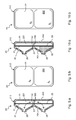
- Figure 9.a shows a cross-section view of the transducer protector during its normal operation.
- the inner duct 221 contains air only, in order to provide the pressure of the branch pipe 27 to the transducer 28. Air can flow along the inner duct 221: it enters the tubular connector 25, passes through the first membrane 23, through the passageway 320, through the second membrane 24 and exits the tubular connector 26.
- Air can also flow backwards along the inner duct 221.
- Figure 9.b shows a front view of the same transducer protector during its normal operation, i.e. figure 9.b shows what the service personnel can see while looking at the transducer protector.
- the transducer protector during its normal operation, is completely clear.
- Figure 10.a shows a cross-section view of the transducer protector 20 after the patient's blood 30, due to pressure fluctuations, has entered the branch pipe 27 and the first tubular connector 25.
- the first membrane 23 has duly stopped the blood flow so as to prevent contamination of the pressure transducer 28.
- the portion of the inner duct 221 comprised between the first tubular connector 25 and the first membrane 23 has evidently a different colour with respect to the same portion of figure 9.a .
- the light grey colour of the attached black-and-white figures 10.a , 11-12 and 15 would be actually bright red in facts.
- the front view of the transducer protector 20, in such conditions would probably show a slight change in the colour of the first membrane 23. However such slight change is not considered to be sufficiently evident in order to be a reliable warning signal for the service personnel.
- figure 10.b shows a completely clear transducer protector 20 like figure 9.b .
- Figure 11.a shows a cross-section view of the transducer protector 20 after the patient's blood 30 has passed through the first membrane 23.
- the portion of the inner duct 221 comprised between the first membrane 23 and the second membrane 24 has partially changed colour with respect to the previous figures 9.a and 10.a .
- the front view of the transducer protector 20 shows an evident change in its colour, turning to a bright red in facts (light grey in the figures). Such change is sufficiently evident to be an actual warning signal for the service personnel.
- Figure 12.a shows a cross-section view of the transducer protector 20 after the patient's blood 30 has completely filled the whole portion of the inner duct 221 comprised between the first membrane 23 and the second membrane 24.
- the second membrane 24 has duly stopped the blood flow so as to prevent contamination of the transducer.
- the front view of the transducer protector 20 ( figure 12.b ) shows an evident and total change in its colour, turning to a bright red in facts (light grey in the figures). Such change, due to the sharp contrast between the very light colour of the membranes and the bright red of blood, is very evident for the service personnel.
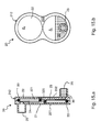
- Figures 15 show different operating configurations of a transducer protector 20 according to the embodiment of figures 13 and 14 .
- Figure 15.a shows a cross-section view of the transducer protector, similar to the one of figure 10.a .
- figure 15.a shows a cross-section view of the transducer protector 20 after the patient's blood 30, due to pressure fluctuations, has entered the branch pipe 27 and the first tubular connector 25.
- the first membrane 23 has duly stopped the blood flow so as to prevent contamination of the pressure transducer 28.
- in figures 15 also the front view of the transducer protector 20 ( figure 15.b ), shows an evident change in the colour of the first membrane 23.
- the presence of two membranes in series is effective in reducing the risk of contamination on a merely statistical basis.
- the specific arrangement of the transducer protectors 20 according to the invention not only provides two membranes in series, but also permits the service personnel to opportunely detect a failure and to intervene at the right time.
- the blood 30 takes a lot of time to completely fill the portion of the inner duct 221 comprised between the first membrane 23 and the second membrane 24 so as to reach the configuration of figures 12 . During such period of time the service personnel can easily detect the failure and intervene in order to solve the problem.
- the transducer protector 20 has a preferable (or "right") vertical orientation for its connection to the circuit 19.
- the patient's blood 30 gathers, due to gravity, in a specific portion of the duct 221. It is thus possible to define a lower portion (collecting blood 30) and an opposite upper portion.
- the first tubular connector 25 is placed under the second tubular connector 26.
- the blood 30 would take a shorter period of time to completely fill the portion of the duct 221 comprised between the two membranes 23 and 24. Accordingly, the wrong orientation of the transducer protector 20 provides a reduced safety margin for detecting and solving a problem.
- the first tubular connector 25 is specifically designed to be connected to the branch pipe 27, while the second tubular connector 26 is specifically designed to be connected to the transducer 28. According to such embodiments, due to the differences between the first and the second tubular connectors, the right orientation can be defined for the transducer protector 20 taken alone.
- the first and second tubular connectors are indistinguishable one from the other.
- the right orientation can be defined for the transducer protector 20 only with respect to the circuit 19 and the connections thereto.
- the transducer protector 20 permits to overcome almost completely the drawbacks pointed out with respect to the prior art.
- the front 202 of the transducer protector 20 is intended to be widely visible all along the operation.
- the translucent portion of the latter openly changes colour, typically from white to bright red.
- transducer protector 20 during normal operation of the transducer protector 20, service personnel can reasonably see the transducer protector 20 only from a front or, at most, a side point of view, see figures 18 and 19 . In fact the transducer protector 20 is connected on its back to the panel of the transducer 28 which completely prevents the rear view. As a consequence, according to the invention, a leakage of the first membrane implies an evident change in the colour of the front 202 of the transducer protector 20.
- front visibility is much more relevant than back visibility
- the front 202 is completely free from hindrance for the service personnel's sight.
Landscapes
- Health & Medical Sciences (AREA)
- Heart & Thoracic Surgery (AREA)
- Vascular Medicine (AREA)
- Life Sciences & Earth Sciences (AREA)
- Engineering & Computer Science (AREA)
- Anesthesiology (AREA)
- Biomedical Technology (AREA)
- Hematology (AREA)
- Cardiology (AREA)
- Animal Behavior & Ethology (AREA)
- General Health & Medical Sciences (AREA)
- Public Health (AREA)
- Veterinary Medicine (AREA)
- Physics & Mathematics (AREA)
- General Physics & Mathematics (AREA)
- External Artificial Organs (AREA)
Abstract
The present invention relates to a safety insert 20 for an extra-corporeal circuit 19. The safety insert, comprises: a first half-shell 21 and a second half-shell 22 forming a shell 212 defining an inner duct 221, at least part of the second half-shell being made with a translucent or transparent material; a first tubular connector 25 adapted to be connected to a branch pipe 27 from the extra-corporeal circuit, and a second tubular connector 26 defined by the first half-shell and adapted to be connected to a transducer 28; and a first hydrophobic semi-permeable membrane 23 having a first membrane area A1 and a second hydrophobic semi-permeable membrane 24 having a second membrane area A2, said two membranes being arranged in series along said inner duct 221. In a front view, the extent of an overlapping area A12 of said membranes is comprised between 0% and 50% of the smaller of said two membrane areas A1, A2.
The inventions further relates to an extra-corporeal circuit 19 comprising the above safety insert.
Description
- The invention relates to a safety insert for extra-corporeal circuits, in particular a transducer protector for preventing contamination of a pressure gauge on the extra-corporeal circuit.
- In therapeutic treatments which require an extra-corporeal circulation system, such as haemodialysis, the arterial and venous pressure in the extra-corporeal circuit must be constantly monitored. This is achieved in a manner known per se by means of pressure transducers connected to the main circuit via suitable branch pipes. In an equally known manner, a safety insert or transducer protector is positioned between the pipe and the pressure transducer in order to avoid any possible contact between the patient's blood and the machine (artificial kidney). In fact, the extra-corporeal circuit is made of disposable material, while the artificial kidney as a whole must, of necessity, be continuously reused.
- The transducer protector is formed, in a manner known per se, by means of a plastic shell enclosing a hydrophobic gas permeable membrane. Each side of the shell comprises a tubular connector. A first tubular connector is designed to be connected to the branch pipe, while the other tubular connector is designed to be connected to the pressure transducer.
- Due to pressure fluctuations, the patient's blood can enter the branch pipe and the first tubular connector. In such a case, the membrane is intended to stop the blood flow so as to prevent contamination of the machine. In a minor number of cases, the membrane can leak or even break and a contamination of the machine can occur without any notice of the service personnel.
- In order to increase the overall safety margin of the system, also such a rare incident should be avoided. Double transducer protectors have been provided for this reason.
- According to its first version, the double transducer protector simply comprises two membranes in series. Such device is very simple, but its effectiveness in reducing the risk of contamination relies on a merely statistical basis. A transducer protector of this type is disclosed in
EP 1 605 990 . - Other versions of double transducer protectors have two membranes in series and means to detect the presence of a contaminant between the membranes. Such devices are adapted to alert the service personnel in case of leakage of the first membrane, thus actually increasing the overall safety margin. In turn, such devices are quite complex and require additional components for the system. Transducer protectors of this type are disclosed in
EP 1 547 630 and inEP 1 728 526 . - The object of the present invention is therefore to solve at least partially the drawbacks identified in connection with the transducer protectors of the known types.
- An aim of the present invention is to provide a transducer protector for extra-corporeal circuits which provides a greater intrinsic safety margin.
- In particular, an aim of the present invention is to provide a transducer protector with a very simple and inexpensive structure.
- Furthermore, an aim of the present invention is to provide a transducer protector which permits to the service personnel to opportunely detect a failure and to intervene at the right time.
- The abovementioned object and aims are achieved by a transducer protector according to Claim 1.
- The characteristic features and further advantages of the invention will emerge more clearly from the following description provided below, of a number of examples of embodiment, described by way of a non-limiting example, with reference to the accompanying drawings in which:
-
Figure 1 shows in schematic form an extra-corporeal circuit used in therapeutic treatment according to the prior art; -
Figure 2 is a front view of the detail indicated with II in the extra-corporeal circuit offigure 1 ; -
Figure 3 is a side view of the detail offigure 2 ; -
Figure 4 shows a front view of a transducer protector according to the invention; -
Figure 5 shows a side view of the transducer protector offigure 4 ; -
Figure 6 shows a rear view of the transducer protector offigure 4 ; -
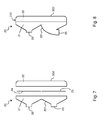
Figure 7 shows a side exploded view of the transducer protector offigure 4 ; -
Figure 8 shows a side view of another transducer protector according to the invention; -
Figure 9.a shows a side cross-section view of the transducer protector offigure 4 , - in a first operating configuration;
-
Figure 9.b shows a front view of the transducer protector offigure 9.a ; -
Figure 10.a shows a side cross-section view of the transducer protector offigure 4 , in a second operating configuration; -
Figure 10.b shows a front view of the transducer protector offigure 10.a ; -
Figure 11.a shows a side cross-section view of the transducer protector offigure 4 , in a third operating configuration; -
Figure 11.b shows a front view of the transducer protector offigure 11.a ; -
Figure 12.a shows a side cross-section view of the transducer protector offigure 4 , in a fourth operating configuration; -
Figure 12.b shows a front view of the transducer protector offigure 12.a ; -
Figure 13 shows a side view of a further transducer protector according to the invention; -
Figure 14 shows a front view of the transducer protector offigure 13 ; -
Figure 15.a shows a side cross-section view of the transducer protector offigure 13 , in an operating configuration similar to that offigure 10.a ; -
Figure 15.b shows a front view of the transducer protector offigure 15.a ; -
Figure 16 shows a front view of a transducer protector according to the invention; -
Figure 17 shows a front view of a transducer protector according to the invention; -
Figure 18.a is a front view of a detail similar to that offigure 2 , in an extra-corporeal circuit comprising the transducer protector offigure 4 ; -
Figure 18.b is a side view of the detail offigure 18.a ; -
Figure 19.a is a front view of a detail similar to that offigure 2 , in an extra-corporeal circuit comprising the transducer protector offigure 14 ; -
Figure 19.b is a side view of the detail offigure 19.a . - The present invention relates to a
safety insert 20 for anextra-corporeal circuit 19. The safety insert 20, or transducer protector, comprises: - a first half-
shell 21 and a second half-shell 22 forming ashell 212 defining aninner duct 221, at least part of the second half-shell 22 being made with a translucent or transparent material; - a first
tubular connector 25 adapted to be connected to abranch pipe 27 from theextra-corporeal circuit 19, and a secondtubular connector 26 defined by the first half-shell 21 and adapted to be connected to atransducer 28; and - a first hydrophobic
semi-permeable membrane 23 having a first membrane area A1 and a second hydrophobicsemi-permeable membrane 24 having a second membrane area A2, said twomembranes inner duct 221. - In the safety insert 20 according to the invention, in a front view, the extent of an overlapping area A12 of said
membranes - In the enclosed
figures 18 and 19 , thetransducer protector 20 is shown properly arranged in its operation configuration, i.e. connected both to thebranch pipe 27 and to thetransducer 28. With reference also to such figures, the operation configuration of thetransducer protector 20 defines aback 201 and afront 202. Here and below, the terms "back", "backward", "rear" and the like, refer to positions in thetransducer protector 20 relatively close, in use, to the panel of thetransducer 28. On the other hand, the terms "front", "forward", "ahead" and the like, refer to positions relatively distant from the panel of thetransducer 28. According to the invention, at least part of the second half-shell 22 is made with a translucent or transparent material, e.g. polycarbonate or other medical grade materials. According to different embodiments of the invention, the translucent portion may be provided at different extents. For example, the whole second half-shell 22 may be made with a translucent or transparent material. Preferably, thewhole shell 212 is translucent, i.e. both the first half-shell 21 and the second half-shell 22 are made with a translucent material. - As already pointed out, in a front view, the extent of the overlapping area A12 of said
membranes membranes first membrane 23 passes also through thesecond membrane 24, or vice versa. Of course such definition directly implies a definition of the overlapping area A12. However, notwithstanding the definition, the skilled person will easily understand the meaning of such wording, especially in view of the following. - According to many embodiments, the extent of the overlapping area A12 is equal to 0, i.e. the
membranes Figures 4 to 15 ,18 and 19 show such kind of embodiments. On the contrary,figures 16 and 17 show front views of two different embodiments of the invention wherein the extent of the overlapping area A12 is greater than zero, i.e. themembranes - According to many embodiments of the invention, each of said first and
second membrane membranes membranes - According to an embodiment of the invention, the colour of the
membranes - According to some embodiments of the invention (see for example
figures 4 to 12 ,16 and18 ), both the first and the secondtubular connectors shell 21. In other words, both thetubular connectors transducer protector 20. Accordingly, in such embodiments, thefront 202 of thetransducer protector 20 is completely plain. In other words, the front 202 is free from any element which could prevent or even reduce its visibility. - According to such embodiments (see for example
fig. 9.a ), theduct 221 starts on the back 201 at the firsttubular connector 25, it goes forward through thefirst membrane 23, then it goes back through thesecond membrane 24 and it ends again on the back 201, at the secondtubular connector 26. - According to the embodiments of
figures 4 to 12 ,16 and18 , saidfirst membrane 23 and saidsecond membrane 24 can be obtained either by means of two separate pieces of a suitable film, or by means of a single piece. In any case, the two membranes have to be firmly separated one from the other on their back. In this manner, theduct 221 goes forward through thefirst membrane 23 and then goes back through thesecond membrane 24 rather than passing on the back of the two membranes. According to the embodiment shown in the attached figures, such firm separation is obtained by means of tworibs shell 21 and the second half-shell 22 respectively. Thesecond rib 32 of the second half-shell 22 defines apassageway 320 intended to guarantee the continuity of theduct 221. - According to some other embodiments of the invention (see for example
figures 13-15 ,17 and19 ), while the secondtubular connector 26 is defined by the first half-shell 21, the firsttubular connector 25 is defined by the second half-shell 22. In other words, the secondtubular connector 26 is placed on the back 201 of thetransducer protector 20, while the firsttubular connector 25 is placed on itsfront 202. - According to such embodiments (see
figure 15.a ), theduct 221 starts on the front 202 at the firsttubular connector 25, it goes backward through thefirst membrane 23, then it goes forward along thepassageway 320, it goes backward again through thesecond membrane 24 and it ends on the back 201, at the secondtubular connector 26. - According to the embodiments of
figures 13-15 ,17 and19 , saidfirst membrane 23 and saidsecond membrane 24 are preferably obtained by means of two separate pieces, in order to let thepassageway 320 pass between them, but they can be one single piece since thepassageway 320 can be lateral. According to the embodiment shown in the attached figures, themembranes rings 33, otherwise they can be directly welded to the body of thehalf shells shells passageway 320 intended to guarantee the continuity of theduct 221. -
Figures 9 to 12 show different operating configurations of atransducer protector 20 according to the embodiment offigures 4-7 and18 .Figure 9.a shows a cross-section view of the transducer protector during its normal operation. In such conditions theinner duct 221 contains air only, in order to provide the pressure of thebranch pipe 27 to thetransducer 28. Air can flow along the inner duct 221: it enters thetubular connector 25, passes through thefirst membrane 23, through thepassageway 320, through thesecond membrane 24 and exits thetubular connector 26. Of course, according to the pressure variation, air can also flow backwards along theinner duct 221. These flows are schematically indicated by means of the double dotted arrows infigure 9.a. Figure 9.b shows a front view of the same transducer protector during its normal operation, i.e.figure 9.b shows what the service personnel can see while looking at the transducer protector. As can be appreciated, the transducer protector, during its normal operation, is completely clear. -
Figure 10.a shows a cross-section view of thetransducer protector 20 after the patient'sblood 30, due to pressure fluctuations, has entered thebranch pipe 27 and the firsttubular connector 25. Thefirst membrane 23 has duly stopped the blood flow so as to prevent contamination of thepressure transducer 28. Infigure 10.a , the portion of theinner duct 221 comprised between the firsttubular connector 25 and thefirst membrane 23 has evidently a different colour with respect to the same portion offigure 9.a . It should be noted here that the light grey colour of the attached black-and-whitefigures 10.a ,11-12 and15 would be actually bright red in facts. Also the front view of thetransducer protector 20, in such conditions, would probably show a slight change in the colour of thefirst membrane 23. However such slight change is not considered to be sufficiently evident in order to be a reliable warning signal for the service personnel. Accordingly,figure 10.b shows a completelyclear transducer protector 20 likefigure 9.b . - In a minor number of cases, the
first membrane 23 can leak or even break so as to let the blood flow through it.Figure 11.a shows a cross-section view of thetransducer protector 20 after the patient'sblood 30 has passed through thefirst membrane 23. Infigure 11.a , the portion of theinner duct 221 comprised between thefirst membrane 23 and thesecond membrane 24 has partially changed colour with respect to the previousfigures 9.a and 10.a . In such conditions, also the front view of the transducer protector 20 (figure 11.b ) shows an evident change in its colour, turning to a bright red in facts (light grey in the figures). Such change is sufficiently evident to be an actual warning signal for the service personnel. -
Figure 12.a shows a cross-section view of thetransducer protector 20 after the patient'sblood 30 has completely filled the whole portion of theinner duct 221 comprised between thefirst membrane 23 and thesecond membrane 24. Thesecond membrane 24 has duly stopped the blood flow so as to prevent contamination of the transducer. In such conditions, the front view of the transducer protector 20 (figure 12.b ) shows an evident and total change in its colour, turning to a bright red in facts (light grey in the figures). Such change, due to the sharp contrast between the very light colour of the membranes and the bright red of blood, is very evident for the service personnel. -
Figures 15 show different operating configurations of atransducer protector 20 according to the embodiment offigures 13 and 14 .Figure 15.a shows a cross-section view of the transducer protector, similar to the one offigure 10.a . In particular,figure 15.a shows a cross-section view of thetransducer protector 20 after the patient'sblood 30, due to pressure fluctuations, has entered thebranch pipe 27 and the firsttubular connector 25. Thefirst membrane 23 has duly stopped the blood flow so as to prevent contamination of thepressure transducer 28. In a different manner with respect to the same condition described with respect tofigures 10 , infigures 15 also the front view of the transducer protector 20 (figure 15.b ), shows an evident change in the colour of thefirst membrane 23. - Such change is sufficiently evident to be an actual warning signal for the service personnel. In other words, according to the embodiment of
figures 13-15 , a warning signal is available for the service personnel immediately after the patient'sblood 30 has entered the firsttubular connector 25. As can be easily appreciated by the skilled person, the earlier the warning signal, the larger the safety margin to avoid any problem. - Of course, as already pointed out with respect to the prior art double transducer protectors, the presence of two membranes in series is effective in reducing the risk of contamination on a merely statistical basis. However, it should be noted that the specific arrangement of the
transducer protectors 20 according to the invention, not only provides two membranes in series, but also permits the service personnel to opportunely detect a failure and to intervene at the right time. In fact, theblood 30 takes a lot of time to completely fill the portion of theinner duct 221 comprised between thefirst membrane 23 and thesecond membrane 24 so as to reach the configuration offigures 12 . During such period of time the service personnel can easily detect the failure and intervene in order to solve the problem. It should be noted here that, with reference tofigures 11 , thetransducer protector 20 has a preferable (or "right") vertical orientation for its connection to thecircuit 19. As can be appreciated infigures 11 and15 , the patient'sblood 30 gathers, due to gravity, in a specific portion of theduct 221. It is thus possible to define a lower portion (collecting blood 30) and an opposite upper portion. - In view of the above, in the right orientation of the
transducer protector 20, the firsttubular connector 25 is placed under the secondtubular connector 26. According to an opposite (or "wrong") orientation of thetransducer protector 20, wherein the firsttubular connector 25 is placed over the secondtubular connector 26, theblood 30 would take a shorter period of time to completely fill the portion of theduct 221 comprised between the twomembranes transducer protector 20 provides a reduced safety margin for detecting and solving a problem. - In some embodiments of the invention, the first
tubular connector 25 is specifically designed to be connected to thebranch pipe 27, while the secondtubular connector 26 is specifically designed to be connected to thetransducer 28. According to such embodiments, due to the differences between the first and the second tubular connectors, the right orientation can be defined for thetransducer protector 20 taken alone. - On the contrary, according to some other embodiments of the invention, the first and second tubular connectors are indistinguishable one from the other. According to such embodiments, the right orientation can be defined for the
transducer protector 20 only with respect to thecircuit 19 and the connections thereto. - As the skilled person may easily appreciate, the
transducer protector 20 according to the invention permits to overcome almost completely the drawbacks pointed out with respect to the prior art. In fact, thefront 202 of thetransducer protector 20 is intended to be widely visible all along the operation. In particular, if the patient'sblood 30 passes thefirst membrane 23 due to a leakage and enters the second half-shell 22, the translucent portion of the latter openly changes colour, typically from white to bright red. The possibility to easily see the second half-shell 22, because of the tubular connectors being on the back, and its change of colour, because of the presence ofblood 30 therein, enable the service personnel to opportunely detect the failure and to intervene at the right time. - It should be noted here that during normal operation of the
transducer protector 20, service personnel can reasonably see thetransducer protector 20 only from a front or, at most, a side point of view, seefigures 18 and 19 . In fact thetransducer protector 20 is connected on its back to the panel of thetransducer 28 which completely prevents the rear view. As a consequence, according to the invention, a leakage of the first membrane implies an evident change in the colour of thefront 202 of thetransducer protector 20. - Moreover, since front visibility is much more relevant than back visibility, according to some embodiments, the front 202 is completely free from hindrance for the service personnel's sight.
- With regard to the embodiments of the transducer protector described above, the person skilled in the art may, in order to satisfy specific requirements, make modifications to and/or replace elements described with equivalent elements, without thereby departing from the scope of the accompanying claims.
Claims (12)
- Safety insert (20) or transducer protector for an extra-corporeal circuit (19), comprising:a first half-shell (21) and a second half-shell (22) forming a shell (212) defining an inner duct (221), at least part of the second half-shell (22) being made with a translucent or transparent material;a first tubular connector (25) adapted to be connected to a branch pipe (27) from the extra-corporeal circuit (19), and a second tubular connector (26) defined by the first half-shell (21) and adapted to be connected to a transducer (28); anda first hydrophobic semi-permeable membrane (23) having a first membrane area (A1) and a second hydrophobic semi-permeable membrane (24) having a second membrane area (A2), said two membranes (23, 24) being arranged in series along said inner duct (221);wherein, in a front view, an overlapping area (A12) of said membranes (23, 24) is comprised between 0% and 50% of the smaller between said two membrane areas (A1, A2).
- Insert (20) according to Claim 1, wherein its operation configuration defines a back (201) of the insert (20), facing the transducer (28), and a front (202) of the insert (20).
- Insert (20) according to Claim 1 or 2, wherein the first tubular connector (25) is defined by the first half-shell (21).
- Insert (20) according to Claim 3, wherein its front (202) is completely plain and free from any element which could prevent or reduce its visibility.
- Insert (20) according to Claim 1 or 2, wherein the first tubular connector (25) is defined by the second half-shell (22).
- Insert (20) according to any one of the preceding claims, wherein the whole second half-shell (22) is made with a translucent or transparent material.
- Insert (20) according to any one of the preceding claims, wherein the first and second membranes (23, 24) are white.
- Insert (20) according to any one of the preceding claims, wherein said first and second membranes (23, 24) are arranged in a planar configuration.
- Insert (20) according to any one of the preceding claims, wherein said first and second membranes (23, 24) lie on parallel planes.
- Insert (20) according to any one of the preceding claims, wherein said first and second membranes (23, 24) lie on the same plane.
- Extra-corporeal circuit (19) comprising at least one safety insert (20) according to any one of the preceding claims.
- Circuit (19) according to claim 8 further comprising a pressure transducer (28) and a branch pipe (27), wherein the first tubular connector (25) connected to the branch pipe (27) is placed under the second tubular connector (26) connected to the transducer (28).
Priority Applications (4)
| Application Number | Priority Date | Filing Date | Title |
|---|---|---|---|
| EP09160691A EP2253343A1 (en) | 2009-05-19 | 2009-05-19 | Safety insert for extra-corporeal circuits |
| US13/321,023 US9067025B2 (en) | 2009-05-19 | 2010-05-14 | Safety insert for extra-corporeal circuits |
| EP10722988.2A EP2432520B1 (en) | 2009-05-19 | 2010-05-14 | Safety insert for extra-corporeal circuits |
| PCT/EP2010/056640 WO2010133515A1 (en) | 2009-05-19 | 2010-05-14 | Safety insert for extra-corporeal circuits |
Applications Claiming Priority (1)
| Application Number | Priority Date | Filing Date | Title |
|---|---|---|---|
| EP09160691A EP2253343A1 (en) | 2009-05-19 | 2009-05-19 | Safety insert for extra-corporeal circuits |
Publications (1)
| Publication Number | Publication Date |
|---|---|
| EP2253343A1 true EP2253343A1 (en) | 2010-11-24 |
Family
ID=41266781
Family Applications (2)
| Application Number | Title | Priority Date | Filing Date |
|---|---|---|---|
| EP09160691A Withdrawn EP2253343A1 (en) | 2009-05-19 | 2009-05-19 | Safety insert for extra-corporeal circuits |
| EP10722988.2A Active EP2432520B1 (en) | 2009-05-19 | 2010-05-14 | Safety insert for extra-corporeal circuits |
Family Applications After (1)
| Application Number | Title | Priority Date | Filing Date |
|---|---|---|---|
| EP10722988.2A Active EP2432520B1 (en) | 2009-05-19 | 2010-05-14 | Safety insert for extra-corporeal circuits |
Country Status (3)
| Country | Link |
|---|---|
| US (1) | US9067025B2 (en) |
| EP (2) | EP2253343A1 (en) |
| WO (1) | WO2010133515A1 (en) |
Cited By (1)
| Publication number | Priority date | Publication date | Assignee | Title |
|---|---|---|---|---|
| DE102012018078A1 (en) | 2012-09-13 | 2014-03-13 | Fresenius Medical Care Deutschland Gmbh | Pressure transducer protection device for blood tube systems |
Families Citing this family (1)
| Publication number | Priority date | Publication date | Assignee | Title |
|---|---|---|---|---|
| US20100266638A1 (en) | 2004-02-26 | 2010-10-21 | Allergan, Inc. | Headache treatment method |
Citations (3)
| Publication number | Priority date | Publication date | Assignee | Title |
|---|---|---|---|---|
| EP1547630A1 (en) | 2003-12-23 | 2005-06-29 | Ludwig Teugels | Double membrane transducer protector |
| EP1605990A2 (en) | 2003-03-21 | 2005-12-21 | Gambro Lundia AB | A device for protecting medical apparatus. |
| EP1728526A1 (en) | 2005-06-03 | 2006-12-06 | Fresenius Medical Care Deutschland GmbH | System for monitoring the pressure in a blood line and a device to be used with such a system |
Family Cites Families (1)
| Publication number | Priority date | Publication date | Assignee | Title |
|---|---|---|---|---|
| EP2229966A1 (en) * | 2009-03-18 | 2010-09-22 | Fresenius Medical Care Deutschland GmbH | Safety insert for extra-corporeal circuits |
-
2009
- 2009-05-19 EP EP09160691A patent/EP2253343A1/en not_active Withdrawn
-
2010
- 2010-05-14 EP EP10722988.2A patent/EP2432520B1/en active Active
- 2010-05-14 WO PCT/EP2010/056640 patent/WO2010133515A1/en not_active Ceased
- 2010-05-14 US US13/321,023 patent/US9067025B2/en active Active
Patent Citations (3)
| Publication number | Priority date | Publication date | Assignee | Title |
|---|---|---|---|---|
| EP1605990A2 (en) | 2003-03-21 | 2005-12-21 | Gambro Lundia AB | A device for protecting medical apparatus. |
| EP1547630A1 (en) | 2003-12-23 | 2005-06-29 | Ludwig Teugels | Double membrane transducer protector |
| EP1728526A1 (en) | 2005-06-03 | 2006-12-06 | Fresenius Medical Care Deutschland GmbH | System for monitoring the pressure in a blood line and a device to be used with such a system |
Cited By (2)
| Publication number | Priority date | Publication date | Assignee | Title |
|---|---|---|---|---|
| DE102012018078A1 (en) | 2012-09-13 | 2014-03-13 | Fresenius Medical Care Deutschland Gmbh | Pressure transducer protection device for blood tube systems |
| WO2014040743A1 (en) * | 2012-09-13 | 2014-03-20 | Fresenius Medical Care Deutschland Gmbh | Pressure transducer protection device for blood line systems |
Also Published As
| Publication number | Publication date |
|---|---|
| US9067025B2 (en) | 2015-06-30 |
| EP2432520A1 (en) | 2012-03-28 |
| US20120114886A1 (en) | 2012-05-10 |
| EP2432520B1 (en) | 2016-11-09 |
| WO2010133515A1 (en) | 2010-11-25 |
Similar Documents
| Publication | Publication Date | Title |
|---|---|---|
| EP2408490B1 (en) | Safety insert for extra-corporeal circuits | |
| EP3305344B1 (en) | Medical liquid pressure detection device | |
| EP1728526B1 (en) | System for monitoring the pressure in a blood line and a device to be used with such a system | |
| JP4118233B2 (en) | Method and apparatus for detecting fluid line leaks | |
| US20080183120A1 (en) | Blood leak monitoring method and apparatus | |
| ES2262273T3 (en) | PROCEDURE AND DEVICE FOR CHECKING THE CORRECT REPLACEMENT OF A FILTER USED IN A DEVICE FOR THE STRATORPORAL TREATMENT OF BLOOD. | |
| US10940253B2 (en) | Blood purification apparatus | |
| EP3248629A1 (en) | Blood purification device | |
| US9629993B2 (en) | Tubing adapter for influencing the pressure inside a tubing section during a medical treatment | |
| US10940252B2 (en) | Blood purification apparatus | |
| CN106687156B (en) | blood purification device | |
| CN102114279A (en) | Infusion pump | |
| EP2432520B1 (en) | Safety insert for extra-corporeal circuits | |
| US10254916B2 (en) | Systems and methods for monitoring and correcting defects and tubing installation errors for blood processing systems | |
| CN109414541B (en) | Control unit for detecting blood in a dialysate discharge line of a blood treatment device and blood treatment device | |
| US9561319B2 (en) | Device and method for fixing a segment of tubing, for an arrangement for monitoring an access to a patient | |
| EP1260238A2 (en) | Blood collection device | |
| US20070208292A1 (en) | Device For Exchanging And/Or Docking Functional Modules | |
| CN209951903U (en) | Extracorporeal circulation pipeline for blood purification device | |
| JP2025176759A (en) | extracorporeal circulation circuit | |
| US10426881B2 (en) | Enhanced backflow prevention in a hemodialysis device | |
| CN103463699A (en) | Pressure-guided infusion alarm device |
Legal Events
| Date | Code | Title | Description |
|---|---|---|---|
| PUAI | Public reference made under article 153(3) epc to a published international application that has entered the european phase |
Free format text: ORIGINAL CODE: 0009012 |
|
| AK | Designated contracting states |
Kind code of ref document: A1 Designated state(s): AT BE BG CH CY CZ DE DK EE ES FI FR GB GR HR HU IE IS IT LI LT LU LV MC MK MT NL NO PL PT RO SE SI SK TR |
|
| AX | Request for extension of the european patent |
Extension state: AL BA RS |
|
| STAA | Information on the status of an ep patent application or granted ep patent |
Free format text: STATUS: THE APPLICATION IS DEEMED TO BE WITHDRAWN |
|
| 18D | Application deemed to be withdrawn |
Effective date: 20110525 |