EP2252745B1 - Insulation holder and method - Google Patents
Insulation holder and method Download PDFInfo
- Publication number
- EP2252745B1 EP2252745B1 EP09707658.2A EP09707658A EP2252745B1 EP 2252745 B1 EP2252745 B1 EP 2252745B1 EP 09707658 A EP09707658 A EP 09707658A EP 2252745 B1 EP2252745 B1 EP 2252745B1
- Authority
- EP
- European Patent Office
- Prior art keywords
- insulation
- side wall
- supporting
- flange
- support
- Prior art date
- Legal status (The legal status is an assumption and is not a legal conclusion. Google has not performed a legal analysis and makes no representation as to the accuracy of the status listed.)
- Active
Links
- 238000009413 insulation Methods 0.000 title claims description 61
- 238000000034 method Methods 0.000 title claims description 11
- 239000000463 material Substances 0.000 claims description 28
- 239000004033 plastic Substances 0.000 claims description 16
- 239000002344 surface layer Substances 0.000 claims description 13
- 239000011810 insulating material Substances 0.000 claims description 7
- 238000003860 storage Methods 0.000 claims description 7
- 239000010410 layer Substances 0.000 description 11
- 239000012774 insulation material Substances 0.000 description 10
- 238000009408 flooring Methods 0.000 description 4
- 230000000295 complement effect Effects 0.000 description 3
- 238000005520 cutting process Methods 0.000 description 3
- 238000004519 manufacturing process Methods 0.000 description 3
- XLYOFNOQVPJJNP-UHFFFAOYSA-N water Substances O XLYOFNOQVPJJNP-UHFFFAOYSA-N 0.000 description 3
- 229930186657 Lat Natural products 0.000 description 2
- 239000006260 foam Substances 0.000 description 2
- 239000002985 plastic film Substances 0.000 description 2
- 239000007787 solid Substances 0.000 description 2
- 238000005728 strengthening Methods 0.000 description 2
- 230000003313 weakening effect Effects 0.000 description 2
- 239000004743 Polypropylene Substances 0.000 description 1
- 239000004793 Polystyrene Substances 0.000 description 1
- 239000002390 adhesive tape Substances 0.000 description 1
- 230000009286 beneficial effect Effects 0.000 description 1
- 238000005253 cladding Methods 0.000 description 1
- 230000008602 contraction Effects 0.000 description 1
- 238000007796 conventional method Methods 0.000 description 1
- 239000011152 fibreglass Substances 0.000 description 1
- 238000010438 heat treatment Methods 0.000 description 1
- 238000012423 maintenance Methods 0.000 description 1
- 238000012856 packing Methods 0.000 description 1
- -1 polypropylene Polymers 0.000 description 1
- 229920001155 polypropylene Polymers 0.000 description 1
- 229920002223 polystyrene Polymers 0.000 description 1
- 239000002356 single layer Substances 0.000 description 1
- 125000006850 spacer group Chemical group 0.000 description 1
Images




Classifications
-
- E—FIXED CONSTRUCTIONS
- E04—BUILDING
- E04B—GENERAL BUILDING CONSTRUCTIONS; WALLS, e.g. PARTITIONS; ROOFS; FLOORS; CEILINGS; INSULATION OR OTHER PROTECTION OF BUILDINGS
- E04B1/00—Constructions in general; Structures which are not restricted either to walls, e.g. partitions, or floors or ceilings or roofs
- E04B1/62—Insulation or other protection; Elements or use of specified material therefor
- E04B1/74—Heat, sound or noise insulation, absorption, or reflection; Other building methods affording favourable thermal or acoustical conditions, e.g. accumulating of heat within walls
- E04B1/76—Heat, sound or noise insulation, absorption, or reflection; Other building methods affording favourable thermal or acoustical conditions, e.g. accumulating of heat within walls specifically with respect to heat only
- E04B1/7654—Heat, sound or noise insulation, absorption, or reflection; Other building methods affording favourable thermal or acoustical conditions, e.g. accumulating of heat within walls specifically with respect to heat only comprising an insulating layer, disposed between two longitudinal supporting elements, e.g. to insulate ceilings
- E04B1/7658—Heat, sound or noise insulation, absorption, or reflection; Other building methods affording favourable thermal or acoustical conditions, e.g. accumulating of heat within walls specifically with respect to heat only comprising an insulating layer, disposed between two longitudinal supporting elements, e.g. to insulate ceilings comprising fiber insulation, e.g. as panels or loose filled fibres
- E04B1/7662—Heat, sound or noise insulation, absorption, or reflection; Other building methods affording favourable thermal or acoustical conditions, e.g. accumulating of heat within walls specifically with respect to heat only comprising an insulating layer, disposed between two longitudinal supporting elements, e.g. to insulate ceilings comprising fiber insulation, e.g. as panels or loose filled fibres comprising fiber blankets or batts
- E04B1/7666—Connection of blankets or batts to the longitudinal supporting elements
-
- E—FIXED CONSTRUCTIONS
- E04—BUILDING
- E04B—GENERAL BUILDING CONSTRUCTIONS; WALLS, e.g. PARTITIONS; ROOFS; FLOORS; CEILINGS; INSULATION OR OTHER PROTECTION OF BUILDINGS
- E04B1/00—Constructions in general; Structures which are not restricted either to walls, e.g. partitions, or floors or ceilings or roofs
- E04B1/62—Insulation or other protection; Elements or use of specified material therefor
- E04B1/74—Heat, sound or noise insulation, absorption, or reflection; Other building methods affording favourable thermal or acoustical conditions, e.g. accumulating of heat within walls
- E04B1/76—Heat, sound or noise insulation, absorption, or reflection; Other building methods affording favourable thermal or acoustical conditions, e.g. accumulating of heat within walls specifically with respect to heat only
- E04B1/7654—Heat, sound or noise insulation, absorption, or reflection; Other building methods affording favourable thermal or acoustical conditions, e.g. accumulating of heat within walls specifically with respect to heat only comprising an insulating layer, disposed between two longitudinal supporting elements, e.g. to insulate ceilings
-
- E—FIXED CONSTRUCTIONS
- E04—BUILDING
- E04D—ROOF COVERINGS; SKY-LIGHTS; GUTTERS; ROOF-WORKING TOOLS
- E04D13/00—Special arrangements or devices in connection with roof coverings; Protection against birds; Roof drainage ; Sky-lights
- E04D13/16—Insulating devices or arrangements in so far as the roof covering is concerned, e.g. characterised by the material or composition of the roof insulating material or its integration in the roof structure
- E04D13/1606—Insulation of the roof covering characterised by its integration in the roof structure
- E04D13/1612—Insulation of the roof covering characterised by its integration in the roof structure the roof structure comprising a supporting framework of roof purlins or rafters
- E04D13/1625—Insulation of the roof covering characterised by its integration in the roof structure the roof structure comprising a supporting framework of roof purlins or rafters with means for supporting the insulating material between the purlins or rafters
-
- Y—GENERAL TAGGING OF NEW TECHNOLOGICAL DEVELOPMENTS; GENERAL TAGGING OF CROSS-SECTIONAL TECHNOLOGIES SPANNING OVER SEVERAL SECTIONS OF THE IPC; TECHNICAL SUBJECTS COVERED BY FORMER USPC CROSS-REFERENCE ART COLLECTIONS [XRACs] AND DIGESTS
- Y10—TECHNICAL SUBJECTS COVERED BY FORMER USPC
- Y10T—TECHNICAL SUBJECTS COVERED BY FORMER US CLASSIFICATION
- Y10T29/00—Metal working
- Y10T29/49—Method of mechanical manufacture
- Y10T29/49995—Shaping one-piece blank by removing material
- Y10T29/49996—Successive distinct removal operations
Definitions
- the invention relates to an insulation apparatus, in particular an apparatus for supporting insulating materials in buildings.
- the invention also relates to an insulation system and a method of insulating a structure.
- Insulation is added to buildings to conserve energy by preventing heat loss through floors, walls, ceilings and lofts. As well as thermal insulation, buildings may be insulated to prevent noise.
- insulating materials include polystyrene, fibreglass, foam, plastic fibres or natural fibres. They may come in the form of blocks, boards, rolls, loose fill, foam, batts etc.
- the conventional way to lay insulation for example under a floor, is to lay nets across floor joists and pack insulation between the floor joists.
- the nets are required to hold the insulation in place and prevent it from falling through the space between joists.
- This method is time consuming as nets must first be laid and then sufficient insulation material must be tightly packed onto the net between the joists.
- a disadvantage of this method is that it often leads to ineffective insulation where the ends of the insulation material become compressed due to positioning on the nets.
- Another conventional method of laying insulation is to support the insulation on lats which are screwed to opposing surfaces on floor joists. Again, attaching the lats and packing the material onto them can be time consuming and this method is sometimes ineffective as it is possible for the insulation to fall between floor joists.
- a further disadvantage associated with both of the above methods is that pipes such as water or heating pipes often run at or below the level of insulation. Insulation may need to be removed to insert pipes after the building has been insulated. Also, access to pipes for maintenance or repair may be restricted or may require removal of a section of insulation and support.
- US 4,292,777 describes a cardboard structure for providing a space into which insulation material may be blown.
- the structure includes securing panels and spacer tabs, the securing panels being fastened to the sides of joists with staples.
- DE 297 22 192 U1 describes a structure including a folded base which supports insulation material and is attached to the underside of joists with staples or wedged between opposing side walls of adjacent joists.
- One aspect of the invention provides apparatus for supporting insulation as specified in Claim 1.
- Another aspect of the invention provides an insulation system as specified in Claim 11.
- Another aspect of the invention provides a method of insulating a structure as specified in Claim 13.
- Yet another aspect of the invention provides an insulated structure as specified in Claim 14.
- the invention provides an insulation support apparatus comprising an insulation holding portion and at least one supporting flange.
- the apparatus for supporting insulation comprises a base portion, at least one side wall and at least one supporting flange.
- the at least one side wall In an in use position the at least one side wall is substantially perpendicular to the base portion and in a storage position the at least one side wall and the at least one supporting flange are substantially parallel to the base portion.
- the apparatus is biased towards the in use position.
- At least one cut or score line facilitates biasing of the apparatus towards the in use position.
- the apparatus is formed substantially from a double skinned material.
- the double skinned material may comprise a first surface layer and a second surface layer with connecting elements between the layers.
- a portion of one surface layer is substantially weaker than a corresponding portion of the other surface layer.
- the apparatus comprises at least one cut or score line in the first surface layer and at least one cut or score line in the second surface layer.
- the cut or score line forms a pivot point about which the apparatus is pivotable.
- At least one supporting flange may be pivotable towards the at least one side wall.
- At least one side wall may be pivotable towards the base portion.
- the apparatus may also comprise insulating material.
- the supporting flange or flanges is/are arranged to engage a structural element of a building such as a joist or cladding.
- At least one portion of the apparatus is complementary to a portion of another apparatus.
- the apparatus may have an extending portion at one end, which may be arranged to engage a receiving portion of an adjacent apparatus when in use.
- each flange may include a region complementary to another flange such that the apparatus may co-operate with an adjacent support apparatus.
- Adjacent flanges may have overlapping and/or interlocking regions.
- the insulation holding portion comprises a base and at least one side wall extending from at least one flange.
- the insulation holding portion may be formed of plastic and/or mesh.
- the insulation holding portion may be in the form of a trough.
- the support apparatus includes strengthening elements such as ribs.
- the support may be formed of double skinned plastic.
- the plastic may be recycled plastic.
- the support and/or the insulation holding portion are substantially rigid.
- the side walls may be foldable towards the base of the insulation holding portion.
- the flanges may be foldable toward the base and/or the sidewalls.
- the support apparatus may comprise openings.
- the openings may be holes or open regions in a mesh.
- the openings may be arranged to accommodate pipes such as water pipes or cables.
- the support apparatus may comprise sound deadening elements, such as one or more layers of sound deadening materials.
- Another aspect of the invention provides an insulation system comprising more than one apparatus for supporting insulation.
- the insulation system is coded such that apparatus is readily identifiable.
- the system provides easy identification of each apparatus, with or without insulation, according to its properties.
- the insulation system is colour coded.
- Another aspect of the invention provides a method of insulating a structure such as a building, comprising the steps of a) engaging at least one supporting flange of an apparatus for supporting insulation with a structural element of a building and b) securing the apparatus to the structural element of a building.
- Yet another aspect of the invention provides an insulated structure comprising structural elements, at least one support apparatus and insulating material.
- An aspect of the invention may provide apparatus for supporting insulation comprising a base portion and at least one side wall, wherein in an in use position the at least one side wall is substantially perpendicular to the base portion and in a storage position the at least one side wall is parallel to the base portion and wherein the apparatus is formed substantially from double skinned material.
- a portion of one surface layer of the double skinned material is preferably substantially weaker than a corresponding portion of the other surface layer.
- Yet another aspect of the invention may provide a method of manufacture of apparatus for supporting insulation comprising the steps of:
- an insulation support 1 comprises flanges 2 and troughs 3.
- the flanges 2 may be stapled or nailed into position on joists 4 or studding in floors, walls and ceilings.
- Insulation material 5 is supported within the troughs 3.
- the apparatus comprises eight troughs. However, the number of troughs maybe varied. In an alternative embodiment the insulation support 1 may have a single trough 3.
- each trough 3 has ribs moulded into it for strength.
- the base of the troughs 3 may be solid or may include mesh or other openings to allow the insulation material to breathe.
- the mesh region may be a plastic type mesh arrangement or, for example, netting material.
- the walls of the troughs 3 may be solid or include openings as different types of insulation have different properties and requirements.
- the insulation support 1 may also include holes for electrical cables or water pipes.
- the insulation support 1 is preferably made of plastic. Different grades of plastic may be selected according to the particular intended application of the support. In a preferred embodiment, the insulation support 1 is made of double skinned plastic, with an air gap between inner and outer layers of plastic. A suitable material is fluted polypropylene.
- Insulation supports 1 may be coded for different sizes or applications, such that they are readily identifiable. For example, insulation supports may be colour coded so that those for use with floors are blue and those for use with walls are coloured brown.
- each support is around one metre in length.
- floor joists may be spaced at different distances in different buildings and insulation requirements may vary according to the area of type of insulation material, the width and depth of the supports 1 may be varied.
- insulation material 5 is packed into the troughs 3 after supports 1 have been secured in place on joists or wall studding. This means that insulation can be laid very quickly because there is no need to screw additional supports to the joists.
- the supports which are preferably around 1m long, can simply be laid between joists and stapled in place. In this way a large area can be covered very quickly.
- the support 1 and insulation 5 may be a ready-made unit that can be applied to floors, walls or ceilings in a single step. This means that insulation supports and insulation may be laid directly onto joists simultaneously.
- the insulation 5 is packed tightly against the walls of the troughs 3, which secures it in position.
- Figure 2a shows a side view of a number of supports 1a, 1b, 1c and 1d, holding insulation 5 between floor joists 4.
- Flooring 6 such as wooden flooring is laid over the floor joists 4.
- This arrangement is beneficial because if work needs to be carried out after insulation and/or flooring has been laid, the flooring and/or supports 1 in a particular region can be removed and replaced without affecting insulation under the rest of the floor. If pipes or cables need to be laid in a section of the insulation layer, the supports 1 can be removed and holes can be drilled in the necessary parts of the supports.
- the supports 1 may have holes pre-drilled in them.
- the supports 1 are arranged in rows between floor joists 4. As illustrated in Figure 2b , the flanges 2 cover substantially the entire width of the joists 4 and flanges 2 of supports in adjacent rows overlap. In a preferred embodiment each flange 2 is around 50mm wide.
- Figures 3a and 3b show two adjacent supports 1' and 1" in the same row. They are positioned between two joists 4.
- the adjacent ends of the supports 1 in the same row are shaped such that they fit together.
- an extending portion 7 is arranged to overlap a receiving portion 8 at the end of the adjacent support 1".
- the length of the extending portion 7 and hence the region of overlap with the receiving portion 8 is preferably around 50mm.
- Adjacent flanges 2 may be overlapping and/or interlocking.
- adjacent extending portions 7 and receiving portions 8 may be shaped such that they overlap and/or interlock.
- the supports 1 may be stackable for storage and the flanges 2 may cooperate in the stacked position to strengthen a stack of supports 1.
- Sound insulating or sound deadening materials may be added to one or more sides of the supports 1. This could be applied using sound deadening adhesive tape. In a preferred embodiment sound deadening materials are applied to the base of the trough 3 and to one of the flanges 2.
- the support 1 is formed from a double skinned material, such as double skinned plastic. This has an inner layer 9 and an outer layer 10. An air gap 11 between the layers of plastic provides additional insulation and the double skinned material is strong such that the support 1 will not bend under the weight of insulating material. Extra support and strength is provided by ribs 12 between the layers 9 and 10. The material provides improved rigidity over single layer materials.
- the support may be cut or scored to allow folding. Preferably a cut is made in one of the layers 9 or 10 at points 13 shown in Figure 3c .
- This allows the support 1 to be folded for storage, such that the side walls 3' of each trough may be laid flat against the base of the trough 3 and each of the surfaces 2' of the flanges 2 may be folded down flat against the side walls 3'.
- This allows supports 1 to be stacked substantially flat against each other when stored.
- the supports may be stackable in an in use position or in a partially folded position.
- the cut or score line causes a weakening at a point in one layer of the double skinned material so that the material about the corresponding point in the opposite surface is of greater strength.
- the weakening or strengthening of areas of the double skinned material may be created by means other that cuts or score lines, for example, by stamping the material.
- the cuts or score lines may not be continuous cuts or scores along the material.
- the cut or score line may run parallel to the grain in the plastic sheets. However, this could cause problems during the manufacturing process, since if the cut or score is not precisely parallel and cuts across more than one grain in the plastic, the ability of the sheet to fold may be affected. This may be overcome by manufacturing the supports 1 by cutting or scoring in a direction perpendicular to the grain of the plastic sheet.
- the double skinned plastic provides benefits for acoustic insulation.
- flanges 2 of adjacent supports 1 over lap, providing two air gaps 10 in double skinned layers under the floor boards. Because the air gap 10 has insulating properties, less insulation material may need to be added to the trough 3.
- the support 1 may be made using recycled plastic material.
- the flanges 2 may include indicia to show a user where to attach it to joists.
- the support 1 may be attached to a joist with flanges 2 on the top surfaces of the joist, or may be attached such that the surfaces 2' of the flanges 2 are attached to the lower surfaces of joists and insulation may be packed into the trough and/or on top of the underside of the trough 3, between the joists, as shown in Figure 5 .
- Figure 4 shows an alternative embodiment of the invention in which the trough 3 of the support 1 has partial wall or base elements 3'.
- the supporting flanges 2 may be formed separately from the trough 3.
- the flanges 2 may be in the form of hooks or clips that attach to the joists and the side walls of the troughs 3.
Landscapes
- Engineering & Computer Science (AREA)
- Architecture (AREA)
- Civil Engineering (AREA)
- Structural Engineering (AREA)
- Physics & Mathematics (AREA)
- Acoustics & Sound (AREA)
- Electromagnetism (AREA)
- Floor Finish (AREA)
- Building Environments (AREA)
- Insulating Bodies (AREA)
Description
- The invention relates to an insulation apparatus, in particular an apparatus for supporting insulating materials in buildings. The invention also relates to an insulation system and a method of insulating a structure.
- Insulation is added to buildings to conserve energy by preventing heat loss through floors, walls, ceilings and lofts. As well as thermal insulation, buildings may be insulated to prevent noise.
- Common forms of insulating materials include polystyrene, fibreglass, foam, plastic fibres or natural fibres. They may come in the form of blocks, boards, rolls, loose fill, foam, batts etc.
- The conventional way to lay insulation, for example under a floor, is to lay nets across floor joists and pack insulation between the floor joists. The nets are required to hold the insulation in place and prevent it from falling through the space between joists. This method is time consuming as nets must first be laid and then sufficient insulation material must be tightly packed onto the net between the joists. A disadvantage of this method is that it often leads to ineffective insulation where the ends of the insulation material become compressed due to positioning on the nets.
- Another conventional method of laying insulation is to support the insulation on lats which are screwed to opposing surfaces on floor joists. Again, attaching the lats and packing the material onto them can be time consuming and this method is sometimes ineffective as it is possible for the insulation to fall between floor joists.
- A further disadvantage associated with both of the above methods is that pipes such as water or heating pipes often run at or below the level of insulation. Insulation may need to be removed to insert pipes after the building has been insulated. Also, access to pipes for maintenance or repair may be restricted or may require removal of a section of insulation and support.
-
US 4,292,777 describes a cardboard structure for providing a space into which insulation material may be blown. The structure includes securing panels and spacer tabs, the securing panels being fastened to the sides of joists with staples. -
DE 297 22 192 U1 describes a structure including a folded base which supports insulation material and is attached to the underside of joists with staples or wedged between opposing side walls of adjacent joists. - It would therefore be desirable to provide an improved insulation support apparatus.
- One aspect of the invention provides apparatus for supporting insulation as specified in
Claim 1. - Another aspect of the invention provides an insulation system as specified in Claim 11.
- Another aspect of the invention provides a method of insulating a structure as specified in
Claim 13. - Yet another aspect of the invention provides an insulated structure as specified in Claim 14.
- The invention provides an insulation support apparatus comprising an insulation holding portion and at least one supporting flange.
- The apparatus for supporting insulation comprises a base portion, at least one side wall and at least one supporting flange.
- In an in use position the at least one side wall is substantially perpendicular to the base portion and in a storage position the at least one side wall and the at least one supporting flange are substantially parallel to the base portion.
- Advantageously, the apparatus is biased towards the in use position.
- In a preferred embodiment, at least one cut or score line facilitates biasing of the apparatus towards the in use position.
- Preferably, the apparatus is formed substantially from a double skinned material.
- The double skinned material may comprise a first surface layer and a second surface layer with connecting elements between the layers.
- In a preferred embodiment, a portion of one surface layer is substantially weaker than a corresponding portion of the other surface layer.
- Preferably, the apparatus comprises at least one cut or score line in the first surface layer and at least one cut or score line in the second surface layer.
- Advantageously, the cut or score line forms a pivot point about which the apparatus is pivotable.
- At least one supporting flange may be pivotable towards the at least one side wall.
- At least one side wall may be pivotable towards the base portion.
- In one embodiment the apparatus may also comprise insulating material.
- Preferably, the supporting flange or flanges is/are arranged to engage a structural element of a building such as a joist or cladding.
- In a preferred embodiment, at least one portion of the apparatus is complementary to a portion of another apparatus. The apparatus may have an extending portion at one end, which may be arranged to engage a receiving portion of an adjacent apparatus when in use.
- Advantageously, each flange may include a region complementary to another flange such that the apparatus may co-operate with an adjacent support apparatus. Adjacent flanges may have overlapping and/or interlocking regions.
- Preferably, the insulation holding portion comprises a base and at least one side wall extending from at least one flange. The insulation holding portion may be formed of plastic and/or mesh. The insulation holding portion may be in the form of a trough.
- In a preferred embodiment the support apparatus includes strengthening elements such as ribs.
- The support may be formed of double skinned plastic. The plastic may be recycled plastic.
- Preferably the support and/or the insulation holding portion are substantially rigid.
- The side walls may be foldable towards the base of the insulation holding portion. The flanges may be foldable toward the base and/or the sidewalls.
- Advantageously, the support apparatus may comprise openings. The openings may be holes or open regions in a mesh.
- The openings may be arranged to accommodate pipes such as water pipes or cables.
- Advantageously, the support apparatus may comprise sound deadening elements, such as one or more layers of sound deadening materials.
- Another aspect of the invention provides an insulation system comprising more than one apparatus for supporting insulation.
- Advantageously the insulation system is coded such that apparatus is readily identifiable. Preferably the system provides easy identification of each apparatus, with or without insulation, according to its properties.
- In a preferred embodiment the insulation system is colour coded.
- Another aspect of the invention provides a method of insulating a structure such as a building, comprising the steps of a) engaging at least one supporting flange of an apparatus for supporting insulation with a structural element of a building and b) securing the apparatus to the structural element of a building.
- Yet another aspect of the invention provides an insulated structure comprising structural elements, at least one support apparatus and insulating material.
- An aspect of the invention may provide apparatus for supporting insulation comprising a base portion and at least one side wall, wherein in an in use position the at least one side wall is substantially perpendicular to the base portion and in a storage position the at least one side wall is parallel to the base portion and wherein the apparatus is formed substantially from double skinned material.
- A portion of one surface layer of the double skinned material is preferably substantially weaker than a corresponding portion of the other surface layer.
- Yet another aspect of the invention may provide a method of manufacture of apparatus for supporting insulation comprising the steps of:
- i) cutting or scoring a first surface of a double skinned material to define a supporting flange portion
- ii) cutting or scoring a second surface of a double skinned material to define a side wall portion and base portion.
-
-
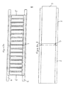
Figure 1a shows a schematic representation of one embodiment of the invention -
Figure 1b shows a side view of the invention ofFigure 1 a -
Figure 2a shows a side view of the invention ofFigure 1a . -
Figure 2b shows a side view of the invention ofFigure 1 a. -
Figure 3a shows a schematic representation of the invention ofFigure 1a . -
Figure 3b shows a schematic representation the invention ofFigure 1a . -
Figure 3c shows a schematic representation of the invention ofFigure 1a . -
Figure 4 shows an alternative embodiment of the invention. -
Figure 5 shows an alternative embodiment of the invention. - As shown in
Figures 1a and 1b , aninsulation support 1 comprisesflanges 2 andtroughs 3. Theflanges 2 may be stapled or nailed into position onjoists 4 or studding in floors, walls and ceilings. -
Insulation material 5 is supported within thetroughs 3. In the embodiment shown inFigure 1 , the apparatus comprises eight troughs. However, the number of troughs maybe varied. In an alternative embodiment theinsulation support 1 may have asingle trough 3. - In a preferred embodiment, each
trough 3 has ribs moulded into it for strength. The base of thetroughs 3 may be solid or may include mesh or other openings to allow the insulation material to breathe. The mesh region may be a plastic type mesh arrangement or, for example, netting material. Similarly, the walls of thetroughs 3 may be solid or include openings as different types of insulation have different properties and requirements. - The
insulation support 1 may also include holes for electrical cables or water pipes. - The
insulation support 1 is preferably made of plastic. Different grades of plastic may be selected according to the particular intended application of the support. In a preferred embodiment, theinsulation support 1 is made of double skinned plastic, with an air gap between inner and outer layers of plastic. A suitable material is fluted polypropylene. - Insulation supports 1 may be coded for different sizes or applications, such that they are readily identifiable. For example, insulation supports may be colour coded so that those for use with floors are blue and those for use with walls are coloured brown.
- In a preferred embodiment, each support is around one metre in length.
- Because floor joists may be spaced at different distances in different buildings and insulation requirements may vary according to the area of type of insulation material, the width and depth of the
supports 1 may be varied. - In use,
insulation material 5 is packed into thetroughs 3 aftersupports 1 have been secured in place on joists or wall studding. This means that insulation can be laid very quickly because there is no need to screw additional supports to the joists. The supports, which are preferably around 1m long, can simply be laid between joists and stapled in place. In this way a large area can be covered very quickly. - Alternatively, the
support 1 andinsulation 5 may be a ready-made unit that can be applied to floors, walls or ceilings in a single step. This means that insulation supports and insulation may be laid directly onto joists simultaneously. - The
insulation 5 is packed tightly against the walls of thetroughs 3, which secures it in position. -
Figure 2a shows a side view of a number ofsupports 1a, 1b, 1c and 1d, holdinginsulation 5 betweenfloor joists 4.Flooring 6 such as wooden flooring is laid over thefloor joists 4. - This arrangement is beneficial because if work needs to be carried out after insulation and/or flooring has been laid, the flooring and/or supports 1 in a particular region can be removed and replaced without affecting insulation under the rest of the floor. If pipes or cables need to be laid in a section of the insulation layer, the
supports 1 can be removed and holes can be drilled in the necessary parts of the supports. - The
supports 1 may have holes pre-drilled in them. - The
supports 1 are arranged in rows betweenfloor joists 4. As illustrated inFigure 2b , theflanges 2 cover substantially the entire width of thejoists 4 andflanges 2 of supports in adjacent rows overlap. In a preferred embodiment eachflange 2 is around 50mm wide. -
Figures 3a and 3b show twoadjacent supports 1' and 1" in the same row. They are positioned between twojoists 4. - The adjacent ends of the
supports 1 in the same row are shaped such that they fit together. At one end of support 1', an extendingportion 7 is arranged to overlap a receiving portion 8 at the end of theadjacent support 1". The length of the extendingportion 7 and hence the region of overlap with the receiving portion 8 is preferably around 50mm. - These
complementary flanges 2 and extending/receivingportions 7,8 make laying the supports in the correct positions easier and ensures that insulation material is evenly distributed.Adjacent flanges 2 may be overlapping and/or interlocking. Similarly, adjacent extendingportions 7 and receiving portions 8 may be shaped such that they overlap and/or interlock. - The
supports 1 may be stackable for storage and theflanges 2 may cooperate in the stacked position to strengthen a stack ofsupports 1. - Sound insulating or sound deadening materials (not shown) may be added to one or more sides of the
supports 1. This could be applied using sound deadening adhesive tape. In a preferred embodiment sound deadening materials are applied to the base of thetrough 3 and to one of theflanges 2. - As shown in
Figure 3c , thesupport 1 is formed from a double skinned material, such as double skinned plastic. This has an inner layer 9 and anouter layer 10. An air gap 11 between the layers of plastic provides additional insulation and the double skinned material is strong such that thesupport 1 will not bend under the weight of insulating material. Extra support and strength is provided byribs 12 between thelayers 9 and 10. The material provides improved rigidity over single layer materials. - The support may be cut or scored to allow folding. Preferably a cut is made in one of the
layers 9 or 10 atpoints 13 shown inFigure 3c . This allows thesupport 1 to be folded for storage, such that the side walls 3' of each trough may be laid flat against the base of thetrough 3 and each of the surfaces 2' of theflanges 2 may be folded down flat against the side walls 3'. This allows supports 1 to be stacked substantially flat against each other when stored. Alternatively, the supports may be stackable in an in use position or in a partially folded position. - When a
support 1 is removed from the flat pack storage position, it is biased such that it assumes the configuration shown inFigure 3c in which it is ready for use. The double skinned material and score lines or cuts facilitate a "pop up" action into an in use position when a support is removed from storage. A cut or score in one surface of the double skinned material weakens it to allow contraction of material about a corresponding point in the opposite surface, which causes the support to assume the "in use" configuration shown inFigure 3c . - The cut or score line causes a weakening at a point in one layer of the double skinned material so that the material about the corresponding point in the opposite surface is of greater strength. In alternative embodiments, the weakening or strengthening of areas of the double skinned material may be created by means other that cuts or score lines, for example, by stamping the material. Furthermore, the cuts or score lines may not be continuous cuts or scores along the material.
- The cut or score line may run parallel to the grain in the plastic sheets. However, this could cause problems during the manufacturing process, since if the cut or score is not precisely parallel and cuts across more than one grain in the plastic, the ability of the sheet to fold may be affected. This may be overcome by manufacturing the
supports 1 by cutting or scoring in a direction perpendicular to the grain of the plastic sheet. - The double skinned plastic provides benefits for acoustic insulation. At the floor joists,
flanges 2 ofadjacent supports 1 over lap, providing twoair gaps 10 in double skinned layers under the floor boards. Because theair gap 10 has insulating properties, less insulation material may need to be added to thetrough 3. - The
support 1 may be made using recycled plastic material. Theflanges 2 may include indicia to show a user where to attach it to joists. - Depending on the building methods used in particular countries, it may be preferable to fit the insulation supports from below the
joists 4. As illustrated inFigure 5 , thesupport 1 may be attached to a joist withflanges 2 on the top surfaces of the joist, or may be attached such that the surfaces 2' of theflanges 2 are attached to the lower surfaces of joists and insulation may be packed into the trough and/or on top of the underside of thetrough 3, between the joists, as shown inFigure 5 . -
Figure 4 shows an alternative embodiment of the invention in which thetrough 3 of thesupport 1 has partial wall or base elements 3'. - In an alternative embodiment the supporting
flanges 2 may be formed separately from thetrough 3. Theflanges 2 may be in the form of hooks or clips that attach to the joists and the side walls of thetroughs 3.
Claims (14)
- Apparatus (1) for supporting insulation comprising a base portion (3), at least one side wall (3') and at least one supporting flange (2'), wherein the apparatus (1) is formed substantially from double skinned material, the double skinned material comprising a first surface layer (10) and a second surface layer (9) and connecting elements between the first and second surface layers, characterized in that the apparatus further comprises at least one cut or score line (13) in the first surface layer between the base (3) and the side wall (3') and at least one cut or score line (13) in the second surface layer (9) between the side wall (3') and the flange (2') wherein in an in use position the at least one side wall (3') is substantially perpendicular to the base portion (3) and the at least one flange (2') is substantially parallel to the base portion (3), and in a storage position the at least one side wall (3') and the at least one flange (2') are substantially parallel to the base portion (3).
- Apparatus as claimed in Claim 1, wherein the apparatus is biased towards the in use position.
- Apparatus as claimed in Claim 1 or 2, wherein the at least one cut or score line (13) facilitates biasing of the apparatus (1) towards the in use position.
- Apparatus as claimed in any preceding claim, wherein the at least one supporting flange (2') is pivotable towards the at least one side wall (3').
- Apparatus as claimed in any preceding claim, wherein the at least one side wall (3') is pivotable towards the base portion (3).
- Apparatus as claimed in any preceding claim, wherein the at least one supporting flange (2') is adapted to engage a structural element of a building.
- Apparatus as claimed in any preceding claim, wherein the apparatus further comprises openings.
- Apparatus as claimed in any preceding claim, further comprising sound deadening elements.
- Apparatus as claimed in any preceding claim wherein the double skinned material is formed of plastic.
- Apparatus as claimed in any preceding claim, further comprising insulating material.
- An insulation system, comprising more than one apparatus for supporting insulation as claimed in any of Claims 1 to 10, wherein the at least one supporting flange (2') of one apparatus (1) is arranged to overlap a supporting flange (2') of an adjacent apparatus (1).
- An insulation system, as claimed in Claim 11, wherein the at least one supporting flange (2') of one apparatus (1) is arranged to interlock with a supporting flange (2') of an adjacent apparatus (1).
- A method of insulating a structure, comprising the steps of:(i) engaging at least one supporting flange (2') of an apparatus (1) for supporting insulation as claimed in any of claims 1 to 10 with a structural element of a building; and(ii) securing the apparatus to the structural element of a building.
- An insulated structure comprising a plurality of support elements, at least one apparatus (1) as claimed in any of claims 1 to 10 and insulating material.
Applications Claiming Priority (3)
| Application Number | Priority Date | Filing Date | Title |
|---|---|---|---|
| GBGB0801981.2A GB0801981D0 (en) | 2008-02-04 | 2008-02-04 | Insulation apparatus and mehtod |
| GB0809626A GB2456883B (en) | 2008-02-04 | 2008-05-28 | Insulation apparatus and method |
| PCT/GB2009/050087 WO2009098499A2 (en) | 2008-02-04 | 2009-01-30 | Insulation apparatus and method |
Publications (2)
| Publication Number | Publication Date |
|---|---|
| EP2252745A2 EP2252745A2 (en) | 2010-11-24 |
| EP2252745B1 true EP2252745B1 (en) | 2014-08-20 |
Family
ID=39204163
Family Applications (1)
| Application Number | Title | Priority Date | Filing Date |
|---|---|---|---|
| EP09707658.2A Active EP2252745B1 (en) | 2008-02-04 | 2009-01-30 | Insulation holder and method |
Country Status (5)
| Country | Link |
|---|---|
| US (1) | US20110036034A1 (en) |
| EP (1) | EP2252745B1 (en) |
| CA (1) | CA2714284A1 (en) |
| GB (3) | GB0801981D0 (en) |
| WO (1) | WO2009098499A2 (en) |
Families Citing this family (13)
| Publication number | Priority date | Publication date | Assignee | Title |
|---|---|---|---|---|
| GB2508878A (en) * | 2012-12-13 | 2014-06-18 | Isomass Ltd | Sound insulating device for location between joists of a floor or ceiling |
| JP6250363B2 (en) * | 2013-11-05 | 2017-12-20 | ダウ化工株式会社 | Rainwater drain insulation board for floor |
| GB201322894D0 (en) * | 2013-12-23 | 2014-02-12 | Robinson Raymond | T-beam saddle |
| US9920516B2 (en) | 2014-02-03 | 2018-03-20 | Owens Corning Intellectual Capital, Llc | Roof insulation systems |
| US9476204B2 (en) | 2014-02-03 | 2016-10-25 | Owens Corning Intellectual Capital, Llc | Boxed netting insulation system for roof deck |
| US9926702B2 (en) | 2014-02-03 | 2018-03-27 | Owens Corning Intellectual Property, LLC | Roof insulation systems |
| JP6727822B2 (en) * | 2016-01-29 | 2020-07-22 | 株式会社コシイプレザービング | Fixture for underfloor insulation |
| US10280613B2 (en) * | 2016-03-23 | 2019-05-07 | Southern Ag Builders & Supply, Llc | Insulation system and method for buildings |
| SE541511C2 (en) | 2017-03-06 | 2019-10-22 | Slaettberg Fredrik | Ready-to-install wall and rule cassettes |
| GB2601514B (en) * | 2020-12-02 | 2023-03-29 | Intumescent Systems Ltd | Fire Rated Wall Panelling for Buildings |
| GB2610638B (en) * | 2021-09-14 | 2026-03-25 | Devana Properties Ltd | An assembly and a method for providing insulation below the floor of a building |
| JP7685242B2 (en) * | 2022-08-30 | 2025-05-29 | ウチヤマコーポレーション株式会社 | Insulation panel holder and insulation panel arrangement structure |
| US12416158B2 (en) * | 2023-07-24 | 2025-09-16 | Speed Rod, Llc | Support structures for insulation and other materials |
Family Cites Families (24)
| Publication number | Priority date | Publication date | Assignee | Title |
|---|---|---|---|---|
| US1894592A (en) * | 1931-07-18 | 1933-01-17 | Charles B Kilmer | Insulating unit |
| US2577588A (en) * | 1946-11-29 | 1951-12-04 | Richard E Paige | Double-walled collapsible carton |
| US2786004A (en) * | 1953-08-07 | 1957-03-19 | Leobarb Corp | Thermal insulation |
| US2782914A (en) * | 1955-08-09 | 1957-02-26 | Jeremiah D Giles | Heat insulation structure |
| US2836293A (en) * | 1955-08-09 | 1958-05-27 | Jeremiah D Giles | Heat insulation structure |
| US2955063A (en) * | 1956-12-04 | 1960-10-04 | Reflectal Corp | Insulating blanket |
| GB2006313B (en) * | 1977-06-23 | 1982-02-17 | Fleischmann A E M | Flooring systems |
| US4125982A (en) * | 1977-09-19 | 1978-11-21 | Ward Bruce K | Floor joist insulation baffle |
| US4292777A (en) * | 1978-10-10 | 1981-10-06 | Story Edward R | Insulation-confining panel and method of using the same |
| GB8710749D0 (en) * | 1987-05-07 | 1987-06-10 | Serpell R J | Self-supporting panels |
| US4972635A (en) * | 1989-01-17 | 1990-11-27 | Wageman Gerald L | Cant vent and rim guard air and moisture stops |
| GB2261448A (en) * | 1991-11-15 | 1993-05-19 | John Martin Greaves | Supporting platform for thermal quilting |
| US5740636A (en) * | 1993-04-19 | 1998-04-21 | Archard; William L. | Weather block and vent |
| GB2279088A (en) * | 1993-06-17 | 1994-12-21 | Derek Albert Lacey | Supporting insulating block between joists |
| GB9612188D0 (en) * | 1996-06-10 | 1996-08-14 | Smith Matthias F | Sound insulation system |
| US6363674B1 (en) * | 1997-11-25 | 2002-04-02 | Tommy Lee Carver | Premanufactured structural building panels |
| DE29722192U1 (en) * | 1997-12-04 | 1998-02-26 | Stone Europa Carton AG, 20095 Hamburg | Corrugated cardboard insulation element for building insulation |
| US6185895B1 (en) * | 1998-12-24 | 2001-02-13 | Robert A. Rettew | Ventilating radiant barrier |
| CA2320590C (en) * | 2000-09-26 | 2005-11-29 | Tim Best | Soffit to attic vent |
| US6622448B1 (en) * | 2001-10-12 | 2003-09-23 | University Of Central Florida | Batt insulation hold-down clips |
| JP3717171B2 (en) * | 2003-05-22 | 2005-11-16 | 松本建工株式会社 | Thermal insulation for housing |
| GB2401884B (en) * | 2003-05-23 | 2007-05-02 | Victor Joseph Wigley | Improvements relating to masonary walls |
| EP1510629A1 (en) * | 2003-08-29 | 2005-03-02 | Rockwool International A/S | Device for securing an insulation board within a cavity wall |
| US6872885B1 (en) * | 2003-12-23 | 2005-03-29 | Hubbell Incorporated | Recessed electrical fixture assembly with insulation barrier and method of using the same |
-
2008
- 2008-02-04 GB GBGB0801981.2A patent/GB0801981D0/en not_active Ceased
- 2008-05-28 GB GB0809626A patent/GB2456883B/en not_active Expired - Fee Related
-
2009
- 2009-01-30 EP EP09707658.2A patent/EP2252745B1/en active Active
- 2009-01-30 WO PCT/GB2009/050087 patent/WO2009098499A2/en not_active Ceased
- 2009-01-30 US US12/735,646 patent/US20110036034A1/en not_active Abandoned
- 2009-01-30 CA CA2714284A patent/CA2714284A1/en not_active Abandoned
-
2010
- 2010-08-20 GB GBGB1013959.0A patent/GB201013959D0/en not_active Ceased
Also Published As
| Publication number | Publication date |
|---|---|
| WO2009098499A2 (en) | 2009-08-13 |
| EP2252745A2 (en) | 2010-11-24 |
| WO2009098499A3 (en) | 2009-10-15 |
| GB0809626D0 (en) | 2008-07-02 |
| US20110036034A1 (en) | 2011-02-17 |
| CA2714284A1 (en) | 2009-08-13 |
| GB0801981D0 (en) | 2008-03-12 |
| GB2456883A (en) | 2009-08-05 |
| GB201013959D0 (en) | 2010-10-06 |
| GB2456883B (en) | 2010-07-21 |
Similar Documents
| Publication | Publication Date | Title |
|---|---|---|
| US20110036034A1 (en) | Insulation apparatus and method | |
| US7654051B2 (en) | Device and method to provide air circulation space proximate to insulation material | |
| US9920516B2 (en) | Roof insulation systems | |
| US8763330B2 (en) | Devices and methods to provide air circulation space proximate to insulation material | |
| US7458189B2 (en) | Device and method to provide air circulation space proximate to insulation material | |
| KR100672867B1 (en) | Aeration Furring Strip | |
| US9926702B2 (en) | Roof insulation systems | |
| US9476204B2 (en) | Boxed netting insulation system for roof deck | |
| US4379381A (en) | Roof insulation system | |
| CA2653494A1 (en) | Moisture drainage spacer panel for building walls | |
| US6279293B1 (en) | Insulated roof panel | |
| US20110209426A1 (en) | Devices and methodd to provide air circulation space proximate to insulation material | |
| US20180044912A1 (en) | Devices and methods to provide air circulation to insulation material | |
| US20170051502A1 (en) | Roof insulation systems | |
| US20090019802A1 (en) | Adjustable insulation containment apparatus | |
| CA1197064A (en) | System for supporting and retaining insulation | |
| CA2938668A1 (en) | Roof insulation systems | |
| US20190376279A1 (en) | Devices and methods to provide air circulation to insulation material | |
| US20130091793A1 (en) | Devices and methods to provide air circulation space proximate to insulation material | |
| US20140311070A1 (en) | Devices and methods to provide air circulation space proximate to insulation material | |
| JPS5847977B2 (en) | insulation sheet | |
| JP2806416B2 (en) | Insulation material for partition wall and method of construction | |
| GB2356855A (en) | Box formed from a blank | |
| JP3488408B2 (en) | Breathable spacer | |
| AU2011100435A4 (en) | A method of installing thermal sub floor insulation |
Legal Events
| Date | Code | Title | Description |
|---|---|---|---|
| PUAI | Public reference made under article 153(3) epc to a published international application that has entered the european phase |
Free format text: ORIGINAL CODE: 0009012 |
|
| 17P | Request for examination filed |
Effective date: 20100906 |
|
| AK | Designated contracting states |
Kind code of ref document: A2 Designated state(s): AT BE BG CH CY CZ DE DK EE ES FI FR GB GR HR HU IE IS IT LI LT LU LV MC MK MT NL NO PL PT RO SE SI SK TR |
|
| AX | Request for extension of the european patent |
Extension state: AL BA RS |
|
| 17Q | First examination report despatched |
Effective date: 20130206 |
|
| GRAP | Despatch of communication of intention to grant a patent |
Free format text: ORIGINAL CODE: EPIDOSNIGR1 |
|
| INTG | Intention to grant announced |
Effective date: 20140304 |
|
| GRAS | Grant fee paid |
Free format text: ORIGINAL CODE: EPIDOSNIGR3 |
|
| GRAA | (expected) grant |
Free format text: ORIGINAL CODE: 0009210 |
|
| AK | Designated contracting states |
Kind code of ref document: B1 Designated state(s): AT BE BG CH CY CZ DE DK EE ES FI FR GB GR HR HU IE IS IT LI LT LU LV MC MK MT NL NO PL PT RO SE SI SK TR |
|
| AX | Request for extension of the european patent |
Extension state: AL BA RS |
|
| REG | Reference to a national code |
Ref country code: GB Ref legal event code: FG4D |
|
| REG | Reference to a national code |
Ref country code: CH Ref legal event code: EP |
|
| REG | Reference to a national code |
Ref country code: AT Ref legal event code: REF Ref document number: 683561 Country of ref document: AT Kind code of ref document: T Effective date: 20140915 |
|
| REG | Reference to a national code |
Ref country code: IE Ref legal event code: FG4D |
|
| REG | Reference to a national code |
Ref country code: DE Ref legal event code: R096 Ref document number: 602009026117 Country of ref document: DE Effective date: 20141002 |
|
| REG | Reference to a national code |
Ref country code: AT Ref legal event code: MK05 Ref document number: 683561 Country of ref document: AT Kind code of ref document: T Effective date: 20140820 |
|
| REG | Reference to a national code |
Ref country code: NL Ref legal event code: VDEP Effective date: 20140820 |
|
| REG | Reference to a national code |
Ref country code: LT Ref legal event code: MG4D |
|
| PG25 | Lapsed in a contracting state [announced via postgrant information from national office to epo] |
Ref country code: PT Free format text: LAPSE BECAUSE OF FAILURE TO SUBMIT A TRANSLATION OF THE DESCRIPTION OR TO PAY THE FEE WITHIN THE PRESCRIBED TIME-LIMIT Effective date: 20141222 Ref country code: FI Free format text: LAPSE BECAUSE OF FAILURE TO SUBMIT A TRANSLATION OF THE DESCRIPTION OR TO PAY THE FEE WITHIN THE PRESCRIBED TIME-LIMIT Effective date: 20140820 Ref country code: SE Free format text: LAPSE BECAUSE OF FAILURE TO SUBMIT A TRANSLATION OF THE DESCRIPTION OR TO PAY THE FEE WITHIN THE PRESCRIBED TIME-LIMIT Effective date: 20140820 Ref country code: ES Free format text: LAPSE BECAUSE OF FAILURE TO SUBMIT A TRANSLATION OF THE DESCRIPTION OR TO PAY THE FEE WITHIN THE PRESCRIBED TIME-LIMIT Effective date: 20140820 Ref country code: LT Free format text: LAPSE BECAUSE OF FAILURE TO SUBMIT A TRANSLATION OF THE DESCRIPTION OR TO PAY THE FEE WITHIN THE PRESCRIBED TIME-LIMIT Effective date: 20140820 Ref country code: NO Free format text: LAPSE BECAUSE OF FAILURE TO SUBMIT A TRANSLATION OF THE DESCRIPTION OR TO PAY THE FEE WITHIN THE PRESCRIBED TIME-LIMIT Effective date: 20141120 Ref country code: GR Free format text: LAPSE BECAUSE OF FAILURE TO SUBMIT A TRANSLATION OF THE DESCRIPTION OR TO PAY THE FEE WITHIN THE PRESCRIBED TIME-LIMIT Effective date: 20141121 Ref country code: BG Free format text: LAPSE BECAUSE OF FAILURE TO SUBMIT A TRANSLATION OF THE DESCRIPTION OR TO PAY THE FEE WITHIN THE PRESCRIBED TIME-LIMIT Effective date: 20141120 |
|
| PG25 | Lapsed in a contracting state [announced via postgrant information from national office to epo] |
Ref country code: LV Free format text: LAPSE BECAUSE OF FAILURE TO SUBMIT A TRANSLATION OF THE DESCRIPTION OR TO PAY THE FEE WITHIN THE PRESCRIBED TIME-LIMIT Effective date: 20140820 Ref country code: AT Free format text: LAPSE BECAUSE OF FAILURE TO SUBMIT A TRANSLATION OF THE DESCRIPTION OR TO PAY THE FEE WITHIN THE PRESCRIBED TIME-LIMIT Effective date: 20140820 Ref country code: IS Free format text: LAPSE BECAUSE OF FAILURE TO SUBMIT A TRANSLATION OF THE DESCRIPTION OR TO PAY THE FEE WITHIN THE PRESCRIBED TIME-LIMIT Effective date: 20141220 Ref country code: HR Free format text: LAPSE BECAUSE OF FAILURE TO SUBMIT A TRANSLATION OF THE DESCRIPTION OR TO PAY THE FEE WITHIN THE PRESCRIBED TIME-LIMIT Effective date: 20140820 |
|
| PG25 | Lapsed in a contracting state [announced via postgrant information from national office to epo] |
Ref country code: NL Free format text: LAPSE BECAUSE OF FAILURE TO SUBMIT A TRANSLATION OF THE DESCRIPTION OR TO PAY THE FEE WITHIN THE PRESCRIBED TIME-LIMIT Effective date: 20140820 |
|
| PG25 | Lapsed in a contracting state [announced via postgrant information from national office to epo] |
Ref country code: CZ Free format text: LAPSE BECAUSE OF FAILURE TO SUBMIT A TRANSLATION OF THE DESCRIPTION OR TO PAY THE FEE WITHIN THE PRESCRIBED TIME-LIMIT Effective date: 20140820 Ref country code: SK Free format text: LAPSE BECAUSE OF FAILURE TO SUBMIT A TRANSLATION OF THE DESCRIPTION OR TO PAY THE FEE WITHIN THE PRESCRIBED TIME-LIMIT Effective date: 20140820 Ref country code: EE Free format text: LAPSE BECAUSE OF FAILURE TO SUBMIT A TRANSLATION OF THE DESCRIPTION OR TO PAY THE FEE WITHIN THE PRESCRIBED TIME-LIMIT Effective date: 20140820 Ref country code: IT Free format text: LAPSE BECAUSE OF FAILURE TO SUBMIT A TRANSLATION OF THE DESCRIPTION OR TO PAY THE FEE WITHIN THE PRESCRIBED TIME-LIMIT Effective date: 20140820 Ref country code: DK Free format text: LAPSE BECAUSE OF FAILURE TO SUBMIT A TRANSLATION OF THE DESCRIPTION OR TO PAY THE FEE WITHIN THE PRESCRIBED TIME-LIMIT Effective date: 20140820 Ref country code: RO Free format text: LAPSE BECAUSE OF FAILURE TO SUBMIT A TRANSLATION OF THE DESCRIPTION OR TO PAY THE FEE WITHIN THE PRESCRIBED TIME-LIMIT Effective date: 20140820 |
|
| REG | Reference to a national code |
Ref country code: DE Ref legal event code: R097 Ref document number: 602009026117 Country of ref document: DE |
|
| PG25 | Lapsed in a contracting state [announced via postgrant information from national office to epo] |
Ref country code: PL Free format text: LAPSE BECAUSE OF FAILURE TO SUBMIT A TRANSLATION OF THE DESCRIPTION OR TO PAY THE FEE WITHIN THE PRESCRIBED TIME-LIMIT Effective date: 20140820 |
|
| PLBE | No opposition filed within time limit |
Free format text: ORIGINAL CODE: 0009261 |
|
| STAA | Information on the status of an ep patent application or granted ep patent |
Free format text: STATUS: NO OPPOSITION FILED WITHIN TIME LIMIT |
|
| PG25 | Lapsed in a contracting state [announced via postgrant information from national office to epo] |
Ref country code: BE Free format text: LAPSE BECAUSE OF NON-PAYMENT OF DUE FEES Effective date: 20150131 |
|
| 26N | No opposition filed |
Effective date: 20150521 |
|
| REG | Reference to a national code |
Ref country code: DE Ref legal event code: R119 Ref document number: 602009026117 Country of ref document: DE |
|
| REG | Reference to a national code |
Ref country code: CH Ref legal event code: PL |
|
| PG25 | Lapsed in a contracting state [announced via postgrant information from national office to epo] |
Ref country code: LU Free format text: LAPSE BECAUSE OF FAILURE TO SUBMIT A TRANSLATION OF THE DESCRIPTION OR TO PAY THE FEE WITHIN THE PRESCRIBED TIME-LIMIT Effective date: 20150130 |
|
| GBPC | Gb: european patent ceased through non-payment of renewal fee |
Effective date: 20150130 |
|
| PG25 | Lapsed in a contracting state [announced via postgrant information from national office to epo] |
Ref country code: MC Free format text: LAPSE BECAUSE OF FAILURE TO SUBMIT A TRANSLATION OF THE DESCRIPTION OR TO PAY THE FEE WITHIN THE PRESCRIBED TIME-LIMIT Effective date: 20140820 |
|
| PG25 | Lapsed in a contracting state [announced via postgrant information from national office to epo] |
Ref country code: DE Free format text: LAPSE BECAUSE OF NON-PAYMENT OF DUE FEES Effective date: 20150801 Ref country code: LI Free format text: LAPSE BECAUSE OF NON-PAYMENT OF DUE FEES Effective date: 20150131 Ref country code: CH Free format text: LAPSE BECAUSE OF NON-PAYMENT OF DUE FEES Effective date: 20150131 Ref country code: GB Free format text: LAPSE BECAUSE OF NON-PAYMENT OF DUE FEES Effective date: 20150130 |
|
| REG | Reference to a national code |
Ref country code: FR Ref legal event code: ST Effective date: 20150930 |
|
| REG | Reference to a national code |
Ref country code: IE Ref legal event code: MM4A |
|
| PG25 | Lapsed in a contracting state [announced via postgrant information from national office to epo] |
Ref country code: SI Free format text: LAPSE BECAUSE OF FAILURE TO SUBMIT A TRANSLATION OF THE DESCRIPTION OR TO PAY THE FEE WITHIN THE PRESCRIBED TIME-LIMIT Effective date: 20140820 Ref country code: FR Free format text: LAPSE BECAUSE OF NON-PAYMENT OF DUE FEES Effective date: 20150202 |
|
| PG25 | Lapsed in a contracting state [announced via postgrant information from national office to epo] |
Ref country code: IE Free format text: LAPSE BECAUSE OF NON-PAYMENT OF DUE FEES Effective date: 20150130 |
|
| PG25 | Lapsed in a contracting state [announced via postgrant information from national office to epo] |
Ref country code: BE Free format text: LAPSE BECAUSE OF FAILURE TO SUBMIT A TRANSLATION OF THE DESCRIPTION OR TO PAY THE FEE WITHIN THE PRESCRIBED TIME-LIMIT Effective date: 20140820 |
|
| PG25 | Lapsed in a contracting state [announced via postgrant information from national office to epo] |
Ref country code: MT Free format text: LAPSE BECAUSE OF FAILURE TO SUBMIT A TRANSLATION OF THE DESCRIPTION OR TO PAY THE FEE WITHIN THE PRESCRIBED TIME-LIMIT Effective date: 20140820 |
|
| PG25 | Lapsed in a contracting state [announced via postgrant information from national office to epo] |
Ref country code: HU Free format text: LAPSE BECAUSE OF FAILURE TO SUBMIT A TRANSLATION OF THE DESCRIPTION OR TO PAY THE FEE WITHIN THE PRESCRIBED TIME-LIMIT; INVALID AB INITIO Effective date: 20090130 |
|
| PG25 | Lapsed in a contracting state [announced via postgrant information from national office to epo] |
Ref country code: CY Free format text: LAPSE BECAUSE OF FAILURE TO SUBMIT A TRANSLATION OF THE DESCRIPTION OR TO PAY THE FEE WITHIN THE PRESCRIBED TIME-LIMIT Effective date: 20140820 |
|
| PG25 | Lapsed in a contracting state [announced via postgrant information from national office to epo] |
Ref country code: TR Free format text: LAPSE BECAUSE OF FAILURE TO SUBMIT A TRANSLATION OF THE DESCRIPTION OR TO PAY THE FEE WITHIN THE PRESCRIBED TIME-LIMIT Effective date: 20140820 |
|
| PG25 | Lapsed in a contracting state [announced via postgrant information from national office to epo] |
Ref country code: MK Free format text: LAPSE BECAUSE OF FAILURE TO SUBMIT A TRANSLATION OF THE DESCRIPTION OR TO PAY THE FEE WITHIN THE PRESCRIBED TIME-LIMIT Effective date: 20140820 |