EP2252080A2 - Domes for a receiver in the canal hearing instrument - Google Patents
Domes for a receiver in the canal hearing instrument Download PDFInfo
- Publication number
- EP2252080A2 EP2252080A2 EP10154278A EP10154278A EP2252080A2 EP 2252080 A2 EP2252080 A2 EP 2252080A2 EP 10154278 A EP10154278 A EP 10154278A EP 10154278 A EP10154278 A EP 10154278A EP 2252080 A2 EP2252080 A2 EP 2252080A2
- Authority
- EP
- European Patent Office
- Prior art keywords
- receiver
- dome
- canal
- ear
- hearing instrument
- Prior art date
- Legal status (The legal status is an assumption and is not a legal conclusion. Google has not performed a legal analysis and makes no representation as to the accuracy of the status listed.)
- Withdrawn
Links
Images

Classifications
-
- H—ELECTRICITY
- H04—ELECTRIC COMMUNICATION TECHNIQUE
- H04R—LOUDSPEAKERS, MICROPHONES, GRAMOPHONE PICK-UPS OR LIKE ACOUSTIC ELECTROMECHANICAL TRANSDUCERS; ELECTRIC HEARING AIDS; PUBLIC ADDRESS SYSTEMS
- H04R25/00—Electric hearing aids
- H04R25/65—Housing parts, e.g. shells, tips or moulds, or their manufacture
- H04R25/652—Ear tips; Ear moulds
-
- H—ELECTRICITY
- H04—ELECTRIC COMMUNICATION TECHNIQUE
- H04R—LOUDSPEAKERS, MICROPHONES, GRAMOPHONE PICK-UPS OR LIKE ACOUSTIC ELECTROMECHANICAL TRANSDUCERS; ELECTRIC HEARING AIDS; PUBLIC ADDRESS SYSTEMS
- H04R25/00—Electric hearing aids
- H04R25/60—Mounting or interconnection of hearing aid parts, e.g. inside tips, housings or to ossicles
- H04R25/604—Mounting or interconnection of hearing aid parts, e.g. inside tips, housings or to ossicles of acoustic or vibrational transducers
-
- H—ELECTRICITY
- H04—ELECTRIC COMMUNICATION TECHNIQUE
- H04R—LOUDSPEAKERS, MICROPHONES, GRAMOPHONE PICK-UPS OR LIKE ACOUSTIC ELECTROMECHANICAL TRANSDUCERS; ELECTRIC HEARING AIDS; PUBLIC ADDRESS SYSTEMS
- H04R25/00—Electric hearing aids
- H04R25/65—Housing parts, e.g. shells, tips or moulds, or their manufacture
-
- H—ELECTRICITY
- H04—ELECTRIC COMMUNICATION TECHNIQUE
- H04R—LOUDSPEAKERS, MICROPHONES, GRAMOPHONE PICK-UPS OR LIKE ACOUSTIC ELECTROMECHANICAL TRANSDUCERS; ELECTRIC HEARING AIDS; PUBLIC ADDRESS SYSTEMS
- H04R2225/00—Details of deaf aids covered by H04R25/00, not provided for in any of its subgroups
- H04R2225/021—Behind the ear [BTE] hearing aids
- H04R2225/0216—BTE hearing aids having a receiver in the ear mould
-
- H—ELECTRICITY
- H04—ELECTRIC COMMUNICATION TECHNIQUE
- H04R—LOUDSPEAKERS, MICROPHONES, GRAMOPHONE PICK-UPS OR LIKE ACOUSTIC ELECTROMECHANICAL TRANSDUCERS; ELECTRIC HEARING AIDS; PUBLIC ADDRESS SYSTEMS
- H04R25/00—Electric hearing aids
- H04R25/65—Housing parts, e.g. shells, tips or moulds, or their manufacture
- H04R25/658—Manufacture of housing parts
Definitions
- a receiver-in-the-canal hearing instrument comprises a receiver inserted into the ear canal, an electronics module, comprising a microphone, amplifier, and battery, and an interconnecting electrical cable.
- the receiver is held in a dome.
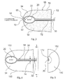
- a receiver-in-the-canal hearing instrument comprising an electronics module 10, a receiver 20 (without a dome), and an interconnecting electrical cable 30, is shown in Figure 1 .
- the electronics module 10 may be configured as a behind-the-ear device, a helix-type device (for the helix of the ear), or any other suitable arrangement.
- a schematic representation of a dome 50 residing adjacent the walls 40 of the ear canal and holding the receiver 20 within a receptacle 52 is shown in Figure 2 .
- the receiver 20 and cable 30 are shown again in a receptacle 52 in a dome 50 in the partial cross-sectional view of Figure 3 , the dome 50 comprising an anterior portion 54 and a posterior portion 56.
- the dome 50 also comprises a tip 60 and a posterior face 62.
- the receptacle 52 is located within the anterior portion 54 of the dome 50, although it could be located elsewhere in the dome 50, such as the geometric center 58 of the dome 50 (determined, e.g., as a function of length and diameter), as depicted schematically by the crossed, dashed lines.
- the size and shape of the receptacle 52 may be selected to conform to the size and shape of the receiver 20, such that the latter is held securely.
- the outer surface 66 of the dome 50 is selected to conform to at least a portion of the user's ear canal walls 40.
- a receiver outlet channel 70 allowing the sound from the outlet 22 (depicted schematically) of the receiver 20 to travel to the tympanic membrane, is located in the anterior portion 54 of the dome 50.
- the receiver outlet channel 70 connects the receptacle 52 to the opening 64 in the tip 60 of the dome 50
- An electrical cable channel 72 is located in the posterior portion 56 of the dome 50, connecting the receptacle 52 with the posterior face 62 of the dome 50.
- the electrical cable channel 72 provides a pathway for the interconnecting electrical cable 30 attached to the receiver 20.
- the diameter or width 74 of the electrical cable channel 72 is selected to conform to or accommodate the outer diameter or width 32 of the electrical cable 30, but is shown much larger in the figures for clarity of presentation (see Figure 4 for elements 32 and 74, indicated by the opposing arrows). As possible design choices, the diameter or width 74 of the electrical cable channel 72 may be approximately equal to or slightly larger than the outer diameter or width 32 of the electrical cable 30.
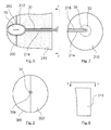
- the dome 50 may be constructed in two complementary halves 150 (or unequal, but complementary, portions), each comprising a receptacle portion 152 and an electrical cable channel portion 172, as illustrated by the elevation and end views of Figures 4 and 5 , respectively, showing one half 150 of the dome 50.
- the two halves 150 are brought together and secured. Any known technique may be utilized to insure proper registration and securement of the two halves 150.
- the dome 50 may be fashioned as an anterior tip section 200 and a posterior section 210, shown in Figures 6 and 7 .
- the receiver 20 is placed first in a receptacle portion 212 in the posterior section 210, while the interconnecting electrical cable 30 is inserted into a slot 214.
- the anterior tip section 200 is then placed over the receiver 20, securing it in place.
- any known technique may be utilized to insure proper registration and securement of the anterior tip and a posterior sections 200 and 210.
- the slot 214 may be closed by inserting a removable closure element 216, illustrated in Figures 7 and 8 .
- the posterior section 210 could be divided into two complementary halves 300 and 302, shown in Figure 9 , obviating the need for the slot 214.
- a channel 304 (comprising two complementary channel portions) would be provided to accommodate and hold the interconnecting electrical cable 30.
- the dome 50 may be fabricated utilizing known techniques for sizing, modeling, and fabricating the outer surfaces of a hearing instrument shell, such as described in U.S. Patent Application Publication No. 2002/0196954 A1, published Dec. 26, 2002 and titled, "Modeling and fabrication of three-dimensional irregular surfaces for hearing instruments," incorporated here by reference. Further, the dome 50 may be fabricated using materials that result in hardness ratings ranging from 50 on the Shore A scale to 80-85 on the Shore D scale. A commercially-available apparatus that may be employed for fabrication of the dome 50 is the Connex500 printing system manufactured by Objet Geometries Ltd., Rehovot, Israel.
Landscapes
- Engineering & Computer Science (AREA)
- Health & Medical Sciences (AREA)
- General Health & Medical Sciences (AREA)
- Neurosurgery (AREA)
- Otolaryngology (AREA)
- Physics & Mathematics (AREA)
- Acoustics & Sound (AREA)
- Signal Processing (AREA)
- Manufacturing & Machinery (AREA)
- Headphones And Earphones (AREA)
- Investigating Or Analyzing Materials By The Use Of Ultrasonic Waves (AREA)
Abstract
Description
- A receiver-in-the-canal hearing instrument comprises a receiver inserted into the ear canal, an electronics module, comprising a microphone, amplifier, and battery, and an interconnecting electrical cable. The receiver is held in a dome.
- To remove the receiver from the canal, users typically pull on the electrical cable, occasionally dislodging the receiver from the dome. To prevent this from happening, a receptacle that securely holds the receiver is created within the dome.
-
-
Figure 1 is a drawing of a receiver-in-the-canal hearing instrument, comprising a receiver, an electronics module, and an interconnecting electrical cable; -
Figure 2 is a schematic drawing of a dome with a receptacle for the receiver ofFigure 1 and the interconnecting electrical cable; -
Figure 3 is a partial cross-sectional view of the dome ofFigure 2 ; -
Figures 4 and 5 are elevation and end views of one-half of a dome; -
Figures 6 and 7 are cross-sectional and end views of a dome comprising anterior tip and posterior sections; -
Figure 8 is a drawing of a closure element for the posterior section ofFigures 6 and 7 ; and -
Figure 9 is an end view of the posterior section ofFigures 6 and 7 , where the posterior section is subdivided into complementary halves. - A receiver-in-the-canal hearing instrument, comprising an
electronics module 10, a receiver 20 (without a dome), and an interconnectingelectrical cable 30, is shown inFigure 1 . Theelectronics module 10 may be configured as a behind-the-ear device, a helix-type device (for the helix of the ear), or any other suitable arrangement. A schematic representation of adome 50 residing adjacent thewalls 40 of the ear canal and holding thereceiver 20 within areceptacle 52 is shown inFigure 2 . - The
receiver 20 andcable 30 are shown again in areceptacle 52 in adome 50 in the partial cross-sectional view ofFigure 3 , thedome 50 comprising ananterior portion 54 and aposterior portion 56. Thedome 50 also comprises atip 60 and aposterior face 62. In this figure, thereceptacle 52 is located within theanterior portion 54 of thedome 50, although it could be located elsewhere in thedome 50, such as thegeometric center 58 of the dome 50 (determined, e.g., as a function of length and diameter), as depicted schematically by the crossed, dashed lines. The size and shape of thereceptacle 52 may be selected to conform to the size and shape of thereceiver 20, such that the latter is held securely. Theouter surface 66 of thedome 50 is selected to conform to at least a portion of the user'sear canal walls 40. - A
receiver outlet channel 70, allowing the sound from the outlet 22 (depicted schematically) of thereceiver 20 to travel to the tympanic membrane, is located in theanterior portion 54 of thedome 50. Thereceiver outlet channel 70 connects thereceptacle 52 to theopening 64 in thetip 60 of thedome 50 Anelectrical cable channel 72 is located in theposterior portion 56 of thedome 50, connecting thereceptacle 52 with theposterior face 62 of thedome 50. Theelectrical cable channel 72 provides a pathway for the interconnectingelectrical cable 30 attached to thereceiver 20. The diameter orwidth 74 of theelectrical cable channel 72 is selected to conform to or accommodate the outer diameter orwidth 32 of theelectrical cable 30, but is shown much larger in the figures for clarity of presentation (seeFigure 4 forelements width 74 of theelectrical cable channel 72 may be approximately equal to or slightly larger than the outer diameter orwidth 32 of theelectrical cable 30. - The
dome 50 may be constructed in two complementary halves 150 (or unequal, but complementary, portions), each comprising areceptacle portion 152 and an electricalcable channel portion 172, as illustrated by the elevation and end views ofFigures 4 and 5 , respectively, showing onehalf 150 of thedome 50. After thereceiver 20 is placed in thereceptacle portion 152, the twohalves 150 are brought together and secured. Any known technique may be utilized to insure proper registration and securement of the twohalves 150. - As an alternative to the two
halves 150, thedome 50 may be fashioned as ananterior tip section 200 and aposterior section 210, shown inFigures 6 and 7 . To assemble the dome, thereceiver 20 is placed first in areceptacle portion 212 in theposterior section 210, while the interconnectingelectrical cable 30 is inserted into aslot 214. Theanterior tip section 200 is then placed over thereceiver 20, securing it in place. Again, any known technique may be utilized to insure proper registration and securement of the anterior tip and aposterior sections slot 214 may be closed by inserting aremovable closure element 216, illustrated inFigures 7 and 8 . - As yet a further alternative to the configuration of
Figures 6 and 7 , theposterior section 210 could be divided into twocomplementary halves Figure 9 , obviating the need for theslot 214. Instead, a channel 304 (comprising two complementary channel portions) would be provided to accommodate and hold the interconnectingelectrical cable 30. - If desired, the
dome 50 may be fabricated utilizing known techniques for sizing, modeling, and fabricating the outer surfaces of a hearing instrument shell, such as described inU.S. Patent Application Publication No. 2002/0196954 A1, published Dec. 26, 2002 and titled, "Modeling and fabrication of three-dimensional irregular surfaces for hearing instruments," incorporated here by reference. Further, thedome 50 may be fabricated using materials that result in hardness ratings ranging from 50 on the Shore A scale to 80-85 on the Shore D scale. A commercially-available apparatus that may be employed for fabrication of thedome 50 is the Connex500 printing system manufactured by Objet Geometries Ltd., Rehovot, Israel.
Claims (13)
- An ear-canal dome for receiving and retaining an in-the-canal hearing instrument receiver and an electrical connecting cable connected to the receiver and an electronics module, for insertion into the ear canal of the user, the dome comprising:an outer surface conforming to at least a portion of the user's ear canal;an anterior portion comprising a tip oriented towards the inner ear, the tip comprising an opening;a posterior portion comprising a posterior surface oriented towards the outer ear, the posterior surface comprising an opening;a receptacle for selectively receiving and retaining the receiver;a first channel connecting the receptacle to the opening in the tip; anda second channel connecting the receptacle and the opening in the posterior surface, the second channel selectively receiving and retaining the electrical connecting cable.
- An ear-canal dome as set forth in claim 1, where the diameter or width of the second channel is approximately equal to the diameter or width of the outer surface of the electrical connecting cable.
- An ear-canal dome as set forth in claim 1, where the receptacle is positioned in the anterior portion of the dome.
- An ear-canal dome as set forth in claim 1, where the dome comprises two complementary portions.
- An ear-canal dome as set forth in claim 4, where the two complementary portions are complementary halves.
- An ear-canal dome as set forth in claim 1, where the dome comprises an anterior tip section and posterior section.
- A receiver-in-the-canal hearing instrument, comprising:an in-the-canal hearing instrument receiver;an electrical connecting cable connecting the receiver to an electronics module; andan ear-canal dome for receiving and retaining an in-the-canal hearing instrument receiver and the electrical connecting cable, for insertion into the ear canal of the user, the dome comprisingan outer surface conforming to at least a portion of the user's ear canal;an anterior portion comprising a tip oriented towards the inner ear, the tip comprising an opening;a posterior portion comprising a posterior surface oriented towards the outer ear, the posterior surface comprising an opening;a receptacle for selectively receiving and retaining the receiver;a first channel connecting the receptacle to the opening in the tip; anda second channel connecting the receptacle and the opening in the posterior surface, the second channel selectively receiving and retaining the electrical connecting cable.
- A receiver-in-the-canal hearing instrument as set forth in claim 7, where the diameter or width of the second channel is approximately equal to the diameter or width of the outer surface of the electrical connecting cable.
- A receiver-in-the-canal hearing instrument as set forth in claim 7, where the receptacle is positioned in the anterior portion of the dome.
- A receiver-in-the-canal hearing instrument as set forth in claim 7, where the dome comprises two complementary portions.
- A receiver-in-the-canal hearing instrument as set forth in claim 10, where the two complementary portions are complementary halves.
- A receiver-in-the-canal hearing instrument as set forth in claim 7, where the dome comprises an anterior tip section and posterior section.
- A receiver-in-the-canal hearing instrument as set forth in claim 7, further comprising an electronics module.
Applications Claiming Priority (1)
| Application Number | Priority Date | Filing Date | Title |
|---|---|---|---|
| US12/465,696 US9185503B2 (en) | 2009-05-14 | 2009-05-14 | Domes for a receiver-in-the-canal hearing instrument |
Publications (2)
| Publication Number | Publication Date |
|---|---|
| EP2252080A2 true EP2252080A2 (en) | 2010-11-17 |
| EP2252080A3 EP2252080A3 (en) | 2013-06-05 |
Family
ID=42562936
Family Applications (1)
| Application Number | Title | Priority Date | Filing Date |
|---|---|---|---|
| EP10154278.5A Withdrawn EP2252080A3 (en) | 2009-05-14 | 2010-02-22 | Domes for a receiver in the canal hearing instrument |
Country Status (2)
| Country | Link |
|---|---|
| US (1) | US9185503B2 (en) |
| EP (1) | EP2252080A3 (en) |
Citations (1)
| Publication number | Priority date | Publication date | Assignee | Title |
|---|---|---|---|---|
| US20020196954A1 (en) | 2001-06-22 | 2002-12-26 | Marxen Christopher J. | Modeling and fabrication of three-dimensional irregular surfaces for hearing instruments |
Family Cites Families (11)
| Publication number | Priority date | Publication date | Assignee | Title |
|---|---|---|---|---|
| US4073366A (en) | 1976-07-26 | 1978-02-14 | Estes Roger Q | Disposable noise reducing hearing aid attachment |
| JPS62151100A (en) | 1985-12-25 | 1987-07-06 | Matsushita Electric Ind Co Ltd | hearing aid |
| US5694475A (en) | 1995-09-19 | 1997-12-02 | Interval Research Corporation | Acoustically transparent earphones |
| US7664282B2 (en) * | 1998-11-25 | 2010-02-16 | Insound Medical, Inc. | Sealing retainer for extended wear hearing devices |
| US7227968B2 (en) * | 2001-06-25 | 2007-06-05 | Sonion Roskilde A/S | Expandsible Receiver Module |
| US7110562B1 (en) | 2001-08-10 | 2006-09-19 | Hear-Wear Technologies, Llc | BTE/CIC auditory device and modular connector system therefor |
| US7141014B2 (en) | 2002-03-20 | 2006-11-28 | Siemens Hearing Instruments, Inc. | Cushioning device for use with a hearing aid |
| DK1594340T3 (en) * | 2004-05-03 | 2012-08-27 | Gn Resound As | Flexible earpiece for a hearing aid |
| US7477756B2 (en) | 2006-03-02 | 2009-01-13 | Knowles Electronics, Llc | Isolating deep canal fitting earphone |
| WO2008095489A1 (en) | 2007-02-08 | 2008-08-14 | Widex A/S | Receiver in the ear (rite) component for a hearing aid |
| US20090116672A1 (en) | 2007-11-01 | 2009-05-07 | Dave Prahl | Instant custom ear mold with removable receiver insert for auditory devices |
-
2009
- 2009-05-14 US US12/465,696 patent/US9185503B2/en not_active Expired - Fee Related
-
2010
- 2010-02-22 EP EP10154278.5A patent/EP2252080A3/en not_active Withdrawn
Patent Citations (1)
| Publication number | Priority date | Publication date | Assignee | Title |
|---|---|---|---|---|
| US20020196954A1 (en) | 2001-06-22 | 2002-12-26 | Marxen Christopher J. | Modeling and fabrication of three-dimensional irregular surfaces for hearing instruments |
Also Published As
| Publication number | Publication date |
|---|---|
| US9185503B2 (en) | 2015-11-10 |
| EP2252080A3 (en) | 2013-06-05 |
| US20100290656A1 (en) | 2010-11-18 |
Similar Documents
| Publication | Publication Date | Title |
|---|---|---|
| AU2009357228B2 (en) | An ear plug for a hearing aid and a hearing aid | |
| US7844065B2 (en) | Hearing instrument | |
| DK2443842T3 (en) | Hearing aid with a replaceable insert cap | |
| US9258657B2 (en) | Method of manufacturing a soft custom ear mold and a soft custom ear mold | |
| US20110188690A1 (en) | Receiver in concha | |
| EP1681904B1 (en) | Hearing instrument | |
| EP1272003B1 (en) | An expansible receiver module | |
| US20090082801A1 (en) | Tool for inserting a receiver of a hearing apparatus into an auditory canal | |
| US20080304674A1 (en) | Hearing device test adapter | |
| US8290187B2 (en) | Hearing device and earpiece therefore | |
| EP2091267A1 (en) | Receiver module for a hearing device, hearing device and hearing device earpiece | |
| US9185503B2 (en) | Domes for a receiver-in-the-canal hearing instrument | |
| EP2309779B1 (en) | Hearing device and earpiece | |
| EP2876904B1 (en) | Hearing aid having receiver | |
| EP4412253A1 (en) | Ite hearing device with microphone protector element | |
| WO2025252820A1 (en) | Custom-made in-ear audio assembly | |
| EP3086573B1 (en) | A hearing device configured to be placed in the ear canal of a user |
Legal Events
| Date | Code | Title | Description |
|---|---|---|---|
| PUAI | Public reference made under article 153(3) epc to a published international application that has entered the european phase |
Free format text: ORIGINAL CODE: 0009012 |
|
| AK | Designated contracting states |
Kind code of ref document: A2 Designated state(s): AT BE BG CH CY CZ DE DK EE ES FI FR GB GR HR HU IE IS IT LI LT LU LV MC MK MT NL NO PL PT RO SE SI SK SM TR |
|
| AX | Request for extension of the european patent |
Extension state: AL BA RS |
|
| PUAL | Search report despatched |
Free format text: ORIGINAL CODE: 0009013 |
|
| AK | Designated contracting states |
Kind code of ref document: A3 Designated state(s): AT BE BG CH CY CZ DE DK EE ES FI FR GB GR HR HU IE IS IT LI LT LU LV MC MK MT NL NO PL PT RO SE SI SK SM TR |
|
| AX | Request for extension of the european patent |
Extension state: AL BA RS |
|
| RIC1 | Information provided on ipc code assigned before grant |
Ipc: H04R 25/00 20060101AFI20130429BHEP |
|
| 17P | Request for examination filed |
Effective date: 20140116 |
|
| RBV | Designated contracting states (corrected) |
Designated state(s): AT BE BG CH CY CZ DE DK EE ES FI FR GB GR HR HU IE IS IT LI LT LU LV MC MK MT NL NO PL PT RO SE SI SK SM TR |
|
| RAP1 | Party data changed (applicant data changed or rights of an application transferred) |
Owner name: SIEMENS MEDICAL INSTRUMENTS PTE. LTD. |
|
| RAP1 | Party data changed (applicant data changed or rights of an application transferred) |
Owner name: SIVANTOS PTE. LTD. |
|
| 17Q | First examination report despatched |
Effective date: 20160602 |
|
| STAA | Information on the status of an ep patent application or granted ep patent |
Free format text: STATUS: EXAMINATION IS IN PROGRESS |
|
| RAP1 | Party data changed (applicant data changed or rights of an application transferred) |
Owner name: SIVANTOS PTE. LTD. |
|
| STAA | Information on the status of an ep patent application or granted ep patent |
Free format text: STATUS: THE APPLICATION IS DEEMED TO BE WITHDRAWN |
|
| 18D | Application deemed to be withdrawn |
Effective date: 20180301 |