EP2251950A2 - Desk box - Google Patents
Desk box Download PDFInfo
- Publication number
- EP2251950A2 EP2251950A2 EP10159778A EP10159778A EP2251950A2 EP 2251950 A2 EP2251950 A2 EP 2251950A2 EP 10159778 A EP10159778 A EP 10159778A EP 10159778 A EP10159778 A EP 10159778A EP 2251950 A2 EP2251950 A2 EP 2251950A2
- Authority
- EP
- European Patent Office
- Prior art keywords
- holder
- desk box
- lid
- abutment frame
- electric
- Prior art date
- Legal status (The legal status is an assumption and is not a legal conclusion. Google has not performed a legal analysis and makes no representation as to the accuracy of the status listed.)
- Granted
Links
- 125000006850 spacer group Chemical group 0.000 claims description 3
- 239000000428 dust Substances 0.000 description 2
- 239000000725 suspension Substances 0.000 description 2
- 244000043261 Hevea brasiliensis Species 0.000 description 1
- XAGFODPZIPBFFR-UHFFFAOYSA-N aluminium Chemical compound [Al] XAGFODPZIPBFFR-UHFFFAOYSA-N 0.000 description 1
- 229910052782 aluminium Inorganic materials 0.000 description 1
- 239000004411 aluminium Substances 0.000 description 1
- 230000015572 biosynthetic process Effects 0.000 description 1
- 230000001419 dependent effect Effects 0.000 description 1
- 239000007788 liquid Substances 0.000 description 1
- 229920003052 natural elastomer Polymers 0.000 description 1
- 229920001194 natural rubber Polymers 0.000 description 1
- 230000000149 penetrating effect Effects 0.000 description 1
- 229920000642 polymer Polymers 0.000 description 1
Images
Classifications
-
- H—ELECTRICITY
- H02—GENERATION; CONVERSION OR DISTRIBUTION OF ELECTRIC POWER
- H02G—INSTALLATION OF ELECTRIC CABLES OR LINES, OR OF COMBINED OPTICAL AND ELECTRIC CABLES OR LINES
- H02G3/00—Installations of electric cables or lines or protective tubing therefor in or on buildings, equivalent structures or vehicles
- H02G3/02—Details
- H02G3/08—Distribution boxes; Connection or junction boxes
- H02G3/12—Distribution boxes; Connection or junction boxes for flush mounting
- H02G3/128—Distribution boxes; Connection or junction boxes for flush mounting in plinths, channels, raceways or similar
-
- A—HUMAN NECESSITIES
- A47—FURNITURE; DOMESTIC ARTICLES OR APPLIANCES; COFFEE MILLS; SPICE MILLS; SUCTION CLEANERS IN GENERAL
- A47B—TABLES; DESKS; OFFICE FURNITURE; CABINETS; DRAWERS; GENERAL DETAILS OF FURNITURE
- A47B21/00—Tables or desks for office equipment, e.g. typewriters, keyboards
- A47B21/06—Tables or desks for office equipment, e.g. typewriters, keyboards characterised by means for holding, fastening or concealing cables
-
- H—ELECTRICITY
- H02—GENERATION; CONVERSION OR DISTRIBUTION OF ELECTRIC POWER
- H02G—INSTALLATION OF ELECTRIC CABLES OR LINES, OR OF COMBINED OPTICAL AND ELECTRIC CABLES OR LINES
- H02G3/00—Installations of electric cables or lines or protective tubing therefor in or on buildings, equivalent structures or vehicles
- H02G3/02—Details
- H02G3/08—Distribution boxes; Connection or junction boxes
- H02G3/18—Distribution boxes; Connection or junction boxes providing line outlets
- H02G3/185—Floor outlets and access cups
-
- A—HUMAN NECESSITIES
- A47—FURNITURE; DOMESTIC ARTICLES OR APPLIANCES; COFFEE MILLS; SPICE MILLS; SUCTION CLEANERS IN GENERAL
- A47B—TABLES; DESKS; OFFICE FURNITURE; CABINETS; DRAWERS; GENERAL DETAILS OF FURNITURE
- A47B2200/00—General construction of tables or desks
- A47B2200/008—Tables or desks having means for applying electronic or electric devices
- A47B2200/0082—Cable inlet in worktop or desk, e.g. grommet
Definitions
- the present invention relates to the area of desk boxes recessed in table tops for electric, tele- and data socket connections.
- the patent specification JP 8008005 discloses a desk box that is formed with a holder provided with an abutment frame, which holder is mounted recessed in a table top. In the holder, an electric insert is mounted that is provided with two switch-in connections.
- This desk box is further provided with two hinged doors that are opened and closed against each other so that they form a transverse slit across the box. When one plug is connected to this box, at least one of the doors has to be open, and when two plugs are connected, both doors have to be open.
- the present invention aims at providing a desk box for electric, tele- and data socket connections that is user-friendly, reasonably liquid-proof as well as plane and concealed from the upperside of a table surface also during use.
- a further object of the invention is to provide a space in the box in order to, at least partly, receive electric cables that are connected to the desk box.
- an object of the invention is to enable a desk box that further provides the possibility of connection of electric wires from below.
- the invention concerns a desk box comprising fastening members to fix the desk box in a table top. It also comprises an essentially rectangular abutment frame that is arranged to abut against the table top as well as a lid placed over an opening formed by the abutment frame in the desk box. When the lid is closed, the desk box obtains an essentially plane geometry also when electric cables are connected.
- the desk box further comprises a first end wall connected to a first short side of the abutment frame and a second end wall connected to a second short side of the abutment frame, a holder being mounted in said end walls. In this connection, the holder is arranged to carry at least one first electric insert to which external electric equipment is connectable by said cables.
- the holder is formed with first mounting members in which the first electric insert is detachably mounted, the holder being mounted to the end walls at an angle in the interval of 30°-60° , preferably 45°, in relation to the abutment frame so that also the first electric insert obtains the same angle in relation to the abutment frame and thereby the table top.
- This angled position of the holder and the electric inserts means that a space is created inside the desk box in order to receive the plugs and encase cable connections also when the lid is closed.
- the holder is provided with second mounting members that are counter-directed to said first mounting members so that at least one second electric insert also can be detachably mounted in the holder for the connection of external electric equipment from the opposite side of the holder.
- second mounting members By virtue of said second mounting members, a double-sided mounting of the electric inserts is obtained so that consumers also can be connected from the underside of the table.
- the holder is formed as a section provided with longitudinal grooves and in which the electric inserts can be continuously variably mounted along the section.
- the holder By forming the holder as a section having longitudinal grooves, a plurality of electric inserts of different widths can be mounted at optional locations along the section. Also cover lids can be mounted at locations where no insert is mounted in order to obtain a protection against cables penetrating into the section.
- the lid is provided with a compliant means that connects to the long side of the abutment frame.
- the compliant means allows cables to be connected to the desk box in spite of the door being closed, thereby preventing dust and objects from coming down into the box.
- the underside of the lid is connected to a hinge mechanism that is mounted to the long side of the abutment frame so that said mechanism is concealed when the lid is closed.
- the hinge mechanism is preferably of the type where a push at the front edge of the lid opens a closed lid and where the lid is closed by pressing the lid downward into closed position in which it stops.
- the concealed mechanism means that the desk box is essentially plane on a level with the table surface both without and with cables connected.
- the compliant means is provided with an edge bulge adapted to a groove in the lid in order to thereby be mountable on the lid by the edge bulge being inserted into the groove. That the mounting of the means is carried out in this way implies that the means can be easily replaced, e.g., if the connection thereof to the abutment frame has been deformed or if the present means is to be replaced by another type of means.
- said compliant means is formed either as an elastic edge or as a brush-shaped edge in order for the lid, as far as possible, to connect to the abutment frame when electric wires run out from the desk box.
- An elastic edge results in a good dust protection with closed door, while a brush-shaped edge results in a plane surface of the box at connected cables. Accordingly, the edge of the lid can be adapted to a specific use of the box.
- said holder is formed to carry a plurality of electric inserts, cover means or spacer means.
- a "long" holder in a “long” desk box many electric inserts can be mounted and used simultaneously, which in certain cases is desirable.
- Voltage feed may be used together with broadband, telephones and conference equipment in one and the same desk box, which means a wide field of application.
- the invention concerns a desk box comprising at least one electric insert, but often a plurality, to which electric products can be connected from both the front side and the back side of the insert.
- the insert is placed in a connection cavity in the desk box at an angle so that a space for plugs is formed at the upperside of the inserts in order to allow a lid to be connectable when electric consumers are connected to the inserts.
- Fastening members are arranged to fit the desk box in a table top.
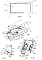
- Figure 1 shows a desk box 10 that is embeddedly mounted in a table top 12.
- the desk box is covered by a lid 13 that is provided with a compliant means 14 that connects to a rectangular abutment frame 15, which abuts flatly against the table top.
- the compliant means 14 may be manufactured from a soft polymer or be of natural rubber and be formed tapering toward the abutment edge 16 thereof.
- the lid is further raiseable by it being provided with a hinge mechanism at the opposite edge 17 of the abutment edge 16.
- the abutment frame, and thereby the desk box is formed with opposite long sides and opposite short sides orientated perpendicular to each other.
- the desk box obtains a plane position almost on a level with the surface of the table top, which gives the table a dean and tidy look at the same time as papers, books, etc., even can be placed on top of the desk box.
- FIG. 2 shows the desk box 10 according to the invention with the lid 13 dismounted from a hinge mechanism 20 that consists of two parts placed internally at each side of the abutment frame 15.
- the desk box comprises a first end wall 21 connected to a first short side 211 of the abutment frame and a second end wall 22 connected to a second short side 222 of the abutment frame.
- the end walls 21, 22 are connected with a first supporting edge 23 along a first long side 231 of the abutment frame and with a second supporting edge 24 along a second long side 241 of the abutment frame.
- a holder 25 is fixedly mounted, which holder is arranged to carry one or more electric inserts 261, 262.
- the figure shows electric inserts in the form of an earthed voltage socket 261 and double data sockets 262.
- the holder furthermore, beside the electric inserts, carries a cover means 27a in order to conceal the inside of the holder when only a few inserts are mounted as well as a spacer means 27b to provide a defined distance between the adjacent inserts.
- the desk box is further provided with suspension members 28 that are for attachment of a basket, not shown, that can hang under the desk box to take care of so-called cable slack.
- the suspension members constitute a bent end part of the supporting edges 32, 24.
- the figure also shows the compliant means 14, which is provided with an edge bulge 29 inserted into a groove 30 in the lid 13.
- Figure 3 shows the desk box from the side with the first end wall 21 connected to the first short side 211 of the abutment frame. Furthermore, the first supporting edge 23 and the second supporting edge 24 are shown.
- the first end wall 21 is provided with a quadratic slot 31 in order to allow the electric inserts mounted in the holder to be electrically connected via connectors 32.
- the figure also shows that the holder is fixed at the end walls by four rivets 331, 332, 333, 334 at each end of the holder.
- FIG 4 shows the desk box 10 from the underside with the holder 25 mounted in the two end walls 21, 22.
- the electric inserts are mountable to the second side of the holder 25 and the figure shows a second voltage socket 42 in which plugs can be connected from the underside of the desk box.
- the back side of this socket is covered, that is seen in Figure 2 , by the cover lid 27.
- cover lids may also be connected to the underside of the holder in order to also cover the back side of the earthed voltage socket 261 and the double data socket 262, which both are accessible from the upperside of the desk box.
- the holder 25 is formed as an aluminium section in two pieces that is provided with longitudinal grooves placed at the front side of the section in the form of first mounting members 45a as well as at the back side of the section in the form of second mounting members 45b so that the electric inserts can be continuously variably placed optionally along the section.
- Figures 2-4 show that the holder 25 is mounted at an angle ⁇ in relation to the underside of the abutment frame 15 and thereby to the table top as well as mounted nearer the second long side 241 of the abutment frame than the first long side 231 thereof.
- the angle is preferably approx. 45° but may assume any angle in the interval of 30°-60° .
- This mounting means that a wedge-shaped space volume 43 is created in the desk box when the lid including the compliant means 14 thereof is closed.
- the wedge-shaped space volume means that electric plugs can be connected to the electric inserts in spite of the lid being closed.
- the space volume together with an opening 44 in the desk box underneath between the holder 25 and the first supporting edge 23 gives also a possibility of hiding away the cables connected from the upperside.
- the figure shows fastening members 46 for the fixing of the desk box in the table top.
- the fastening members 46 are placed on the end walls 21, 22 and have the shape of a lying bottle.
- the mounting of an attachment for the fastening member 46 is made by introducing the attachment into the larger part of the opening and then pushing it laterally to the smaller part of the opening.
- On the attachment there is a screw mounted and when the same is tightened, it meets the underside of the table top, thereby attaching the desk box.
Landscapes
- Engineering & Computer Science (AREA)
- Architecture (AREA)
- Civil Engineering (AREA)
- Structural Engineering (AREA)
- Tables And Desks Characterized By Structural Shape (AREA)
- Cosmetics (AREA)
Abstract
Description
- The present invention relates to the area of desk boxes recessed in table tops for electric, tele- and data socket connections.
- In public environments, there is a need of temporary connecting products such as, e.g., vacuum cleaners, computers, conference equipment and telephones. This may, e.g., be carried out by mounting a desk box in an existing table top and connecting the electric products to this desk box.
- The patent specification
JP 8008005 - When a plug is connected to such a desk box, accordingly at least one door will always be open, which means that the plug is sticking up above the table surface and may thereby be subjected to knocks and impacts that may give rise to loose connection and spark formation. In addition, the plug becomes immediately exposed to liquids that by accident may be spilled on the table.
- The present invention aims at providing a desk box for electric, tele- and data socket connections that is user-friendly, reasonably liquid-proof as well as plane and concealed from the upperside of a table surface also during use.
- A further object of the invention is to provide a space in the box in order to, at least partly, receive electric cables that are connected to the desk box.
- In addition, an object of the invention is to enable a desk box that further provides the possibility of connection of electric wires from below.
- By the present invention such as the same is defined in the independent claim, the above-mentioned object is met. Suitable embodiments of the invention are defined in the dependent claims.
- The invention concerns a desk box comprising fastening members to fix the desk box in a table top. It also comprises an essentially rectangular abutment frame that is arranged to abut against the table top as well as a lid placed over an opening formed by the abutment frame in the desk box. When the lid is closed, the desk box obtains an essentially plane geometry also when electric cables are connected. The desk box further comprises a first end wall connected to a first short side of the abutment frame and a second end wall connected to a second short side of the abutment frame, a holder being mounted in said end walls. In this connection, the holder is arranged to carry at least one first electric insert to which external electric equipment is connectable by said cables. The holder is formed with first mounting members in which the first electric insert is detachably mounted, the holder being mounted to the end walls at an angle in the interval of 30°-60° , preferably 45°, in relation to the abutment frame so that also the first electric insert obtains the same angle in relation to the abutment frame and thereby the table top. This angled position of the holder and the electric inserts means that a space is created inside the desk box in order to receive the plugs and encase cable connections also when the lid is closed.
- In further embodiments of the invention, the holder is provided with second mounting members that are counter-directed to said first mounting members so that at least one second electric insert also can be detachably mounted in the holder for the connection of external electric equipment from the opposite side of the holder. By virtue of said second mounting members, a double-sided mounting of the electric inserts is obtained so that consumers also can be connected from the underside of the table.
- In further embodiments of the invention, the holder is formed as a section provided with longitudinal grooves and in which the electric inserts can be continuously variably mounted along the section. By forming the holder as a section having longitudinal grooves, a plurality of electric inserts of different widths can be mounted at optional locations along the section. Also cover lids can be mounted at locations where no insert is mounted in order to obtain a protection against cables penetrating into the section.
- In further embodiments of the invention, the lid is provided with a compliant means that connects to the long side of the abutment frame. The compliant means allows cables to be connected to the desk box in spite of the door being closed, thereby preventing dust and objects from coming down into the box.
- In further embodiments of the invention, the underside of the lid is connected to a hinge mechanism that is mounted to the long side of the abutment frame so that said mechanism is concealed when the lid is closed. The hinge mechanism is preferably of the type where a push at the front edge of the lid opens a closed lid and where the lid is closed by pressing the lid downward into closed position in which it stops. The concealed mechanism means that the desk box is essentially plane on a level with the table surface both without and with cables connected.
- In further embodiments of the invention, the compliant means is provided with an edge bulge adapted to a groove in the lid in order to thereby be mountable on the lid by the edge bulge being inserted into the groove. That the mounting of the means is carried out in this way implies that the means can be easily replaced, e.g., if the connection thereof to the abutment frame has been deformed or if the present means is to be replaced by another type of means.
- In further embodiments of the invention, said compliant means is formed either as an elastic edge or as a brush-shaped edge in order for the lid, as far as possible, to connect to the abutment frame when electric wires run out from the desk box. An elastic edge results in a good dust protection with closed door, while a brush-shaped edge results in a plane surface of the box at connected cables. Accordingly, the edge of the lid can be adapted to a specific use of the box.
- In further embodiments of the invention, said holder is formed to carry a plurality of electric inserts, cover means or spacer means. By a "long" holder in a "long" desk box, many electric inserts can be mounted and used simultaneously, which in certain cases is desirable. Voltage feed may be used together with broadband, telephones and conference equipment in one and the same desk box, which means a wide field of application.
- Accordingly, the invention concerns a desk box comprising at least one electric insert, but often a plurality, to which electric products can be connected from both the front side and the back side of the insert. The insert is placed in a connection cavity in the desk box at an angle so that a space for plugs is formed at the upperside of the inserts in order to allow a lid to be connectable when electric consumers are connected to the inserts. Fastening members are arranged to fit the desk box in a table top.
- The invention will now be described in more detail by means of embodiment examples, reference being made to the accompanying drawings, wherein
- Figure 1
- shows a desk box according to the present invention mounted retracted in a table top,
- Figure 2
- shows a perspective view from above of the desk box according to the invention,
- Figure 3
- shows a side view of the desk box according to
Figure 2 , - Figure 4
- shows a perspective view from the underside of the desk box according to the invention.
-
Figure 1 shows adesk box 10 that is embeddedly mounted in atable top 12. The desk box is covered by alid 13 that is provided with acompliant means 14 that connects to arectangular abutment frame 15, which abuts flatly against the table top. Thecompliant means 14 may be manufactured from a soft polymer or be of natural rubber and be formed tapering toward theabutment edge 16 thereof. The lid is further raiseable by it being provided with a hinge mechanism at theopposite edge 17 of theabutment edge 16. As is seen in the figure, the abutment frame, and thereby the desk box, is formed with opposite long sides and opposite short sides orientated perpendicular to each other. When the lid is lowered, the desk box obtains a plane position almost on a level with the surface of the table top, which gives the table a dean and tidy look at the same time as papers, books, etc., even can be placed on top of the desk box. -
Figure 2 shows thedesk box 10 according to the invention with thelid 13 dismounted from a hinge mechanism 20 that consists of two parts placed internally at each side of theabutment frame 15. The desk box comprises afirst end wall 21 connected to a firstshort side 211 of the abutment frame and asecond end wall 22 connected to a secondshort side 222 of the abutment frame. Theend walls edge 23 along a firstlong side 231 of the abutment frame and with a second supportingedge 24 along a secondlong side 241 of the abutment frame. Between the twoend walls holder 25 is fixedly mounted, which holder is arranged to carry one or moreelectric inserts voltage socket 261 anddouble data sockets 262. In addition, it is shown that the holder furthermore, beside the electric inserts, carries a cover means 27a in order to conceal the inside of the holder when only a few inserts are mounted as well as a spacer means 27b to provide a defined distance between the adjacent inserts. The desk box is further provided withsuspension members 28 that are for attachment of a basket, not shown, that can hang under the desk box to take care of so-called cable slack. The suspension members constitute a bent end part of the supportingedges edge bulge 29 inserted into agroove 30 in thelid 13. -
Figure 3 shows the desk box from the side with thefirst end wall 21 connected to the firstshort side 211 of the abutment frame. Furthermore, the first supportingedge 23 and the second supportingedge 24 are shown. Thefirst end wall 21 is provided with aquadratic slot 31 in order to allow the electric inserts mounted in the holder to be electrically connected viaconnectors 32. The figure also shows that the holder is fixed at the end walls by fourrivets -
Figure 4 shows thedesk box 10 from the underside with theholder 25 mounted in the twoend walls holder 25 and the figure shows asecond voltage socket 42 in which plugs can be connected from the underside of the desk box. The back side of this socket is covered, that is seen inFigure 2 , by the cover lid 27. Naturally, cover lids may also be connected to the underside of the holder in order to also cover the back side of the earthedvoltage socket 261 and thedouble data socket 262, which both are accessible from the upperside of the desk box. Theholder 25 is formed as an aluminium section in two pieces that is provided with longitudinal grooves placed at the front side of the section in the form of first mountingmembers 45a as well as at the back side of the section in the form of second mountingmembers 45b so that the electric inserts can be continuously variably placed optionally along the section. - Furthermore,
Figures 2-4 show that theholder 25 is mounted at an angle α in relation to the underside of theabutment frame 15 and thereby to the table top as well as mounted nearer the secondlong side 241 of the abutment frame than the firstlong side 231 thereof. The angle is preferably approx. 45° but may assume any angle in the interval of 30°-60° . This mounting means that a wedge-shapedspace volume 43 is created in the desk box when the lid including the compliant means 14 thereof is closed. The wedge-shaped space volume means that electric plugs can be connected to the electric inserts in spite of the lid being closed. The space volume together with anopening 44 in the desk box underneath between theholder 25 and the first supportingedge 23 gives also a possibility of hiding away the cables connected from the upperside. Furthermore, the figure showsfastening members 46 for the fixing of the desk box in the table top. Thefastening members 46 are placed on theend walls fastening member 46 is made by introducing the attachment into the larger part of the opening and then pushing it laterally to the smaller part of the opening. On the attachment, there is a screw mounted and when the same is tightened, it meets the underside of the table top, thereby attaching the desk box.
Claims (7)
- Desk box (10) comprising fastening members (28) to fix the desk box (10) in a table top (12), an essentially rectangular abutment frame (15) arranged to abut against the table top (12) as well as a lid (13) placed over an opening formed by the abutment frame (15) in the desk box (10), which desk box (10) further comprises a first end wall (21) connected to a first short side (211) of the abutment frame (15) and a second end wall (22) connected to a second short side (222) of the abutment frame (15), a holder (25) being mounted between said end walls (21, 22) and that the holder (25) is arranged to carry at least one first electric insert (261, 262) to which external electric equipment is connectable, the holder (25) being formed with first mounting members (45a) in which the first electric insert (261, 262) is detachably mounted, the holder (25) being mounted to the end walls (21, 22) at an angle in the interval of 30°-60°, preferably 45°, in relation to the abutment frame (15) so that also the first electric insert (261, 262) obtains the same angle in relation to the abutment frame (15) and thereby the table top (12) in order to form a space volume (43) in the desk box when the lid (13) is closed, characterized in that the holder (25) is provided with second mounting members (45b) that are counter-directed to said first mounting members (45a) so that at least one second electric insert (42) also can be detachably mounted in the holder (25) for the connection of external electric equipment from the opposite side of the holder (25).
- Desk box according to claim 1, characterized in that the holder (25) is formed as a section provided with longitudinal grooves and in which the electric inserts (261, 262, 42) can be continuously variably mounted along the section.
- Desk box according to any one of claims 1-2, characterized in that the lid (13) is provided with a compliant means (14) that connects to the first long side (231) of the abutment frame (15).
- Desk box according to claim 3, characterized in that the underside of the lid (13) is connected to a hinge mechanism (20) that is mounted to the second long side (241) of the abutment frame (15) so that said mechanism (20) is concealed when the lid (13) is closed.
- Desk box according to any one of claims 3-4, characterized in that the compliant means (16) is provided with an edge bulge (29) adapted to a groove (30) in the lid in order to thereby be mountable on the lid by the edge bulge (29) being inserted into the groove (30).
- Desk box according to any one of claims 3-5, characterized in that said compliant means (16) is formed either as an elastic edge or as a brush-shaped edge in order for the lid (13), as far as possible, to connect to the abutment frame (15) when electric wires run out from the desk box (10).
- Desk box according to any one of claims 1-6, characterized in that said holder (25) is formed to carry a plurality of electric inserts (261, 262, 42), cover means (27a) or spacer means (27b).
Applications Claiming Priority (1)
| Application Number | Priority Date | Filing Date | Title |
|---|---|---|---|
| SE0950259A SE533694C2 (en) | 2009-04-20 | 2009-04-20 | Table box recessed into table top with connections for electrical, telephone and data sockets |
Publications (3)
| Publication Number | Publication Date |
|---|---|
| EP2251950A2 true EP2251950A2 (en) | 2010-11-17 |
| EP2251950A3 EP2251950A3 (en) | 2014-04-09 |
| EP2251950B1 EP2251950B1 (en) | 2016-03-16 |
Family
ID=42829326
Family Applications (1)
| Application Number | Title | Priority Date | Filing Date |
|---|---|---|---|
| EP10159778.9A Not-in-force EP2251950B1 (en) | 2009-04-20 | 2010-04-13 | Desk box |
Country Status (3)
| Country | Link |
|---|---|
| EP (1) | EP2251950B1 (en) |
| DK (1) | DK2251950T3 (en) |
| SE (1) | SE533694C2 (en) |
Citations (1)
| Publication number | Priority date | Publication date | Assignee | Title |
|---|---|---|---|---|
| JPH088005A (en) | 1994-06-15 | 1996-01-12 | Itoki Crebio Corp | Plug socket device for desk |
Family Cites Families (1)
| Publication number | Priority date | Publication date | Assignee | Title |
|---|---|---|---|---|
| US4792881A (en) * | 1985-02-07 | 1988-12-20 | Haworth, Inc. | Work surface with power and communication module |
-
2009
- 2009-04-20 SE SE0950259A patent/SE533694C2/en unknown
-
2010
- 2010-04-13 EP EP10159778.9A patent/EP2251950B1/en not_active Not-in-force
- 2010-04-13 DK DK10159778.9T patent/DK2251950T3/en active
Patent Citations (1)
| Publication number | Priority date | Publication date | Assignee | Title |
|---|---|---|---|---|
| JPH088005A (en) | 1994-06-15 | 1996-01-12 | Itoki Crebio Corp | Plug socket device for desk |
Also Published As
| Publication number | Publication date |
|---|---|
| EP2251950A3 (en) | 2014-04-09 |
| SE533694C2 (en) | 2010-12-07 |
| EP2251950B1 (en) | 2016-03-16 |
| DK2251950T3 (en) | 2016-06-27 |
| SE0950259A1 (en) | 2010-10-21 |
Similar Documents
| Publication | Publication Date | Title |
|---|---|---|
| US5479747A (en) | Conduit connecting mechanism for a screen panel | |
| EP2801287B1 (en) | Modular surface mountable enclosure | |
| US5516298A (en) | Cable harness for office furniture | |
| US5277005A (en) | Free-standing partitioning panel | |
| EP2256886A2 (en) | In-desk USB hub and connectivity system | |
| US7541540B1 (en) | Expandable in-use outlet cover | |
| CA2375554C (en) | Telecommunication and electrical service box for mounting in a floor | |
| US20130260582A1 (en) | Dust cap for a telecommunications connector | |
| US8119910B1 (en) | Power and communication receptacle trough with receptacle attachment member having wave-like contour | |
| US7901224B1 (en) | Utility receptacle apparatus for use with a work surface or similar article | |
| MX2010006631A (en) | Waterproof simplex receptacle with additional watershedding. | |
| US7973237B2 (en) | Outlet assembly | |
| US20110155023A1 (en) | Desktop Insert | |
| EP2251949A2 (en) | Turnable desk box | |
| CA1232668A (en) | Housing for electrical connectors | |
| US7399200B1 (en) | Apparatus for concealing an AC power strip and organizing power cords connected thereto | |
| US6137057A (en) | Electrical raceway assembly | |
| EP2251950B1 (en) | Desk box | |
| US7485805B1 (en) | Two-gang recessed electrical box assembly | |
| US9078348B1 (en) | Apparatus for providing utility receptacles and cables at a selected location on a workstation | |
| WO2007022490A2 (en) | Drawer with hidden electrical connector | |
| KR101165035B1 (en) | Device for Guiding the Distributing Wires in a Desk | |
| CN222072282U (en) | Sliding cover type desktop socket | |
| CN216059612U (en) | Desktop wire slot | |
| CN218783319U (en) | Multimedia desktop socket |
Legal Events
| Date | Code | Title | Description |
|---|---|---|---|
| PUAI | Public reference made under article 153(3) epc to a published international application that has entered the european phase |
Free format text: ORIGINAL CODE: 0009012 |
|
| AK | Designated contracting states |
Kind code of ref document: A2 Designated state(s): AT BE BG CH CY CZ DE DK EE ES FI FR GB GR HR HU IE IS IT LI LT LU LV MC MK MT NL NO PL PT RO SE SI SK SM TR |
|
| AX | Request for extension of the european patent |
Extension state: AL BA ME RS |
|
| PUAL | Search report despatched |
Free format text: ORIGINAL CODE: 0009013 |
|
| AK | Designated contracting states |
Kind code of ref document: A3 Designated state(s): AT BE BG CH CY CZ DE DK EE ES FI FR GB GR HR HU IE IS IT LI LT LU LV MC MK MT NL NO PL PT RO SE SI SK SM TR |
|
| AX | Request for extension of the european patent |
Extension state: AL BA ME RS |
|
| RIC1 | Information provided on ipc code assigned before grant |
Ipc: H02G 3/12 20060101AFI20140304BHEP Ipc: A47B 21/00 20060101ALI20140304BHEP |
|
| 17P | Request for examination filed |
Effective date: 20141009 |
|
| RBV | Designated contracting states (corrected) |
Designated state(s): AT BE BG CH CY CZ DE DK EE ES FI FR GB GR HR HU IE IS IT LI LT LU LV MC MK MT NL NO PL PT RO SE SI SK SM TR |
|
| GRAP | Despatch of communication of intention to grant a patent |
Free format text: ORIGINAL CODE: EPIDOSNIGR1 |
|
| INTG | Intention to grant announced |
Effective date: 20150922 |
|
| GRAS | Grant fee paid |
Free format text: ORIGINAL CODE: EPIDOSNIGR3 |
|
| GRAA | (expected) grant |
Free format text: ORIGINAL CODE: 0009210 |
|
| AK | Designated contracting states |
Kind code of ref document: B1 Designated state(s): AT BE BG CH CY CZ DE DK EE ES FI FR GB GR HR HU IE IS IT LI LT LU LV MC MK MT NL NO PL PT RO SE SI SK SM TR |
|
| REG | Reference to a national code |
Ref country code: GB Ref legal event code: FG4D |
|
| REG | Reference to a national code |
Ref country code: CH Ref legal event code: EP |
|
| REG | Reference to a national code |
Ref country code: IE Ref legal event code: FG4D |
|
| REG | Reference to a national code |
Ref country code: AT Ref legal event code: REF Ref document number: 781952 Country of ref document: AT Kind code of ref document: T Effective date: 20160415 |
|
| REG | Reference to a national code |
Ref country code: FR Ref legal event code: PLFP Year of fee payment: 7 |
|
| REG | Reference to a national code |
Ref country code: DE Ref legal event code: R096 Ref document number: 602010031151 Country of ref document: DE |
|
| REG | Reference to a national code |
Ref country code: DK Ref legal event code: T3 Effective date: 20160620 |
|
| REG | Reference to a national code |
Ref country code: NO Ref legal event code: T2 Effective date: 20160316 |
|
| REG | Reference to a national code |
Ref country code: NL Ref legal event code: MP Effective date: 20160316 |
|
| REG | Reference to a national code |
Ref country code: LT Ref legal event code: MG4D |
|
| PG25 | Lapsed in a contracting state [announced via postgrant information from national office to epo] |
Ref country code: HR Free format text: LAPSE BECAUSE OF FAILURE TO SUBMIT A TRANSLATION OF THE DESCRIPTION OR TO PAY THE FEE WITHIN THE PRESCRIBED TIME-LIMIT Effective date: 20160316 Ref country code: GR Free format text: LAPSE BECAUSE OF FAILURE TO SUBMIT A TRANSLATION OF THE DESCRIPTION OR TO PAY THE FEE WITHIN THE PRESCRIBED TIME-LIMIT Effective date: 20160617 |
|
| REG | Reference to a national code |
Ref country code: AT Ref legal event code: MK05 Ref document number: 781952 Country of ref document: AT Kind code of ref document: T Effective date: 20160316 |
|
| PG25 | Lapsed in a contracting state [announced via postgrant information from national office to epo] |
Ref country code: LT Free format text: LAPSE BECAUSE OF FAILURE TO SUBMIT A TRANSLATION OF THE DESCRIPTION OR TO PAY THE FEE WITHIN THE PRESCRIBED TIME-LIMIT Effective date: 20160316 Ref country code: SE Free format text: LAPSE BECAUSE OF FAILURE TO SUBMIT A TRANSLATION OF THE DESCRIPTION OR TO PAY THE FEE WITHIN THE PRESCRIBED TIME-LIMIT Effective date: 20160316 Ref country code: LV Free format text: LAPSE BECAUSE OF FAILURE TO SUBMIT A TRANSLATION OF THE DESCRIPTION OR TO PAY THE FEE WITHIN THE PRESCRIBED TIME-LIMIT Effective date: 20160316 Ref country code: NL Free format text: LAPSE BECAUSE OF FAILURE TO SUBMIT A TRANSLATION OF THE DESCRIPTION OR TO PAY THE FEE WITHIN THE PRESCRIBED TIME-LIMIT Effective date: 20160316 Ref country code: BE Free format text: LAPSE BECAUSE OF NON-PAYMENT OF DUE FEES Effective date: 20160430 |
|
| PG25 | Lapsed in a contracting state [announced via postgrant information from national office to epo] |
Ref country code: PL Free format text: LAPSE BECAUSE OF FAILURE TO SUBMIT A TRANSLATION OF THE DESCRIPTION OR TO PAY THE FEE WITHIN THE PRESCRIBED TIME-LIMIT Effective date: 20160316 Ref country code: IS Free format text: LAPSE BECAUSE OF FAILURE TO SUBMIT A TRANSLATION OF THE DESCRIPTION OR TO PAY THE FEE WITHIN THE PRESCRIBED TIME-LIMIT Effective date: 20160716 Ref country code: EE Free format text: LAPSE BECAUSE OF FAILURE TO SUBMIT A TRANSLATION OF THE DESCRIPTION OR TO PAY THE FEE WITHIN THE PRESCRIBED TIME-LIMIT Effective date: 20160316 |
|
| REG | Reference to a national code |
Ref country code: DE Ref legal event code: R119 Ref document number: 602010031151 Country of ref document: DE |
|
| PG25 | Lapsed in a contracting state [announced via postgrant information from national office to epo] |
Ref country code: AT Free format text: LAPSE BECAUSE OF FAILURE TO SUBMIT A TRANSLATION OF THE DESCRIPTION OR TO PAY THE FEE WITHIN THE PRESCRIBED TIME-LIMIT Effective date: 20160316 Ref country code: SM Free format text: LAPSE BECAUSE OF FAILURE TO SUBMIT A TRANSLATION OF THE DESCRIPTION OR TO PAY THE FEE WITHIN THE PRESCRIBED TIME-LIMIT Effective date: 20160316 Ref country code: CZ Free format text: LAPSE BECAUSE OF FAILURE TO SUBMIT A TRANSLATION OF THE DESCRIPTION OR TO PAY THE FEE WITHIN THE PRESCRIBED TIME-LIMIT Effective date: 20160316 Ref country code: SK Free format text: LAPSE BECAUSE OF FAILURE TO SUBMIT A TRANSLATION OF THE DESCRIPTION OR TO PAY THE FEE WITHIN THE PRESCRIBED TIME-LIMIT Effective date: 20160316 Ref country code: ES Free format text: LAPSE BECAUSE OF FAILURE TO SUBMIT A TRANSLATION OF THE DESCRIPTION OR TO PAY THE FEE WITHIN THE PRESCRIBED TIME-LIMIT Effective date: 20160316 Ref country code: PT Free format text: LAPSE BECAUSE OF FAILURE TO SUBMIT A TRANSLATION OF THE DESCRIPTION OR TO PAY THE FEE WITHIN THE PRESCRIBED TIME-LIMIT Effective date: 20160718 Ref country code: RO Free format text: LAPSE BECAUSE OF FAILURE TO SUBMIT A TRANSLATION OF THE DESCRIPTION OR TO PAY THE FEE WITHIN THE PRESCRIBED TIME-LIMIT Effective date: 20160316 |
|
| REG | Reference to a national code |
Ref country code: CH Ref legal event code: PL |
|
| PG25 | Lapsed in a contracting state [announced via postgrant information from national office to epo] |
Ref country code: IT Free format text: LAPSE BECAUSE OF FAILURE TO SUBMIT A TRANSLATION OF THE DESCRIPTION OR TO PAY THE FEE WITHIN THE PRESCRIBED TIME-LIMIT Effective date: 20160316 Ref country code: BE Free format text: LAPSE BECAUSE OF FAILURE TO SUBMIT A TRANSLATION OF THE DESCRIPTION OR TO PAY THE FEE WITHIN THE PRESCRIBED TIME-LIMIT Effective date: 20160316 |
|
| PLBE | No opposition filed within time limit |
Free format text: ORIGINAL CODE: 0009261 |
|
| STAA | Information on the status of an ep patent application or granted ep patent |
Free format text: STATUS: NO OPPOSITION FILED WITHIN TIME LIMIT |
|
| REG | Reference to a national code |
Ref country code: IE Ref legal event code: MM4A |
|
| PG25 | Lapsed in a contracting state [announced via postgrant information from national office to epo] |
Ref country code: DE Free format text: LAPSE BECAUSE OF NON-PAYMENT OF DUE FEES Effective date: 20161101 Ref country code: CH Free format text: LAPSE BECAUSE OF NON-PAYMENT OF DUE FEES Effective date: 20160430 Ref country code: LI Free format text: LAPSE BECAUSE OF NON-PAYMENT OF DUE FEES Effective date: 20160430 |
|
| 26N | No opposition filed |
Effective date: 20161219 |
|
| PG25 | Lapsed in a contracting state [announced via postgrant information from national office to epo] |
Ref country code: BG Free format text: LAPSE BECAUSE OF FAILURE TO SUBMIT A TRANSLATION OF THE DESCRIPTION OR TO PAY THE FEE WITHIN THE PRESCRIBED TIME-LIMIT Effective date: 20160616 |
|
| GBPC | Gb: european patent ceased through non-payment of renewal fee |
Effective date: 20160616 |
|
| REG | Reference to a national code |
Ref country code: FR Ref legal event code: PLFP Year of fee payment: 8 |
|
| PG25 | Lapsed in a contracting state [announced via postgrant information from national office to epo] |
Ref country code: IE Free format text: LAPSE BECAUSE OF NON-PAYMENT OF DUE FEES Effective date: 20160413 Ref country code: GB Free format text: LAPSE BECAUSE OF NON-PAYMENT OF DUE FEES Effective date: 20160616 Ref country code: SI Free format text: LAPSE BECAUSE OF FAILURE TO SUBMIT A TRANSLATION OF THE DESCRIPTION OR TO PAY THE FEE WITHIN THE PRESCRIBED TIME-LIMIT Effective date: 20160316 |
|
| REG | Reference to a national code |
Ref country code: FR Ref legal event code: PLFP Year of fee payment: 9 |
|
| PG25 | Lapsed in a contracting state [announced via postgrant information from national office to epo] |
Ref country code: HU Free format text: LAPSE BECAUSE OF FAILURE TO SUBMIT A TRANSLATION OF THE DESCRIPTION OR TO PAY THE FEE WITHIN THE PRESCRIBED TIME-LIMIT; INVALID AB INITIO Effective date: 20100413 Ref country code: CY Free format text: LAPSE BECAUSE OF FAILURE TO SUBMIT A TRANSLATION OF THE DESCRIPTION OR TO PAY THE FEE WITHIN THE PRESCRIBED TIME-LIMIT Effective date: 20160316 |
|
| PG25 | Lapsed in a contracting state [announced via postgrant information from national office to epo] |
Ref country code: TR Free format text: LAPSE BECAUSE OF FAILURE TO SUBMIT A TRANSLATION OF THE DESCRIPTION OR TO PAY THE FEE WITHIN THE PRESCRIBED TIME-LIMIT Effective date: 20160316 Ref country code: MC Free format text: LAPSE BECAUSE OF FAILURE TO SUBMIT A TRANSLATION OF THE DESCRIPTION OR TO PAY THE FEE WITHIN THE PRESCRIBED TIME-LIMIT Effective date: 20160316 Ref country code: MT Free format text: LAPSE BECAUSE OF NON-PAYMENT OF DUE FEES Effective date: 20160430 Ref country code: MK Free format text: LAPSE BECAUSE OF FAILURE TO SUBMIT A TRANSLATION OF THE DESCRIPTION OR TO PAY THE FEE WITHIN THE PRESCRIBED TIME-LIMIT Effective date: 20160316 Ref country code: LU Free format text: LAPSE BECAUSE OF NON-PAYMENT OF DUE FEES Effective date: 20160413 |
|
| PGFP | Annual fee paid to national office [announced via postgrant information from national office to epo] |
Ref country code: FI Payment date: 20200420 Year of fee payment: 11 Ref country code: DK Payment date: 20200416 Year of fee payment: 11 Ref country code: NO Payment date: 20200420 Year of fee payment: 11 Ref country code: FR Payment date: 20200415 Year of fee payment: 11 |
|
| REG | Reference to a national code |
Ref country code: FI Ref legal event code: MAE |
|
| REG | Reference to a national code |
Ref country code: DK Ref legal event code: EBP Effective date: 20210430 |
|
| REG | Reference to a national code |
Ref country code: NO Ref legal event code: MMEP |
|
| PG25 | Lapsed in a contracting state [announced via postgrant information from national office to epo] |
Ref country code: NO Free format text: LAPSE BECAUSE OF NON-PAYMENT OF DUE FEES Effective date: 20210430 Ref country code: FI Free format text: LAPSE BECAUSE OF NON-PAYMENT OF DUE FEES Effective date: 20210413 Ref country code: FR Free format text: LAPSE BECAUSE OF NON-PAYMENT OF DUE FEES Effective date: 20210430 |
|
| PG25 | Lapsed in a contracting state [announced via postgrant information from national office to epo] |
Ref country code: DK Free format text: LAPSE BECAUSE OF NON-PAYMENT OF DUE FEES Effective date: 20210430 |