EP2251750A2 - Metering valve arrangement - Google Patents
Metering valve arrangement Download PDFInfo
- Publication number
- EP2251750A2 EP2251750A2 EP20100250824 EP10250824A EP2251750A2 EP 2251750 A2 EP2251750 A2 EP 2251750A2 EP 20100250824 EP20100250824 EP 20100250824 EP 10250824 A EP10250824 A EP 10250824A EP 2251750 A2 EP2251750 A2 EP 2251750A2
- Authority
- EP
- European Patent Office
- Prior art keywords
- metering valve
- stepper motor
- position sensor
- valve
- loop manner
- Prior art date
- Legal status (The legal status is an assumption and is not a legal conclusion. Google has not performed a legal analysis and makes no representation as to the accuracy of the status listed.)
- Granted
Links
Images

Classifications
-
- F—MECHANICAL ENGINEERING; LIGHTING; HEATING; WEAPONS; BLASTING
- F16—ENGINEERING ELEMENTS AND UNITS; GENERAL MEASURES FOR PRODUCING AND MAINTAINING EFFECTIVE FUNCTIONING OF MACHINES OR INSTALLATIONS; THERMAL INSULATION IN GENERAL
- F16K—VALVES; TAPS; COCKS; ACTUATING-FLOATS; DEVICES FOR VENTING OR AERATING
- F16K3/00—Gate valves or sliding valves, i.e. cut-off apparatus with closing members having a sliding movement along the seat for opening and closing
- F16K3/02—Gate valves or sliding valves, i.e. cut-off apparatus with closing members having a sliding movement along the seat for opening and closing with flat sealing faces; Packings therefor
- F16K3/04—Gate valves or sliding valves, i.e. cut-off apparatus with closing members having a sliding movement along the seat for opening and closing with flat sealing faces; Packings therefor with pivoted closure members
- F16K3/06—Gate valves or sliding valves, i.e. cut-off apparatus with closing members having a sliding movement along the seat for opening and closing with flat sealing faces; Packings therefor with pivoted closure members in the form of closure plates arranged between supply and discharge passages
-
- F—MECHANICAL ENGINEERING; LIGHTING; HEATING; WEAPONS; BLASTING
- F02—COMBUSTION ENGINES; HOT-GAS OR COMBUSTION-PRODUCT ENGINE PLANTS
- F02C—GAS-TURBINE PLANTS; AIR INTAKES FOR JET-PROPULSION PLANTS; CONTROLLING FUEL SUPPLY IN AIR-BREATHING JET-PROPULSION PLANTS
- F02C9/00—Controlling gas-turbine plants; Controlling fuel supply in air- breathing jet-propulsion plants
- F02C9/26—Control of fuel supply
- F02C9/263—Control of fuel supply by means of fuel metering valves
-
- F—MECHANICAL ENGINEERING; LIGHTING; HEATING; WEAPONS; BLASTING
- F16—ENGINEERING ELEMENTS AND UNITS; GENERAL MEASURES FOR PRODUCING AND MAINTAINING EFFECTIVE FUNCTIONING OF MACHINES OR INSTALLATIONS; THERMAL INSULATION IN GENERAL
- F16K—VALVES; TAPS; COCKS; ACTUATING-FLOATS; DEVICES FOR VENTING OR AERATING
- F16K37/00—Special means in or on valves or other cut-off apparatus for indicating or recording operation thereof, or for enabling an alarm to be given
-
- G—PHYSICS
- G05—CONTROLLING; REGULATING
- G05B—CONTROL OR REGULATING SYSTEMS IN GENERAL; FUNCTIONAL ELEMENTS OF SUCH SYSTEMS; MONITORING OR TESTING ARRANGEMENTS FOR SUCH SYSTEMS OR ELEMENTS
- G05B7/00—Arrangements for obtaining smooth engagement or disengagement of automatic control
- G05B7/02—Arrangements for obtaining smooth engagement or disengagement of automatic control electric
-
- G—PHYSICS
- G05—CONTROLLING; REGULATING
- G05B—CONTROL OR REGULATING SYSTEMS IN GENERAL; FUNCTIONAL ELEMENTS OF SUCH SYSTEMS; MONITORING OR TESTING ARRANGEMENTS FOR SUCH SYSTEMS OR ELEMENTS
- G05B9/00—Safety arrangements
- G05B9/02—Safety arrangements electric
-
- Y—GENERAL TAGGING OF NEW TECHNOLOGICAL DEVELOPMENTS; GENERAL TAGGING OF CROSS-SECTIONAL TECHNOLOGIES SPANNING OVER SEVERAL SECTIONS OF THE IPC; TECHNICAL SUBJECTS COVERED BY FORMER USPC CROSS-REFERENCE ART COLLECTIONS [XRACs] AND DIGESTS
- Y10—TECHNICAL SUBJECTS COVERED BY FORMER USPC
- Y10T—TECHNICAL SUBJECTS COVERED BY FORMER US CLASSIFICATION
- Y10T137/00—Fluid handling
- Y10T137/0318—Processes
-
- Y—GENERAL TAGGING OF NEW TECHNOLOGICAL DEVELOPMENTS; GENERAL TAGGING OF CROSS-SECTIONAL TECHNOLOGIES SPANNING OVER SEVERAL SECTIONS OF THE IPC; TECHNICAL SUBJECTS COVERED BY FORMER USPC CROSS-REFERENCE ART COLLECTIONS [XRACs] AND DIGESTS
- Y10—TECHNICAL SUBJECTS COVERED BY FORMER USPC
- Y10T—TECHNICAL SUBJECTS COVERED BY FORMER US CLASSIFICATION
- Y10T137/00—Fluid handling
- Y10T137/8158—With indicator, register, recorder, alarm or inspection means
- Y10T137/8225—Position or extent of motion indicator
- Y10T137/8242—Electrical
Definitions
- This invention relates to a method for use in controlling the operation of a metering valve for use in aerospace applications, and in particular to a method suitable for use in controlling the operation of a rotary metering valve.
- a rotary valve in metering the supply of fuel to, for example, a gas turbine engine.
- One such valve comprises an angularly movable valve member movable relative to a fixed plate between a closed position in which an opening formed in the plate is obscured or closed by the valve member and a fully open position in which the opening is not obscured by the valve member, allowing fuel to flow through the opening from an inlet side thereof to an outlet side thereof.
- a range of intermediate positions in which the opening is partially obscured are also permitted.
- the valve member is mounted upon a shaft which is driven for movement by a stepper motor through a suitable gear arrangement.
- the stepper motor has natural set index points called steps and these steps represent the positions the stepper motor will remain fixed at when there is no electrical power applied to the motor.
- a control unit for example in the form of a Propulsion Control & Monitoring Unit (PCMU) which is of dual channel form, although other forms of control unit could be used.
- PCMU Propulsion Control & Monitoring Unit
- a position sensor in the form of a dual channel RVDT supplies position information indicative of the angular position of the valve member to the PCMU to permit closed loop control over the operation of the metering valve.
- the metering valve operates in a known manner.
- the metering valve may be moved to, for example, its minimum level or to its maximum level in the event of such a failure.
- the metering valve may be moved to, for example, its minimum level or to its maximum level in the event of such a failure.
- the use of a stepper motor driven rotary metering valve in such an arrangement is advantageous in that the stepper motor can be relatively easily configured to remain fixed against movement under such conditions.
- the PCMU may be arranged to drive the stepper motor to a predetermined position, and a governor device used to control the supply of fuel to the engine. Although such operation will ensure that the aircraft engine will continue to operate, it is very likely that the supply of fuel to the engine will change and this may give rise to an unexpected or un-commanded engine response which is undesirable.
- a method of controlling the operation of a metering valve driven by a stepper motor, a position sensor normally providing position information to allow control over the metering valve in a closed loop manner comprising the steps of:
- the stepper motor position is conveniently monitored by counting of the steps through which it is moved, in use.
- control over the operation of the metering valve can be maintained even in the event of the loss of the output of the position sensor, or it being determined that the position sensor output can no longer be relied upon.
- the arrangement permits metering valve control to be maintained rather than simply resulting in the metering valve being driven to a fixed predetermined position, and avoids the need to provide a separate governor to control fuelling in these circumstances.
- the metering valve is preferably a rotary main metering valve.
- the position sensor is preferably an RVDT.
- the rotary main metering valve is controlled by a control unit, for example in the form of a Propulsion Control & Monitoring Unit (PCMU) which is preferably of dual channel form.
- PCMU Propulsion Control & Monitoring Unit
- the RVDT is also preferably of dual channel form.
- the stepper motor is preferably a dual-phase stepper motor controlled by the application of appropriate currents to the phases thereof.
- the stepper motor may have an operating current of 500mA, and each natural step of the stepper motor may be achieved by shifting the current applied to each phase by a set amount, for example of 125mA.
- the stepper motor is controlled using a micro-stepping technique whereby smaller shifts in the applied currents can be used to achieve movement of the motor through fractions of a natural step, for example in quarter steps.
- the calibration step is preferably performed as part of a power-up procedure. For example it maybe undertaken upon powering up of the PCMU.
- the calibration step preferably involves sweeping the metering valve through its range of normal movement between a fully open position and a fully closed position whilst monitoring the output of the position sensor.
- the calibration step is preferably undertaken for both channels.
- a gain value is preferably calculated as a ratio of the movement of the stepper motor (preferably measured in quarter steps of the stepper motor) to the change in the output of the position sensor.
- the gain value is preferably stored in a non-volatile memory associated with the metering unit of which the metering valve forms part. The gain value serves to express the relationship between the stepper motor position and valve position derived in the calibration operation
- the gain value is preferably determined using information relating to the stepper motor positions corresponding to the zero and maximum flow positions of the rotary valve.
- the stepper motor positions corresponding to the maximum and minimum hard stop positions of the metering valve may further be used.
- allowance is further made for potential backlash in the drive train between the stepper motor and the metering valve.
- allowance for potential backlash is achieved by driving the valve member to a known open position, using the position sensor to determine when that position is reached, then driving the stepper motor to move through a predetermined number of steps, and sensing the position of the valve member using the position sensor. This procedure is preferably undertaken before the part of the calibration operation that involves sweeping the metering valve through its range of movement.
- a metering valve 10 in the form of a rotary main metering valve.
- the metering valve 10 comprises a valve member 12 mounted upon a shaft 14 for angular movement between a closed position in which the valve member 12 completely closes an opening 16 provided in a valve plate 18, and a fully open position in which the opening 16 is not obscured by the valve member 12.
- the valve member 12 can be held in a range of intermediate positions in which the opening 16 is partially obscured by the valve member 12.
- the metering valve 10 further comprises an inlet 20 which, in use, is connected to a high pressure supply line, and an outlet 22 which, in use, is connected to a delivery line. It will be appreciated that the angular position of the valve member 12 governs the rate at which fuel is supplied through the metering valve 10 to the delivery line, and thus controls the rate at which fuel is supplied to, for example, an engine burner manifold connected to the delivery line.
- the shaft 14 is arranged to be driven, in use, by a stepper motor 24 through a gear arrangement 26.
- a control unit 28 for example in the form of a propulsion control and monitoring unit, although other forms of control unit could be used, controls the operation of the stepper motor 24 and receives position information indicative of the angular position of the valve member 12 from a position sensor 30, for example in the form of an RVDT monitoring the orientation of the shaft 14.
- the stepper motor is of dual phase design with an operating current of 500mA. It will be appreciated however that the motor can be of a different design with more or fewer phases and a lower or higher operating current.
- the control unit 28 is preferably of dual channel form, thus providing the required level of redundancy in the control of the metering valve 10, and consequently the position sensor 30 is also conveniently of dual channel form.
- control unit 28 controls the position of the stepper motor 24, and hence the valve member 12 to ensure that fuel is delivered at the correct rate. Position information from the position sensor 30 is used by the control unit 28 to ensure that the valve member 12 is correctly positioned, thus achieving closed loop control over the metering valve 10.
- a calibration operation is undertaken upon powering up of the control unit 28 .
- the stepper motor 24 is controlled so as to drive the valve member 12 through its entire range of movement between its fully open and fully closed positions and information relating to the stepper motor position and corresponding valve member position as sensed by the position sensor 30 are used to determine a gain value for the metering valve 10 and associated components of the fuel pumping and metering unit of which the metering valve 10 forms part.
- the gain value is representative of the relationship between the stepper motor position and the corresponding valve member position.
- the gain value is used during normal use of the metering valve 10 to determine the number of steps through which the stepper motor 24 should be driven to achieve a desired movement of the valve member 12, the output of the position sensor 30 being used to provide feedback information to ensure that the valve member 12 is moved to the desired position, thus achieving closed loop control, as shown in Figure 2 .
- the gain value determined as part of the calibration operation can be used to permit continued control over the metering valve 10.
- the position of the valve member 12 is controlled in the same manner as outlined hereinbefore with reference to Figure 2 , but without the use of the position sensor output to provide feedback information.
- the calculated gain value is used to determine the stepper motor position that corresponds to a desired valve member position, and the stepper motor is moved to that position.
- the control, in this mode of operation is an open loop control rather than closed loop control as is the case when the output of the position sensor can provide position feedback information to the control unit. This open loop control is sometimes referred to as reversionary control.
- Figure 3 illustrates one method suitable for use in deriving the gain value. It will be appreciated, however, that a number of other methods or algorithms may be used without departing from the scope of the invention.
- Vr Max Flow Vr Max Flow
- Vr Hi Vr Max Flow
- Vr Hi Vr Hi
- Lo Vr Zero Flow
- Vr (Hi) and Vr (Lo) are offset valve positions, offset by a predetermined distance, for example by 10 motor steps, from the maximum and minimum flow hard stop positions.
- the calculated Vr (Hi-End Dem) position will be between the Vr (Max Flow) and Vr (Hi) positions, and the calculated Vr (Lo-End Dem) position will be between the Vr (Zero Flow) and Vr (Lo) positions.
- Vr (Lo-End Dem) position there will be zero flow, and when the valve is in the Vr (Hi-End Dem) position, maximum flow will occur.
- 'Gain Limit' is a fixed value derived from manufacturing data supplied with the specific stepper motor and rotary metering valve arrangement for which the gain calculation is being applied.
- the fixed steps range is the number of stepper motor steps required to move between the Vr (Hi-End Dem) and Vr (Lo-End Dem) positions, and thus if the valve is moved through this number of steps, the valve can be swept from a fully open to a fully closed position.
- Vr Hi-End Dem
- the output of the position sensor being used to determine when this position is reached. Due to the design and manufacturing tolerances associated with the stepper motor and rotary metering valve assembly this Vr (Hi-End Dem) position can fall anywhere between the Vr (Max Flow) and Vr (Hi) positions, as illustrated in Figure 3 .
- stepper motor steps represent the positions that the motor will remain fixed at when there is no electrical power applied to the motor. These steps also represent the positions that the motor will move to and remain fixed at when pre-determined electrical currents are applied to the two phases of the dual-phase motor. This is effectively a fixed step power/current, and with the operating current of 500mA the aforementioned zero motor steps movement is commanded by the PCMU applying, for example, 0mA & 500mA to the respective phases of the motor.
- the PCMU control of the stepper motor is such that for each subsequent step there is a shift in the current applied to each phase of 125mA so that from the zero steps position the sequence of fixed step currents applied to the respective phases will be 125mA & 375mA, 250mA & 250mA, 375mA & 125mA, 500mA & 0mA, etc.
- the motor is then commanded to move through seven, or another predetermined number of, motor steps and the valve position recorded as Vr (Hi-End Post-Backlash). It will be appreciated that, in driving the motor in this manner it can be ensured that the gears of the gear arrangement 26 are positively engaged.
- the gain value so calculated can then be used in the operating technique described hereinbefore with reference to Figure 2 .
- the technique used to control the stepper motor and provide finer control, often referred to as granularity, than the aforementioned natural index steps is one by which the stepper motor position can be controlled to fractions of a stepper motor step, referred to as a micro-stepping method of control.
- the stepper motor position may be controlled to a resolution of one quarter of a natural stepper motor index step.
- the current applied by the PCMU to the phases of the 500mA motor shifts by 31.25mA (1/4 x 125mA) for each micro-step.
- the PCMU control of the stepper motor at these micro-step positions is even more affected by the aforementioned operational noise.
Landscapes
- Engineering & Computer Science (AREA)
- General Engineering & Computer Science (AREA)
- Mechanical Engineering (AREA)
- Physics & Mathematics (AREA)
- General Physics & Mathematics (AREA)
- Automation & Control Theory (AREA)
- Chemical & Material Sciences (AREA)
- Combustion & Propulsion (AREA)
- Electrically Driven Valve-Operating Means (AREA)
- Control Of Stepping Motors (AREA)
Abstract
performing a calibration operation to derive a relationship between stepper motor position and metering valve position;
controlling the operation of the metering valve (10) in a closed loop manner; and
controlling the operation of the metering valve (10) in an open loop manner in the event that the position sensor output is thought to be unreliable; wherein, when operating in the open loop manner, the metering valve (10) is moved to a desired angular position by using the relationship derived in the calibration operation to determine the stepper motor position associated with the desired metering valve position and moving the stepper motor (24) to the determined stepper motor position.
Description
- This invention relates to a method for use in controlling the operation of a metering valve for use in aerospace applications, and in particular to a method suitable for use in controlling the operation of a rotary metering valve.
- It is well known to use a rotary valve in metering the supply of fuel to, for example, a gas turbine engine. One such valve comprises an angularly movable valve member movable relative to a fixed plate between a closed position in which an opening formed in the plate is obscured or closed by the valve member and a fully open position in which the opening is not obscured by the valve member, allowing fuel to flow through the opening from an inlet side thereof to an outlet side thereof. A range of intermediate positions in which the opening is partially obscured are also permitted. The valve member is mounted upon a shaft which is driven for movement by a stepper motor through a suitable gear arrangement. The stepper motor has natural set index points called steps and these steps represent the positions the stepper motor will remain fixed at when there is no electrical power applied to the motor.
- Operation of the stepper motor is controlled by a control unit, for example in the form of a Propulsion Control & Monitoring Unit (PCMU) which is of dual channel form, although other forms of control unit could be used. A position sensor in the form of a dual channel RVDT supplies position information indicative of the angular position of the valve member to the PCMU to permit closed loop control over the operation of the metering valve.
- It is desirable to provide an arrangement whereby, in the event of a major system fault, for example a loss of electrical power, the metering valve operates in a known manner. For example, where used in controlling the supply of fuel to an engine of a multi-engine aircraft with turbo-fan engines, the metering valve may be moved to, for example, its minimum level or to its maximum level in the event of such a failure. Where used in controlling the supply of fuel to a turbo-prop of a single engined aircraft then, rather than moving to a minimum or maximum position in the event of a major failure, it may be preferred to hold the metering valve in a fixed intermediate position. As alluded to above, the use of a stepper motor driven rotary metering valve in such an arrangement is advantageous in that the stepper motor can be relatively easily configured to remain fixed against movement under such conditions.
- If, rather than suffer a complete loss of power, the PCMU is still able to drive the stepper motor for movement but the closed loop control is lost as a result of, for example, the loss of both output channels from the RVDT, then the PCMU may be arranged to drive the stepper motor to a predetermined position, and a governor device used to control the supply of fuel to the engine. Although such operation will ensure that the aircraft engine will continue to operate, it is very likely that the supply of fuel to the engine will change and this may give rise to an unexpected or un-commanded engine response which is undesirable.
- It is an object of the invention to provide a method for controlling the operation of a metering valve in which at least some of the disadvantages outlined hereinbefore are overcome or are of reduced effect.
- According to the present invention there is provided a method of controlling the operation of a metering valve driven by a stepper motor, a position sensor normally providing position information to allow control over the metering valve in a closed loop manner, the method comprising the steps of:
- performing a calibration operation to derive a relationship between stepper motor position and metering valve position;
- controlling the operation of the metering valve in a closed loop manner; and
- controlling the operation of the metering valve in an open loop manner in the event that the position sensor output is thought to be unreliable; wherein, when operating in the open loop manner, the metering valve is moved to a desired angular position by using the relationship derived in the calibration operation to determine the stepper motor position associated with the desired metering valve position and moving the stepper motor to the determined stepper motor position.
- The stepper motor position is conveniently monitored by counting of the steps through which it is moved, in use.
- It will be appreciated that, in such an arrangement, control over the operation of the metering valve can be maintained even in the event of the loss of the output of the position sensor, or it being determined that the position sensor output can no longer be relied upon. The arrangement permits metering valve control to be maintained rather than simply resulting in the metering valve being driven to a fixed predetermined position, and avoids the need to provide a separate governor to control fuelling in these circumstances.
- The metering valve is preferably a rotary main metering valve. The position sensor is preferably an RVDT. Conveniently, the rotary main metering valve is controlled by a control unit, for example in the form of a Propulsion Control & Monitoring Unit (PCMU) which is preferably of dual channel form. In such an arrangement the RVDT is also preferably of dual channel form.
- The stepper motor is preferably a dual-phase stepper motor controlled by the application of appropriate currents to the phases thereof. For example, the stepper motor may have an operating current of 500mA, and each natural step of the stepper motor may be achieved by shifting the current applied to each phase by a set amount, for example of 125mA. Preferably the stepper motor is controlled using a micro-stepping technique whereby smaller shifts in the applied currents can be used to achieve movement of the motor through fractions of a natural step, for example in quarter steps.
- The calibration step is preferably performed as part of a power-up procedure. For example it maybe undertaken upon powering up of the PCMU. The calibration step preferably involves sweeping the metering valve through its range of normal movement between a fully open position and a fully closed position whilst monitoring the output of the position sensor. Where the system includes a dual channel PCMU, the calibration step is preferably undertaken for both channels. As part of the calibration step, a gain value is preferably calculated as a ratio of the movement of the stepper motor (preferably measured in quarter steps of the stepper motor) to the change in the output of the position sensor. The gain value is preferably stored in a non-volatile memory associated with the metering unit of which the metering valve forms part. The gain value serves to express the relationship between the stepper motor position and valve position derived in the calibration operation
- The gain value is preferably determined using information relating to the stepper motor positions corresponding to the zero and maximum flow positions of the rotary valve. The stepper motor positions corresponding to the maximum and minimum hard stop positions of the metering valve may further be used. Preferably, allowance is further made for potential backlash in the drive train between the stepper motor and the metering valve.
- Conveniently, allowance for potential backlash is achieved by driving the valve member to a known open position, using the position sensor to determine when that position is reached, then driving the stepper motor to move through a predetermined number of steps, and sensing the position of the valve member using the position sensor. This procedure is preferably undertaken before the part of the calibration operation that involves sweeping the metering valve through its range of movement.
- The invention will further be described, by way of example, with reference to the accompanying drawings, in which:
-
Figure 1 is a schematic view illustrating a metering valve; -
Figure 2 is a diagram representing the manner in which a gain value is used in a closed loop arrangement; and -
Figure 3 is an illustration representing some of the parameters used in the method by which the gain value is determined. - Referring firstly to
Figure 1 there is illustrated ametering valve 10 in the form of a rotary main metering valve. Themetering valve 10 comprises avalve member 12 mounted upon ashaft 14 for angular movement between a closed position in which thevalve member 12 completely closes anopening 16 provided in avalve plate 18, and a fully open position in which theopening 16 is not obscured by thevalve member 12. Thevalve member 12 can be held in a range of intermediate positions in which theopening 16 is partially obscured by thevalve member 12. - The
metering valve 10 further comprises aninlet 20 which, in use, is connected to a high pressure supply line, and anoutlet 22 which, in use, is connected to a delivery line. It will be appreciated that the angular position of thevalve member 12 governs the rate at which fuel is supplied through themetering valve 10 to the delivery line, and thus controls the rate at which fuel is supplied to, for example, an engine burner manifold connected to the delivery line. - The
shaft 14 is arranged to be driven, in use, by astepper motor 24 through agear arrangement 26. A control unit 28, for example in the form of a propulsion control and monitoring unit, although other forms of control unit could be used, controls the operation of thestepper motor 24 and receives position information indicative of the angular position of thevalve member 12 from aposition sensor 30, for example in the form of an RVDT monitoring the orientation of theshaft 14. - In the embodiment of the invention described herein the stepper motor is of dual phase design with an operating current of 500mA. It will be appreciated however that the motor can be of a different design with more or fewer phases and a lower or higher operating current.
- The control unit 28 is preferably of dual channel form, thus providing the required level of redundancy in the control of the
metering valve 10, and consequently theposition sensor 30 is also conveniently of dual channel form. - In normal use, the control unit 28 controls the position of the
stepper motor 24, and hence thevalve member 12 to ensure that fuel is delivered at the correct rate. Position information from theposition sensor 30 is used by the control unit 28 to ensure that thevalve member 12 is correctly positioned, thus achieving closed loop control over themetering valve 10. - In accordance with the invention, upon powering up of the control unit 28 a calibration operation is undertaken. During the calibration operation the
stepper motor 24 is controlled so as to drive thevalve member 12 through its entire range of movement between its fully open and fully closed positions and information relating to the stepper motor position and corresponding valve member position as sensed by theposition sensor 30 are used to determine a gain value for themetering valve 10 and associated components of the fuel pumping and metering unit of which themetering valve 10 forms part. The gain value is representative of the relationship between the stepper motor position and the corresponding valve member position. - The gain value is used during normal use of the
metering valve 10 to determine the number of steps through which thestepper motor 24 should be driven to achieve a desired movement of thevalve member 12, the output of theposition sensor 30 being used to provide feedback information to ensure that thevalve member 12 is moved to the desired position, thus achieving closed loop control, as shown inFigure 2 . - In the event of a failure resulting in the control unit 28 no longer receiving position information from either channel of the
position sensor 30, then closed loop control is no longer possible. Rather than move themetering valve 10 to a fully.open, fully closed, or fixed predetermined intermediate position as has usually been the case in prior arrangements, the gain value determined as part of the calibration operation can be used to permit continued control over themetering valve 10. Indeed the position of thevalve member 12 is controlled in the same manner as outlined hereinbefore with reference toFigure 2 , but without the use of the position sensor output to provide feedback information. In other words, the calculated gain value is used to determine the stepper motor position that corresponds to a desired valve member position, and the stepper motor is moved to that position. The control, in this mode of operation is an open loop control rather than closed loop control as is the case when the output of the position sensor can provide position feedback information to the control unit. This open loop control is sometimes referred to as reversionary control. -
Figure 3 illustrates one method suitable for use in deriving the gain value. It will be appreciated, however, that a number of other methods or algorithms may be used without departing from the scope of the invention. - With reference to
Figure 3 , using manufacturer data stored in a memory associated with the control unit and representative of the maximum flow position (Vr Max Flow) of themetering valve 10, the zero flow position Vr (Zero Flow), and the minimum and maximum hard stop positions of themetering valve 10, a high end demand position Vr (Hi-End Dem) and a low end demand position Vr (Lo-End Dem) are calculated using the formulae:

where Vr (Hi) and Vr (Lo) are offset valve positions, offset by a predetermined distance, for example by 10 motor steps, from the maximum and minimum flow hard stop positions. - The calculated Vr (Hi-End Dem) position will be between the Vr (Max Flow) and Vr (Hi) positions, and the calculated Vr (Lo-End Dem) position will be between the Vr (Zero Flow) and Vr (Lo) positions. Thus, when the valve is in the Vr (Lo-End Dem) position, there will be zero flow, and when the valve is in the Vr (Hi-End Dem) position, maximum flow will occur.
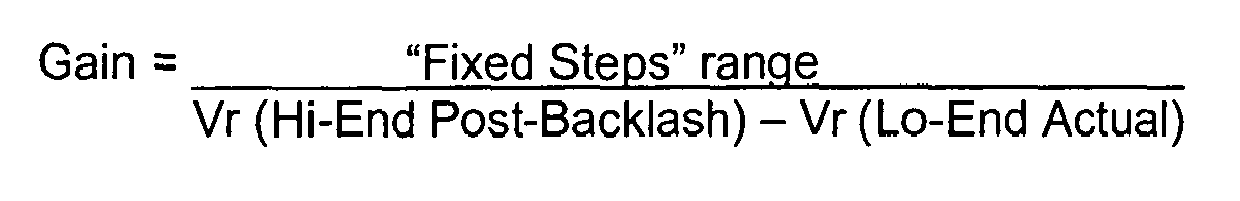
- Using these calculated position values, a "Fixed Steps" range is calculated as:

where 'Gain Limit' is a fixed value derived from manufacturing data supplied with the specific stepper motor and rotary metering valve arrangement for which the gain calculation is being applied. - The fixed steps range is the number of stepper motor steps required to move between the Vr (Hi-End Dem) and Vr (Lo-End Dem) positions, and thus if the valve is moved through this number of steps, the valve can be swept from a fully open to a fully closed position.
- As part of the calibration operation, the valve is moved to the Vr (Hi-End Dem) position, the output of the position sensor being used to determine when this position is reached. Due to the design and manufacturing tolerances associated with the stepper motor and rotary metering valve assembly this Vr (Hi-End Dem) position can fall anywhere between the Vr (Max Flow) and Vr (Hi) positions, as illustrated in
Figure 3 . Also, due to the non-quiescent nature of a stepper motor's discrete angular position behaviour whilst attempting to provide control in an analogue manner, commonly referred to as a motor's operational noise, it is important to lock the stepper motor and rotary metering valve assembly in this Vr (Hi-End Dem) position prior to recording this position for use in the gain calculation. This is achieved by the control unit software commanding zero motor steps movement from the Vr (Hi-End Dem) position and then recording this new commanded position as Vr (Hi-End Pre-Backlash). It is recognised that in terms of actual position, as determined by the output of the position sensor, Vr (Hi-End Dem) and Vr (Hi-End Pre-Backlash) are effectively identical. However, in terms of the control unit software there is a need to provide a distinct difference between the two positions, as illustrated inFigure 3 , to ensure that the aforementioned noise factor is removed from the gain calculation. - It was previously noted that the stepper motor steps represent the positions that the motor will remain fixed at when there is no electrical power applied to the motor. These steps also represent the positions that the motor will move to and remain fixed at when pre-determined electrical currents are applied to the two phases of the dual-phase motor. This is effectively a fixed step power/current, and with the operating current of 500mA the aforementioned zero motor steps movement is commanded by the PCMU applying, for example, 0mA & 500mA to the respective phases of the motor. The PCMU control of the stepper motor is such that for each subsequent step there is a shift in the current applied to each phase of 125mA so that from the zero steps position the sequence of fixed step currents applied to the respective phases will be 125mA & 375mA, 250mA & 250mA, 375mA & 125mA, 500mA & 0mA, etc.
- The motor is then commanded to move through seven, or another predetermined number of, motor steps and the valve position recorded as Vr (Hi-End Post-Backlash). It will be appreciated that, in driving the motor in this manner it can be ensured that the gears of the
gear arrangement 26 are positively engaged. - A value Vr (Lo-End Actual) is then derived by recording the sensor output after having moved the motor by a distance equivalent to the "Fixed Steps" range from the Vr (Hi-End Post-Backlash) position. It will be appreciated that in moving the motor by the "Fixed Steps" range, the valve is moved from the Vr (Hi-End Post-Backlash) position through substantially its full operating range of movement to a fully closed position. After recording the Vr (Lo-End Actual) position sensor output, the gain value can be calculated as:
- The gain value so calculated can then be used in the operating technique described hereinbefore with reference to
Figure 2 . - Although one specific method for calculating the "Gain" value is described hereinbefore, it will be appreciated that other techniques or methods for deriving a value for "Gain" may be used. Indeed, other calibration methods which involve sweeping the valve between fully open and fully closed positions can be used without departing from the scope of the invention, and arrangements maybe possible in which backlash is not specifically accommodated.
- Preferably, the technique used to control the stepper motor and provide finer control, often referred to as granularity, than the aforementioned natural index steps, is one by which the stepper motor position can be controlled to fractions of a stepper motor step, referred to as a micro-stepping method of control. For example the stepper motor position may be controlled to a resolution of one quarter of a natural stepper motor index step. With this micro-stepping method of control, where each micro-step is one quarter of a natural step, the current applied by the PCMU to the phases of the 500mA motor shifts by 31.25mA (1/4 x 125mA) for each micro-step. The PCMU control of the stepper motor at these micro-step positions is even more affected by the aforementioned operational noise. Hence, there is a need not only to provide the zero steps command at start-up as part of the gain calculation, but also to provide monitoring/sampling of the fixed steps movement of the stepper motor wherever possible during its operation. The gear arrangement is conveniently such that, control of the stepper motor to this degree of accuracy equates to controlling the angular position of the valve member to a resolution of 0.08°. However, the invention is not restricted to such an arrangement.
- A number of other modifications and alterations are possible without departing from the scope of the invention.
Claims (14)
- A method of controlling the operation of a metering valve (10) driven by a stepper motor (24), a position sensor (30) normally providing position information to allow control over the metering valve (10) in a closed loop manner, the method comprising the steps of:performing a calibration operation to derive a relationship between stepper motor position and metering valve position;controlling the operation of the metering valve (10) in a closed loop manner; andcontrolling the operation of the metering valve (10) in an open loop manner in the event that the position sensor output is thought to be unreliable; wherein, when operating in the open loop manner, the metering valve (10) is moved to a desired angular position by using the relationship derived in the calibration operation to determine the stepper motor position associated with the desired metering valve position and moving the stepper motor (24) to the determined stepper motor position.
- A method according to Claim 1, wherein the stepper motor position is monitored by counting of the steps through which the stepper motor (24) is moved, in use.
- A method according to Claim 1 or Claim 2, wherein the metering valve (10) is a rotary main metering valve.
- A method according to any of the preceding claims, wherein the position sensor (30) is an RVDT.
- A method according to any of the preceding claims, wherein the stepper motor (24) is a dual-phase stepper motor controlled by the application of appropriate currents to the phases thereof.
- A method according to Claim 5, wherein the stepper motor (24) is controlled using a micro-stepping technique whereby smaller shifts in the applied currents can be used to achieve movement of the motor through fractions of a natural step.
- A method according to any of the preceding claims, wherein the calibration step is performed as part of a power-up procedure.
- A method according to any of the preceding claims, wherein the calibration step involves sweeping the metering valve (10) through its range of normal movement between a fully open position and a fully closed position whilst monitoring the output of the position sensor (30).
- A method according to Claim 8, wherein, as part of the calibration step, a gain value is calculated as a ratio of the movement of the stepper motor (24) to the change in the output of the position sensor (30).
- A method according to Claim 9, wherein the gain value is stored in a non-volatile memory associated with the metering unit of which the metering valve (10) forms part.
- A method according to Claim 9 or Claim 10, wherein the gain value is determined using information relating to the stepper motor positions corresponding to the zero and maximum flow positions of the metering valve (10).
- A method according to Claim 11, wherein the stepper motor positions corresponding to the maximum and minimum hard stop positions of the metering valve (10) are further used in determining the gain value.
- A method according to any of Claims 9 to 12, wherein allowance is made for potential backlash in the drive train between the stepper motor (24) and the metering valve (10).
- A method according to Claim 13, wherein allowance for potential backlash is achieved by driving the metering valve (10) to a known open position, using the position sensor (30) to determine when that position is reached, then driving the
stepper motor (24) to move through a predetermined number of steps, and sensing the position of the metering valve (10) using the position sensor (30).
Applications Claiming Priority (1)
| Application Number | Priority Date | Filing Date | Title |
|---|---|---|---|
| GB0908113A GB0908113D0 (en) | 2009-05-12 | 2009-05-12 | Metering valve control |
Publications (3)
| Publication Number | Publication Date |
|---|---|
| EP2251750A2 true EP2251750A2 (en) | 2010-11-17 |
| EP2251750A3 EP2251750A3 (en) | 2011-02-23 |
| EP2251750B1 EP2251750B1 (en) | 2018-08-15 |
Family
ID=40833843
Family Applications (1)
| Application Number | Title | Priority Date | Filing Date |
|---|---|---|---|
| EP10250824.9A Active EP2251750B1 (en) | 2009-05-12 | 2010-04-24 | Metering valve arrangement |
Country Status (3)
| Country | Link |
|---|---|
| US (1) | US8317156B2 (en) |
| EP (1) | EP2251750B1 (en) |
| GB (1) | GB0908113D0 (en) |
Cited By (1)
| Publication number | Priority date | Publication date | Assignee | Title |
|---|---|---|---|---|
| EP3844439A4 (en) * | 2018-08-27 | 2022-06-15 | Honeywell International Inc. | Improved valve position control |
Families Citing this family (12)
| Publication number | Priority date | Publication date | Assignee | Title |
|---|---|---|---|---|
| JP5601217B2 (en) * | 2011-01-24 | 2014-10-08 | 株式会社デンソー | Expansion valve device |
| US9909533B2 (en) * | 2011-07-29 | 2018-03-06 | Board Of Regents, The University Of Texas System | Pulsed detonation engine |
| US9289350B2 (en) | 2011-09-02 | 2016-03-22 | Electromed, Inc. | Air pulsator control system |
| CN102606786B (en) * | 2012-03-09 | 2013-06-12 | 三一重工股份有限公司 | Electric-hydraulic valve as well as control device and control method thereof |
| US10016335B2 (en) | 2012-03-27 | 2018-07-10 | Electromed, Inc. | Body pulsating apparatus and method |
| EP2943691B1 (en) * | 2012-12-14 | 2021-11-17 | Danfoss Power Solutions II Technology A/S | Online sensor calibration for electrohydraulic valves |
| US9476363B2 (en) * | 2015-01-08 | 2016-10-25 | Solar Turbines Incorporated | Actuator to valve calibration of a fuel control valve assembly |
| US10317099B2 (en) * | 2015-04-16 | 2019-06-11 | Air Distribution Technologies Ip, Llc | Variable air volume diffuser and method of operation |
| JP6540412B2 (en) * | 2015-09-14 | 2019-07-10 | 株式会社島津製作所 | Motor drive mechanism and motor drive method |
| US10626803B2 (en) * | 2015-10-22 | 2020-04-21 | United Technologies Corporation | Apparatus and method for controlling and monitoring an electro-hydraulic servovalve |
| FR3090730B1 (en) * | 2018-12-21 | 2020-12-11 | Safran Aircraft Engines | SYSTEM AND PROCEDURE FOR CONTROL OF A ROTATION SPEED OF AN AIRCRAFT TURBOMACHINE WITH FAILURE MANAGEMENT |
| CN111550592B (en) * | 2019-02-12 | 2022-04-22 | 浙江三花智能控制股份有限公司 | Control method, control system and electric valve |
Family Cites Families (18)
| Publication number | Priority date | Publication date | Assignee | Title |
|---|---|---|---|---|
| US4602653A (en) * | 1984-11-01 | 1986-07-29 | Bear Medical Systems, Inc. | Electronically-controlled gas blending system |
| US4584495A (en) * | 1984-12-17 | 1986-04-22 | Applied Motion Products, Inc. | Performance step motor |
| US5518015A (en) * | 1994-09-30 | 1996-05-21 | Gas Research Institute | Automatic calibrating electrically controlled diaphragm valve actuators and methods for their calibration |
| JP3133233B2 (en) * | 1995-07-06 | 2001-02-05 | 株式会社ユニシアジェックス | Step motor drive control method |
| DE19729101A1 (en) * | 1997-07-08 | 1999-01-14 | Bosch Gmbh Robert | System for operating an internal combustion engine, in particular a motor vehicle |
| US6157888A (en) * | 1999-02-08 | 2000-12-05 | Ford Global Technologies, Inc. | Input smoothing method and apparatus for an electronic throttle control system |
| IT1314504B1 (en) * | 2000-03-02 | 2002-12-18 | Cozzani Mario S R L | VALVE FOR THE CONTROL OF LARGE SECTION FLOWS, IN PARTICULAR FOR COMPRESSORS OR SIMILAR. |
| DE10124847A1 (en) * | 2001-05-22 | 2002-11-28 | Abb Patent Gmbh | Operating actuator drive e.g. for pipeline, involves maximum actuation speed during first phase, and reducing actuation speed continuously with defined gradient from predefined position in second phase |
| US6597077B2 (en) * | 2001-11-29 | 2003-07-22 | Ted T. Lin | Stator coil T-connection for two-phase step motors |
| NZ533922A (en) * | 2001-12-04 | 2008-12-24 | Truckgas Pty Ltd | Fuel control system for mixture of fuels to combustion engine |
| US7312595B2 (en) * | 2002-07-09 | 2007-12-25 | Denso Corporation | Motor control apparatus |
| GB0317394D0 (en) * | 2003-07-25 | 2003-08-27 | Goodrich Control Sys Ltd | Engine fuel control |
| US6957801B2 (en) * | 2003-09-30 | 2005-10-25 | Honeywell International, Inc. | Valve having an integrated actuator assembly |
| US7963185B2 (en) * | 2005-09-23 | 2011-06-21 | Woodward, Inc. | Stepper motor driven proportional actuator |
| US7640078B2 (en) * | 2006-07-05 | 2009-12-29 | Advanced Energy Industries, Inc. | Multi-mode control algorithm |
| GB0618356D0 (en) * | 2006-09-19 | 2006-10-25 | Goodrich Control Sys Ltd | Rotary metering valve arrangement |
| US7656115B2 (en) * | 2007-06-15 | 2010-02-02 | Trane International Inc. | Calibrating stepper motor by driving fractional ranges |
| US20090277519A1 (en) * | 2008-05-06 | 2009-11-12 | Hr Textron, Inc. | Method and apparatus for controlling fluid flow rate characteristics of a valve assembly |
-
2009
- 2009-05-12 GB GB0908113A patent/GB0908113D0/en not_active Ceased
-
2010
- 2010-04-24 EP EP10250824.9A patent/EP2251750B1/en active Active
- 2010-04-27 US US12/768,197 patent/US8317156B2/en active Active
Non-Patent Citations (1)
| Title |
|---|
| None |
Cited By (1)
| Publication number | Priority date | Publication date | Assignee | Title |
|---|---|---|---|---|
| EP3844439A4 (en) * | 2018-08-27 | 2022-06-15 | Honeywell International Inc. | Improved valve position control |
Also Published As
| Publication number | Publication date |
|---|---|
| GB0908113D0 (en) | 2009-06-24 |
| EP2251750A3 (en) | 2011-02-23 |
| US20100288364A1 (en) | 2010-11-18 |
| EP2251750B1 (en) | 2018-08-15 |
| US8317156B2 (en) | 2012-11-27 |
Similar Documents
| Publication | Publication Date | Title |
|---|---|---|
| EP2251750B1 (en) | Metering valve arrangement | |
| EP2492473B1 (en) | Fuel system | |
| RU2534647C2 (en) | Valve drive | |
| EP3228847B1 (en) | System and method for an adaptive fuel flow estimation with flow meter feedback | |
| US7762080B2 (en) | Fuel metering pump calibration method | |
| US11162433B2 (en) | Method of controlling gas generator power and torque output | |
| EP4035998B1 (en) | System and method for detecting failure of a propeller feedback device | |
| EP2985439B1 (en) | Distributed fuel control system | |
| WO2015053930A1 (en) | Method and apparatus for controlling a turboprop engine | |
| DE102007017256A1 (en) | A fuel supply device for a motor and control method therefor | |
| US20070044768A1 (en) | Enhanced accuracy fuel metering system and method | |
| US5168447A (en) | Engine trim control unit | |
| US20110190966A1 (en) | Control System For An Aircraft Propeller Drive | |
| EP2021602A1 (en) | Modular fuel supply device for a gas turbine | |
| EP3244040B1 (en) | Multivariable fuel control and estimator (mfce) for preventing combustor blowout | |
| CN113135284A (en) | Propeller blade pitch angle feedback generated by actuator rotation | |
| EP2639157B1 (en) | Cabin pressure control system with multiple outflow valves and method of calibrating the outflow valve position feedback during flight | |
| EP1872003B1 (en) | Stepper motor driven proportional fuel metering valve | |
| RU2631974C2 (en) | Gas-turbine engine with augmented combustion chamber operation mode and its actualization system | |
| EP1894072B1 (en) | Method of actuator control | |
| US12448924B2 (en) | Aircraft hybrid duplex-triplex control architecture | |
| KR101782228B1 (en) | Intake System of Vehicle and Method of Driving Thereof | |
| RU2855586C1 (en) | Fault-tolerant electronic digital automatic control system of aircraft gas turbine engine with backup hydromechanical single-regime control | |
| KR20090055748A (en) | Actuator structure of engine and its control method |
Legal Events
| Date | Code | Title | Description |
|---|---|---|---|
| PUAI | Public reference made under article 153(3) epc to a published international application that has entered the european phase |
Free format text: ORIGINAL CODE: 0009012 |
|
| AK | Designated contracting states |
Kind code of ref document: A2 Designated state(s): AT BE BG CH CY CZ DE DK EE ES FI FR GB GR HR HU IE IS IT LI LT LU LV MC MK MT NL NO PL PT RO SE SI SK SM TR |
|
| AX | Request for extension of the european patent |
Extension state: AL BA ME RS |
|
| PUAL | Search report despatched |
Free format text: ORIGINAL CODE: 0009013 |
|
| AK | Designated contracting states |
Kind code of ref document: A3 Designated state(s): AT BE BG CH CY CZ DE DK EE ES FI FR GB GR HR HU IE IS IT LI LT LU LV MC MK MT NL NO PL PT RO SE SI SK SM TR |
|
| AX | Request for extension of the european patent |
Extension state: AL BA ME RS |
|
| 17P | Request for examination filed |
Effective date: 20110718 |
|
| 17Q | First examination report despatched |
Effective date: 20150213 |
|
| GRAP | Despatch of communication of intention to grant a patent |
Free format text: ORIGINAL CODE: EPIDOSNIGR1 |
|
| STAA | Information on the status of an ep patent application or granted ep patent |
Free format text: STATUS: GRANT OF PATENT IS INTENDED |
|
| RIC1 | Information provided on ipc code assigned before grant |
Ipc: G05B 9/02 20060101AFI20180131BHEP Ipc: F16K 37/00 20060101ALI20180131BHEP Ipc: G05B 7/02 20060101ALI20180131BHEP Ipc: F02C 9/26 20060101ALI20180131BHEP Ipc: F16K 3/06 20060101ALI20180131BHEP |
|
| INTG | Intention to grant announced |
Effective date: 20180302 |
|
| GRAS | Grant fee paid |
Free format text: ORIGINAL CODE: EPIDOSNIGR3 |
|
| GRAA | (expected) grant |
Free format text: ORIGINAL CODE: 0009210 |
|
| STAA | Information on the status of an ep patent application or granted ep patent |
Free format text: STATUS: THE PATENT HAS BEEN GRANTED |
|
| AK | Designated contracting states |
Kind code of ref document: B1 Designated state(s): AT BE BG CH CY CZ DE DK EE ES FI FR GB GR HR HU IE IS IT LI LT LU LV MC MK MT NL NO PL PT RO SE SI SK SM TR |
|
| REG | Reference to a national code |
Ref country code: CH Ref legal event code: EP Ref country code: GB Ref legal event code: FG4D Ref country code: AT Ref legal event code: REF Ref document number: 1030479 Country of ref document: AT Kind code of ref document: T Effective date: 20180815 |
|
| REG | Reference to a national code |
Ref country code: IE Ref legal event code: FG4D |
|
| REG | Reference to a national code |
Ref country code: DE Ref legal event code: R096 Ref document number: 602010052717 Country of ref document: DE |
|
| REG | Reference to a national code |
Ref country code: NL Ref legal event code: MP Effective date: 20180815 |
|
| REG | Reference to a national code |
Ref country code: LT Ref legal event code: MG4D |
|
| REG | Reference to a national code |
Ref country code: AT Ref legal event code: MK05 Ref document number: 1030479 Country of ref document: AT Kind code of ref document: T Effective date: 20180815 |
|
| PG25 | Lapsed in a contracting state [announced via postgrant information from national office to epo] |
Ref country code: FI Free format text: LAPSE BECAUSE OF FAILURE TO SUBMIT A TRANSLATION OF THE DESCRIPTION OR TO PAY THE FEE WITHIN THE PRESCRIBED TIME-LIMIT Effective date: 20180815 Ref country code: AT Free format text: LAPSE BECAUSE OF FAILURE TO SUBMIT A TRANSLATION OF THE DESCRIPTION OR TO PAY THE FEE WITHIN THE PRESCRIBED TIME-LIMIT Effective date: 20180815 Ref country code: IS Free format text: LAPSE BECAUSE OF FAILURE TO SUBMIT A TRANSLATION OF THE DESCRIPTION OR TO PAY THE FEE WITHIN THE PRESCRIBED TIME-LIMIT Effective date: 20181215 Ref country code: NO Free format text: LAPSE BECAUSE OF FAILURE TO SUBMIT A TRANSLATION OF THE DESCRIPTION OR TO PAY THE FEE WITHIN THE PRESCRIBED TIME-LIMIT Effective date: 20181115 Ref country code: SE Free format text: LAPSE BECAUSE OF FAILURE TO SUBMIT A TRANSLATION OF THE DESCRIPTION OR TO PAY THE FEE WITHIN THE PRESCRIBED TIME-LIMIT Effective date: 20180815 Ref country code: GR Free format text: LAPSE BECAUSE OF FAILURE TO SUBMIT A TRANSLATION OF THE DESCRIPTION OR TO PAY THE FEE WITHIN THE PRESCRIBED TIME-LIMIT Effective date: 20181116 Ref country code: BG Free format text: LAPSE BECAUSE OF FAILURE TO SUBMIT A TRANSLATION OF THE DESCRIPTION OR TO PAY THE FEE WITHIN THE PRESCRIBED TIME-LIMIT Effective date: 20181115 Ref country code: NL Free format text: LAPSE BECAUSE OF FAILURE TO SUBMIT A TRANSLATION OF THE DESCRIPTION OR TO PAY THE FEE WITHIN THE PRESCRIBED TIME-LIMIT Effective date: 20180815 Ref country code: LT Free format text: LAPSE BECAUSE OF FAILURE TO SUBMIT A TRANSLATION OF THE DESCRIPTION OR TO PAY THE FEE WITHIN THE PRESCRIBED TIME-LIMIT Effective date: 20180815 |
|
| PG25 | Lapsed in a contracting state [announced via postgrant information from national office to epo] |
Ref country code: LV Free format text: LAPSE BECAUSE OF FAILURE TO SUBMIT A TRANSLATION OF THE DESCRIPTION OR TO PAY THE FEE WITHIN THE PRESCRIBED TIME-LIMIT Effective date: 20180815 Ref country code: HR Free format text: LAPSE BECAUSE OF FAILURE TO SUBMIT A TRANSLATION OF THE DESCRIPTION OR TO PAY THE FEE WITHIN THE PRESCRIBED TIME-LIMIT Effective date: 20180815 Ref country code: ES Free format text: LAPSE BECAUSE OF FAILURE TO SUBMIT A TRANSLATION OF THE DESCRIPTION OR TO PAY THE FEE WITHIN THE PRESCRIBED TIME-LIMIT Effective date: 20180815 |
|
| PG25 | Lapsed in a contracting state [announced via postgrant information from national office to epo] |
Ref country code: PL Free format text: LAPSE BECAUSE OF FAILURE TO SUBMIT A TRANSLATION OF THE DESCRIPTION OR TO PAY THE FEE WITHIN THE PRESCRIBED TIME-LIMIT Effective date: 20180815 Ref country code: CZ Free format text: LAPSE BECAUSE OF FAILURE TO SUBMIT A TRANSLATION OF THE DESCRIPTION OR TO PAY THE FEE WITHIN THE PRESCRIBED TIME-LIMIT Effective date: 20180815 Ref country code: RO Free format text: LAPSE BECAUSE OF FAILURE TO SUBMIT A TRANSLATION OF THE DESCRIPTION OR TO PAY THE FEE WITHIN THE PRESCRIBED TIME-LIMIT Effective date: 20180815 Ref country code: EE Free format text: LAPSE BECAUSE OF FAILURE TO SUBMIT A TRANSLATION OF THE DESCRIPTION OR TO PAY THE FEE WITHIN THE PRESCRIBED TIME-LIMIT Effective date: 20180815 |
|
| REG | Reference to a national code |
Ref country code: DE Ref legal event code: R097 Ref document number: 602010052717 Country of ref document: DE |
|
| PG25 | Lapsed in a contracting state [announced via postgrant information from national office to epo] |
Ref country code: DK Free format text: LAPSE BECAUSE OF FAILURE TO SUBMIT A TRANSLATION OF THE DESCRIPTION OR TO PAY THE FEE WITHIN THE PRESCRIBED TIME-LIMIT Effective date: 20180815 Ref country code: SM Free format text: LAPSE BECAUSE OF FAILURE TO SUBMIT A TRANSLATION OF THE DESCRIPTION OR TO PAY THE FEE WITHIN THE PRESCRIBED TIME-LIMIT Effective date: 20180815 Ref country code: SK Free format text: LAPSE BECAUSE OF FAILURE TO SUBMIT A TRANSLATION OF THE DESCRIPTION OR TO PAY THE FEE WITHIN THE PRESCRIBED TIME-LIMIT Effective date: 20180815 |
|
| PLBE | No opposition filed within time limit |
Free format text: ORIGINAL CODE: 0009261 |
|
| STAA | Information on the status of an ep patent application or granted ep patent |
Free format text: STATUS: NO OPPOSITION FILED WITHIN TIME LIMIT |
|
| 26N | No opposition filed |
Effective date: 20190516 |
|
| PG25 | Lapsed in a contracting state [announced via postgrant information from national office to epo] |
Ref country code: SI Free format text: LAPSE BECAUSE OF FAILURE TO SUBMIT A TRANSLATION OF THE DESCRIPTION OR TO PAY THE FEE WITHIN THE PRESCRIBED TIME-LIMIT Effective date: 20180815 |
|
| REG | Reference to a national code |
Ref country code: CH Ref legal event code: PL |
|
| REG | Reference to a national code |
Ref country code: BE Ref legal event code: MM Effective date: 20190430 |
|
| PG25 | Lapsed in a contracting state [announced via postgrant information from national office to epo] |
Ref country code: MC Free format text: LAPSE BECAUSE OF FAILURE TO SUBMIT A TRANSLATION OF THE DESCRIPTION OR TO PAY THE FEE WITHIN THE PRESCRIBED TIME-LIMIT Effective date: 20180815 Ref country code: LU Free format text: LAPSE BECAUSE OF NON-PAYMENT OF DUE FEES Effective date: 20190424 |
|
| PG25 | Lapsed in a contracting state [announced via postgrant information from national office to epo] |
Ref country code: LI Free format text: LAPSE BECAUSE OF NON-PAYMENT OF DUE FEES Effective date: 20190430 Ref country code: CH Free format text: LAPSE BECAUSE OF NON-PAYMENT OF DUE FEES Effective date: 20190430 |
|
| PG25 | Lapsed in a contracting state [announced via postgrant information from national office to epo] |
Ref country code: BE Free format text: LAPSE BECAUSE OF NON-PAYMENT OF DUE FEES Effective date: 20190430 |
|
| PG25 | Lapsed in a contracting state [announced via postgrant information from national office to epo] |
Ref country code: TR Free format text: LAPSE BECAUSE OF FAILURE TO SUBMIT A TRANSLATION OF THE DESCRIPTION OR TO PAY THE FEE WITHIN THE PRESCRIBED TIME-LIMIT Effective date: 20180815 |
|
| PG25 | Lapsed in a contracting state [announced via postgrant information from national office to epo] |
Ref country code: IE Free format text: LAPSE BECAUSE OF NON-PAYMENT OF DUE FEES Effective date: 20190424 |
|
| PG25 | Lapsed in a contracting state [announced via postgrant information from national office to epo] |
Ref country code: PT Free format text: LAPSE BECAUSE OF FAILURE TO SUBMIT A TRANSLATION OF THE DESCRIPTION OR TO PAY THE FEE WITHIN THE PRESCRIBED TIME-LIMIT Effective date: 20181215 |
|
| PG25 | Lapsed in a contracting state [announced via postgrant information from national office to epo] |
Ref country code: CY Free format text: LAPSE BECAUSE OF FAILURE TO SUBMIT A TRANSLATION OF THE DESCRIPTION OR TO PAY THE FEE WITHIN THE PRESCRIBED TIME-LIMIT Effective date: 20180815 |
|
| PG25 | Lapsed in a contracting state [announced via postgrant information from national office to epo] |
Ref country code: MT Free format text: LAPSE BECAUSE OF FAILURE TO SUBMIT A TRANSLATION OF THE DESCRIPTION OR TO PAY THE FEE WITHIN THE PRESCRIBED TIME-LIMIT Effective date: 20180815 Ref country code: HU Free format text: LAPSE BECAUSE OF FAILURE TO SUBMIT A TRANSLATION OF THE DESCRIPTION OR TO PAY THE FEE WITHIN THE PRESCRIBED TIME-LIMIT; INVALID AB INITIO Effective date: 20100424 |
|
| PG25 | Lapsed in a contracting state [announced via postgrant information from national office to epo] |
Ref country code: MK Free format text: LAPSE BECAUSE OF FAILURE TO SUBMIT A TRANSLATION OF THE DESCRIPTION OR TO PAY THE FEE WITHIN THE PRESCRIBED TIME-LIMIT Effective date: 20180815 |
|
| PGFP | Annual fee paid to national office [announced via postgrant information from national office to epo] |
Ref country code: DE Payment date: 20250319 Year of fee payment: 16 |
|
| PGFP | Annual fee paid to national office [announced via postgrant information from national office to epo] |
Ref country code: GB Payment date: 20260319 Year of fee payment: 17 |
|
| PGFP | Annual fee paid to national office [announced via postgrant information from national office to epo] |
Ref country code: IT Payment date: 20260319 Year of fee payment: 17 |
|
| PGFP | Annual fee paid to national office [announced via postgrant information from national office to epo] |
Ref country code: FR Payment date: 20260319 Year of fee payment: 17 |