EP2250967A1 - Tomography apparatus and tomography method - Google Patents
Tomography apparatus and tomography method Download PDFInfo
- Publication number
- EP2250967A1 EP2250967A1 EP09006483A EP09006483A EP2250967A1 EP 2250967 A1 EP2250967 A1 EP 2250967A1 EP 09006483 A EP09006483 A EP 09006483A EP 09006483 A EP09006483 A EP 09006483A EP 2250967 A1 EP2250967 A1 EP 2250967A1
- Authority
- EP
- European Patent Office
- Prior art keywords
- radiation
- mask
- detector
- radiation beam
- ring
- Prior art date
- Legal status (The legal status is an assumption and is not a legal conclusion. Google has not performed a legal analysis and makes no representation as to the accuracy of the status listed.)
- Withdrawn
Links
Images



Classifications
-
- G—PHYSICS
- G21—NUCLEAR PHYSICS; NUCLEAR ENGINEERING
- G21K—HANDLING OF PARTICLES OR IONISING RADIATION NOT OTHERWISE PROVIDED FOR; IRRADIATION DEVICES; GAMMA RAY OR X-RAY MICROSCOPES
- G21K1/00—Arrangements for handling particles or ionising radiation, e.g. focusing or moderating
- G21K1/02—Arrangements for handling particles or ionising radiation, e.g. focusing or moderating using diaphragms, collimators
- G21K1/025—Arrangements for handling particles or ionising radiation, e.g. focusing or moderating using diaphragms, collimators using multiple collimators, e.g. Bucky screens; other devices for eliminating undesired or dispersed radiation
-
- A—HUMAN NECESSITIES
- A61—MEDICAL OR VETERINARY SCIENCE; HYGIENE
- A61B—DIAGNOSIS; SURGERY; IDENTIFICATION
- A61B6/00—Apparatus or devices for radiation diagnosis; Apparatus or devices for radiation diagnosis combined with radiation therapy equipment
- A61B6/02—Arrangements for diagnosis sequentially in different planes; Stereoscopic radiation diagnosis
- A61B6/03—Computed tomography [CT]
- A61B6/032—Transmission computed tomography [CT]
-
- A—HUMAN NECESSITIES
- A61—MEDICAL OR VETERINARY SCIENCE; HYGIENE
- A61B—DIAGNOSIS; SURGERY; IDENTIFICATION
- A61B6/00—Apparatus or devices for radiation diagnosis; Apparatus or devices for radiation diagnosis combined with radiation therapy equipment
- A61B6/06—Diaphragms
-
- A—HUMAN NECESSITIES
- A61—MEDICAL OR VETERINARY SCIENCE; HYGIENE
- A61B—DIAGNOSIS; SURGERY; IDENTIFICATION
- A61B6/00—Apparatus or devices for radiation diagnosis; Apparatus or devices for radiation diagnosis combined with radiation therapy equipment
- A61B6/40—Arrangements for generating radiation specially adapted for radiation diagnosis
- A61B6/4021—Arrangements for generating radiation specially adapted for radiation diagnosis involving movement of the focal spot
- A61B6/4028—Arrangements for generating radiation specially adapted for radiation diagnosis involving movement of the focal spot resulting in acquisition of views from substantially different positions, e.g. EBCT
-
- A—HUMAN NECESSITIES
- A61—MEDICAL OR VETERINARY SCIENCE; HYGIENE
- A61B—DIAGNOSIS; SURGERY; IDENTIFICATION
- A61B6/00—Apparatus or devices for radiation diagnosis; Apparatus or devices for radiation diagnosis combined with radiation therapy equipment
- A61B6/54—Control of apparatus or devices for radiation diagnosis
- A61B6/542—Control of apparatus or devices for radiation diagnosis involving control of exposure
Definitions
- the invention relates to a tomography apparatus and a tomography method for generating images of an object, e.g. a patient.
- the novel tomography apparatus for generating images of an object comprises a radiation source (e.g. an X-ray source) emitting a radiation beam, wherein the radiation beam rotates around the object and penetrates the object.
- a radiation source e.g. an X-ray source
- the tomography apparatus generates sectional two-dimensional images of the object in a specific measurement plane.
- the radiation beam can be restricted to the measurement plane.
- the radiation beam can be fan-shaped and aligned coplanar with the measurement plane.
- the tomography apparatus generates three-dimensional images.
- the radiation beam extends axially with regard to the rotary axis of the radiation beam, so that the radation beam penetrates the object not only in a single measurement plane but over the entire length or at least a portion of the object. This can be advantageous since the entire volume of the object can be scanned during a single rotation of the radiation beam.
- the novel tomography apparatus comprises a radiation detector rotating around the object opposite the radiation source, so that the radiation detector detects the radiation beam after penetration of the object.
- the novel tomography apparatus comprises a radiation mask for masking the radiation beam, wherein the radiation mask is arranged in the path of the radiation beam between the radiation source and the radiation detector.
- the novel tomography apparatus is characterized in that the radiation beam passes the radiation mask only once between the radiation source and the radiation detector so that the radiation dose applied during scanning can be reduced.
- the radiation mask is ring-shaped and surrounds the object.
- the radiation detector is arranged inside the ring-shaped radiation mask so that the radiation beam passes the radiation mask only once on its path from the radiation source to the radiation detector thereby allowing a reduction of the radiation doses applied during scanning.
- the radiation mask is also ring-shaped and surrounds the object.
- the second embodiment of the invention provides that the radiation detector is arranged outside the ring-shaped radiation mask as disclosed, for example, in the afore-mentioned patent publication WO 2007/048590 A1 . Therefore, the mask plane (i.e. the midplane or centre plane of the mask) is tilted relative to the measurement plane, wherein the mask plane intersects the measurement plane, so that the radiation beam passes the radiation mask only once on its path between the radiation source and the radiation detector.
- the ring-shaped radiation mask is tilted relative to the measurement plane in such a way that one side of the radiation mask is in the measurement plane and therefore affects the radiation beam while the opposing side of the radiation mask is tilted out of the measurement plane and therefore does not affect the radiation beam.
- the radiation mask preferably performs a precession movement around an axis perpendicular to the measurement plane, so that a surface normal of the mask plane is always facing the radiation source.
- a fixed angular position of the radiation mask relative to the radiation beam is maintained while the radiation beam is rotating around the object (e.g. a patient) during scanning. Therefore, the afore-mentioned precession movement of the radiation mask is preferably synchronized with the rotation of the radiation beam.
- the mask plane and the measurement plane include a predetermined tilt angle, wherein the tilt angle can be greater than 2°, 5°, 7° or 10° and/or smaller than 60°, 45°, 30° or even smaller than 25°.
- the invention is not restricted to the afore-mentioned exemplary values of the tilt angle.
- the radiation mask is also ring-shaped and arranged around the object, wherein the radiation detector is arranged outside the ring-shaped radiation mask.
- the radiation mask comprises several adjacent sectors which are distributed around the object along the circumference of the ring-shaped radiation mask. The individual sectors of the radiation mask can be moved selectively into the path of the radiation beam or out of the path of the radiation beam so that the radiation beam passes the radiation mask only once on its path between the radiation source and the radiation detector.
- the sectors of the radiation mask are moved into the path of the radiation beam, while the sectors on the opposing side of the radiation mask are moved out of the radiation beam so that the radiation beam penetrates only one sector of the radiation mask thereby allowing a reduction of the radiation doses applied during scanning.
- the sectors of the radiation mask are preferably moveable orthogonally to the mask plane or parallel to the rotary axis of the radiation beam.
- the radiation mask preferably comprises N shielding elements which are separated by radiation windows wherein the shielding elements are arranged around the object. Further, the radiation mask preferably comprises n selectively moveable sectors each extending over an angle of 360°/n around the object. Moreover, there is preferably a specific relationship 3 ⁇ n ⁇ N between the number N of shielding elements and the number n of the moveable sectors of the radiation mask.
- the radiation mask is only partially ring-shaped and open on one side thereby avoiding a second collimation of the radiation beam on its path to the radiation detector.
- the radiation mask covers a predetermined angle around the object, wherein the angle of coverage is preferably in the range of 180°-270°.
- the radiation mask is preferably partially ring-shaped and surrounds the object.
- the sector-shaped opening in the radiation mask allows an arrangement of the radiation detector outside the ring-shaped radiation mask.
- the radiation mask is preferably discretely moved around the object at predetermined angular steps ⁇ and the radiation mask preferably comprises N shielding elements which are separated by radiation windows, wherein the shielding elements are angularly arranged around the object.
- the invention comprises a fifth embodiment in which the radiation source comprises a ring-shaped anode surrounding the object, preferably in the measurement plane.
- the radiation source comprises an electron source directing the electron beam onto the ring-shaped anode surrounding the object thereby generating the radiation beam as a secondary X-radiation beam.
- the ring-shaped anode comprises several anode elements which are spaced apart and distributed around the object so that the anode constitutes the radiation mask. Further, the electron beam is moved around the ring-shaped anode along the circumference of the ring-shaped anode, so that the secondary X-radiation beam rotates around the object.
- the radiation detector preferably rotates around the object, wherein the electron beam and the radiation detector are moved in the same direction and with the same angular speed around the object so that the radiation detector and the target point of the electron beam on the ring-shaped anode are always on opposite sides of the object, so that the secondary X-radiation beam penetrates the object on its path to the radiation detector.
- the electron beam is preferably aligned substantially parallel or acute-angled to the surface normal of the measurement plane.
- the electron beam preferably rotates on the surface shell of a cone wherein the circumference of the ground area of the cone is constituted by the ring-shaped anode.
- the radiation detector can be flat or curved in the measurement plane.
- the radiation detector is arranged inside the ring-shaped radiation mask and preferably extends up to the size that is enough to cover the radiation after penetration of the object surrounded by the radiation mask.
- the radiation mask can be arranged fixedly, which is preferred in the afore-mentioned first embodiment of the invention.
- the radiation beam is preferably fan-shaped and substantially co-planar with the measurement plane so that the fan-shaped radiation beam penetrates the entire section of the object in the measurement plane.
- the radiation beam is cone-shaped and in this case the central fan of the cone beam is co-planar with the central plane of the ring.
- the radiation detector is preferably radiation-sensitive along a predetermined extension along the measurement plane and/or along the rotary axis of the radiation beam. This contrasts to a radiation detector comprising a point-shaped sensitivity.
- the radiation beam penetrating the object is preferably an X-radiation beam.
- the invention is not restricted to X-radiation.
- the radiation mask is preferably made of a material which is radiation absorbing, particularly lead or tungsten.
- the radiation source and the radiation detector are preferably arranged on a gantry on opposite sides of the object, wherein the gantry rotates in the measurement plane.
- the radiation beam, the radiation source and the radiation detector preferably carry out coaxial rotary motions.
- the radiation detector preferably rotates in the same direction and at the same angular speed around the object as the radiation beam.
- the radiation source can be arranged fixedly while the secondary radiation beam rotates around the object.
- the radiation source itself rotates around the object.
- the invention preferably relates to a computer tomography apparatus of the third generation, i.e. a rotate/rotate device comprising both a rotating radiation source and a rotating radiation detector.
- the invention is not restricted to a tomography apparatus of the third generation.
- Figure 1 shows a sectional view of a computer tomography apparatus 1 of the so-called third generation, i.e. the computer tomography apparatus 1 comprises a rotating radiation source 2 and a rotating radiation detector 3.
- the computer tomography apparatus 1 can be used for generating sectional images of an object 4 (e.g. a patient) in a measurement plane which is identical with the cutting plane shown in the drawing.
- an object 4 e.g. a patient
- a measurement plane which is identical with the cutting plane shown in the drawing.
- the radiation source 2 rotates around the object 4 on a circular path 5 in the direction of the arrow, i.e. counter-clockwise.
- the radiation detector 3 rotates around the object 4 in the direction of the arrow counter-clockwise, wherein the rotation of the radiation source 2 and the rotation of the radiation detector 3 are synchronized so that the radiation source 2 and the radiation detector 3 are always on opposite sides of the object 4.
- the radiation source 2 emits a fan-shaped radiation beam 6 which is coplanar with the measurement plane, wherein the fan angle of the radiation beam 6 is sufficiently large that the fan-shaped radiation beam 6 covers the entire lateral extension of the object 4 in the measurement plane.
- the computer tomography apparatus 1 comprises a ring-shaped radiation mask 7 surrounding the object 4, wherein the radiation mask 7 is arranged coaxially to the circular path 5 of the radiation source 2.
- the radiation mask 7 consists of a large number of shielding elements which are arranged along the circumference of the ring-shaped radiation mask 7, so that the individual shielding elements of the radiation mask are separated by radiation windows which can be penetrated by the radiation beam 6.
- the shielding elements of the radiation mask 7 consist of a material with high radiation absorption properties like lead (Pb) or tungsten (W).
- the shielding elements alternate with radiation windows of the same size.
- the novel computer tomography apparatus 1 differs from conventional computer tomography apparatuses in that the radiation source is outside of the ring-shaped mask and the radiation detector 3 is arranged inside the ring-shaped radiation mask 7, so that the radiation beam 6 passes the radiation mask 7 only once on its path between the radiation source 2 and the radiation detector 3. This is advantageous since it allows a significant reduction of the radiation doses applied during scanning of the object 4.
- the radiation detector 3 is flat and extends laterally up to the inside of the radiation mask 7.
- FIG 2 shows a modification of the first embodiment of the invention as shown in Figure 1 , so that reference is made to the above description and the same reference numerals are used for corresponding parts and details.
- the radiation detector 3 is not flat but curved.
- FIGS 3A and 3B illustrate the afore-mentioned second embodiment of the invention, which is similar to the afore-mentioned first embodiment of the invention, so that reference is made to the above description and the same reference numerals are used for corresponding parts and details.
- the radiation detector 3 is arranged outside the ring-shaped radiation mask 7.
- the radiation mask 7 is arranged in a mask plane 8 which is tilted relative to the measurement plane 9 by a tilt angle ⁇ ⁇ 20° so that the radiation beam 6 passes the radiation mask 7 on one side only, i.e. between the radiation source 2 and the object 4, while the other side of the radiation mask 7 is tilted out of the measurement plane 9 and therefore does not affect the radiation beam 6.
- the radiation mask 7 carries out a precession movement around a centre axis 10, so that a surface normal 11 of the radiation mask 7 always faces the radiation source 2.
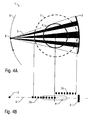
- FIGS 4A and 4B illustrate the afore-mentioned third embodiment of the invention, which is similar to the other embodiments of the invention so that reference is made to the above description and the same reference numerals are used for corresponding parts and details.
- the radiation mask 7 consists of several sectors 7A, 7B which can be moved selectively into the measurement plane 9 or out of the measurement plane 9.
- the sector 7A is moved into the measurement plane 9 while the opposing sector 7B is moved out of the measurement plane 9. Therefore, the sector 7A of the radiation mask 7 affects the radiation beam 6 while the opposing sector 7B of the radiation mask 7 does not affect the radiation beam 6 since it is moved out of the measurement plane 9.
- the movement of the sectors 7A, 7B of the radiation mask 7 is controlled in such a way that the radiation beam 6 passes only one of the opposing sectors 7A, 7B of the radiation mask 7.
- FIGS 5A and 5B illustrate the afore-mentioned fourth embodiment of the invention which is partially similar to the other embodiments so that reference is made to the above description and the same reference numerals are used for corresponding parts and details.
- the radiation mask 7 is partially ring-shaped but open on one side. Therefore, the radiation beam 6 passes the radiation mask 7 only once on its path between the radiation source 2 and the radiation detector 3.
- Figure 6 illustrates the afore-mentioned fifth embodiment of the invention which is partially similar to the other embodiments so that reference is made to the above description and the same reference numerals are used for corresponding parts and details.
- the radiation mask 7 consists of a ring-shaped anode which is hit by an electron beam 12 which is generated by the radiation source 2.
- the target point 13 of the electron beam on the ring-shaped anode generates secondary X-radiation which penetrates the object 4.
- the electron beam 12 is moved on the surface shell of a cone surrounding the centre axis 10 so that the target point 13 of the electron beam 12 on the ring-shaped anode rotates around the object along the circumference of the ring-shaped radiation mask 7.
- Figure 7 illustrates the sixth embodiment of the invention which is partially similar to the other embodiments so that reference is made to the above description and the same reference numerals are used for corresponding parts and details.
- the radiation beam 6 is not restricted to a single measurement plane. Instead, the radiation beam 6 has an axial extension with regard to the central axis 10 which is the rotary axis of the radiation beam 6.
- the radiation mask 7 is not restricted to a single measurement plane. Instead, the radiation mask 7 has an axial extension along the central axis 10 so that it masks the entire radiation beam 6 along its axial extension.
- the radiation detector 3 has an axial extension along the central axis 10.
- the tomography apparatus 1 of this embodiment generates three-dimensional images of the object 4 (e.g. a patient) in contrast to the afore-mentioned other embodiments of the invention which merely generate sectional images of the object.
Landscapes
- Health & Medical Sciences (AREA)
- Life Sciences & Earth Sciences (AREA)
- Engineering & Computer Science (AREA)
- Medical Informatics (AREA)
- Physics & Mathematics (AREA)
- High Energy & Nuclear Physics (AREA)
- Heart & Thoracic Surgery (AREA)
- Animal Behavior & Ethology (AREA)
- Optics & Photonics (AREA)
- Pathology (AREA)
- Radiology & Medical Imaging (AREA)
- Biomedical Technology (AREA)
- Biophysics (AREA)
- Molecular Biology (AREA)
- Surgery (AREA)
- Nuclear Medicine, Radiotherapy & Molecular Imaging (AREA)
- General Health & Medical Sciences (AREA)
- Public Health (AREA)
- Veterinary Medicine (AREA)
- Pulmonology (AREA)
- Theoretical Computer Science (AREA)
- Spectroscopy & Molecular Physics (AREA)
- General Engineering & Computer Science (AREA)
- Apparatus For Radiation Diagnosis (AREA)
- Analysing Materials By The Use Of Radiation (AREA)
Abstract
The invention relates to a tomography apparatus (1) for generating sectional images of an object (4) in a measurement plane, comprising: a radiation source (2) emitting a radiation beam (6), wherein the radiation beam (6) rotates in the measurement plane relative to the object (4) and penetrates the object (4); a radiation detector (3) rotating around the object (4) in the measurement plane opposite the radiation source (2), so that the radiation detector (3) detects the radiation beam (6) after penetration of the object (4); a radiation mask (7) for masking the radiation beam (6), wherein the radiation mask (7) is arranged in the path of the radiation beam (6) between the radiation source (2) and the radiation detector (3). The inventors propose an arrangement in which the radiation beam (6) passes the radiation mask (7) only once between the radiation source (2) and the radiation detector (3).
Description
- The invention relates to a tomography apparatus and a tomography method for generating images of an object, e.g. a patient.
- Conventional computer tomography apparatuses of the third generation are disclosed, for example, in
WO 2007/048590 A1 . One problem associated with these conventional computer tomography apparatuses is that high doses of radiation are applied to the patient during scanning. - Therefore, it is a general object of the invention to reduce the radiation doses which are applied during a scanning process. Particularly, it is an object of the invention to provide a tomography apparatus and a tomography method which is applying a reduced radiation dose to the patient during scanning.
- This object is achieved by a novel tomography apparatus and a corresponding tomography method according to the independent claims.
- The novel tomography apparatus for generating images of an object (e.g. a patient) comprises a radiation source (e.g. an X-ray source) emitting a radiation beam, wherein the radiation beam rotates around the object and penetrates the object.
- It is preferred that the tomography apparatus generates sectional two-dimensional images of the object in a specific measurement plane. In such a case, the radiation beam can be restricted to the measurement plane. For example, the radiation beam can be fan-shaped and aligned coplanar with the measurement plane.
- However, it is alternatively possible that the tomography apparatus generates three-dimensional images. In such a case, the radiation beam extends axially with regard to the rotary axis of the radiation beam, so that the radation beam penetrates the object not only in a single measurement plane but over the entire length or at least a portion of the object. This can be advantageous since the entire volume of the object can be scanned during a single rotation of the radiation beam.
- Further, the novel tomography apparatus comprises a radiation detector rotating around the object opposite the radiation source, so that the radiation detector detects the radiation beam after penetration of the object.
- Moreover, the novel tomography apparatus comprises a radiation mask for masking the radiation beam, wherein the radiation mask is arranged in the path of the radiation beam between the radiation source and the radiation detector.
- The novel tomography apparatus according to the invention is characterized in that the radiation beam passes the radiation mask only once between the radiation source and the radiation detector so that the radiation dose applied during scanning can be reduced.
- In a first embodiment of the invention, the radiation mask is ring-shaped and surrounds the object. Such a configuration is disclosed, for example, in the afore-mentioned patent publication
WO 2007/048590 A1 which is therefore incorporated herein by reference. In this embodiment, the radiation detector is arranged inside the ring-shaped radiation mask so that the radiation beam passes the radiation mask only once on its path from the radiation source to the radiation detector thereby allowing a reduction of the radiation doses applied during scanning. - In a second embodiment of the invention, the radiation mask is also ring-shaped and surrounds the object. However, the second embodiment of the invention provides that the radiation detector is arranged outside the ring-shaped radiation mask as disclosed, for example, in the afore-mentioned patent publication
WO 2007/048590 A1 . Therefore, the mask plane (i.e. the midplane or centre plane of the mask) is tilted relative to the measurement plane, wherein the mask plane intersects the measurement plane, so that the radiation beam passes the radiation mask only once on its path between the radiation source and the radiation detector. In other words, the ring-shaped radiation mask is tilted relative to the measurement plane in such a way that one side of the radiation mask is in the measurement plane and therefore affects the radiation beam while the opposing side of the radiation mask is tilted out of the measurement plane and therefore does not affect the radiation beam. - In the afore-mentioned second embodiment of the invention, the radiation mask preferably performs a precession movement around an axis perpendicular to the measurement plane, so that a surface normal of the mask plane is always facing the radiation source. In other words, a fixed angular position of the radiation mask relative to the radiation beam is maintained while the radiation beam is rotating around the object (e.g. a patient) during scanning. Therefore, the afore-mentioned precession movement of the radiation mask is preferably synchronized with the rotation of the radiation beam. It should further be mentioned, that the mask plane and the measurement plane include a predetermined tilt angle, wherein the tilt angle can be greater than 2°, 5°, 7° or 10° and/or smaller than 60°, 45°, 30° or even smaller than 25°. However, the invention is not restricted to the afore-mentioned exemplary values of the tilt angle.
- In a third embodiment of the invention, the radiation mask is also ring-shaped and arranged around the object, wherein the radiation detector is arranged outside the ring-shaped radiation mask. In this embodiment of the invention, the radiation mask comprises several adjacent sectors which are distributed around the object along the circumference of the ring-shaped radiation mask. The individual sectors of the radiation mask can be moved selectively into the path of the radiation beam or out of the path of the radiation beam so that the radiation beam passes the radiation mask only once on its path between the radiation source and the radiation detector. On one side of the radiation mask, the sectors of the radiation mask are moved into the path of the radiation beam, while the sectors on the opposing side of the radiation mask are moved out of the radiation beam so that the radiation beam penetrates only one sector of the radiation mask thereby allowing a reduction of the radiation doses applied during scanning.
- In the afore-mentioned embodiment of the invention, the sectors of the radiation mask are preferably moveable orthogonally to the mask plane or parallel to the rotary axis of the radiation beam.
- Further, the radiation mask preferably comprises N shielding elements which are separated by radiation windows wherein the shielding elements are arranged around the object. Further, the radiation mask preferably comprises n selectively moveable sectors each extending over an angle of 360°/n around the object. Moreover, there is preferably a
specific relationship 
between the number N of shielding elements and the number n of the moveable sectors of the radiation mask. - In a fourth embodiment of the invention, the radiation mask is only partially ring-shaped and open on one side thereby avoiding a second collimation of the radiation beam on its path to the radiation detector. In this embodiment, the radiation mask covers a predetermined angle around the object, wherein the angle of coverage is preferably in the range of 180°-270°.
- In the afore-mentioned fourth embodiment of the invention, the radiation mask is preferably partially ring-shaped and surrounds the object. However, the sector-shaped opening in the radiation mask allows an arrangement of the radiation detector outside the ring-shaped radiation mask.
- In the afore-mentioned fourth embodiment of the invention, the radiation mask is preferably discretely moved around the object at predetermined angular steps α and the radiation mask preferably comprises N shielding elements which are separated by radiation windows, wherein the shielding elements are angularly arranged around the object. The angular steps α are preferably α = 360°/N.
- Further, the invention comprises a fifth embodiment in which the radiation source comprises a ring-shaped anode surrounding the object, preferably in the measurement plane. In this embodiment, both the radiation source and the ring-shaped anode can be arranged fixedly. However, the radiation source comprises an electron source directing the electron beam onto the ring-shaped anode surrounding the object thereby generating the radiation beam as a secondary X-radiation beam. In this embodiment, the ring-shaped anode comprises several anode elements which are spaced apart and distributed around the object so that the anode constitutes the radiation mask. Further, the electron beam is moved around the ring-shaped anode along the circumference of the ring-shaped anode, so that the secondary X-radiation beam rotates around the object.
- In the afore-mentioned fifth embodiment of the invention, the radiation detector preferably rotates around the object, wherein the electron beam and the radiation detector are moved in the same direction and with the same angular speed around the object so that the radiation detector and the target point of the electron beam on the ring-shaped anode are always on opposite sides of the object, so that the secondary X-radiation beam penetrates the object on its path to the radiation detector. It should further be noted that the electron beam is preferably aligned substantially parallel or acute-angled to the surface normal of the measurement plane. In other words, the electron beam preferably rotates on the surface shell of a cone wherein the circumference of the ground area of the cone is constituted by the ring-shaped anode.
- In the afore-mentioned embodiments of the invention, the radiation detector can be flat or curved in the measurement plane.
- In the afore-mentioned first embodiment of the invention, the radiation detector is arranged inside the ring-shaped radiation mask and preferably extends up to the size that is enough to cover the radiation after penetration of the object surrounded by the radiation mask.
- Further, the radiation mask can be arranged fixedly, which is preferred in the afore-mentioned first embodiment of the invention.
- Moreover, the radiation beam is preferably fan-shaped and substantially co-planar with the measurement plane so that the fan-shaped radiation beam penetrates the entire section of the object in the measurement plane.
- Alternatively, the radiation beam is cone-shaped and in this case the central fan of the cone beam is co-planar with the central plane of the ring.
- It should further be noted that the radiation detector is preferably radiation-sensitive along a predetermined extension along the measurement plane and/or along the rotary axis of the radiation beam. This contrasts to a radiation detector comprising a point-shaped sensitivity.
- Further, the radiation beam penetrating the object is preferably an X-radiation beam. However, it is theoretically possible to use other types of radiation so that the invention is not restricted to X-radiation.
- It should further be noted that the radiation mask is preferably made of a material which is radiation absorbing, particularly lead or tungsten.
- Moreover, the radiation source and the radiation detector are preferably arranged on a gantry on opposite sides of the object, wherein the gantry rotates in the measurement plane.
- Further, the radiation beam, the radiation source and the radiation detector preferably carry out coaxial rotary motions.
- It should further be noted that the radiation detector preferably rotates in the same direction and at the same angular speed around the object as the radiation beam. In the afore-mentioned fifth embodiment of the invention, the radiation source can be arranged fixedly while the secondary radiation beam rotates around the object. However, in the other embodiments, the radiation source itself rotates around the object.
- Moreover, it should be noted that the invention preferably relates to a computer tomography apparatus of the third generation, i.e. a rotate/rotate device comprising both a rotating radiation source and a rotating radiation detector.
- However, the invention is not restricted to a tomography apparatus of the third generation.
- Finally, it should be noted that the invention is not restricted to the afore-mentioned tomography apparatus but rather comprises a corresponding method, as well.
- The invention and its particular features and advantages will become more apparent from the following detailed description considered with reference to the accompanying drawings.
-
-
Figure 1 is a sectional view of a tomography apparatus according to the first embodiment of the invention, wherein the radiation detector is arranged inside the ring-shaped radiation mask. -
Figure 2 is a modification ofFigure 1 comprising a curved radiation detector instead of a flat radiation detector. -
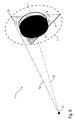
Figure 3A is a sectional view of a second embodiment of the invention, wherein the radiation detector is arranged outside the ring-shaped radiation mask and the radiation mask is tilted relative to the measurement plane. -
Figure 3B is a side view of the second embodiment according toFigure 3A . -
Figure 4A is a sectional view of a third embodiment of the invention in which the radiation mask comprises several sectors which can be selectively moved into the path of the radiation beam or out of the path of the radiation beam. -
Figure 4B is a side view of the embodiment according toFigure 4A . -
Figure 5A is a sectional view of a fourth embodiment of the invention in which a radiation mask is partially ring-shaped and open on one side so that the radiation detector can be arranged outside the radiation mask. -
Figure 5B is a side view of the embodiment according toFigure 5A . -
Figure 6 is a perspective view of a fifth embodiment of the invention in which a ring-shaped anode surrounds the object in the measurement plane wherein an electron beam hits the ring-shaped anode and thereby generates a secondary X-radiation beam. -
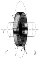
Figure 7 is a perspective view of a sixth embodiment of the invention in which the tomography apparatus generates three-dimensional images of the object. -
Figure 1 shows a sectional view of acomputer tomography apparatus 1 of the so-called third generation, i.e. thecomputer tomography apparatus 1 comprises arotating radiation source 2 and arotating radiation detector 3. - The
computer tomography apparatus 1 can be used for generating sectional images of an object 4 (e.g. a patient) in a measurement plane which is identical with the cutting plane shown in the drawing. - The
radiation source 2 rotates around theobject 4 on acircular path 5 in the direction of the arrow, i.e. counter-clockwise. - Further, the
radiation detector 3 rotates around theobject 4 in the direction of the arrow counter-clockwise, wherein the rotation of theradiation source 2 and the rotation of theradiation detector 3 are synchronized so that theradiation source 2 and theradiation detector 3 are always on opposite sides of theobject 4. - The
radiation source 2 emits a fan-shapedradiation beam 6 which is coplanar with the measurement plane, wherein the fan angle of theradiation beam 6 is sufficiently large that the fan-shapedradiation beam 6 covers the entire lateral extension of theobject 4 in the measurement plane. - Further, the
computer tomography apparatus 1 comprises a ring-shapedradiation mask 7 surrounding theobject 4, wherein theradiation mask 7 is arranged coaxially to thecircular path 5 of theradiation source 2. - The
radiation mask 7 consists of a large number of shielding elements which are arranged along the circumference of the ring-shapedradiation mask 7, so that the individual shielding elements of the radiation mask are separated by radiation windows which can be penetrated by theradiation beam 6. On the contrary, the shielding elements of theradiation mask 7 consist of a material with high radiation absorption properties like lead (Pb) or tungsten (W). Along the circumference of theradiation mask 7, the shielding elements alternate with radiation windows of the same size. - The novel
computer tomography apparatus 1 according to this embodiment differs from conventional computer tomography apparatuses in that the radiation source is outside of the ring-shaped mask and theradiation detector 3 is arranged inside the ring-shapedradiation mask 7, so that theradiation beam 6 passes theradiation mask 7 only once on its path between theradiation source 2 and theradiation detector 3. This is advantageous since it allows a significant reduction of the radiation doses applied during scanning of theobject 4. - It should further be noted that the
radiation detector 3 is flat and extends laterally up to the inside of theradiation mask 7. -
Figure 2 shows a modification of the first embodiment of the invention as shown inFigure 1 , so that reference is made to the above description and the same reference numerals are used for corresponding parts and details. - One characteristic feature of this modification is that the
radiation detector 3 is not flat but curved. -
Figures 3A and 3B illustrate the afore-mentioned second embodiment of the invention, which is similar to the afore-mentioned first embodiment of the invention, so that reference is made to the above description and the same reference numerals are used for corresponding parts and details. - Firstly, it has to be noted that the
radiation detector 3 is arranged outside the ring-shapedradiation mask 7. - Further, it has to be noted that the
radiation mask 7 is arranged in amask plane 8 which is tilted relative to themeasurement plane 9 by a tilt angle α ≈ 20° so that theradiation beam 6 passes theradiation mask 7 on one side only, i.e. between theradiation source 2 and theobject 4, while the other side of theradiation mask 7 is tilted out of themeasurement plane 9 and therefore does not affect theradiation beam 6. - It should further be noted that the
radiation mask 7 carries out a precession movement around acentre axis 10, so that a surface normal 11 of theradiation mask 7 always faces theradiation source 2. -
Figures 4A and 4B illustrate the afore-mentioned third embodiment of the invention, which is similar to the other embodiments of the invention so that reference is made to the above description and the same reference numerals are used for corresponding parts and details. - In this embodiment, the
radiation mask 7 consists ofseveral sectors measurement plane 9 or out of themeasurement plane 9. InFig. 4B , thesector 7A is moved into themeasurement plane 9 while the opposingsector 7B is moved out of themeasurement plane 9. Therefore, thesector 7A of theradiation mask 7 affects theradiation beam 6 while the opposingsector 7B of theradiation mask 7 does not affect theradiation beam 6 since it is moved out of themeasurement plane 9. - The movement of the
sectors radiation mask 7 is controlled in such a way that theradiation beam 6 passes only one of the opposingsectors radiation mask 7. -
Figures 5A and 5B illustrate the afore-mentioned fourth embodiment of the invention which is partially similar to the other embodiments so that reference is made to the above description and the same reference numerals are used for corresponding parts and details. - In this embodiment, the
radiation mask 7 is partially ring-shaped but open on one side. Therefore, theradiation beam 6 passes theradiation mask 7 only once on its path between theradiation source 2 and theradiation detector 3. - During scanning, the
radiation mask 7 is discretely moved around theobject 4 at predetermined angular steps of α = 360°/N wherein N is the number of the shielding elements of the ring-shapedradiation mask 7. - Further,
Figure 6 illustrates the afore-mentioned fifth embodiment of the invention which is partially similar to the other embodiments so that reference is made to the above description and the same reference numerals are used for corresponding parts and details. - In this embodiment of the invention, the
radiation mask 7 consists of a ring-shaped anode which is hit by anelectron beam 12 which is generated by theradiation source 2. Thetarget point 13 of the electron beam on the ring-shaped anode generates secondary X-radiation which penetrates theobject 4. - The
electron beam 12 is moved on the surface shell of a cone surrounding thecentre axis 10 so that thetarget point 13 of theelectron beam 12 on the ring-shaped anode rotates around the object along the circumference of the ring-shapedradiation mask 7. - Finally,
Figure 7 illustrates the sixth embodiment of the invention which is partially similar to the other embodiments so that reference is made to the above description and the same reference numerals are used for corresponding parts and details. - In this embodiment of the invention, the
radiation beam 6 is not restricted to a single measurement plane. Instead, theradiation beam 6 has an axial extension with regard to thecentral axis 10 which is the rotary axis of theradiation beam 6. - Further, the
radiation mask 7 is not restricted to a single measurement plane. Instead, theradiation mask 7 has an axial extension along thecentral axis 10 so that it masks theentire radiation beam 6 along its axial extension. - Further, the
radiation detector 3 has an axial extension along thecentral axis 10. - Therefore, the
tomography apparatus 1 of this embodiment generates three-dimensional images of the object 4 (e.g. a patient) in contrast to the afore-mentioned other embodiments of the invention which merely generate sectional images of the object. - Although the invention has been described with reference to the particular arrangement of parts, features and the like, these are not intended to exhaust all possible arrangements of features, and indeed many other modifications and variations will be ascertainable to those of skill in the art.
-
- 1
- Computer tomography apparatus
- 2
- Radiation source
- 3
- Radiation detector
- 4
- Object
- 5
- Circular path
- 6
- Radiation beam
- 7
- Radiation mask
- 7A, 7B
- Sectors of radiation mask
- 8
- Mask plane
- 9
- Measurement plane
- 10
- Centre axis
- 11
- Surface normal of radiation mask
- 12
- Electron beam
- 13
- Target point
Claims (15)
- Tomography apparatus (1) for generating images of an object (4), comprising:a) a radiation source (2) emitting a radiation beam (6), wherein the radiation beam (6) rotates around the object (4) and penetrates the object (4),b) a radiation detector (3) rotating around the object (4) opposite the radiation source (2), so that the radiation detector (3) detects the radiation beam (6) after penetration of the object (4),c) a radiation mask (7) surrounding the object (4) for masking the radiation beam (6), wherein the radiation mask (7) is arranged in the path of the radiation beam (6) between the radiation source (2) and the radiation detector (3),
characterized in thatd) the radiation beam (6) passes the radiation mask (7) only once between the radiation source (2) and the radiation detector (3). - Tomography apparatus (1) according to claim 1, whereina) the radiation mask (7) is ring-shaped and surrounds the object (4), andb) the radiation detector (3) is arranged inside the ring-shaped radiation mask (7).
- Tomography apparatus (1) according to claim 1, whereina) the radiation beam (6) rotates around the object in a measurement plane (9),b) the radiation mask (7) is ring-shaped and surrounds the object (4) in a mask plane, andc) the radiation detector (3) is arranged outside the ring-shaped radiation mask (7), andd) the mask plane is tilted relative to the measurement plane (9), wherein the mask plane intersects the measurement plane (9), so that the radiation beam (6) passes the radiation mask (7) only once on its path between the radiation source (2) and the radiation detector (3).
- Tomography apparatus (1) according to claim 3, whereina) the radiation mask (7) performs a precession movement around an axis perpendicular to the measurement plane (9), so that a surface normal of the mask plane is always facing the radiation source (2) and/orb) the precession movement of the radiation mask (7) is synchronized with the rotation of the radiation beam (6), and/orc) the mask plane and the measurement plane (9) include a tilt angle of more than 2°, 5°, 7° or 10° and/or less than 60°, 45°, 30° or 25°.
- Tomography apparatus (1) according to claim 1, whereina) the radiation mask (7) is ring-shaped and arranged around the object (4), andb) the radiation detector (3) is arranged outside the ring-shaped radiation mask (7), andc) the radiation mask (7) comprises several adjacent sectors (7A, 7B) which are distributed around the object (4) along the circumference of the ring-shaped radiation mask (7), andd) the sectors (7A, 7B) of the radiation mask (7) can be moved selectively into the path of the radiation beam (6) or out of the path of the radiation beam (6), and/ore) the sectors (7A, 7B) of the radiation mask (7) are moved in such a way that the radiation beam (6) passes the radiation mask (7) only once between the radiation source (2) and the radiation detector (3), and/orf) the sectors (7A, 7B) of the radiation mask (7) on one side of the object (4) are moved into the path of the radiation beam (6) while the sectors (7A, 7B) on the opposite side of the object (4) are moved out of the path of the radiation beam (6), so that the radiation beam (6) passes the radiation mask (7) only once between the radiation source (2) and the radiation detector (3).
- Tomography apparatus (1) according to claim 5, whereina) the sectors (7A, 7B) of the radiation mask (7) are movable orthogonally to the mask plane or parallel to the rotary axis of the radiation beam (6), and/orb) the radiation mask (7) comprises N shielding elements which are separated by radiation windows, wherein the shielding elements are arranged around the object (4), andc) there are n selectively movable sectors (7A, 7B) of the radiation mask (7) each extending over a multiple of an angle of 360°/N around the object (4), andd) the relationship between the number n of the sectors (7A, 7B) and the number N of the shielding elements is as follows:

- Tomography apparatus (1) according to claim 1, wherein the radiation mask (7) is open on one side thereby avoiding a second collimation of the radiation beam (6) on its path to the radiation detector (3).
- Tomography apparatus (1) according to claim 7, whereina) the radiation mask (7) is discretely moved around the object (4) at predetermined angular steps α, and/orb) the radiation mask (7) comprises N shielding elements which are separated by radiation windows, wherein the shielding elements are annularly arranged on an arc spanning an angular sector of a size β around the object (4), andc) the angular steps α are multiples of β/N, wherein the size β of the mask may be between 5° and 355°.
- Tomography apparatus (1) according to claim 1, whereina) the radiation source (2) comprises a ring-shaped anode surrounding the object (4), preferably in the measurement plane (9),b) the radiation source (2) comprises an electron source directing an electron beam (12) onto the ring-shaped anode thereby generating the radiation beam (6) as a secondary X-radiation beam (6),c) the ring-shaped anode comprises several anode elements which are spaced apart and distributed around the object (4) so that the anode constitutes or imitates the radiation mask (7),d) the electron beam (12) is moved around the ring-shaped anode so that the secondary X-radiation beam (6) rotates around the object (4).
- Tomography apparatus (1) according to claim 9, whereina) the radiation detector (3) rotates around the object (4), and/orb) the electron beam and the radiation detector (3) are moved in the same direction and with the same angular speed around the object (4), and/orc) the electron beam is aligned substantially transverse to the measurement plane (9).
- Tomography apparatus (1) according to one of the preceding claims, whereina) the radiation beam (6) has an axial extension with regard to its rotary axis (10), andb) the radiation beam (6) penetrates the object (4) in a three-dimensional area so that the tomography apparatus (1) generates three-dimensional images of the object (4), and/orc) the radiation mask (7) has an axial extension with regard to the rotary axis (10) of the radiation beam (6) so that it masks the radiation beam (6) not only in a single plane but along the rotary axis (10) of the radiation beam (6), and/ord) the radiation detector (3) has an axial extension with regard to the rotary axis (10) of the radiation beam (6) so that it detects the radiation beam (6) not only in a single plane but along the rotary axis (10) of the radiation beam (6).
- Tomography apparatus (1) according to one of the preceding claims, wherein thea) radiation detector (3) is flat or curved, and/orb) the radiation mask (7) is fixed, and/orc) the radiation detector (3) is arranged inside the ring-shaped radiation mask (7), and/ord) the radiation beam (6) is fan-shaped and substantially co-planar with the measurement plane (9), and/ore) the radiation beam (6) is cone-shaped and penetrates the object (4) through windows of the radiation mask (7), and/orf) the radiation detector (3) is radiation-sensitive along a predetermined extension along the measurement plane (9), and/org) the radiation detector (3) is radiation-sensitive along a predetermined extension in two dimensions, and/orh) the radiation is X-radiation, and/ori) the radiation mask (7) is made of a material which is radiation absorbing, particularly lead or tungsten.
- Tomography apparatus (1) according to one of the preceding claims, whereina) the radiation source (2) and the radiation detector (3) are arranged on a gantry on opposite sides of the object (4), wherein the gantry rotates in the measurement plane (9), and/orb) the radiation beam (6), the radiation source (2) and the radiation detector (3) carry out coaxial rotary motions, and/orc) the radiation source (2) rotates around the object (4), and/ord) the radiation detector (3) rotates in the same direction and at the same angular speed around the object (4) as the radiation beam (6), and/ore) the radiation beam (6) and the radiation detector (3) rotate around the object (4) with the same angular speed and in the same direction, so that the radiation source (2) and the radiation detector (3) are always on opposite sides of the object (4), and/orf) the rotation of the radiation detector (3) is synchronized with the rotation of the radiation beam (6) or the radiation source (2), so that the radiation detector (3) detects the radiation beam (6) after penetration of the object (4), and/org) the tomography apparatus (1) is a computer tomography apparatus (1) of the third generation, i.e. a rotate/rotate device comprising a rotating radiation source (2) and a rotation radiation detector (3).
- Tomography method for generating sectional images of an object (4) in a measurement plane (9), comprising the following steps:a) Emitting a radiation beam (6) by means of a radiation source (2), wherein the radiation beam (6) rotates in the measurement plane (9) relative to the object (4) and penetrates the object (4),b) Detecting the radiation beam (6) by means of a radiation detector (3) after penetration of the object (4),c) Masking the radiation beam (6) by means of a radiation mask (7) which surrounds the object (4) and which is arranged in the path of the radiation beam (6) between the radiation source (2) and the radiation detector (3),characterized in thatd) the radiation beam (6) passes the radiation mask (7) only once between the radiation source (2) and the radiation detector (3).
- Tomography method according to claim 14, whereina) the radiation mask (7) is ring-shaped and the radiation detector (3) is arranged inside the ring-shaped radiation mask (7), orb) the radiation mask (7) comprises several adjacent sectors which are distributed around the object (4) along the circumference of the ring-shaped radiation mask (7), wherein the sectors are selectively moved into the path of the radiation beam (6) or out of the path of the radiation beam (6), so that the radiation beam (6) passes the radiation mask (7) only once between the radiation source (2) and the radiation detector (3), orc) the radiation mask (7) is ring-shaped and surrounds the object (4) in a mask plane (8), which is tilted relative to the measurement plane (9), wherein the mask plane (8) intersects the measurement plane (9), so that the radiation beam (6) passes the radiation mask (7) only once on its path between the radiation source (2) and the radiation detector (3), ord) the radiation source (2) comprises a ring-shaped anode surrounding the object (4) in the measurement plane (9) and further an electron source directing an electron beam onto the ring-shaped anode thereby generating the radiation beam (6) as a secondary X-radiation beam (6), wherein the ring-shaped anode comprises several anode elements which are spaced apart and distributed around the object (4) so that the anode constitutes the radiation mask (7), while the electron beam is moved around the ring-shaped anode so that the secondary X-radiation beam (6) rotates around the object (4).
Priority Applications (5)
| Application Number | Priority Date | Filing Date | Title |
|---|---|---|---|
| EP09006483A EP2250967A1 (en) | 2009-05-13 | 2009-05-13 | Tomography apparatus and tomography method |
| JP2012510150A JP5616436B2 (en) | 2009-05-13 | 2010-05-10 | Tomography apparatus and tomography method |
| US13/320,175 US8971481B2 (en) | 2009-05-13 | 2010-05-10 | Tomography apparatus and tomography method |
| EP10721685A EP2429404A1 (en) | 2009-05-13 | 2010-05-10 | Tomography apparatus and tomography method |
| PCT/EP2010/002862 WO2010130394A1 (en) | 2009-05-13 | 2010-05-10 | Tomography apparatus and tomography method |
Applications Claiming Priority (1)
| Application Number | Priority Date | Filing Date | Title |
|---|---|---|---|
| EP09006483A EP2250967A1 (en) | 2009-05-13 | 2009-05-13 | Tomography apparatus and tomography method |
Publications (1)
| Publication Number | Publication Date |
|---|---|
| EP2250967A1 true EP2250967A1 (en) | 2010-11-17 |
Family
ID=41208665
Family Applications (2)
| Application Number | Title | Priority Date | Filing Date |
|---|---|---|---|
| EP09006483A Withdrawn EP2250967A1 (en) | 2009-05-13 | 2009-05-13 | Tomography apparatus and tomography method |
| EP10721685A Withdrawn EP2429404A1 (en) | 2009-05-13 | 2010-05-10 | Tomography apparatus and tomography method |
Family Applications After (1)
| Application Number | Title | Priority Date | Filing Date |
|---|---|---|---|
| EP10721685A Withdrawn EP2429404A1 (en) | 2009-05-13 | 2010-05-10 | Tomography apparatus and tomography method |
Country Status (4)
| Country | Link |
|---|---|
| US (1) | US8971481B2 (en) |
| EP (2) | EP2250967A1 (en) |
| JP (1) | JP5616436B2 (en) |
| WO (1) | WO2010130394A1 (en) |
Families Citing this family (2)
| Publication number | Priority date | Publication date | Assignee | Title |
|---|---|---|---|---|
| EP2976626A4 (en) * | 2013-03-22 | 2016-09-21 | Univ New York | SYSTEM, METHOD AND COMPUTER-ACCESSIBLE MEDIUM FOR MODULATION OF INTENSITY OF X-RAY BEAM |
| WO2023123301A1 (en) * | 2021-12-31 | 2023-07-06 | Shenzhen Xpectvision Technology Co., Ltd. | Imaging systems with rotating image sensors |
Citations (3)
| Publication number | Priority date | Publication date | Assignee | Title |
|---|---|---|---|---|
| US4315157A (en) * | 1980-05-01 | 1982-02-09 | The University Of Alabama In Birmingham | Multiple beam computed tomography (CT) scanner |
| EP1677253A1 (en) * | 2004-12-30 | 2006-07-05 | GSF-Forschungszentrum für Umwelt und Gesundheit GmbH | Method and device of reconstructing an (n+1)-dimensional image function from radon data |
| EP1780676A1 (en) * | 2005-10-25 | 2007-05-02 | GSF-Forschungszentrum für Umwelt und Gesundheit GmbH | Imaging method and device with dual reading scanner |
Family Cites Families (9)
| Publication number | Priority date | Publication date | Assignee | Title |
|---|---|---|---|---|
| JPS5542640A (en) * | 1978-09-21 | 1980-03-26 | Nippon Electron Optics Lab | Xxray tomogram camera device |
| JPS646898A (en) * | 1987-06-30 | 1989-01-11 | Yokogawa Medical Syst | Collimator for x-ray tomographic apparatus |
| JPH1128201A (en) * | 1997-07-10 | 1999-02-02 | Hitachi Medical Corp | X-ray ct |
| DE19905974A1 (en) * | 1999-02-12 | 2000-09-07 | Siemens Ag | Computer tomography scanning method using multi-line detector |
| JP2004283343A (en) * | 2003-03-20 | 2004-10-14 | Toshiba Corp | X-ray CT apparatus and data acquisition method |
| US7885375B2 (en) * | 2004-02-27 | 2011-02-08 | General Electric Company | Method and system for X-ray imaging |
| EP1727092A1 (en) * | 2005-05-23 | 2006-11-29 | GSF-Forschungszentrum für Umwelt und Gesundheit GmbH | Method and device for imaging tomography |
| WO2007004859A1 (en) * | 2005-07-03 | 2007-01-11 | Widee B.V. | Coupling between two bodies |
| US7760849B2 (en) * | 2006-04-14 | 2010-07-20 | William Beaumont Hospital | Tetrahedron beam computed tomography |
-
2009
- 2009-05-13 EP EP09006483A patent/EP2250967A1/en not_active Withdrawn
-
2010
- 2010-05-10 WO PCT/EP2010/002862 patent/WO2010130394A1/en not_active Ceased
- 2010-05-10 EP EP10721685A patent/EP2429404A1/en not_active Withdrawn
- 2010-05-10 US US13/320,175 patent/US8971481B2/en not_active Expired - Fee Related
- 2010-05-10 JP JP2012510150A patent/JP5616436B2/en not_active Expired - Fee Related
Patent Citations (4)
| Publication number | Priority date | Publication date | Assignee | Title |
|---|---|---|---|---|
| US4315157A (en) * | 1980-05-01 | 1982-02-09 | The University Of Alabama In Birmingham | Multiple beam computed tomography (CT) scanner |
| EP1677253A1 (en) * | 2004-12-30 | 2006-07-05 | GSF-Forschungszentrum für Umwelt und Gesundheit GmbH | Method and device of reconstructing an (n+1)-dimensional image function from radon data |
| EP1780676A1 (en) * | 2005-10-25 | 2007-05-02 | GSF-Forschungszentrum für Umwelt und Gesundheit GmbH | Imaging method and device with dual reading scanner |
| WO2007048590A1 (en) | 2005-10-25 | 2007-05-03 | Helmholtz Zentrum München Deutsches Forschungszentrum Für Gesundheit Und Umwelt (Gmbh) | Imaging method and device with dual reading scanner |
Also Published As
| Publication number | Publication date |
|---|---|
| WO2010130394A1 (en) | 2010-11-18 |
| EP2429404A1 (en) | 2012-03-21 |
| JP2012526568A (en) | 2012-11-01 |
| US20130039459A1 (en) | 2013-02-14 |
| JP5616436B2 (en) | 2014-10-29 |
| US8971481B2 (en) | 2015-03-03 |
Similar Documents
| Publication | Publication Date | Title |
|---|---|---|
| CN101536134B (en) | Multi-focal-spot X-ray tube with multi-electron beam operation unit | |
| US6434219B1 (en) | Chopper wheel with two axes of rotation | |
| US7031434B1 (en) | Method of manufacturing, and a collimator mandrel having variable attenuation characteristics for a CT system | |
| WO2005008716A3 (en) | Cylindrical x-ray tube for computed tomography imaging | |
| EP3313291B1 (en) | A system for generating and collimating an x-ray beam | |
| CN109691238B (en) | Systems and methods for improving penetration of radiology imaging scanners | |
| JPH09215685A (en) | Pre-patient collimator | |
| EP2347710B1 (en) | Apparatus for wide coverage computed tomography | |
| JP5426089B2 (en) | X-ray tube and X-ray CT apparatus | |
| US7340029B2 (en) | X-ray computed tomography apparatus for fast image acquisition | |
| US9031192B2 (en) | Ray emission device and imaging system having the same | |
| KR102139661B1 (en) | Computed tomography system comprising rotatable collimator | |
| US8284901B2 (en) | Apparatus and method for improved transient response in an electromagnetically controlled x-ray tube | |
| EP2250967A1 (en) | Tomography apparatus and tomography method | |
| JP5632652B2 (en) | X-ray bone density measuring device | |
| EP3442001B1 (en) | A circular x-ray tube and an x-ray instrument comprising the circular x-ray tube | |
| US8385507B2 (en) | Apparatus and method for improved transient response in an electromagnetically controlled X-ray tube | |
| WO2019214724A1 (en) | X-ray generator for hybrid scanning, hybrid examination apparatus, and examination method | |
| HK1199757B (en) | Ct equipment and method thereof | |
| JPS6143816B2 (en) |
Legal Events
| Date | Code | Title | Description |
|---|---|---|---|
| PUAI | Public reference made under article 153(3) epc to a published international application that has entered the european phase |
Free format text: ORIGINAL CODE: 0009012 |
|
| AK | Designated contracting states |
Kind code of ref document: A1 Designated state(s): AT BE BG CH CY CZ DE DK EE ES FI FR GB GR HR HU IE IS IT LI LT LU LV MC MK MT NL NO PL PT RO SE SI SK TR |
|
| AX | Request for extension of the european patent |
Extension state: AL BA RS |
|
| STAA | Information on the status of an ep patent application or granted ep patent |
Free format text: STATUS: THE APPLICATION IS DEEMED TO BE WITHDRAWN |
|
| 18D | Application deemed to be withdrawn |
Effective date: 20110518 |