EP2249598A1 - Mobile communication system, base station device, user equipment, and method - Google Patents
Mobile communication system, base station device, user equipment, and method Download PDFInfo
- Publication number
- EP2249598A1 EP2249598A1 EP09713830A EP09713830A EP2249598A1 EP 2249598 A1 EP2249598 A1 EP 2249598A1 EP 09713830 A EP09713830 A EP 09713830A EP 09713830 A EP09713830 A EP 09713830A EP 2249598 A1 EP2249598 A1 EP 2249598A1
- Authority
- EP
- European Patent Office
- Prior art keywords
- control information
- transmission signal
- cycle
- unit configured
- downlink
- Prior art date
- Legal status (The legal status is an assumption and is not a legal conclusion. Google has not performed a legal analysis and makes no representation as to the accuracy of the status listed.)
- Withdrawn
Links
- 238000010295 mobile communication Methods 0.000 title claims abstract description 23
- 238000000034 method Methods 0.000 title claims description 10
- 230000005540 biological transmission Effects 0.000 claims abstract description 67
- 238000004891 communication Methods 0.000 claims abstract description 14
- 230000007274 generation of a signal involved in cell-cell signaling Effects 0.000 claims abstract description 11
- 238000000605 extraction Methods 0.000 claims description 11
- 239000000284 extract Substances 0.000 claims description 7
- 101000741965 Homo sapiens Inactive tyrosine-protein kinase PRAG1 Proteins 0.000 description 7
- 102100038659 Inactive tyrosine-protein kinase PRAG1 Human genes 0.000 description 7
- 208000037918 transfusion-transmitted disease Diseases 0.000 description 6
- 230000003044 adaptive effect Effects 0.000 description 3
- 238000012986 modification Methods 0.000 description 3
- 230000004048 modification Effects 0.000 description 3
- 230000011664 signaling Effects 0.000 description 3
- 230000004075 alteration Effects 0.000 description 2
- 230000007423 decrease Effects 0.000 description 2
- 238000006467 substitution reaction Methods 0.000 description 2
- 230000001174 ascending effect Effects 0.000 description 1
- 230000003111 delayed effect Effects 0.000 description 1
- 238000010586 diagram Methods 0.000 description 1
- 230000000977 initiatory effect Effects 0.000 description 1
- 238000011835 investigation Methods 0.000 description 1
- 230000007774 longterm Effects 0.000 description 1
- 238000013507 mapping Methods 0.000 description 1
- 239000013598 vector Substances 0.000 description 1
Images


Classifications
-
- H—ELECTRICITY
- H04—ELECTRIC COMMUNICATION TECHNIQUE
- H04L—TRANSMISSION OF DIGITAL INFORMATION, e.g. TELEGRAPHIC COMMUNICATION
- H04L1/00—Arrangements for detecting or preventing errors in the information received
- H04L1/12—Arrangements for detecting or preventing errors in the information received by using return channel
- H04L1/16—Arrangements for detecting or preventing errors in the information received by using return channel in which the return channel carries supervisory signals, e.g. repetition request signals
- H04L1/18—Automatic repetition systems, e.g. Van Duuren systems
- H04L1/1829—Arrangements specially adapted for the receiver end
- H04L1/1854—Scheduling and prioritising arrangements
-
- H—ELECTRICITY
- H04—ELECTRIC COMMUNICATION TECHNIQUE
- H04L—TRANSMISSION OF DIGITAL INFORMATION, e.g. TELEGRAPHIC COMMUNICATION
- H04L1/00—Arrangements for detecting or preventing errors in the information received
- H04L1/12—Arrangements for detecting or preventing errors in the information received by using return channel
- H04L1/16—Arrangements for detecting or preventing errors in the information received by using return channel in which the return channel carries supervisory signals, e.g. repetition request signals
- H04L1/18—Automatic repetition systems, e.g. Van Duuren systems
- H04L1/1829—Arrangements specially adapted for the receiver end
- H04L1/1861—Physical mapping arrangements
-
- H—ELECTRICITY
- H04—ELECTRIC COMMUNICATION TECHNIQUE
- H04L—TRANSMISSION OF DIGITAL INFORMATION, e.g. TELEGRAPHIC COMMUNICATION
- H04L5/00—Arrangements affording multiple use of the transmission path
- H04L5/003—Arrangements for allocating sub-channels of the transmission path
- H04L5/0053—Allocation of signalling, i.e. of overhead other than pilot signals
- H04L5/0055—Physical resource allocation for ACK/NACK
-
- H—ELECTRICITY
- H04—ELECTRIC COMMUNICATION TECHNIQUE
- H04L—TRANSMISSION OF DIGITAL INFORMATION, e.g. TELEGRAPHIC COMMUNICATION
- H04L5/00—Arrangements affording multiple use of the transmission path
- H04L5/003—Arrangements for allocating sub-channels of the transmission path
- H04L5/0058—Allocation criteria
- H04L5/006—Quality of the received signal, e.g. BER, SNR, water filling
-
- H—ELECTRICITY
- H04—ELECTRIC COMMUNICATION TECHNIQUE
- H04L—TRANSMISSION OF DIGITAL INFORMATION, e.g. TELEGRAPHIC COMMUNICATION
- H04L5/00—Arrangements affording multiple use of the transmission path
- H04L5/003—Arrangements for allocating sub-channels of the transmission path
- H04L5/0058—Allocation criteria
- H04L5/0069—Allocation based on distance or geographical location
-
- H—ELECTRICITY
- H04—ELECTRIC COMMUNICATION TECHNIQUE
- H04L—TRANSMISSION OF DIGITAL INFORMATION, e.g. TELEGRAPHIC COMMUNICATION
- H04L5/00—Arrangements affording multiple use of the transmission path
- H04L5/003—Arrangements for allocating sub-channels of the transmission path
- H04L5/0078—Timing of allocation
- H04L5/0082—Timing of allocation at predetermined intervals
-
- H—ELECTRICITY
- H04—ELECTRIC COMMUNICATION TECHNIQUE
- H04L—TRANSMISSION OF DIGITAL INFORMATION, e.g. TELEGRAPHIC COMMUNICATION
- H04L5/00—Arrangements affording multiple use of the transmission path
- H04L5/0091—Signalling for the administration of the divided path, e.g. signalling of configuration information
-
- H—ELECTRICITY
- H04—ELECTRIC COMMUNICATION TECHNIQUE
- H04W—WIRELESS COMMUNICATION NETWORKS
- H04W72/00—Local resource management
- H04W72/20—Control channels or signalling for resource management
- H04W72/23—Control channels or signalling for resource management in the downlink direction of a wireless link, i.e. towards a terminal
-
- H—ELECTRICITY
- H04—ELECTRIC COMMUNICATION TECHNIQUE
- H04W—WIRELESS COMMUNICATION NETWORKS
- H04W72/00—Local resource management
- H04W72/50—Allocation or scheduling criteria for wireless resources
- H04W72/54—Allocation or scheduling criteria for wireless resources based on quality criteria
Definitions
- the present invention relates to the technical field of mobile communications and more particularly relates to a mobile communication system, a base station apparatus, a user apparatus and a method that use the next generation mobile communication techniques.
- W-CDMA Wideband-Code Division Multiplexing Access
- LTE Long Term Evolution
- HSDPA High Speed Downlink Packet Access
- HSUPA High Speed Uplink Packet Access
- FIG. 1 illustrates a schematic view of a mobile communication system.
- the mobile communication system includes a cell 50, user apparatuses 100 1 , 100 2 , 100 3 residing within the cell 50, a base station apparatus wirelessly communicating to the user apparatuses, an upper node 300 connected to the base station apparatus and a core network 400 connected to the upper node.
- the upper node 300 may be a radio network controller (RNC), an access gateway (aGW), a mobility management entity (MME) and so on, for example.
- RNC radio network controller
- aGW access gateway
- MME mobility management entity
- communications are conducted by assigning one or more resource blocks to the user apparatuses in any of uplinks and downlinks.
- the resource blocks are shared among a large number of user apparatuses within the system.
- the base station apparatus determines which of the several user apparatuses the resource blocks are assigned for every subframe having a time period such as 1 ms.
- the subframe may be referred to as a transmission time interval (TTI).
- TTI transmission time interval
- the assignment of radio resources is called scheduling.
- the base station apparatus transmits shared channels to the scheduled user apparatuses in one or more resource blocks.
- the shared channel may be referred to as a PDSCH (Physical Downlink Shared Channel).
- the scheduled user apparatuses transmit shared channels to the base station apparatus in one or more resource blocks.
- the shared channel may be referred to as a PUSCH (Physical Uplink Shared Channel).
- a downlink control channel for use in the signaling may include a PDCCH (Physical Downlink Control Channel) or a DL-L1/L2 control channel.
- the PDCCH may include information pieces such as a downlink scheduling grant, an uplink scheduling grant, an ACK/NACK (Acknowledgement/Non-Acknowledgement information) and a transmission power control command bit, for example. See non-patent document 2 in details, for example.
- the downlink scheduling grant includes information on downlink shared channels, for example.
- the downlink scheduling grant may includes information pieces such as assignment information of downlink resource blocks, identification of user apparatuses (UE-ID), the number of streams, information on precoding vectors, a data size, a modulation scheme and information on HARQ (Hybrid Automatic Repeat reQuest).
- UE-ID identification of user apparatuses
- HARQ Hybrid Automatic Repeat reQuest
- the uplink scheduling grant includes information on uplink shared channels, for example.
- the uplink scheduling grant may information pieces such as assignment information of uplink resources, identification of user apparatuses, a data size, a modulation scheme, uplink transmission power information and demodulation reference signal information in uplink MIMO.
- the ACK/NACK indicates whether the PUSCH transmitted in uplinks has to be retransmitted.
- uplinks user data (normal data signals) and the associated control information are transmitted in the PUSCH. Also separately from the PUSCH, downlink CQI (Channel Quality Indicator), ACK/NACK for the PDSCH and so on are transmitted in a PUCCH (Physical Uplink Control Channel). The CQI is used for scheduling and AMCS (Adaptive Modulation and Coding Scheme) in the PDSCH.
- a RACH Random Access Channel
- signals indicative of assignment requests of uplink and downlink radio resources may be transmitted if necessary.
- the mobile communication system since the mobile communication system includes radio links, there arise some types of signal delay that may not be caused in wired systems.
- the signal delay may be referred to as radio interface delay or air interface delay. From the viewpoint of faster communications, it is necessary to reduce the signal delay as much as possible.
- FIG. 2 illustrates details of the air interface delay.
- the air interface delay includes (a) transmission delay, (b) retransmission delay and (c) reception delay.
- the transmission delay (a) represents a time period from transmission initiation to transmission completion of all signals. For example, in transmission of data equivalent to 1 TTI, a time period equivalent to about 1.5 TTI is required in whole considering delay for transmission operation.
- the retransmission delay (b) represents delay for retransmission control (HARQ).
- the retransmission is conducted after 6 TTIs.
- the reception delay (c) represents a time period required to receive and modulate transmitted data. In reception of data equivalent to 1 TTI, for example, a time period equivalent to about 2 TTIs may be required.
- the air interface delay can be estimated to be about 6.5 TTIs in whole. In this manner, the air interface delay is proportional to the TTI. This means that reduction in the TTI period can reduce the air interface delay. For example, if the TTI is shortened from 1.0 ms to 0.5 ms, the above air interface delay may be reduced from 6.5 ms to 3.25 ms.
- the applied assignment method must be signaled to user apparatuses for each of the subframes. Even if the TTI is shortened, the information amount required for the signaling may not be significantly changed.
- TTIs 1.0 ms.
- One or more of a large number of (frequency) resource blocks are assigned to certain users. The assignment methods are signaled in a L1/L2 control channel.
- the TTI is shortened by half while the transmission frequency of the L1/L2 control channel is doubled.
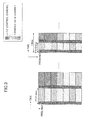
- the proportion of the amount of control information per unit time such as 1.0 ms (proportion of overhead) increases for shorter TTI, and accordingly the data throughput decreases. From the viewpoint of the data throughput, it is desirable to make the TTI longer and decrease the overhead proportion per unit time, as illustrated in the left side in FIG. 3 .
- Non-patent document 1 3GPP R1-070103, Downlink L1/L2 Control Signaling Channel Structure: Coding
- Non-patent document 2 Yoshihisa Kishiyama, Kenichi Higuchi, Hiroyuki Atarashi and Mamoru Sawahashi, "Investigations on Radio Parameter Set for OFDM Radio Access in Evolved UTRA Downlink", IEICE Tech. Rep., vol. 105, no. 240, RCS2005-72, pp. 49-54, Aug. 2005
- One object of the present invention is to reduce air interface delay while suppressing overhead increase per unit time.
- a communication apparatus in a mobile communication system includes a first control information generation unit configured to generate first control information including acknowledgement information on a previously received data channel, a second control information generation unit configured to generate second control information including scheduling information on radio resources and a transmission signal generation unit configured to generate a transmission signal including a lower layer control channel including at least one of the first control information and the second control information.
- the transmission signal generation unit generates the transmission signal to transmit the first control information in any of subframes arriving at a first cycle and to transmit the second control information in any of subframes arriving at a second cycle longer than the first cycle.
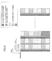
- FIG. 4 illustrates operation principle of an embodiment.
- a short subframe is set.
- a conventional subframe is equal to 1.0 ms while the short subframe of the present embodiment is equal to 0.5 ms.
- these numerical values are simply illustrative, and any other appropriate numerical values may be used.
- the subframe may be set to 0.1 ms.
- information transmitted in downlink control channels is classified into first control information and second control information.
- the first control information includes retransmission information on uplink data channels that a base station apparatus received beforehand.
- the retransmission information indicates information for use in retransmission control such as packet numbers, puncture patterns of transmitted packets and so on.
- the retransmission information may include acknowledgement information represented as ACK indicative of no need of retransmission or NACK indicative of need of retransmission.
- the second control information may include control information other than the retransmission control information.
- the second control information may include downlink and/or uplink scheduling information, AMC information, transmission power control information (TPC information) and so on.
- AMC information indicates which of predefined combinations of data modulation schemes and channel coding rates is used in AMCS (Adaptive Modulation and Coding Scheme).
- the first control information can be transmitted at the shortest cycle while the apparent TTI length for the second control information can be adaptively changed.
- TTI information indicates the value of N where N is a natural number greater than or equal to 2.
- the present embodiment is preferred to reduce retransmission delay effectively.
- the second control information is transmitted at the same frequency as a conventional one, overhead increase due to the second control information might be substantially equal to 0.
- the proportion of the overhead per 1.0 ms is equal to "1" in the case illustrated in the left side in FIG. 3
- the proportion may be equal to "2" in the case of the right side in FIG. 3 and to "1+ ⁇ " in the case of FIG. 4 .
- ⁇ has an information amount equivalent to ACK/NACK, ⁇ may be much smaller than "1' ⁇ ( ⁇ 1).
- the overhead increase can be highly alleviated compared to the case of the right side in FIG. 3 .
- TTI first cycle
- NXTTI second cycle
- opportunities to transmit the retransmission control information are ensured with higher frequencies, and other control information is transmitted with lower frequencies. In this manner, it is possible to reduce the retransmission delay and accordingly the air interface delay while suppressing the overhead increase.
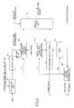
- FIG. 5 illustrates a base station apparatus according to one embodiment of the present invention.
- a TTI control unit 51 a scheduler 52, a lower layer control channel generation unit 53, an upper layer control information generation unit 54, a broadcast information generation unit 55, a downlink data channel generation unit 56, a multiplexing unit 57 and an uplink control information extraction unit 58 are illustrated.
- the TTI control unit 51 determines the value of N indicated in TTI information depending on states.
- the TTI information indicative of the relationship between the first cycle and the second cycle may be transmitted (i) as lower layer control information, (ii) as upper layer control information to individual users, or (iii) as broadcast information being user common information to user apparatuses. From the viewpoint of user-by-user control, (i) and (ii) are desirable. From the viewpoint of adaptive and frequent modifications, (i) is desirable. From the viewpoint of overhead reduction in downlinks, (iii) is desirable.
- the scheduler 52 schedules radio resources based on the TTI information (the value of N) determined by the TTI control unit 51.
- the scheduling may be conducted in any known appropriate algorithm in this technical field. As one example, the scheduling may be conducted in accordance with maximum C/I method or proportional fairness method.
- Downlink and/or uplink scheduling information is supplied to the lower layer control channel generation unit 53. Since the scheduling information indicates correspondence between transmitted information and frequency and time, the correspondence is supplied to the multiplexing unit 57 as mapping information.
- the scheduler 52 determines a data modulation scheme and a channel coding rate to be applied to a data channel and supplies them as AMC information to the downlink data channel generation unit 56.
- the lower layer control channel generation unit 53 generates control information to be transmitted in a downlink L1/L2 control channel and performs predefined channel coding and data modulation on the control information, for example, to generate a lower layer control channel such as a L1/L2 control channel.
- the control information includes the above-mentioned first and second control information.
- the first control information includes at least acknowledgement information for uplink shared data channels previously received at the base station apparatus.
- the first control information may include information for use in retransmission control such as a packet number and a puncture pattern of transmitted packets.
- the second control information may include control information other than the retransmission control related information.
- the upper layer control information generation unit 54 generates information such as L3 control information and supplies the information to the downlink data channel generation unit 56.
- the broadcast information generation unit 55 generates broadcast information (BCH) to broadcast to user apparatuses within a cell and supplies the broadcast information to the downlink data channel generation unit 56.
- BCH broadcast information
- the downlink data channel generation unit 56 receives user data, upper layer control information and broadcast information and generates downlink data channels by performing data modulation and channel coding on signals including the data and information.
- the multiplexing unit 57 multiplexes the lower layer control channels and the downlink data channels.
- the multiplexing is conducted based on time division multiplexing and frequency division multiplexing.
- the multiplexed signal may have a format illustrated in FIG. 4 .
- the uplink control information extraction unit 58 extracts and restores uplink control information from received uplink signals.
- FIG. 6 illustrates a user apparatus according to one embodiment of the present invention.
- a lower layer control information restoration unit 61 a downlink data channel restoration unit 62 and an uplink data channel generation unit 63 are illustrated.
- the lower layer control information restoration unit 61 decodes and demodulates a lower layer control channel received from the base station apparatus and extracts control information.
- the control information includes first control information (e.g., a packet number, a puncture pattern and ACK/NACK) and second control information (other control information) .
- the first control information is supplied to the uplink data channel generation unit 63.
- Downlink scheduling information in the second control information is supplied to the downlink data channel restoration unit 62.
- Uplink scheduling grant in the second control information is supplied to the uplink data channel generation unit 63.
- the TTI information is also extracted in the lower layer control information restoration unit 61.
- the downlink data channel restoration unit 62 extracts a downlink data channel in accordance with downlink scheduling information and restores the downlink data channel through demodulation and decoding.
- the TTI information is extracted as upper layer control information or broadcast information (the above-mentioned case (ii) or (iii)) at the downlink data channel restoration unit 62.
- the uplink data channel generation unit 63 generates an uplink data channel in accordance with an uplink scheduling grant.
- the uplink data channel generation unit 63 generates a new uplink data channel or an uplink data channel for retransmission depending on retransmission control information (ACK/NACK) transmitted from the lower layer control information restoration unit 61.
- ACK/NACK retransmission control information
- the TTI information determined by the TTI control unit 51 in FIG. 5 may be uniform within the mobile communication system or for each cell or may be different for individual users. More generally, the TTI information indicating how many multiples of the first cycle the second cycle corresponds to (the multiple is denoted as N) may be adaptively determined for each user depending on various conditions. In other words, it may be determined based on the various conditions how often a transmission opportunity of the control information (particularly the second control information) should be ensured.
- the conditions may include, but not limited to, (1) reception SINR of uplink pilot channels, (2) CQI (Channel Quality Indicator) derived from reception SINR of downlink pilot channels and reported from user apparatuses, (3) distances between users and the base station apparatus, (4) user mobility (Doppler frequency), (5) user's requested signal quality (QoS) and so on.
- the value of N may be arbitrarily determined for a certain user by an operator or others.
- the determination criteria (1)-(5) may be applied singular or in combinations. Also, other determination criteria may be applied.
- control information is classified into the first and second control information, and the first control information and the second control information are transmitted in subframes arriving in the first cycle and the second cycle, respectively.
- control information may be classified into the first through third control information, and the first through third control information may be transmitted in subframes arriving in the first through third cycles, respectively.
- FIG. 7 illustrates cycle variations depending on distances between a user and a base station where the control information is classified into three or more control information.
- the distance L increases in ascending order of numbers in the suffix (L 1 ⁇ L 2 ⁇ L 3 ⁇ L 4 ⁇ ).
- the above and other determination criteria may be used.
- the control information may be classified into any number of control information pieces, and any number of values of N may be used.
- the first and second control information are transmitted in downlink, but the present invention is also applicable to the control information transmitted in uplink.
- a user apparatus transmits the uplink control information in accordance with the TTI information determined at a base station apparatus.
- the uplink first control information including retransmission information on downlink data channels or others is transmitted in subframes frequently arriving at the first cycle.
- the uplink second control information other than the retransmission control information is transmitted in subframes arriving at the second cycle. From the technical viewpoint, a user apparatus may determines the TTI information. However, it is desirable that a base station apparatus makes final decision on the TTI information from the viewpoint of system security and appropriate management.
- the present invention may be applied to any appropriate mobile communication system where radio resources are shared among users through scheduling.
- the present invention may be applied to HSDPA/HSUPA scheme W-CDMA systems, LTE scheme systems, IMT-Advanced systems, WiMAX scheme systems, Wi-Fi scheme systems and so on.
Landscapes
- Engineering & Computer Science (AREA)
- Signal Processing (AREA)
- Computer Networks & Wireless Communication (AREA)
- Quality & Reliability (AREA)
- Mobile Radio Communication Systems (AREA)
Abstract
Description
- The present invention relates to the technical field of mobile communications and more particularly relates to a mobile communication system, a base station apparatus, a user apparatus and a method that use the next generation mobile communication techniques.
- In this type of technical field, mobile communication schemes, which may become successors of the so-called third generation, are being discussed by standardization group 3GPP for W-CDMA (Wideband-Code Division Multiplexing Access) scheme. Particularly, LTE (Long Term Evolution) and further successor mobile communication schemes are being intensively discussed as successors of the W-CDMA scheme, HSDPA (High Speed Downlink Packet Access) scheme, HSUPA (High Speed Uplink Packet Access) scheme and so on.
-
FIG. 1 illustrates a schematic view of a mobile communication system. The mobile communication system includes acell 50, user apparatuses 1001, 1002, 1003 residing within thecell 50, a base station apparatus wirelessly communicating to the user apparatuses, anupper node 300 connected to the base station apparatus and acore network 400 connected to the upper node. Theupper node 300 may be a radio network controller (RNC), an access gateway (aGW), a mobility management entity (MME) and so on, for example. - In such a mobile communication system, communications are conducted by assigning one or more resource blocks to the user apparatuses in any of uplinks and downlinks. The resource blocks are shared among a large number of user apparatuses within the system. The base station apparatus determines which of the several user apparatuses the resource blocks are assigned for every subframe having a time period such as 1 ms. The subframe may be referred to as a transmission time interval (TTI). The assignment of radio resources is called scheduling. In downlinks, the base station apparatus transmits shared channels to the scheduled user apparatuses in one or more resource blocks. The shared channel may be referred to as a PDSCH (Physical Downlink Shared Channel). In uplinks, the scheduled user apparatuses transmit shared channels to the base station apparatus in one or more resource blocks. The shared channel may be referred to as a PUSCH (Physical Uplink Shared Channel).
- If the radio resources are scheduled, it is necessary to signal which of the user apparatuses the shared channel is assigned for every subframe. A downlink control channel for use in the signaling may include a PDCCH (Physical Downlink Control Channel) or a DL-L1/L2 control channel. The PDCCH may include information pieces such as a downlink scheduling grant, an uplink scheduling grant, an ACK/NACK (Acknowledgement/Non-Acknowledgement information) and a transmission power control command bit, for example. See
non-patent document 2 in details, for example. - The downlink scheduling grant includes information on downlink shared channels, for example. Specifically, the downlink scheduling grant may includes information pieces such as assignment information of downlink resource blocks, identification of user apparatuses (UE-ID), the number of streams, information on precoding vectors, a data size, a modulation scheme and information on HARQ (Hybrid Automatic Repeat reQuest).
- Also, the uplink scheduling grant includes information on uplink shared channels, for example. Specifically, the uplink scheduling grant may information pieces such as assignment information of uplink resources, identification of user apparatuses, a data size, a modulation scheme, uplink transmission power information and demodulation reference signal information in uplink MIMO.
- The ACK/NACK indicates whether the PUSCH transmitted in uplinks has to be retransmitted.
- In uplinks, user data (normal data signals) and the associated control information are transmitted in the PUSCH. Also separately from the PUSCH, downlink CQI (Channel Quality Indicator), ACK/NACK for the PDSCH and so on are transmitted in a PUCCH (Physical Uplink Control Channel). The CQI is used for scheduling and AMCS (Adaptive Modulation and Coding Scheme) in the PDSCH. In uplinks, a RACH (Random Access Channel), signals indicative of assignment requests of uplink and downlink radio resources may be transmitted if necessary.
- On the other hand, since the mobile communication system includes radio links, there arise some types of signal delay that may not be caused in wired systems. The signal delay may be referred to as radio interface delay or air interface delay. From the viewpoint of faster communications, it is necessary to reduce the signal delay as much as possible.
-
FIG. 2 illustrates details of the air interface delay. As illustrated inFIG. 2 , in addition to the air interface delay, channel delay and operations delay in RNC may be caused. However, the channel delay and the operation delay within the RNC can be significantly reduced and are not important to this application, and thus the channel delay and the operation delay are ignored. In general, the air interface delay includes (a) transmission delay, (b) retransmission delay and (c) reception delay. The transmission delay (a) represents a time period from transmission initiation to transmission completion of all signals. For example, in transmission of data equivalent to 1 TTI, a time period equivalent to about 1.5 TTI is required in whole considering delay for transmission operation. The retransmission delay (b) represents delay for retransmission control (HARQ). Suppose that it is defined in the system that if data transmitted in a certain TTI has to be retransmitted, the retransmission is conducted after 6 TTIs. There are cases that the retransmission is needed or not depending on radio transmission states. Supposing that the retransmission is needed at a likelihood of 50 %, the delay of about 3 TTIs (=6 TTIs × 1/2) might be caused in average. The reception delay (c) represents a time period required to receive and modulate transmitted data. In reception of data equivalent to 1 TTI, for example, a time period equivalent to about 2 TTIs may be required. Thus, the air interface delay can be estimated to be about 6.5 TTIs in whole. In this manner, the air interface delay is proportional to the TTI. This means that reduction in the TTI period can reduce the air interface delay. For example, if the TTI is shortened from 1.0 ms to 0.5 ms, the above air interface delay may be reduced from 6.5 ms to 3.25 ms. - The relationship between the air interface delay and the TTI is described in
non-patent document 2, for example. - On the other hand, as stated above, if different radio resource assignment methods are applied to different subframes, the applied assignment method must be signaled to user apparatuses for each of the subframes. Even if the TTI is shortened, the information amount required for the signaling may not be significantly changed.
- The left side in
FIG. 3 schematically illustrates a downlink channel arrangement in the case of TTIs=1.0 ms. One or more of a large number of (frequency) resource blocks are assigned to certain users. The assignment methods are signaled in a L1/L2 control channel. The right side inFIG. 3 schematically illustrates a downlink channel arrangement in the case of TTI=0.5 ms. As illustrated, the TTI is shortened by half while the transmission frequency of the L1/L2 control channel is doubled. The proportion of the amount of control information per unit time such as 1.0 ms (proportion of overhead) increases for shorter TTI, and accordingly the data throughput decreases. From the viewpoint of the data throughput, it is desirable to make the TTI longer and decrease the overhead proportion per unit time, as illustrated in the left side inFIG. 3 . - Non-patent document 1: 3GPP R1-070103, Downlink L1/L2 Control Signaling Channel Structure: Coding
- Non-patent document 2: Yoshihisa Kishiyama, Kenichi Higuchi, Hiroyuki Atarashi and Mamoru Sawahashi, "Investigations on Radio Parameter Set for OFDM Radio Access in Evolved UTRA Downlink", IEICE Tech. Rep., vol. 105, no. 240, RCS2005-72, pp. 49-54, Aug. 2005
- One object of the present invention is to reduce air interface delay while suppressing overhead increase per unit time.
- In the present invention, a communication apparatus in a mobile communication system is used. A communication apparatus includes a first control information generation unit configured to generate first control information including acknowledgement information on a previously received data channel, a second control information generation unit configured to generate second control information including scheduling information on radio resources and a transmission signal generation unit configured to generate a transmission signal including a lower layer control channel including at least one of the first control information and the second control information. The transmission signal generation unit generates the transmission signal to transmit the first control information in any of subframes arriving at a first cycle and to transmit the second control information in any of subframes arriving at a second cycle longer than the first cycle.
- According to the present invention, it is possible to reduce the air interface delay while suppressing overhead increase per unit time.
-
-
FIG. 1 illustrates a schematic view of a mobile communication system; -
FIG. 2 illustrates details of air interface delay; -
FIG. 3 illustrates the relationship between TTI lengths and overhead amounts; -
FIG. 4 illustrates an operation principle of the present invention; -
FIG. 5 illustrates a base station apparatus according to one embodiment of the present invention; -
FIG. 6 illustrates a user apparatus according to one embodiment of the present invention; and -
FIG. 7 illustrates exemplary cycle variations depending on distances between a user and a base station wherein control information is classified into three or more. -
- 50:
- cell
- 1001, 1002, 1003:
- user apparatus
- 200:
- base station apparatus
- 300:
- upper node
- 400:
- core network
- 51:
- TTI control unit
- 52:
- scheduler
- 53:
- lower layer control channel generation unit
- 54:
- upper layer control information generation unit
- 55:
- broadcast information generation unit
- 56:
- downlink data channel generation unit
- 57:
- multiplexing unit
- 58:
- uplink control information extraction unit
- 61:
- lower layer control information restoration unit
- 62:
- downlink data channel restoration unit
- 63:
- uplink data channel generation unit
- Embodiments of the present invention are described below with reference to the accompanying drawings.
-
FIG. 4 illustrates operation principle of an embodiment. In this embodiment, a short subframe is set. As one example, a conventional subframe is equal to 1.0 ms while the short subframe of the present embodiment is equal to 0.5 ms. However, these numerical values are simply illustrative, and any other appropriate numerical values may be used. For example, the subframe may be set to 0.1 ms. - In this embodiment, information transmitted in downlink control channels is classified into first control information and second control information.
- The first control information includes retransmission information on uplink data channels that a base station apparatus received beforehand. The retransmission information indicates information for use in retransmission control such as packet numbers, puncture patterns of transmitted packets and so on. The retransmission information may include acknowledgement information represented as ACK indicative of no need of retransmission or NACK indicative of need of retransmission.
- The second control information may include control information other than the retransmission control information. Typically, the second control information may include downlink and/or uplink scheduling information, AMC information, transmission power control information (TPC information) and so on. The AMC information indicates which of predefined combinations of data modulation schemes and channel coding rates is used in AMCS (Adaptive Modulation and Coding Scheme).
- As illustrated, the first control information may be transmitted in subframes arriving every 1×TTI=0.5 ms. More generally, the first control information may be transmitted in any of the subframes arriving at a first cycle (0.5 ms). On the other hand, the second control information is transmitted in subframes arriving every 2TTI=1.0 ms. More generally, the second control information may be transmitted in any of the subframes arriving at a second cycle (1.0 ms) longer than the first cycle. Since the second control information is transmitted every 1. 0 ms, it seems that the second control information is transmitted in conventional 1.0 ms without reduction in TTI. As stated below, according to the present embodiment, the first control information can be transmitted at the shortest cycle while the apparent TTI length for the second control information can be adaptively changed. For convenience, the second cycle T2 is set to be an integral multiple of the first cycle T1 (T2==NXT1), and information for indicating how many multiples of the first cycle T1 the second cycle T2 is equal to is referred to as TTI information. The TTI information indicates the value of N where N is a natural number greater than or equal to 2.
- If the first control information is generated, an opportunity to transmit the first control information is provided with a higher frequency. Thus, the present embodiment is preferred to reduce retransmission delay effectively. In the case where the second control information is transmitted at the same frequency as a conventional one, overhead increase due to the second control information might be substantially equal to 0. For this reason, assuming that the proportion of the overhead per 1.0 ms is equal to "1" in the case illustrated in the left side in
FIG. 3 , the proportion may be equal to "2" in the case of the right side inFIG. 3 and to "1+α" in the case ofFIG. 4 . Since α has an information amount equivalent to ACK/NACK, α may be much smaller than "1'· (α<1). Thus, in the case illustrated inFIG. 4 , the overhead increase can be highly alleviated compared to the case of the right side inFIG. 3 . As the difference between the first cycle (TTI) and the second cycle (NXTTI) is greater, this tendency becomes more remarkable. - According to this embodiment, opportunities to transmit the retransmission control information are ensured with higher frequencies, and other control information is transmitted with lower frequencies. In this manner, it is possible to reduce the retransmission delay and accordingly the air interface delay while suppressing the overhead increase.
-
FIG. 5 illustrates a base station apparatus according to one embodiment of the present invention. InFIG. 5 , aTTI control unit 51, ascheduler 52, a lower layer controlchannel generation unit 53, an upper layer controlinformation generation unit 54, a broadcastinformation generation unit 55, a downlink datachannel generation unit 56, a multiplexingunit 57 and an uplink controlinformation extraction unit 58 are illustrated. - The
TTI control unit 51 determines the value of N indicated in TTI information depending on states. In the above-mentioned operation principle, N is set to 2 (N=2), and T2 is set to 2×T1=2XTTI (T2=2×T1=2×TTI). The TTI information indicative of the relationship between the first cycle and the second cycle may be transmitted (i) as lower layer control information, (ii) as upper layer control information to individual users, or (iii) as broadcast information being user common information to user apparatuses. From the viewpoint of user-by-user control, (i) and (ii) are desirable. From the viewpoint of adaptive and frequent modifications, (i) is desirable. From the viewpoint of overhead reduction in downlinks, (iii) is desirable. - The
scheduler 52 schedules radio resources based on the TTI information (the value of N) determined by theTTI control unit 51. The scheduling may be conducted in any known appropriate algorithm in this technical field. As one example, the scheduling may be conducted in accordance with maximum C/I method or proportional fairness method. Downlink and/or uplink scheduling information is supplied to the lower layer controlchannel generation unit 53. Since the scheduling information indicates correspondence between transmitted information and frequency and time, the correspondence is supplied to themultiplexing unit 57 as mapping information. Thescheduler 52 determines a data modulation scheme and a channel coding rate to be applied to a data channel and supplies them as AMC information to the downlink datachannel generation unit 56. - The lower layer control
channel generation unit 53 generates control information to be transmitted in a downlink L1/L2 control channel and performs predefined channel coding and data modulation on the control information, for example, to generate a lower layer control channel such as a L1/L2 control channel. The control information includes the above-mentioned first and second control information. The first control information includes at least acknowledgement information for uplink shared data channels previously received at the base station apparatus. In addition to the acknowledgement information, the first control information may include information for use in retransmission control such as a packet number and a puncture pattern of transmitted packets. The second control information may include control information other than the retransmission control related information. - The upper layer control
information generation unit 54 generates information such as L3 control information and supplies the information to the downlink datachannel generation unit 56. - The broadcast
information generation unit 55 generates broadcast information (BCH) to broadcast to user apparatuses within a cell and supplies the broadcast information to the downlink datachannel generation unit 56. - The downlink data
channel generation unit 56 receives user data, upper layer control information and broadcast information and generates downlink data channels by performing data modulation and channel coding on signals including the data and information. - The multiplexing
unit 57 multiplexes the lower layer control channels and the downlink data channels. The multiplexing is conducted based on time division multiplexing and frequency division multiplexing. The multiplexed signal may have a format illustrated inFIG. 4 . - The uplink control
information extraction unit 58 extracts and restores uplink control information from received uplink signals. -
FIG. 6 illustrates a user apparatus according to one embodiment of the present invention. InFIG. 6 , a lower layer controlinformation restoration unit 61, a downlink datachannel restoration unit 62 and an uplink datachannel generation unit 63 are illustrated. - The lower layer control
information restoration unit 61 decodes and demodulates a lower layer control channel received from the base station apparatus and extracts control information. The control information includes first control information (e.g., a packet number, a puncture pattern and ACK/NACK) and second control information (other control information) . The first control information is supplied to the uplink datachannel generation unit 63. Downlink scheduling information in the second control information is supplied to the downlink datachannel restoration unit 62. Uplink scheduling grant in the second control information is supplied to the uplink datachannel generation unit 63. In the case where the above TII information is transmitted as lower layer control information (the abode-mentioned case (i)), the TTI information is also extracted in the lower layer controlinformation restoration unit 61. - The downlink data
channel restoration unit 62 extracts a downlink data channel in accordance with downlink scheduling information and restores the downlink data channel through demodulation and decoding. The TTI information is extracted as upper layer control information or broadcast information (the above-mentioned case (ii) or (iii)) at the downlink datachannel restoration unit 62. - The uplink data
channel generation unit 63 generates an uplink data channel in accordance with an uplink scheduling grant. The uplink datachannel generation unit 63 generates a new uplink data channel or an uplink data channel for retransmission depending on retransmission control information (ACK/NACK) transmitted from the lower layer controlinformation restoration unit 61. - The TTI information determined by the
TTI control unit 51 inFIG. 5 may be uniform within the mobile communication system or for each cell or may be different for individual users. More generally, the TTI information indicating how many multiples of the first cycle the second cycle corresponds to (the multiple is denoted as N) may be adaptively determined for each user depending on various conditions. In other words, it may be determined based on the various conditions how often a transmission opportunity of the control information (particularly the second control information) should be ensured. The conditions may include, but not limited to, (1) reception SINR of uplink pilot channels, (2) CQI (Channel Quality Indicator) derived from reception SINR of downlink pilot channels and reported from user apparatuses, (3) distances between users and the base station apparatus, (4) user mobility (Doppler frequency), (5) user's requested signal quality (QoS) and so on. Alternatively, the value of N may be arbitrarily determined for a certain user by an operator or others. - (1) The reception SINR of uplink pilot channels corresponds to quality of radio transmission states. If a certain user has a better radio transmission state, less radio resources can be used to transmit control information to the certain user. Even if the same amount of control information is transmitted, more radio resources would be needed under a poor radio transmission state. For this reason, in better radio transmission states, a smaller value of N can be used to suppress the overhead increase while ensuring more transmission opportunities. In poor radio transmission states, on the other hand, it a greater value of N is not used, the overhead increase could be significant. For example, the value of N may be determined as follows.
Users of higher reception SINR: T1=TTI,T 2=2×TTI; and
Users of lower reception SINR: T1=TTI, T2=4×TTI, where T1 represents a cycle of subframes where the first control information including the retransmission control information can be transmitted and T2 represents a cycle of subframes where the second control information including control information other than the retransmission control information can be transmitted. - (2) The CQI (Channel Quality Indicator) derived from the reception SINR of downlink pilot channels and reported from user apparatuses also corresponds to quality of radio transmission states. For this reason, if the CQI is good, a smaller value of N may be set. On the other hand, if the CQI is not good, a greater value of N may be set. For example, the value of N may be determined as follows.
Users of higher CQI : T1=TTI, T2=2×TTI; and
Users of lower CQI: T1=TTI, T2=4×TTI - (3) The distance between users and the base station also corresponds to quality of radio transmission states. The distance may be estimated based on average signal quality such as pathloss or directly measured with GPS or others. If the distance is short, for example, if a user locates near the base station, a smaller value of N may be set. On the other hand, if the distance is long, for example, if a user locates in cell boundaries, a greater value of N may be set. For example, the value of N may be determined as follows.
Users near the base station: T1=TTI, T2=2×TTI; and
Users away from the base station: T1=TTI, T2=4× TTI - (4) If a user has higher mobility (higher Doppler frequency), the user apparatus is moving faster, resulting in more frequent variations of the radio transmission state. For this reason, it is desired to ensure the opportunity to transmit control information to such a user with a higher frequency, and thus it is better to set a smaller value of N. On the other hand, if a user has lower mobility, then the user apparatus is moving more slowly, resulting in infrequent variations of the radio transmission state. For this reason, it is not necessary to ensure opportunities to transmit the control information to such a user, and thus a greater value of N may be set. For example, the value of N may be determined as follows.
Users of higher mobility: T1=TTI, T2=2XTTI; and
Users of lower mobility: T1=TTI, T2=4XTTI - (5) If a user requests higher signal quality (QoS), it is necessary to transmit signals to the user with smaller delay. For this reason, it is better to set control information on the user with a high frequency, and thus a smaller value of N is set. On the other hand, it a user requests lower signal quality (QoS), signals to the user may be slightly delayed. For this reason, it is not necessary to set the control information on the user with a high frequency, and thus a greater value of N may be set. For example, the value of N may be determined as follows.
Users requesting higher QoS: T1=TTI, T2=2×TTI; and
Users not requesting higher QoS : T1=TTI, T2=4×TTI - The determination criteria (1)-(5) may be applied singular or in combinations. Also, other determination criteria may be applied.
- In the above-mentioned embodiments, the control information is classified into the first and second control information, and the first control information and the second control information are transmitted in subframes arriving in the first cycle and the second cycle, respectively. However, these numeral values are simply illustrative. The control information may be classified into the first through third control information, and the first through third control information may be transmitted in subframes arriving in the first through third cycles, respectively.
-
FIG. 7 illustrates cycle variations depending on distances between a user and a base station where the control information is classified into three or more control information. In the illustration, the distance L increases in ascending order of numbers in the suffix (L1<L2<L3<L4<...). In addition to the distance, the above and other determination criteria may be used. In this manner, the control information may be classified into any number of control information pieces, and any number of values of N may be used. - In the above-mentioned embodiments, the first and second control information are transmitted in downlink, but the present invention is also applicable to the control information transmitted in uplink. In this case, a user apparatus transmits the uplink control information in accordance with the TTI information determined at a base station apparatus. The uplink first control information including retransmission information on downlink data channels or others is transmitted in subframes frequently arriving at the first cycle. The uplink second control information other than the retransmission control information is transmitted in subframes arriving at the second cycle. From the technical viewpoint, a user apparatus may determines the TTI information. However, it is desirable that a base station apparatus makes final decision on the TTI information from the viewpoint of system security and appropriate management.
- The present invention may be applied to any appropriate mobile communication system where radio resources are shared among users through scheduling. For example, the present invention may be applied to HSDPA/HSUPA scheme W-CDMA systems, LTE scheme systems, IMT-Advanced systems, WiMAX scheme systems, Wi-Fi scheme systems and so on.
- The present invention has been described with reference to the specific embodiments, but the embodiments are simply illustrative, and those skilled in the art will understand various variations, modifications, alterations and substitutions. In the above description, some specific numerical values are used for better understanding of the present invention. Unless specifically indicated, however, these numerical values are simply illustrative and any other suitable values may be used. For convenience of explanation, apparatuses according to the embodiments of the present invention have been described with reference to functional block diagrams, but these apparatuses may be implemented in hardware, software or combinations thereof. The present invention is not limited to the above embodiments, and variations, modifications, alterations and substitutions can be made by those skilled in the art without deviating from the spirit of the present invention.
- This international patent application is based on Japanese Priority Application No.
2008-051087 filed on February 29, 2008
Claims (14)
- A communication apparatus in a mobile communication system, comprising:a first control information generation unit configured to generate first control information including retransmission information on a previously received data channel;a second control information generation unit configured to generate second control information including scheduling information on radio resources; anda transmission signal generation unit configured to generate a transmission signal including a lower layer control channel including at least one of the first control information and the second control information,wherein the transmission signal generation unit generates the transmission signal to transmit the first control information in any of subframes arriving at a first cycle and to transmit the second control information in any of subframes arriving at a second cycle longer than the first cycle.
- The communication apparatus as claimed in claim 1, wherein the second cycle is equal to an integral multiple of the first cycle.
- The communication apparatus as claimed in claim 2, wherein the integral multiple is changed depending on a user radio transmission state of a user.
- The communication apparatus as claimed in claim 3, wherein the radio transmission state of the user is estimated based on distance between the user and the communication apparatus.
- The communication apparatus as claimed in claim 3, wherein the radio transmission state of the user is estimated based on moving speed of the user.
- The communication apparatus as claimed in claim 2, wherein the integral multiple is changed depending on user's requested signal quality (QoS).
- The communication apparatus as claimed in claim 1, further comprising:a third control information generation unit configured to generate third control information,wherein the transmission signal generation unit generates the transmission signal to transmit the third control information in any of subframes arriving at a third cycle longer than the first cycle.
- A method for use in a communication apparatus in a mobile communication system wherein if a data channel has been previously received, first control information including retransmission information on the data channel is generated, the method comprising the steps of:generating a lower layer control channel including at least one of the first control information and second control information including scheduling information on radio resources and generating a transmission signal including the lower layer control channel,wherein the step of generating the transmission signal comprises generating the transmission signal to transmit the first control information in any of subframes arriving at a first cycle and to transmit the second control information in any of subframes arriving at a second cycle longer than the first cycle.
- A base station apparatus in a mobile communication system, comprising:a first control information generation unit configured to generate first control information including retransmission information on a previously received uplink data channel;a second control information generation unit configured to generate second control information including scheduling information on radio resources; anda multiplexing unit configured to multiplex a downlink lower layer control channel and a downlink data channel to generate a downlink transmission signal, the downlink lower layer control channel including at least one of the first control information and the second control information,wherein the multiplexing unit generates the downlink transmission signal to transmit the first control information in any of subframes arriving at a first cycle and to transmit the second control information in any of subframes arriving at a second cycle longer than the first cycle.
- A base station apparatus in a mobile communication system, comprising:a first control information extraction unit configured to, if a downlink data channel has been previously received, extract first control information including retransmission information on the downlink data channel from a received uplink lower layer control channel;a second control information extraction unit configured to extract second control information from the uplink lower layer control channel or other uplink lower layer control channels;a downlink transmission signal transmitting unit configured to transmit a downlink transmission signal in accordance with the first control information,wherein the downlink transmission signal has not been transmitted or is to be retransmitted,
wherein the first control information is received in any of subframes arriving at a first cycle, and the second control information is received in any of subframes arriving at a second cycle longer than the first cycle. - A user apparatus in a mobile communication system, comprising:a first control information extraction unit configured to receive a downlink lower layer control channel and extract first control information including retransmission information on a previously transmitted uplink data channel;a second control information extraction unit configured to extract second control information including scheduling information on radio resources from the downlink lower layer control channel or other downlink lower layer control channels; andan uplink transmission signal transmitting unit configured to an uplink transmission signal in accordance with the first Control information, wherein the uplink transmission signal has not been transmitted or is to be retransmitted,
wherein inclusion of the first control information in any of subframes arriving at a first cycle and inclusion of the second control information in any of subframes arriving at a second cycle longer than the first cycle are indicated from a base station apparatus to the user apparatus beforehand. - A user apparatus in a mobile communication system, comprising:a first control information generation unit configured to generate first control information including retransmission information on a downlink data channel; andan uplink transmission signal generation unit configured to generate an uplink lower layer control channel including at least one of the first control information and second control information, the second control information including scheduling information on radio resources, and to generate an uplink transmission signal including the uplink lower layer control channel,wherein the uplink transmission signal generation unit generates the uplink transmission signal to transmit the first control information in any of subframes arriving at a first cycle and to transmit the second control information in any of subframes arriving at a second cycle longer than the first cycle.
- A mobile communication system including a base station apparatus and a user apparatus,
the base station apparatus comprising:a first control information generation unit configured to generate first control information including retransmission information on an uplink data channel; anda multiplexing unit configured to multiplex a downlink lower layer control channel and a downlink data channel to generate a downlink transmission signal, wherein the downlink lower layer control channel includes at least one of the first control information and second control information including scheduling information on radio resources,the user apparatus comprising:a first control information extraction unit configured to, if the user apparatus has previously transmitted an uplink data channel, extract the first control information from a received downlink lower layer control channel;a second control information extraction unit configured to extract the second control information from the downlink lower layer control channel or other downlink lower layer control channel; andan uplink transmission signal transmitting unit configured to transmit an uplink transmission signal in accordance with the first control information, wherein the uplink transmission signal has not been transmitted or is to be retransmitted,wherein the multiplexing unit generates the downlink transmission signal to transmit the first control information in any of subframes arriving at a first cycle and to transmit the second control information in any of subframes arriving at a second cycle longer than the first cycle. - A mobile communication system including a user apparatus and a base station apparatus,
the user apparatus comprising:a first control information generation unit configured to generate first control information including retransmission information on a downlink data channel; andan uplink transmission signal generation unit configured to generate an uplink lower layer control channel including at least one of the first control information and second control information, the second control information including scheduling information on radio resources, and to generate an uplink transmission signal including the uplink lower layer control channel,the base station apparatus comprising:a first control information extraction unit configured to, if a downlink data channel has been previously received, extract the first control information from a received uplink lower layer control channel;a second control information extraction unit configured to extract the second control information from the uplink lower layer control channel or other uplink lower layer control channels; anda downlink transmission signal transmitting unit configured to a downlink transmission signal in accordance with the first control information, wherein the downlink transmission signal has not been transmitted or is to be retransmitted,wherein the uplink transmission signal generation unit generates the uplink transmission signal to transmit the first control information in any of subframes arriving at a first cycle and to transmit the second control information in any of subframes arriving at a second cycle longer than the first cycle.
Applications Claiming Priority (2)
| Application Number | Priority Date | Filing Date | Title |
|---|---|---|---|
| JP2008051087A JP5069147B2 (en) | 2008-02-29 | 2008-02-29 | Mobile communication system, base station apparatus, user apparatus and method |
| PCT/JP2009/051619 WO2009107451A1 (en) | 2008-02-29 | 2009-01-30 | Mobile communication system, base station device, user equipment, and method |
Publications (2)
| Publication Number | Publication Date |
|---|---|
| EP2249598A1 true EP2249598A1 (en) | 2010-11-10 |
| EP2249598A4 EP2249598A4 (en) | 2016-03-30 |
Family
ID=41015855
Family Applications (1)
| Application Number | Title | Priority Date | Filing Date |
|---|---|---|---|
| EP09713830.9A Withdrawn EP2249598A4 (en) | 2008-02-29 | 2009-01-30 | Mobile communication system, base station device, user equipment, and method |
Country Status (6)
| Country | Link |
|---|---|
| US (2) | US8498235B2 (en) |
| EP (1) | EP2249598A4 (en) |
| JP (1) | JP5069147B2 (en) |
| KR (1) | KR20100124783A (en) |
| CN (1) | CN102017693B (en) |
| WO (1) | WO2009107451A1 (en) |
Cited By (5)
| Publication number | Priority date | Publication date | Assignee | Title |
|---|---|---|---|---|
| GB2498221A (en) * | 2012-01-09 | 2013-07-10 | Renesas Mobile Corp | Resources of a downlink control channel for transmitting ACK/NACK feedback are used for control information for a different communication function |
| WO2016144243A1 (en) * | 2015-03-09 | 2016-09-15 | Telefonaktiebolaget Lm Ericsson (Publ) | Short pucch in uplink spucch |
| WO2017164920A1 (en) * | 2016-03-25 | 2017-09-28 | Intel IP Corporation | Data transmission using an adaptive transmission time interval structure in a wireless communication system |
| EP3361686A4 (en) * | 2015-10-22 | 2018-10-31 | Huawei Technologies Co., Ltd. | Method and apparatus for sending downlink control information (dci) |
| US10361821B2 (en) | 2015-03-09 | 2019-07-23 | Telefonaktiebolaget Lm Ericsson (Publ) | Sub-subframe assignment and HARQ timing |
Families Citing this family (33)
| Publication number | Priority date | Publication date | Assignee | Title |
|---|---|---|---|---|
| JP5069147B2 (en) * | 2008-02-29 | 2012-11-07 | 株式会社エヌ・ティ・ティ・ドコモ | Mobile communication system, base station apparatus, user apparatus and method |
| JP2012010202A (en) * | 2010-06-25 | 2012-01-12 | Sony Corp | Communication apparatus and communication method, and communication system |
| US8867521B2 (en) * | 2011-08-26 | 2014-10-21 | Broadcom Corporation | Apparatus and method for communication |
| US9031033B2 (en) * | 2011-09-27 | 2015-05-12 | Apple Inc. | Wireless radio access network control channel capacity management |
| CN103313404B (en) | 2012-03-16 | 2017-06-13 | 华为技术有限公司 | A kind of control channel resource transmission method, user equipment and base station |
| US9635646B2 (en) * | 2013-04-17 | 2017-04-25 | Qualcomm Incorporated | Method and apparatus for configuring uplink and downlink serving cells in wireless communications |
| JP2016157992A (en) * | 2013-07-04 | 2016-09-01 | シャープ株式会社 | Terminal device, base station device and transmission method |
| US9794922B2 (en) * | 2014-09-26 | 2017-10-17 | Qualcomm Incorporated | Downlink channel design for LTE with low latency |
| JP2017531968A (en) * | 2014-10-22 | 2017-10-26 | 華為技術有限公司Huawei Technologies Co.,Ltd. | Data transmission method and apparatus |
| WO2016106683A1 (en) | 2014-12-31 | 2016-07-07 | 华为技术有限公司 | Downlink control channel transmission method and device |
| CN106341890B (en) * | 2015-07-08 | 2019-09-17 | 电信科学技术研究院 | A kind of physical channel transmission method and equipment |
| US10123349B2 (en) | 2015-07-09 | 2018-11-06 | Qualcomm Incorporated | Low latency physical uplink control channel with scheduling request and channel state information |
| ES2981199T3 (en) * | 2015-07-17 | 2024-10-07 | Ntt Docomo Inc | User terminal, wireless base station and wireless communication method |
| EP3337262A4 (en) | 2015-08-11 | 2019-03-13 | Mitsubishi Electric Corporation | Communication system |
| KR20200020011A (en) | 2015-08-21 | 2020-02-25 | 후아웨이 테크놀러지 컴퍼니 리미티드 | Wireless communication method, network device, user equipment, and system |
| US10945241B2 (en) * | 2015-09-02 | 2021-03-09 | Ntt Docomo, Inc. | Terminal and radio communication method |
| CN106550459B (en) | 2015-09-18 | 2020-03-13 | 中兴通讯股份有限公司 | Downlink control method and device |
| US10623147B2 (en) | 2015-12-18 | 2020-04-14 | Lg Electronics Inc. | Method for transmitting uplink control information and user apparatus for carrying out same |
| EP3410662A4 (en) * | 2016-01-27 | 2019-09-25 | NTT DoCoMo, Inc. | User terminal, wireless base station, and wireless communication method |
| CN108605327B (en) * | 2016-01-29 | 2023-06-20 | 株式会社Ntt都科摩 | Terminal, wireless communication method, base station and system |
| JP6676994B2 (en) | 2016-02-03 | 2020-04-08 | ソニー株式会社 | Wireless communication device, communication method, computer program, and wireless communication system |
| JP6642057B2 (en) | 2016-02-03 | 2020-02-05 | ソニー株式会社 | Wireless communication device, communication method, computer program, and wireless communication system |
| AU2017214892A1 (en) | 2016-02-03 | 2018-07-12 | Sony Corporation | Wireless communication device, communication method, computer program, and wireless communication system |
| US10575297B2 (en) * | 2016-02-05 | 2020-02-25 | Panasonic Intellectual Property Corporation Of America | Base station, terminal, and communication method |
| CN107046454B (en) * | 2016-02-05 | 2020-06-12 | 上海诺基亚贝尔股份有限公司 | Method and apparatus for receiving acknowledgement in a time division duplex based wireless communication network |
| US10085256B2 (en) | 2016-02-16 | 2018-09-25 | Qualcomm Incorporated | Downlink operations with shortened transmission time intervals |
| WO2017142031A1 (en) * | 2016-02-19 | 2017-08-24 | 株式会社Nttドコモ | User terminal, wireless base station, and wireless communication method |
| JP6575674B2 (en) | 2016-03-25 | 2019-09-18 | 富士通株式会社 | Base station apparatus, terminal apparatus, radio communication system, and radio communication method |
| CN106793137B (en) * | 2016-08-05 | 2018-11-27 | 北京展讯高科通信技术有限公司 | communication control method and device |
| CN107734622B (en) | 2016-08-12 | 2020-12-11 | 中兴通讯股份有限公司 | Uplink power control method and device |
| KR102638922B1 (en) | 2016-10-10 | 2024-02-22 | 삼성전자 주식회사 | Method and apparatus for transmission and reception of multiple timing transmission schemes in wirelss cellular communication system |
| EP3624411A4 (en) * | 2017-05-12 | 2020-12-23 | NTT DoCoMo, Inc. | User terminal and wireless communication method |
| US20180368104A1 (en) * | 2017-06-14 | 2018-12-20 | Futurewei Technologies, Inc. | System and Method for Indicating Scheduling Grants |
Citations (2)
| Publication number | Priority date | Publication date | Assignee | Title |
|---|---|---|---|---|
| US7116651B2 (en) * | 2002-09-20 | 2006-10-03 | Nokia Corporation | Method and apparatus for HS-DPCCH signalling with activity information in HSDPA |
| CA2659500A1 (en) * | 2006-08-22 | 2008-02-28 | Ntt Docomo, Inc. | Radio base station, user device, and method used in mobile communication system |
Family Cites Families (11)
| Publication number | Priority date | Publication date | Assignee | Title |
|---|---|---|---|---|
| US6574211B2 (en) * | 1997-11-03 | 2003-06-03 | Qualcomm Incorporated | Method and apparatus for high rate packet data transmission |
| US20030014484A1 (en) * | 2000-11-09 | 2003-01-16 | Arnon Netzer | Scheduling in a remote-access server |
| JP4781125B2 (en) * | 2006-02-17 | 2011-09-28 | キヤノン株式会社 | Information processing system, information processing apparatus, and peripheral device |
| EP2007047B1 (en) * | 2006-04-03 | 2017-05-03 | Panasonic Intellectual Property Management Co., Ltd. | Communication device enabling temporal coexistence between systems |
| JP2007300509A (en) * | 2006-05-01 | 2007-11-15 | Ntt Docomo Inc | Radio transmitting method and radio communication equipment |
| EP1874070B1 (en) * | 2006-06-29 | 2014-05-21 | Panasonic Corporation | Efficient paging mechanism with scalable bandwidth allocation |
| JP4519817B2 (en) * | 2006-08-22 | 2010-08-04 | 株式会社エヌ・ティ・ティ・ドコモ | Base station and mobile station |
| JP4904994B2 (en) * | 2006-08-25 | 2012-03-28 | 富士通東芝モバイルコミュニケーションズ株式会社 | Mobile radio terminal device |
| JP5014820B2 (en) * | 2007-01-09 | 2012-08-29 | 株式会社エヌ・ティ・ティ・ドコモ | Mobile communication system, user apparatus and communication method |
| EP1944923B1 (en) * | 2007-01-15 | 2019-09-25 | Samsung Electronics Co., Ltd. | Method and apparatus for processing uplink data by DRX-mode terminal in mobile telecommunication system |
| JP5069147B2 (en) * | 2008-02-29 | 2012-11-07 | 株式会社エヌ・ティ・ティ・ドコモ | Mobile communication system, base station apparatus, user apparatus and method |
-
2008
- 2008-02-29 JP JP2008051087A patent/JP5069147B2/en not_active Expired - Fee Related
-
2009
- 2009-01-30 KR KR20107021169A patent/KR20100124783A/en not_active Application Discontinuation
- 2009-01-30 CN CN200980114861.XA patent/CN102017693B/en not_active Expired - Fee Related
- 2009-01-30 WO PCT/JP2009/051619 patent/WO2009107451A1/en active Application Filing
- 2009-01-30 EP EP09713830.9A patent/EP2249598A4/en not_active Withdrawn
- 2009-01-30 US US12/919,397 patent/US8498235B2/en not_active Expired - Fee Related
-
2012
- 2012-11-02 US US13/667,069 patent/US20130058282A1/en not_active Abandoned
Patent Citations (2)
| Publication number | Priority date | Publication date | Assignee | Title |
|---|---|---|---|---|
| US7116651B2 (en) * | 2002-09-20 | 2006-10-03 | Nokia Corporation | Method and apparatus for HS-DPCCH signalling with activity information in HSDPA |
| CA2659500A1 (en) * | 2006-08-22 | 2008-02-28 | Ntt Docomo, Inc. | Radio base station, user device, and method used in mobile communication system |
Non-Patent Citations (3)
| Title |
|---|
| None * |
| NTT DOCOMO ET AL: "Views on TTI Length in E-UTRA", 3GPP DRAFT; R1-062087 TTI LENGTH, 3RD GENERATION PARTNERSHIP PROJECT (3GPP), MOBILE COMPETENCE CENTRE ; 650, ROUTE DES LUCIOLES ; F-06921 SOPHIA-ANTIPOLIS CEDEX ; FRANCE, vol. RAN WG1, no. Tallinn; 20060823, 23 August 2006 (2006-08-23), XP050102632 * |
| See also references of WO2009107451A1 * |
Cited By (14)
| Publication number | Priority date | Publication date | Assignee | Title |
|---|---|---|---|---|
| GB2498221A (en) * | 2012-01-09 | 2013-07-10 | Renesas Mobile Corp | Resources of a downlink control channel for transmitting ACK/NACK feedback are used for control information for a different communication function |
| US10516506B2 (en) | 2015-03-09 | 2019-12-24 | Telefonaktiebolaget Lm Ericsson (Publ) | Short PUCCH in uplink sPUCCH |
| WO2016144243A1 (en) * | 2015-03-09 | 2016-09-15 | Telefonaktiebolaget Lm Ericsson (Publ) | Short pucch in uplink spucch |
| US9762357B2 (en) | 2015-03-09 | 2017-09-12 | Telefonaktiebolaget Lm Ericsson (Publ) | Short PUCCH in uplink sPUCCH |
| CN107690764B (en) * | 2015-03-09 | 2021-02-26 | 瑞典爱立信有限公司 | Short PUCCH in uplink SPUCCH |
| CN107690764A (en) * | 2015-03-09 | 2018-02-13 | 瑞典爱立信有限公司 | Short PUCCH in up-link SPUCCH |
| US10050747B2 (en) | 2015-03-09 | 2018-08-14 | Telefonaktiebolaget Lm Ericsson (Publ) | Short PUCCH in uplink sPUCCH |
| EP3454494A1 (en) * | 2015-03-09 | 2019-03-13 | Telefonaktiebolaget LM Ericsson (publ) | Short pucch in uplink spucch |
| US10361821B2 (en) | 2015-03-09 | 2019-07-23 | Telefonaktiebolaget Lm Ericsson (Publ) | Sub-subframe assignment and HARQ timing |
| EP3361686A4 (en) * | 2015-10-22 | 2018-10-31 | Huawei Technologies Co., Ltd. | Method and apparatus for sending downlink control information (dci) |
| US10973012B2 (en) | 2015-10-22 | 2021-04-06 | Huawei Technologies Co, Ltd. | Downlink control information DCI sending method and apparatus |
| US11497013B2 (en) | 2015-10-22 | 2022-11-08 | Huawei Technologies Co., Ltd. | Downlink control information DCI sending method and apparatus |
| EP4171152A1 (en) * | 2015-10-22 | 2023-04-26 | Huawei Technologies Co., Ltd. | Downlink control information dci sending method and apparatus |
| WO2017164920A1 (en) * | 2016-03-25 | 2017-09-28 | Intel IP Corporation | Data transmission using an adaptive transmission time interval structure in a wireless communication system |
Also Published As
| Publication number | Publication date |
|---|---|
| JP5069147B2 (en) | 2012-11-07 |
| KR20100124783A (en) | 2010-11-29 |
| US20110032894A1 (en) | 2011-02-10 |
| EP2249598A4 (en) | 2016-03-30 |
| US8498235B2 (en) | 2013-07-30 |
| CN102017693A (en) | 2011-04-13 |
| CN102017693B (en) | 2014-09-17 |
| US20130058282A1 (en) | 2013-03-07 |
| JP2009212597A (en) | 2009-09-17 |
| WO2009107451A1 (en) | 2009-09-03 |
Similar Documents
| Publication | Publication Date | Title |
|---|---|---|
| US8498235B2 (en) | Mobile communication system, base station apparatus, user apparatus and method | |
| US8687657B2 (en) | Base station apparatus and method in mobile communication system | |
| EP2276303A1 (en) | Base station device, user device and method for mobile communication system | |
| JP5119235B2 (en) | Base station apparatus and communication control method | |
| US8787273B2 (en) | Base station apparatus and communication control method | |
| EP2056616B1 (en) | Radio base station, user equipment and method used in mobile communication system | |
| EP2606703B1 (en) | Method and apparatus for determining when to use contention-based access for transmitting data in a wireless network | |
| JP5417319B2 (en) | Base station apparatus and communication control method | |
| JP5292276B2 (en) | Base station apparatus and communication control method | |
| US8369884B2 (en) | Base station apparatus and communication control method | |
| EP2606698B1 (en) | Method and apparatus for using contention-based resource zones for transmitting data in a wireless network | |
| EP2560448A1 (en) | Scheduling request enabled uplink transmission | |
| JP5103112B2 (en) | User apparatus, base station apparatus and method in mobile communication system | |
| EP2538714A1 (en) | Base station device and method for mobile communications system | |
| WO2012077525A1 (en) | Base station and resource allotment method, in mobile communication system | |
| KR20110020228A (en) | Radio base station and communication control method | |
| KR20100120202A (en) | Mobile communication system, transmitter, receiver, and method | |
| EP2489231B1 (en) | Wireless scheduling considering overhead cost estimate | |
| US20110128859A1 (en) | Method for communicating in a network, a secondary station and system therefor |
Legal Events
| Date | Code | Title | Description |
|---|---|---|---|
| PUAI | Public reference made under article 153(3) epc to a published international application that has entered the european phase |
Free format text: ORIGINAL CODE: 0009012 |
|
| 17P | Request for examination filed |
Effective date: 20100916 |
|
| AK | Designated contracting states |
Kind code of ref document: A1 Designated state(s): AT BE BG CH CY CZ DE DK EE ES FI FR GB GR HR HU IE IS IT LI LT LU LV MC MK MT NL NO PL PT RO SE SI SK TR |
|
| AX | Request for extension of the european patent |
Extension state: AL BA RS |
|
| DAX | Request for extension of the european patent (deleted) | ||
| RA4 | Supplementary search report drawn up and despatched (corrected) |
Effective date: 20160229 |
|
| RIC1 | Information provided on ipc code assigned before grant |
Ipc: H04W 72/12 20090101AFI20160223BHEP Ipc: H04L 5/00 20060101ALI20160223BHEP Ipc: H04L 1/18 20060101ALI20160223BHEP |
|
| 17Q | First examination report despatched |
Effective date: 20170329 |
|
| STAA | Information on the status of an ep patent application or granted ep patent |
Free format text: STATUS: THE APPLICATION IS DEEMED TO BE WITHDRAWN |
|
| 18D | Application deemed to be withdrawn |
Effective date: 20170809 |