EP2249597A2 - Photonic cell control device and method for ultra-wideband (uwb) transmitters/receivers - Google Patents
Photonic cell control device and method for ultra-wideband (uwb) transmitters/receivers Download PDFInfo
- Publication number
- EP2249597A2 EP2249597A2 EP08858594A EP08858594A EP2249597A2 EP 2249597 A2 EP2249597 A2 EP 2249597A2 EP 08858594 A EP08858594 A EP 08858594A EP 08858594 A EP08858594 A EP 08858594A EP 2249597 A2 EP2249597 A2 EP 2249597A2
- Authority
- EP
- European Patent Office
- Prior art keywords
- uwb
- series
- transmitters
- signal
- sensors
- Prior art date
- Legal status (The legal status is an assumption and is not a legal conclusion. Google has not performed a legal analysis and makes no representation as to the accuracy of the status listed.)
- Granted
Links
- 238000000034 method Methods 0.000 title claims abstract description 21
- 230000003595 spectral effect Effects 0.000 claims abstract description 17
- 238000005516 engineering process Methods 0.000 claims abstract description 13
- 238000012544 monitoring process Methods 0.000 claims abstract description 11
- 230000001413 cellular effect Effects 0.000 claims description 16
- 238000004891 communication Methods 0.000 claims description 16
- 230000003287 optical effect Effects 0.000 claims description 8
- 238000001228 spectrum Methods 0.000 claims description 8
- 230000005540 biological transmission Effects 0.000 abstract description 5
- 230000010237 cellular component organization Effects 0.000 abstract description 3
- 230000008901 benefit Effects 0.000 description 4
- 239000000835 fiber Substances 0.000 description 4
- 230000004075 alteration Effects 0.000 description 1
- 238000006243 chemical reaction Methods 0.000 description 1
- 230000000295 complement effect Effects 0.000 description 1
- 230000002950 deficient Effects 0.000 description 1
- 238000010586 diagram Methods 0.000 description 1
- 230000000694 effects Effects 0.000 description 1
- 230000005670 electromagnetic radiation Effects 0.000 description 1
- 238000001914 filtration Methods 0.000 description 1
- 230000004807 localization Effects 0.000 description 1
- 238000010295 mobile communication Methods 0.000 description 1
- 238000010183 spectrum analysis Methods 0.000 description 1
- 238000010408 sweeping Methods 0.000 description 1
- 210000000707 wrist Anatomy 0.000 description 1
Images


Classifications
-
- H—ELECTRICITY
- H04—ELECTRIC COMMUNICATION TECHNIQUE
- H04W—WIRELESS COMMUNICATION NETWORKS
- H04W24/00—Supervisory, monitoring or testing arrangements
- H04W24/02—Arrangements for optimising operational condition
-
- H—ELECTRICITY
- H04—ELECTRIC COMMUNICATION TECHNIQUE
- H04B—TRANSMISSION
- H04B1/00—Details of transmission systems, not covered by a single one of groups H04B3/00 - H04B13/00; Details of transmission systems not characterised by the medium used for transmission
- H04B1/69—Spread spectrum techniques
- H04B1/7163—Spread spectrum techniques using impulse radio
-
- H—ELECTRICITY
- H04—ELECTRIC COMMUNICATION TECHNIQUE
- H04B—TRANSMISSION
- H04B1/00—Details of transmission systems, not covered by a single one of groups H04B3/00 - H04B13/00; Details of transmission systems not characterised by the medium used for transmission
- H04B1/69—Spread spectrum techniques
- H04B1/7163—Spread spectrum techniques using impulse radio
- H04B1/719—Interference-related aspects
-
- H—ELECTRICITY
- H04—ELECTRIC COMMUNICATION TECHNIQUE
- H04W—WIRELESS COMMUNICATION NETWORKS
- H04W88/00—Devices specially adapted for wireless communication networks, e.g. terminals, base stations or access point devices
- H04W88/08—Access point devices
- H04W88/085—Access point devices with remote components
Definitions
- the present invention relates to an organisation and method for controlling transmitting/receiving systems using ultra-wideband transmission (systems known by the acronym UWB), operating in a predetermined geographical area, by means of their cellular grouping and coordinated management.
- the control method is based on monitoring the spectral parameters of the devices operating in the area under control. This monitoring also allows the level of electromagnetic generation generated by the group of managed UWB cells to be evaluated with a view to guaranteeing that the limits established in the regulations to such effect are not exceeded.
- the present invention comprises three fundamental aspects: in the first place, the organisation of the UWB transmitters/receptors into a group of cells (UWB cells), as a complementary or replacement transmission system for other cell systems such as GSM (Global System for Mobile communications), UMTS (Universal Mobile Telephone System) or equivalents.
- UWB cells a group of cells
- GSM Global System for Mobile communications
- UMTS Universal Mobile Telephone System
- the spectral monitoring of the UWB signals present in the radioelectric environment by means of the steps of transmitter identification and spectral analysis of the signal generated by those transmitters.
- EP1747616 describes a cellular device in GSM or UMTS technology wherein the main functioning lies in that grid in such a way that when the level of the GSM or UMTS signal is low - the system is in an area without cover - switching of the communication to UWB technology occurs.
- UWB connectivity is used as a back-up mechanism, bearing in mind the potential interference of the 2G/3G signal, but without including cellular functionalities, which likewise implies the same limitation in terms of efficiency as the application described in the previous section.
- published patent application number W003084259 describes a UWB communication system designed to monitor the location of people, in particular children, by means of a wrist device.
- this patent describes a simple application of the combination of UWB technology together with the GPS (Global Positioning System) satellite technology and one that does not contain its cellular configuration and likewise having the same limitations in the efficiency of the communication.
- GPS Global Positioning System
- the present invention consists of a method and device capable of improving the spatial efficiency (defined as the number of UWB transmitters/receptors in simultaneous operation per surface unit) and spectral efficiency (defined as the number of UWB transmitters/receptors in simultaneous operation within the same frequency range) in a predetermined area.
- This method is referred to as "cellular control of UWB devices”.
- the signal transmitted by the UWB devices presents differential characteristics in respect of other wireless communication systems: the bandwidth of the UWB signal is equal to or greater than 500 MHz, or its fractional bandwidth is greater than 25% according to the description contained in the " FCC First Report and Order" of 14 February 2002 .
- the spatial and spectral optimisation is achieved by means of adjusting different parameters of each UWB transmitter/receptor within an area under control. These parameters may be radiated power, the range of operating frequencies, the allocated channel or channels (alternatively, the central operating frequency may be allocated) among others.
- the proposed control method is based, without loss of generality, on monitoring the radioelectric spectrum of the UWB transmitters in operation within the area under control, calculating the optimum parameters for each one of them and subsequently configuring them.
- the configuration may be carried out, without loss of generality, by means of wireless communication using any protocol considered appropriate.
- the spectral monitoring can be carried out using analogue-digital converters based on photonic technology.
- These converters offer the advantage of being able to capture the entire spectrum of a UWB signal simultaneously, in other words, avoiding the stages of filtering, sweeping and conversion to an intermediate frequency.
- the method described comprises a cell organisation of a set of UWB transmitters/receptors in a predetermined area and the control of their operating parameters.
- the control is based on monitoring the spectrum radiated by each UWB transmitter, which allows the overall level of electromagnetic radiation generated by the group of UWB cells to be evaluated with a view to guaranteeing that the limits established in the regulations are not exceeded. This presents notable benefits of efficiency in the communication.
- the present invention finds its application in the efficient provision of wireless communication services using UWB technology.
- FIG. 1 the drawing shows the field of application of the method and device of cellular control of UWB transmitters/receptors.
- This diagram shows different UWB transmitters/receptors (1), or UWB receptors (2) only.
- These devices are operating within an area made up of the joint individual cover of a number of cells (3A) (3B) (3C) wherein UWB communications are established.
- Each cell can comprise a control node (4A) (4B) (4C) which facilitates communication between the UWB transmitters/receptors.
- Each UWB transmitter has allocated operating parameters (5) that can include the transmission power, the channel to use, among other characteristics and that can be assigned by the control node by means of a wireless communication.
- the UWB transmitters/receptors can move between different areas of cover carrying out what is known as roaming (6). In this case, each time the UWB terminal moves, for example from (3A) to (3B), a new allocation of operating parameters takes place.
- This implementation is made up of a supercontinuum (8) type laser source.
- This laser source generates narrow optical pulses in time but with spectral components in a bandwidth that can reach hundreds of nanometres.
- the optical pulses generated by a supercontinuum laser source can be filtered in frequency (9) with a view to creating a series of channels by division in frequency, which is carried to each UWB sensor (7) by means of a stretch of fibre.
- the UWB radio-frequency signal is modulated one ach optical channel and transmitted in fibre (11) to a central node for cellular control.
- Each sensor (7) comprises an electro-optical modulator (12) which modulates the UWB signal of radio-frequency, possibly amplified, captured by an antenna (13) on the corresponding optical channel.
- the modulated UWB signal is transmitted by fibre to a photodetector (14) where it is photodetected, digitalised (15) and processed (16) with a view to evaluating the joint spectral content of the signal captured by the sensors (7).
- the optimal operating parameters are calculated for each UWB transmitter with a view to optimising the communication capacities and avoiding the generation of signal levels that exceed the regulations applying to UWB technology. These parameters are transmitted to the UWB devices by means of a radiofrequency signal or signals (17).
Landscapes
- Engineering & Computer Science (AREA)
- Computer Networks & Wireless Communication (AREA)
- Signal Processing (AREA)
- Mobile Radio Communication Systems (AREA)
- Optical Communication System (AREA)
Abstract
Description
- The present invention relates to an organisation and method for controlling transmitting/receiving systems using ultra-wideband transmission (systems known by the acronym UWB), operating in a predetermined geographical area, by means of their cellular grouping and coordinated management. The control method is based on monitoring the spectral parameters of the devices operating in the area under control. This monitoring also allows the level of electromagnetic generation generated by the group of managed UWB cells to be evaluated with a view to guaranteeing that the limits established in the regulations to such effect are not exceeded.
- The present invention comprises three fundamental aspects: in the first place, the organisation of the UWB transmitters/receptors into a group of cells (UWB cells), as a complementary or replacement transmission system for other cell systems such as GSM (Global System for Mobile communications), UMTS (Universal Mobile Telephone System) or equivalents. In the second place, a joint control method for the UWB devices that allows roaming between said UWB cells. In the third place, the spectral monitoring of the UWB signals present in the radioelectric environment by means of the steps of transmitter identification and spectral analysis of the signal generated by those transmitters.
- No system or technique is known that describes a cell organisation of UWB transmitters/receptors with a view to optimising their functioning as a whole. However, various devices and methods are known that use UWB signals in different applications, but these systems and the associated techniques turn out to be deficient with regards to the efficiency of the communication and can be improved by means of the object of this invention.
- Published patent application number
US2007093237 describes a mechanism for locating cellular devices, which can use UWB technology among others, with a view to transmitting information. This patent thus describes a localisation application that can be applied in UWB technology but that does not use any cellular control or organisation, which involves inefficiency in the communication. - Published patent application number
EP1747616 describes a cellular device in GSM or UMTS technology wherein the main functioning lies in that grid in such a way that when the level of the GSM or UMTS signal is low - the system is in an area without cover - switching of the communication to UWB technology occurs. In this way, UWB connectivity is used as a back-up mechanism, bearing in mind the potential interference of the 2G/3G signal, but without including cellular functionalities, which likewise implies the same limitation in terms of efficiency as the application described in the previous section. - On a separate note, published patent application number
W003084259 - At the same time, published patent application number
GB2399475 - It has been considered that it would be convenient to establish a method and device that solves, at least in part, some of the problems or inconveniences presented by the known systems.
- The present invention consists of a method and device capable of improving the spatial efficiency (defined as the number of UWB transmitters/receptors in simultaneous operation per surface unit) and spectral efficiency (defined as the number of UWB transmitters/receptors in simultaneous operation within the same frequency range) in a predetermined area. This method is referred to as "cellular control of UWB devices".
- The signal transmitted by the UWB devices presents differential characteristics in respect of other wireless communication systems: the bandwidth of the UWB signal is equal to or greater than 500 MHz, or its fractional bandwidth is greater than 25% according to the description contained in the "FCC First Report and Order" of 14 February 2002.
- The spatial and spectral optimisation is achieved by means of adjusting different parameters of each UWB transmitter/receptor within an area under control. These parameters may be radiated power, the range of operating frequencies, the allocated channel or channels (alternatively, the central operating frequency may be allocated) among others.
- The proposed control method is based, without loss of generality, on monitoring the radioelectric spectrum of the UWB transmitters in operation within the area under control, calculating the optimum parameters for each one of them and subsequently configuring them. The configuration may be carried out, without loss of generality, by means of wireless communication using any protocol considered appropriate.
- In a particular manner, the spectral monitoring can be carried out using analogue-digital converters based on photonic technology. These converters offer the advantage of being able to capture the entire spectrum of a UWB signal simultaneously, in other words, avoiding the stages of filtering, sweeping and conversion to an intermediate frequency.
- In summary, the method described comprises a cell organisation of a set of UWB transmitters/receptors in a predetermined area and the control of their operating parameters. The control is based on monitoring the spectrum radiated by each UWB transmitter, which allows the overall level of electromagnetic radiation generated by the group of UWB cells to be evaluated with a view to guaranteeing that the limits established in the regulations are not exceeded. This presents notable benefits of efficiency in the communication.
- The present invention finds its application in the efficient provision of wireless communication services using UWB technology.
- These and other characteristics and advantages of the invention will be described more clearly in the detailed description that follows of a preferred mode of embodiment, provided only by way of illustration and not limitation, with reference to the attached drawings, wherein:
-
Figure 1 shows the field of application of the UWB cellular control method and device. This figure shows different UWB transmitters/receptors operating within the area of cover of a control node. -
Figure 2 shows an example of the implementation of the cellular control wherein a central transmitter node sends control information to the UWB transmitters/receptors operating within its area of cover. This information can include the allocation of a channel and/or transmitted power, among other parameters. -
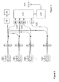
Figure 3 shows an example of the implementation of the central control node. This node carries out the spectral monitoring of the UWB signal by means of the analysis of the monitored radioelectric spectrum using a series of UWB sensors placed within its area of cover. - In order to carry out the following detailed description of the preferred embodiment of the present invention, permanent reference will be made to the Figures of the drawings, throughout which the same numerical references have been adopted for equal or similar parts. Thus, referring, in the first place, to
Figure 1 , the drawing shows the field of application of the method and device of cellular control of UWB transmitters/receptors. This diagram shows different UWB transmitters/receptors (1), or UWB receptors (2) only. These devices are operating within an area made up of the joint individual cover of a number of cells (3A) (3B) (3C) wherein UWB communications are established. Each cell can comprise a control node (4A) (4B) (4C) which facilitates communication between the UWB transmitters/receptors. Each UWB transmitter has allocated operating parameters (5) that can include the transmission power, the channel to use, among other characteristics and that can be assigned by the control node by means of a wireless communication. The UWB transmitters/receptors can move between different areas of cover carrying out what is known as roaming (6). In this case, each time the UWB terminal moves, for example from (3A) to (3B), a new allocation of operating parameters takes place. -
Figure 2 shows an example of the implementation of the UWB cellular control system for a single cell. In this figure it can be seen that the system comprises a central transmitting node (4A) which controls an area of cover (3A). The control bases information on the spectral and perhaps time content of the radioelectric environment (time-frequency analysis). The spectral information is obtained by means of a series of UWB sensors (7). These sensors capture the spectrum of the UWB signal and allocate the operating frequency and/or transmitted power, among other parameters, to each UWB transmitter within the area under cover with a view to optimising the spatial density, the spectral occupancy and guarantees the computability with other wireless transmission systems that operate within the band of frequencies of the UWB signal. The control information is transmitted to the UWB devices by the transmitter (4A). This information includes the operating parameters for each UWB device, which can include the channel to use, the level of power or the type of modulation, among others. -
Figure 3 shows an example of the implementation of the central control node in photonic technology. This node carries out the spectral monitoring of the UWB signal by means of a series of UWB sensors. This figure shows, without loss of generality, a particular implementation based on an analogue-digital converter complemented by a fibre optic connection of the different sensors with a central node where the UWB signals are digitalised with a view to carrying out an analysis in the full range of frequencies of the UWB signals. - A possible solution for the simultaneous spectral and time analysis of the UWB signals present within a certain area of cover, without prejudice to others, is the implementation of the example shown in
Figure 3 . This implementation is made up of a supercontinuum (8) type laser source. This laser source generates narrow optical pulses in time but with spectral components in a bandwidth that can reach hundreds of nanometres. The optical pulses generated by a supercontinuum laser source can be filtered in frequency (9) with a view to creating a series of channels by division in frequency, which is carried to each UWB sensor (7) by means of a stretch of fibre. In each sensor the UWB radio-frequency signal is modulated one ach optical channel and transmitted in fibre (11) to a central node for cellular control. Each sensor (7) comprises an electro-optical modulator (12) which modulates the UWB signal of radio-frequency, possibly amplified, captured by an antenna (13) on the corresponding optical channel. The modulated UWB signal is transmitted by fibre to a photodetector (14) where it is photodetected, digitalised (15) and processed (16) with a view to evaluating the joint spectral content of the signal captured by the sensors (7). - Based on the spectral content of the UWB signals in the cellular organisation the optimal operating parameters are calculated for each UWB transmitter with a view to optimising the communication capacities and avoiding the generation of signal levels that exceed the regulations applying to UWB technology. These parameters are transmitted to the UWB devices by means of a radiofrequency signal or signals (17).
- It is not considered necessary to make the content of this description more extensive for an expert in the art to understand its scope and the advantages resulting from the invention, as well as to develop and embody the object hereof.
- Nonetheless, it must be understood that the invention has been described according to a preferred embodiment thereof, meaning that it may be liable to changes without this entailing any alteration of its foundations, defined in the attached claims.
Claims (7)
- Cellular organisation of UWB transmitters/receptors that increases the efficiency of communication within a certain geographical area by means of the joint control of a grouping of cells in which UWB wireless communication technology is used.
- Method according to claim 1, wherein there is a central node that monitors the spectrum of the UWB signals transmitted in one or several cells by means of a series of sensors.
- Method according to claims 1 and 2, the central node evaluates the operating parameters - transmitted power, bandwidth or operating channel, among others - which maximise the spatial density and spectral use of the UWB devices within the area under cover.
- Method according to any of the preceding claims characterised in that the optimum operating parameters are calculated based on the monitoring of the radio-electric spectrum and transmitted to the UWB transmitters present in the area under cover.
- Method according to any of the preceding claims wherein roaming of a UWB transmitter/receptor is allowed between different areas of cover, carrying out an allocation of the most suitable operating parameters in each crossed area.
- Device for monitoring the radio-electric spectrum of UWB signals which comprises,
a series of sensors composed of an antenna and an electro-optical modulator among other elements,
an optical source that generates a series of optical channels, one per UWB sensor,
a series of optic fibres that carry the signal present in said channels to each one of the sensors of the system with a view to modulating the UWB signal over the optical channel,
a series of optic fibres that carry the optical signal with the modulated UWB signal thereon to a series of photodetectors that photodetect the signal,
a series of analogue-digital converters that digitalise the modulated signal received by the abovementioned optic fibres. - Method according to any of claims 1 and 2, whereby the UWB devices present in the area under cover are identified based on the analysis of the signals captured by the UWB sensors.
Applications Claiming Priority (2)
| Application Number | Priority Date | Filing Date | Title |
|---|---|---|---|
| ES200703431A ES2332559B2 (en) | 2007-12-11 | 2007-12-11 | METHOD AND PHOTONIC CELLULAR CONTROL DEVICE FOR ULTRA-WIDE BAND TRANSMITTERS / RECEIVERS (UWB). |
| PCT/ES2008/000772 WO2009074701A2 (en) | 2007-12-11 | 2008-12-10 | Photonic cell control device and method for ultra-wideband (uwb) transmitters/receivers |
Publications (3)
| Publication Number | Publication Date |
|---|---|
| EP2249597A2 true EP2249597A2 (en) | 2010-11-10 |
| EP2249597A4 EP2249597A4 (en) | 2015-12-09 |
| EP2249597B1 EP2249597B1 (en) | 2019-02-13 |
Family
ID=40755935
Family Applications (1)
| Application Number | Title | Priority Date | Filing Date |
|---|---|---|---|
| EP08858594.8A Not-in-force EP2249597B1 (en) | 2007-12-11 | 2008-12-10 | Photonic cell control device and method for ultra-wideband (uwb) transmitters/receivers |
Country Status (4)
| Country | Link |
|---|---|
| US (1) | US9048939B2 (en) |
| EP (1) | EP2249597B1 (en) |
| ES (1) | ES2332559B2 (en) |
| WO (1) | WO2009074701A2 (en) |
Families Citing this family (1)
| Publication number | Priority date | Publication date | Assignee | Title |
|---|---|---|---|---|
| US10153814B1 (en) * | 2017-06-13 | 2018-12-11 | Corning Incorporated | Massive multiple-input multiple-output (M-MIMO) wireless distribution system (WDS) and related methods for optimizing the M-MIMO WDS |
Family Cites Families (14)
| Publication number | Priority date | Publication date | Assignee | Title |
|---|---|---|---|---|
| US20040214568A1 (en) | 2002-03-27 | 2004-10-28 | Uraxs Communications, Inc. | Remote UltraWide Band communication system with short messaging and other functions |
| GB2399475B (en) | 2003-03-12 | 2005-06-29 | Roke Manor Research | Communication apparatus and method |
| KR100547880B1 (en) * | 2003-05-20 | 2006-01-31 | 삼성전자주식회사 | Indoor Short-range Communication Network System Using Ultra-Wideband Communication System |
| KR100539860B1 (en) * | 2003-06-09 | 2005-12-28 | 삼성전자주식회사 | Apparatus for transmitting signal between ultra wide band networks |
| KR100526550B1 (en) * | 2003-06-30 | 2005-11-03 | 삼성전자주식회사 | Access point for constructing an optical wireless network system based on optical fiber |
| KR100526552B1 (en) * | 2003-08-01 | 2005-11-03 | 삼성전자주식회사 | Wireless personal area network for extending service area |
| WO2005020508A1 (en) * | 2003-08-21 | 2005-03-03 | Koninklijke Philips Electronics N.V. | Wireless transmission control in uwb (ultra wide band) technology |
| US7046618B2 (en) * | 2003-11-25 | 2006-05-16 | Pulse-Link, Inc. | Bridged ultra-wideband communication method and apparatus |
| US7263333B2 (en) * | 2004-01-28 | 2007-08-28 | Harris Corporation | Wireless ultra wideband network having frequency bin transmission level setting and related methods |
| WO2005089304A2 (en) * | 2004-03-12 | 2005-09-29 | Conexant Systems, Inc. | Methods and systems for frequency shift keyed modulation for broadband wideband and ultra wideband communication |
| US20050232336A1 (en) * | 2004-04-20 | 2005-10-20 | Jaiganesh Balakrishnan | Versatile system for signal shaping in ultra-wideband communications |
| US7089033B2 (en) | 2004-05-17 | 2006-08-08 | Nokia Corporation | Mobile terminal having UWB and cellular capability |
| GB2429875B (en) * | 2005-09-05 | 2008-03-12 | Toshiba Res Europ Ltd | Improved broadband carrier frequency selection |
| US20070093237A1 (en) * | 2005-10-26 | 2007-04-26 | Research In Motion Limited | Locating and identifying a person using a mobile device |
-
2007
- 2007-12-11 ES ES200703431A patent/ES2332559B2/en active Active
-
2008
- 2008-12-10 EP EP08858594.8A patent/EP2249597B1/en not_active Not-in-force
- 2008-12-10 WO PCT/ES2008/000772 patent/WO2009074701A2/en not_active Ceased
- 2008-12-10 US US12/812,340 patent/US9048939B2/en not_active Expired - Fee Related
Non-Patent Citations (1)
| Title |
|---|
| See references of WO2009074701A2 * |
Also Published As
| Publication number | Publication date |
|---|---|
| ES2332559B2 (en) | 2010-06-23 |
| EP2249597A4 (en) | 2015-12-09 |
| ES2332559A1 (en) | 2010-02-08 |
| EP2249597B1 (en) | 2019-02-13 |
| US9048939B2 (en) | 2015-06-02 |
| WO2009074701A3 (en) | 2009-08-06 |
| US20110051788A1 (en) | 2011-03-03 |
| WO2009074701A2 (en) | 2009-06-18 |
Similar Documents
| Publication | Publication Date | Title |
|---|---|---|
| US6556551B1 (en) | Multi-frequency pilot beacon for CDMA systems | |
| EP1056226B1 (en) | Module for radio transmission over optical fibre | |
| CN106656827B (en) | LoRa base station router and narrow-band internet of things network system based on LoRa base station routing | |
| WO2004054280A3 (en) | Radio communication system employing spectral reuse transceivers | |
| CN101978719A (en) | System and method for utilizing spectral resources in wireless communications | |
| CN1500361A (en) | Dynamic Capacity Allocation of In-Building Systems | |
| Chakraborty et al. | Whisper: IoT in the TV white space spectrum | |
| CN110366114A (en) | A kind of localization method, positioning device, gateway and Network Management Equipment | |
| US20120165057A1 (en) | Radio base station, radio communication terminal, radio communication system, radio communication method and communication management method, using allocation of shared frequency | |
| US20150245354A1 (en) | Method and device for sending/receiving electromagnetic signals received/sent on one or more first frequency bands | |
| US9048939B2 (en) | Photonic cell control device and method for ultra-wideband (UWB)transmitters/receivers | |
| CN114039665A (en) | Multi-carrier frequency generation and reliable transmission method for RoF system | |
| US10541753B1 (en) | Direct optical to RF transceiver for a wireless system | |
| US20140233424A1 (en) | Mobile Backhaul Topology Planning and/or Optimization | |
| CN101667868A (en) | Two-way 40GHz millimeter wave RoF communication system integrating 802.11g standard OFDM chip and method therefor | |
| CN103209026A (en) | Full-duplex multi-service-convergence radio-over-fiber transmission system | |
| US9749051B2 (en) | Central office device, remote site device, and communication method thoseof | |
| Chen et al. | Versatile photonic-assisted cognitive radio regulatory system employing joint collaboration of multiple photonic integrated chips | |
| Kaur et al. | Cognitive radios: Need, capabilities, standards, applications and research challenges | |
| KR102950606B1 (en) | RF/DC Wireless Power based TVWS Communication Terminal Device and System | |
| US20230379983A1 (en) | Frequency Hopping Scheme For Improved Operation In Congested Environments | |
| CA2208968A1 (en) | Channel allocation method in connection with data transmissions in the optical frequency range | |
| CN101516143A (en) | System for simultaneous high-efficiency data down-conversion and data modulation using EAM modulator | |
| EP3076201A1 (en) | Optical communication and energy transmission from a base station controller to battery-less remote radio head (rrh) | |
| Tomkos et al. | The Future of Federated X-haul and Wireless Access in 6G Era |
Legal Events
| Date | Code | Title | Description |
|---|---|---|---|
| PUAI | Public reference made under article 153(3) epc to a published international application that has entered the european phase |
Free format text: ORIGINAL CODE: 0009012 |
|
| 17P | Request for examination filed |
Effective date: 20100811 |
|
| AK | Designated contracting states |
Kind code of ref document: A2 Designated state(s): AT BE BG CH CY CZ DE DK EE ES FI FR GB GR HR HU IE IS IT LI LT LU LV MC MT NL NO PL PT RO SE SI SK TR |
|
| AX | Request for extension of the european patent |
Extension state: AL BA MK RS |
|
| DAX | Request for extension of the european patent (deleted) | ||
| RIC1 | Information provided on ipc code assigned before grant |
Ipc: H04W 24/02 20090101AFI20150803BHEP Ipc: H04B 1/7163 20110101ALI20150803BHEP |
|
| A4 | Supplementary search report drawn up and despatched |
Effective date: 20151111 |
|
| RIC1 | Information provided on ipc code assigned before grant |
Ipc: H04B 1/7163 20110101ALI20151105BHEP Ipc: H04W 24/02 20090101AFI20151105BHEP |
|
| STAA | Information on the status of an ep patent application or granted ep patent |
Free format text: STATUS: EXAMINATION IS IN PROGRESS |
|
| 17Q | First examination report despatched |
Effective date: 20161223 |
|
| REG | Reference to a national code |
Ref country code: DE Ref legal event code: R079 Ref document number: 602008058999 Country of ref document: DE Free format text: PREVIOUS MAIN CLASS: H04W0024020000 Ipc: H04W0088080000 |
|
| GRAP | Despatch of communication of intention to grant a patent |
Free format text: ORIGINAL CODE: EPIDOSNIGR1 |
|
| STAA | Information on the status of an ep patent application or granted ep patent |
Free format text: STATUS: GRANT OF PATENT IS INTENDED |
|
| RIC1 | Information provided on ipc code assigned before grant |
Ipc: H04W 88/08 20090101AFI20180820BHEP Ipc: H04B 1/7163 20110101ALI20180820BHEP Ipc: H04B 1/719 20110101ALI20180820BHEP |
|
| INTG | Intention to grant announced |
Effective date: 20180925 |
|
| GRAS | Grant fee paid |
Free format text: ORIGINAL CODE: EPIDOSNIGR3 |
|
| GRAA | (expected) grant |
Free format text: ORIGINAL CODE: 0009210 |
|
| STAA | Information on the status of an ep patent application or granted ep patent |
Free format text: STATUS: THE PATENT HAS BEEN GRANTED |
|
| AK | Designated contracting states |
Kind code of ref document: B1 Designated state(s): AT BE BG CH CY CZ DE DK EE ES FI FR GB GR HR HU IE IS IT LI LT LU LV MC MT NL NO PL PT RO SE SI SK TR |
|
| REG | Reference to a national code |
Ref country code: GB Ref legal event code: FG4D |
|
| REG | Reference to a national code |
Ref country code: CH Ref legal event code: EP Ref country code: AT Ref legal event code: REF Ref document number: 1096975 Country of ref document: AT Kind code of ref document: T Effective date: 20190215 |
|
| REG | Reference to a national code |
Ref country code: IE Ref legal event code: FG4D |
|
| REG | Reference to a national code |
Ref country code: DE Ref legal event code: R096 Ref document number: 602008058999 Country of ref document: DE |
|
| REG | Reference to a national code |
Ref country code: LT Ref legal event code: MG4D |
|
| REG | Reference to a national code |
Ref country code: NL Ref legal event code: MP Effective date: 20190213 |
|
| PG25 | Lapsed in a contracting state [announced via postgrant information from national office to epo] |
Ref country code: SE Free format text: LAPSE BECAUSE OF FAILURE TO SUBMIT A TRANSLATION OF THE DESCRIPTION OR TO PAY THE FEE WITHIN THE PRESCRIBED TIME-LIMIT Effective date: 20190213 Ref country code: LT Free format text: LAPSE BECAUSE OF FAILURE TO SUBMIT A TRANSLATION OF THE DESCRIPTION OR TO PAY THE FEE WITHIN THE PRESCRIBED TIME-LIMIT Effective date: 20190213 Ref country code: NL Free format text: LAPSE BECAUSE OF FAILURE TO SUBMIT A TRANSLATION OF THE DESCRIPTION OR TO PAY THE FEE WITHIN THE PRESCRIBED TIME-LIMIT Effective date: 20190213 Ref country code: FI Free format text: LAPSE BECAUSE OF FAILURE TO SUBMIT A TRANSLATION OF THE DESCRIPTION OR TO PAY THE FEE WITHIN THE PRESCRIBED TIME-LIMIT Effective date: 20190213 Ref country code: NO Free format text: LAPSE BECAUSE OF FAILURE TO SUBMIT A TRANSLATION OF THE DESCRIPTION OR TO PAY THE FEE WITHIN THE PRESCRIBED TIME-LIMIT Effective date: 20190513 Ref country code: PT Free format text: LAPSE BECAUSE OF FAILURE TO SUBMIT A TRANSLATION OF THE DESCRIPTION OR TO PAY THE FEE WITHIN THE PRESCRIBED TIME-LIMIT Effective date: 20190613 |
|
| PG25 | Lapsed in a contracting state [announced via postgrant information from national office to epo] |
Ref country code: IS Free format text: LAPSE BECAUSE OF FAILURE TO SUBMIT A TRANSLATION OF THE DESCRIPTION OR TO PAY THE FEE WITHIN THE PRESCRIBED TIME-LIMIT Effective date: 20190613 Ref country code: GR Free format text: LAPSE BECAUSE OF FAILURE TO SUBMIT A TRANSLATION OF THE DESCRIPTION OR TO PAY THE FEE WITHIN THE PRESCRIBED TIME-LIMIT Effective date: 20190514 Ref country code: BG Free format text: LAPSE BECAUSE OF FAILURE TO SUBMIT A TRANSLATION OF THE DESCRIPTION OR TO PAY THE FEE WITHIN THE PRESCRIBED TIME-LIMIT Effective date: 20190513 Ref country code: LV Free format text: LAPSE BECAUSE OF FAILURE TO SUBMIT A TRANSLATION OF THE DESCRIPTION OR TO PAY THE FEE WITHIN THE PRESCRIBED TIME-LIMIT Effective date: 20190213 Ref country code: HR Free format text: LAPSE BECAUSE OF FAILURE TO SUBMIT A TRANSLATION OF THE DESCRIPTION OR TO PAY THE FEE WITHIN THE PRESCRIBED TIME-LIMIT Effective date: 20190213 |
|
| REG | Reference to a national code |
Ref country code: AT Ref legal event code: MK05 Ref document number: 1096975 Country of ref document: AT Kind code of ref document: T Effective date: 20190213 |
|
| PG25 | Lapsed in a contracting state [announced via postgrant information from national office to epo] |
Ref country code: RO Free format text: LAPSE BECAUSE OF FAILURE TO SUBMIT A TRANSLATION OF THE DESCRIPTION OR TO PAY THE FEE WITHIN THE PRESCRIBED TIME-LIMIT Effective date: 20190213 Ref country code: CZ Free format text: LAPSE BECAUSE OF FAILURE TO SUBMIT A TRANSLATION OF THE DESCRIPTION OR TO PAY THE FEE WITHIN THE PRESCRIBED TIME-LIMIT Effective date: 20190213 Ref country code: SK Free format text: LAPSE BECAUSE OF FAILURE TO SUBMIT A TRANSLATION OF THE DESCRIPTION OR TO PAY THE FEE WITHIN THE PRESCRIBED TIME-LIMIT Effective date: 20190213 Ref country code: ES Free format text: LAPSE BECAUSE OF FAILURE TO SUBMIT A TRANSLATION OF THE DESCRIPTION OR TO PAY THE FEE WITHIN THE PRESCRIBED TIME-LIMIT Effective date: 20190213 Ref country code: EE Free format text: LAPSE BECAUSE OF FAILURE TO SUBMIT A TRANSLATION OF THE DESCRIPTION OR TO PAY THE FEE WITHIN THE PRESCRIBED TIME-LIMIT Effective date: 20190213 Ref country code: DK Free format text: LAPSE BECAUSE OF FAILURE TO SUBMIT A TRANSLATION OF THE DESCRIPTION OR TO PAY THE FEE WITHIN THE PRESCRIBED TIME-LIMIT Effective date: 20190213 Ref country code: IT Free format text: LAPSE BECAUSE OF FAILURE TO SUBMIT A TRANSLATION OF THE DESCRIPTION OR TO PAY THE FEE WITHIN THE PRESCRIBED TIME-LIMIT Effective date: 20190213 |
|
| REG | Reference to a national code |
Ref country code: DE Ref legal event code: R097 Ref document number: 602008058999 Country of ref document: DE |
|
| PG25 | Lapsed in a contracting state [announced via postgrant information from national office to epo] |
Ref country code: PL Free format text: LAPSE BECAUSE OF FAILURE TO SUBMIT A TRANSLATION OF THE DESCRIPTION OR TO PAY THE FEE WITHIN THE PRESCRIBED TIME-LIMIT Effective date: 20190213 |
|
| PLBE | No opposition filed within time limit |
Free format text: ORIGINAL CODE: 0009261 |
|
| STAA | Information on the status of an ep patent application or granted ep patent |
Free format text: STATUS: NO OPPOSITION FILED WITHIN TIME LIMIT |
|
| PG25 | Lapsed in a contracting state [announced via postgrant information from national office to epo] |
Ref country code: AT Free format text: LAPSE BECAUSE OF FAILURE TO SUBMIT A TRANSLATION OF THE DESCRIPTION OR TO PAY THE FEE WITHIN THE PRESCRIBED TIME-LIMIT Effective date: 20190213 |
|
| 26N | No opposition filed |
Effective date: 20191114 |
|
| PG25 | Lapsed in a contracting state [announced via postgrant information from national office to epo] |
Ref country code: SI Free format text: LAPSE BECAUSE OF FAILURE TO SUBMIT A TRANSLATION OF THE DESCRIPTION OR TO PAY THE FEE WITHIN THE PRESCRIBED TIME-LIMIT Effective date: 20190213 |
|
| PG25 | Lapsed in a contracting state [announced via postgrant information from national office to epo] |
Ref country code: TR Free format text: LAPSE BECAUSE OF FAILURE TO SUBMIT A TRANSLATION OF THE DESCRIPTION OR TO PAY THE FEE WITHIN THE PRESCRIBED TIME-LIMIT Effective date: 20190213 |
|
| REG | Reference to a national code |
Ref country code: DE Ref legal event code: R119 Ref document number: 602008058999 Country of ref document: DE |
|
| REG | Reference to a national code |
Ref country code: CH Ref legal event code: PL |
|
| REG | Reference to a national code |
Ref country code: BE Ref legal event code: MM Effective date: 20191231 |
|
| PG25 | Lapsed in a contracting state [announced via postgrant information from national office to epo] |
Ref country code: MC Free format text: LAPSE BECAUSE OF FAILURE TO SUBMIT A TRANSLATION OF THE DESCRIPTION OR TO PAY THE FEE WITHIN THE PRESCRIBED TIME-LIMIT Effective date: 20190213 |
|
| GBPC | Gb: european patent ceased through non-payment of renewal fee |
Effective date: 20191210 |
|
| PG25 | Lapsed in a contracting state [announced via postgrant information from national office to epo] |
Ref country code: GB Free format text: LAPSE BECAUSE OF NON-PAYMENT OF DUE FEES Effective date: 20191210 Ref country code: DE Free format text: LAPSE BECAUSE OF NON-PAYMENT OF DUE FEES Effective date: 20200701 Ref country code: IE Free format text: LAPSE BECAUSE OF NON-PAYMENT OF DUE FEES Effective date: 20191210 Ref country code: FR Free format text: LAPSE BECAUSE OF NON-PAYMENT OF DUE FEES Effective date: 20191231 Ref country code: LU Free format text: LAPSE BECAUSE OF NON-PAYMENT OF DUE FEES Effective date: 20191210 |
|
| PG25 | Lapsed in a contracting state [announced via postgrant information from national office to epo] |
Ref country code: CH Free format text: LAPSE BECAUSE OF NON-PAYMENT OF DUE FEES Effective date: 20191231 Ref country code: LI Free format text: LAPSE BECAUSE OF NON-PAYMENT OF DUE FEES Effective date: 20191231 Ref country code: BE Free format text: LAPSE BECAUSE OF NON-PAYMENT OF DUE FEES Effective date: 20191231 |
|
| PG25 | Lapsed in a contracting state [announced via postgrant information from national office to epo] |
Ref country code: CY Free format text: LAPSE BECAUSE OF FAILURE TO SUBMIT A TRANSLATION OF THE DESCRIPTION OR TO PAY THE FEE WITHIN THE PRESCRIBED TIME-LIMIT Effective date: 20190213 |
|
| PG25 | Lapsed in a contracting state [announced via postgrant information from national office to epo] |
Ref country code: MT Free format text: LAPSE BECAUSE OF FAILURE TO SUBMIT A TRANSLATION OF THE DESCRIPTION OR TO PAY THE FEE WITHIN THE PRESCRIBED TIME-LIMIT Effective date: 20190213 Ref country code: HU Free format text: LAPSE BECAUSE OF FAILURE TO SUBMIT A TRANSLATION OF THE DESCRIPTION OR TO PAY THE FEE WITHIN THE PRESCRIBED TIME-LIMIT; INVALID AB INITIO Effective date: 20081210 |