EP2249594A1 - Estimation of the shadowing component in a wireless communication system - Google Patents
Estimation of the shadowing component in a wireless communication system Download PDFInfo
- Publication number
- EP2249594A1 EP2249594A1 EP09006174A EP09006174A EP2249594A1 EP 2249594 A1 EP2249594 A1 EP 2249594A1 EP 09006174 A EP09006174 A EP 09006174A EP 09006174 A EP09006174 A EP 09006174A EP 2249594 A1 EP2249594 A1 EP 2249594A1
- Authority
- EP
- European Patent Office
- Prior art keywords
- locations
- path loss
- location
- room
- path
- Prior art date
- Legal status (The legal status is an assumption and is not a legal conclusion. Google has not performed a legal analysis and makes no representation as to the accuracy of the status listed.)
- Granted
Links
- 238000004891 communication Methods 0.000 title claims abstract description 109
- 230000006854 communication Effects 0.000 title claims abstract description 109
- 238000005315 distribution function Methods 0.000 claims abstract description 50
- 230000005855 radiation Effects 0.000 claims abstract description 31
- 238000000034 method Methods 0.000 claims description 36
- 238000004088 simulation Methods 0.000 claims description 17
- 238000004590 computer program Methods 0.000 claims description 2
- 238000005259 measurement Methods 0.000 description 24
- 238000010586 diagram Methods 0.000 description 16
- 230000003287 optical effect Effects 0.000 description 10
- 238000013461 design Methods 0.000 description 8
- 230000006870 function Effects 0.000 description 8
- 238000004364 calculation method Methods 0.000 description 7
- 230000015572 biosynthetic process Effects 0.000 description 6
- 238000011161 development Methods 0.000 description 6
- 238000009826 distribution Methods 0.000 description 5
- 230000005540 biological transmission Effects 0.000 description 3
- 238000001514 detection method Methods 0.000 description 3
- 230000000694 effects Effects 0.000 description 3
- 238000013179 statistical model Methods 0.000 description 3
- 238000013459 approach Methods 0.000 description 2
- 230000009286 beneficial effect Effects 0.000 description 2
- 230000008901 benefit Effects 0.000 description 2
- 238000004422 calculation algorithm Methods 0.000 description 2
- 230000001413 cellular effect Effects 0.000 description 2
- 230000008859 change Effects 0.000 description 2
- 238000012512 characterization method Methods 0.000 description 2
- 230000001419 dependent effect Effects 0.000 description 2
- 230000001678 irradiating effect Effects 0.000 description 2
- 230000008569 process Effects 0.000 description 2
- 230000035945 sensitivity Effects 0.000 description 2
- 238000004458 analytical method Methods 0.000 description 1
- 230000002238 attenuated effect Effects 0.000 description 1
- 210000003850 cellular structure Anatomy 0.000 description 1
- 238000006073 displacement reaction Methods 0.000 description 1
- 238000000605 extraction Methods 0.000 description 1
- 238000005562 fading Methods 0.000 description 1
- 238000011835 investigation Methods 0.000 description 1
- 238000012417 linear regression Methods 0.000 description 1
- 230000001902 propagating effect Effects 0.000 description 1
- 230000009467 reduction Effects 0.000 description 1
Images




Classifications
-
- H—ELECTRICITY
- H04—ELECTRIC COMMUNICATION TECHNIQUE
- H04W—WIRELESS COMMUNICATION NETWORKS
- H04W16/00—Network planning, e.g. coverage or traffic planning tools; Network deployment, e.g. resource partitioning or cells structures
- H04W16/18—Network planning tools
- H04W16/20—Network planning tools for indoor coverage or short range network deployment
Definitions
- the invention relates to wireless communication systems.
- the invention relates to a method for estimation of a probability distribution function of shadowing in a wireless communication system, a program element for executing the method and a computer-readable medium storing the program element.
- a method for estimation of a probability distribution function of a shadowing in a wireless communication system comprises a room having a predefined geometry and a transmitter unit inside the room.
- the method comprises the steps of: selecting a path inside the room along which a receiver unit can be positioned; selecting a set of locations within a part of the room on the basis of the geometry of the room and the path; determining a path loss value for each location of the set of locations, wherein the path loss value describes the path loss of the radiation detected by the receiver unit at the location; calculating a two-dimensional result set comprising points having a first dimension and a second dimension, wherein the first dimension of a point is the special distance of a location of the set of locations to the transmitter unit and the second dimension is the path loss value at the respective location; selecting a mathematical (statistical) path loss model; calculating a mean value curve for the result set on the basis of the path loss model; calculating the probability distribution function from the result set, wherein
- a probability distribution function of a shadowing component in a, for example optical, wireless communication system For estimating or determining a probability distribution function of a shadowing component in a, for example optical, wireless communication system, only certain locations in the vicinity of a path are selected. The selection of the locations is further carried out on the basis of the geometry of the room in which the wireless communication system is situated.
- the path may represent the movement of a movable receiver unit detecting radiation emitted by a fixed transmitter unit. At the selected locations a path loss value of the radiation is determined. From the spatial distance of the locations and the respective path loss value at each location the probability distribution function is calculated.
- the shadowing estimation method may support the development of a statistical path loss model of an optical wireless communication system that may be arranged inside an aircraft cabin.
- the selected path loss model of a specific communication scenario (which may be defined by mutual orientation and properties of transmitters and receivers) may be completed.
- the path loss model may facilitate the calculation of the link budget, the design of the transmitter units and the receiver units, the design of a cellular system of the wireless communication system, the calculation of signal-to-interference ratio (SIR) maps, and the development of a handover algorithm.
- SIR signal-to-interference ratio
- the estimation of path loss may be a major component in the analysis and design of the link budget of a telecommunication system.
- the link budget may be the accounting of all the gains and losses from the transmitter unit through the medium to the receiver unit.
- Shadowing or path loss may be the loss or the fading of a signal emitted by a transmitter unit and detected by a receiver unit due to reflections on objects and shielding of objects, in particular borders of a room or a cavity comprised by the wireless communication system.
- Path loss or path attenuation may be the reduction in power density or attenuation of a wave propagating through space.
- a statistical model of the path loss as a function of the distance is provided.
- the statistical model may facilitate the design of the radiation and reception properties of transmitter units and receiver units.
- Such design properties may comprise, for example, the transmit power of light emitting diodes (LEDs) as transmitters of a transmitter unit, the number and/or formation of the LEDs in a transmitter unit, the sensitivity area of a photodiode (PD) and the number/formation of photodiodes as receivers of a receiver unit.
- the transmitter unit may be adapted to emit a radiation, wherein the room comprises borders which may be adapted to reflect the radiation, wherein the receiver unit may be adapted to detect the radiation emitted by the transmitter unit and reflected by the borders of the room.
- the transmitter unit may be positioned at a predefined position within the room and the room may comprise objects inside the room which define further borders of the room.
- the transmitter unit may be adapted to emit or send radiation with respect to a radiation characteristic.
- the power of the radiation emitted by a transmitter unit with homogeneous radiation characteristic is equal in each spatial direction.
- the power of radiation emitted in one direction may be higher than the power of radiation emitted in another direction.
- the receiver unit may be adapted to detect radiation with respect to a detection characteristic.
- the radiation falling onto a receiver unit with an inhomogeneous detection characteristic from one direction may result in a output from the receiver unit, which differs from the output of the receiver unit for radiation of the same power falling onto the receiver unit in a different direction.
- the path selected inside the room may represent positions of a receiver unit inside the room for a specific communication scenario for which the probability distribution function of the shadowing component has to be determined or estimated.
- the path may be a straight line.
- the estimation method may be used for consistently evaluating the shadowing effects in different communication scenarios. According to a communication scenario a path representing the communication scenario may be selected.
- the collected measurement values of path loss form a two-dimensional set.
- the first dimension of a point of the two-dimensional set is the distance from the transmitter unit and the second dimension of this point is the path loss value at the particular distance from the transmitter unit.
- a corresponding regression curve may be fitted through the scattered points of the two-dimensional result set, for example by a least square estimation.
- the regression curve represents a mean value curve.
- the borders of the room may comprise materials having certain reflection characteristics, and the shadowing component is estimated based on the reflection characteristics of the material.
- the calculation or estimating may be based on a diffuse scattering of rays emitted by the emitter unit, or may be based on a mirror like scattering with few diffuse scattered components.
- the wireless communication system may comprise a plurality of transmitter units and/or receiver units.
- selecting the set of locations comprises: selecting a set of spheres, each sphere having a predefined radius and centred at the transmitter unit; selecting locations on the spheres, thereby generating the set of locations.
- selecting the set of location comprises: selecting a number of circles, wherein each circle is orthogonal to a straight line from the centre of the circle to the transmitter unit; selecting locations on the circles, thereby generating the set of locations.
- locations By limiting locations to circles, the number of locations can be reduced, reducing a calculation or a measurement effort for the estimation method.
- the circles may be centred at the path.
- the circles may be centred at the orthogonal projection of the position of a transmitter unit onto a plane.
- Each circle may lie in this plane.
- the circles may be centred at the transmitter unit. Therefore, all locations on one circle may have the same spatial distance to the transmitter unit.
- selecting the set of locations comprises: selecting locations in the proximity of a border of the room.
- a location may lie in the proximity of a border of the room, if the minimal spatial distance of a location to the border is smaller than 5%, for example 1%, as the maximal diameter of the room.
- the probability is high that radiation reflected by the border may be detected.
- Selecting locations in the proximity of the border may have the advantage that mainly multiple reflected radiation counts for the estimation of the probability distribution function of the shadowing component. It may be important to collect location at which multiple reflections are detected, since the path loss values detected there contribute to the parts of the probability distribution function not containing the peak of the probability distribution function.
- selecting a set of location comprises: setting a field of view for each location, wherein the path loss value determined for a location describes the path loss of the radiation detected by the receiver unit at the location with respect to the field of view.
- any change in the azimuth, elevation and field of view properties of the transmitter unit and the receiver unit may influence the channel characteristics of the wireless communication system. Also for these cases, communication scenarios may be evaluated.
- the field of view at a location may be defined by inhomogeneous detecting characteristics or abilities of a receiver unit depending on the direction the radiation falls onto the receiver unit.
- the receiver unit may only detect the components of the irradiating rays falling within the field of view of the receiver unit.
- the field of view may also be defined by a cone looking in a certain direction with a certain aperture angle. The receiver unit then will detect all irradiating rays falling within the cone (or field of view) onto the receiver unit.
- the field of view for at least one location, most of the locations or each location is directed to the transmitter unit.
- the field of view of at least one location, most of the locations or each location is directed to a border of the room.
- a field of view on the basis of a plurality of directions may be possible.
- This kind of field of view may be defined by a plurality of cones, each cone lookin in one of the directions.
- the field of view of at least one location, most of the locations or each location is directed to multiple directions.
- Important communication scenarios may be a line-of-sight (LOS) communication scenario, a non-line-of-sight (NLOS) communication scenario with single reflections and a non-line-of-sight communication scenario with multiple reflections.
- LOS line-of-sight
- NLOS non-line-of-sight
- the communication scenario may be a line-of-sight communication scenario, wherein a straight line from each receiver unit on the path to the transmitter unit may not intersect with a border of the room.
- selecting the set of location comprises: selecting locations from circles centred at the path, wherein each circle is orthogonal to the straight line from the centre of the circle to the transmitter unit and the radius of the circle is determined such that the receiver locations are located in the proximity of the borders of the room, setting the field of view at each location in a direction to the transmitter unit.
- Measurement points may be selected from circles (or portions of the circles) orthogonal to and centred at the path.
- the displacement between two neighbouring circles in the direction of the path may determine the resolution of the estimation with respect to the spatial distance away from the transmitter unit.
- FOV field of view
- the points or locations on each circle may have a direct line of sight (LOS) to the transmitter unit.
- the radius of the circles may be chosen in order to collect the receiver locations that are closest or in the vicinity to the borders or objects in a neighbourhood to the path and which experience the highest shadowing.
- the neighbourhood of a path may be defined by the part of the room being contained in a volume, which is defined by all locations having a spatial distance from the path, which is smaller than a predetermined maximal distance.
- the predetermined maximal distance may be smaller than 20%, for example 10%, of the maximal diameter of the room.
- the communication scenario may be a single reflection non-line-of-sight communication scenario, wherein the path may lie in proximity to a border of the room, wherein a straight line of each point of the path to the transmitter unit may not intersect with a border of the room.
- selecting the set of locations comprises: selecting locations from circles, wherein each circle defines the basis of a cone with the apex of the cone at the transmitter unit and the basis being substantially parallel to a border of the room, setting the field of view at each receiver location in a direction to the border of the room.
- NLOS non-line-of-sight
- a path close to the reflecting object or border can be defined.
- the orientation of the field of view (FOV) of the measurement points or locations should be consistent with respect to the reflecting surface, border or object and the single reflection assumption.
- the direct special distance between the transmitter unit and the path defines the height of a family of geometrical cones.
- the basis of each cone and the path may lie in a plane, which may be substantially parallel to the border of the room.
- the measurement points or locations may be selected in this plane on circles or portions of circles, which are formed by the basis of each cone.
- each circle may be equidistant to the transmitter unit and may have nearly the same field of view (FOV) orientation with respect to the transmitter unit.
- the distance between the transmitter unit and the locations on each circle may be defined by the slant height of the respective cone.
- the communication scenario may be a multiple reflection non-line-of-sight communication scenario, wherein the path may have a neighbourhood with a plurality of borders (reflecting surfaces).
- selecting the set of locations comprises: selecting locations from spheres around the position of the transmitter unit, wherein the locations are located in the neighbourhood of the path, setting the field of view at each location to multiple directions, wherein each direction may be directed to a border of the plurality of borders.
- a linear path may be defined for which the shadowing can be estimated over the distance.
- the measurement points or locations may be selected on concentric spheres around the position of the transmitter unit. Furthermore, only the locations on the spheres may be counted which are located in a certain volume in the neighbourhood around the path.
- a multiple directions field of view (FOV) orientation may have to be considered in all path loss value measurements or determinations and further may have to fit the particular application and use case of the communication system.
- the path loss model may be a logarithmic distance path loss model.
- the mean value curve is determined on the basis of a linear fit of points of the result set or a linear fit through the selected path loss values with respect to the path loss model.
- the mean value curve may be the linear fit with respect to the logarithmic special distance.
- the distance function may be determined on the basis of a minimal distance of a point of the result set to the mean value curve.
- the distribution function of the shadowing in this case can be calculated from the set of the shortest distances between the measurement points and the mean fitted curve.
- the distance function may be determined in the following way: Each point of the result set has a path loss value and a spatial distance.
- the distance function may be the difference of the path loss value and the mean value at the spatial distance.
- determining the path loss value for each location comprises: virtually designing the wireless communication system; calculating the path loss values with a simulation.
- the simulation may be a ray-tracing simulation.
- the simulation may be a Monte Carlo ray-tracing simulation.
- virtually designing the wireless communication system comprises: virtually designing the room; virtually designing the transmitter unit; virtually designing the receiver unit.
- virtually designing the transmitter unit comprises virtually designing the radiation characteristics of the transmitter unit or the field of view of the transmitter unit.
- virtually designing the receiver unit comprises virtually designing the detection characteristic of the receiver unit or the field of view of the receiver unit.
- determining the path loss value for each location comprises: arranging the transmitter unit inside the room in a real-time measurement setup; measuring the path loss values with the receiver unit.
- the receiver unit may be transported to each location from the set of locations. The transporting and the measuring may be conducted by a robot.
- the wavelength of waves radiated or emitted by the transmitter unit may be small compared to the dimensions of the room.
- a wavelength may be small, if the wavelength is smaller than one million of the maximal diameter of the room.
- the wireless communication system may be an infrared communication system, wherein the transmitter unit comprises an infrared transmitter, for example LEDs, wherein the receiver unit comprises an infrared receiver, for example a photodiode.
- Infrared radiation may have a wavelength in the range of 1 ⁇ m.
- the wavelength of infrared radiation is small compared to the usual room of an office building or a cabin of a vehicle.
- the room may be a cabin of a vehicle, for example an aeroplane.
- the invention also relates to a computer-readable medium, in which a computer program for estimating a probability distribution function of the shadowing of a wireless communication system is stored, which, when being executed by a processor is adapted to carry out the method for estimating a probability distribution function.
- a computer-readable medium may be a floppy disk, a hard disk, an USB (Universal Serial Bus) storage device, a RAM (Read Access Memory), a ROM (read only memory) and an EPROM (Erasable Programmable Read Only Memory).
- a computer readable medium may also be a data communication network, e.g. the Internet, which allows downloading a program code.
- the invention further relates to a program element for estimating a probability distribution function of the shadowing of a wireless communication system, which, when being executed by a processor, is adapted to carry out the method for estimating a probability distribution function.
- Fig. 1 shows a flow diagram of an embodiment of a method for estimation a probability distribution function of a shadowing of an optical wireless communication system.
- a measurement setup for an optical wireless communication system is chosen.
- the optical wireless communication system may be an infrared optical wireless communication system.
- the measurement setup may be a simulation or a demonstrator. In the case of a simulation the room of the communication system has to be virtually designed. Further transmitter units and receiver units have to be virtually designed. In the case of a demonstrator, a real existing room like an aircraft cabin, can be used or has to be constructed.
- the locations of the transmitter units inside the room have to be chosen.
- a path representing a communication scenario has to be defined.
- the path may be the positions of a receiver unit of a mobile device carried by a person transversing the room.
- step S13 based on the geometry of the room and the path, a communication scenario has to be chosen.
- three shadowing estimation communication scenarios may be chosen, which facilitate the description of most of the communication scenarios that can appear in a measurement setup.
- a set of location is selected.
- step S14 a set of locations for a line-of-sight communication scenario are selected.
- step S16 a set of locations for a single reflection non-line-of-sight communication scenario is selected.
- step S18 a set of locations for a multiple reflections non-line-of-sight communication scenario are selected.
- At least two communication scenarios are selected. In this case at least two of the steps S14, S16 and S18 will be conducted.
- a path loss value for each location from the set of locations selected in at least one of the steps S14, S16 and S18 is determined. For example, this can be done by collecting measured path loss values in a real measurement setup or by calculating the path loss values by a ray-tracing simulation in a virtual measurement setup.
- step S22 a two-dimensional result set is created.
- the path loss values are plotted versus the distance of the respective location from the transmitter unit.
- step S24 a statistical path loss equation model is selected. On the basis of the path loss model a mean value curve for the result set is calculated. This may be done by calculating a regression, LSE of at least a part of the points of the result set.
- step S26 a probability distribution function is calculated from the result set. This may be done by calculating the probability distribution function from the shortest distances from the path loss values to the mean value curve.
- Fig. 2a shows a flow diagram of selecting locations for a line-of-sight communication scenario. The steps of Fig. 2a may be conducted in step S14 of Fig. 1 .
- step S140 locations or measurement points are selected from circles or portions of circles orthogonal to and centred on the path within the field of view of the transmitter unit.
- step S142 the radius of the circles is chosen so that these locations are collected, which are closest to the borders or objects in proximity to the path and which may experience the highest shadowing.
- step S144 the field of view at each location is set in direction to the transmitter.
- a receiver unit with a field of view in multiple directions may be located at each location with a predefined orientation. Then, only these locations on each circle are counted, which have a receiver unit with a field of view orientation or direction towards the transmitter unit. In this case, the field of view at the location is set to the field of view direction of the receiver unit located at the location looking in the direction to the transmitter unit.
- Fig. 2b shows a flow diagram for selecting a set of location in the case of a single reflection non-line-of-sight communication scenario. The steps of Fig. 2b may be conducted during step S16 of Fig. 1 .
- step S160 the family of cones defined by the direct distance between the transmitter unit and the path is identified. Further, the plane defined by the basis of each cone and the path is identified. The plane may be substantially parallel to a border of the room or an object inside the room.
- step S162 locations or measurement points are selected in this plane on circles or portions of the circles, which are formed by the basis of each cone.
- step S164 the field of view at each location is set in a direction towards the border.
- a receiver unit with a field of view in multiple directions may be located at each location with a predefined orientation. Then, only these locations on each circle are counted, which have a receiver unit with a field of view orientation or direction looking in the direction towards the reflecting border or object. In this case, the field of view at the location is set to the field of view direction of the receiver unit looking in the direction towards the reflecting border or object.
- Fig. 2c shows a flow diagram for selecting locations in the case of a multiple reflections non-line-of-sight communication scenario. The steps of Fig. 2c may be conducted during step S18 of Fig. 1 .
- step S180 the measurement points or locations are selected on concentric spheres around the position or location of the transmitter unit.
- step S182 only these locations on the spheres are counted, which are located in a certain volume in the neighbourhood around the path.
- step S184 the field of view at each location is set to multiple directions looking to the borders in the neighbourhood of the path.
- the field of view orientation of the measurement points or locations should be consistently considered on all circles and should fit the particular application and use case of the communication system and communication scenario.
- the method for estimating a probability distribution function of a shadowing of an optical wireless communication system is applied on the signal distribution of an infrared optical system for aircrafts.
- the signal distribution is simulated using a Monte Carlo ray-tracing simulation approach.
- Fig. 3 shows a receiver unit 10 in a schematic way.
- Each receiver 12 of the receiver unit has a field of view of 90°.
- PDs photo diodes
- the PDs are simulated by receiver points which are placed on the size of an infinitesimal cube at the point 13.
- the field of view of each receiver is represented by a cone 14 with an aperture angle of 90°. The basis of each cone forms the side of the cube.
- the direction D of the field of view 14 of each receiver 12 is orthogonal to the directions D of the field of views 14 of the other receivers 12.
- Fig. 4 shows a schematic view of a transmitter unit 20.
- the transmitter unit 20 consists of 16 transmitters 22, for example light emitting diodes (LEDs) 22, which are arranged around a circle 26, of for example 2cm diameter, centred at a point 24.
- Each transmitter 22 has a field of view of 20°, represented by a cone.
- the direction E of the field of view of the transmitters 22 of the transmitter unit 20 are all lying in a plane defined by the circle 26.
- the transmitter unit 20 has an omni-directional radiation characteristic in the plane and is designed to provide a high power multipath signal component.
- Fig. 5 shows a three-dimensional view of a virtually designed cabin 30 of an airplane.
- the cabin 30 has two corridors 32 and 34 with a height of 2,4 m.
- the cabin has a length of 7,6 m and is 6,6 m wide.
- the generalized model of the cabin 30 comprises a cuboid 36 which defines the main part of the cabin and two smaller cuboids 38 and 40 on top of the cuboid 36 which defines the upper part of the corridors 32 and 34.
- arrows are shown, defining the orientation of the cabin 30 with respect to the airplane.
- Arrow B is showing in the back direction of the airplane, arrow F in the front direction.
- Further arrow D shows in the down direction, arrow U in the up direction, arrow L in the left direction and arrow R in the right direction.
- a coordinate system is used with the origin at the point O.
- the arrows X, Z and Y define a coordinate system, wherein the arrow X is showing in the direction F, the arrow Z is showing in the direction U and the arrow Y is showing in the direction L, which are orthogonal to each other.
- Paths 31 a to 31 d are all straight lines parallel to the X direction, running from the front to the back of the airplane or the cabin.
- a communication system 35 may comprise the cabin 30 and at least one of the transmitters 33a, 33b and 33c. For each of the paths 31a to 31d only one of the transmitters 33a, 33b and 33c will be selected for the ray-tracing simulation. From a location of a transmitter unit 33a, 33b and 33c, rays will be traced to the respective receiver unit. Eventually, the rays have been reflected and have eventually thereby been attenuated by the borders of the cabin 30. The emitting power of the rays will depend on the emitting characteristics of the respective transmitter unit 33a, 33b and 33c.
- the transmitter units 33a, 33b and 33c may be designed like the transmitter unit shown in Fig. 4 .
- the receiver units of the array 40 may be designed like the receiver unit shown in Fig. 3 .
- receiver units are located by a receiver array 40.
- a receiver array 40 Inside the room 30, with the help of equidistantly separated irradiance observer planes a three-dimensional array of 200 x 200 x 100 receiver units is defined.
- the receiver units may be separated by each other by approximately 3 cm in horizontal and vertical directions. In Fig. 5 only a part of the cuboid array 40 of receivers is shown.
- the path loss values of each receiver unit of the array 40 may be calculated by ray-tracing. After that, the path loss values at the selected locations with the selected field of view may be used to calculate the probability distribution function. Alternatively, it is also possible to first select the locations and the field of view of the specific communication scenario and then calculate the path loss values with a simulation.
- Fig. 6 shows a cross-section through the cabin 30 orthogonal to the X-direction.
- the transmitters 33a, 33b and 33c are arranged below borders or ceilings 50, 52 and 54, respectively.
- the transmitter unit 33b is arranged in the middle of the cabin 30, the transmitters 33a and 33c are arranged at the sides of the cabin in the vicinity of the borders or sidewalls 56 and 58.
- the paths 31 a to 31 d have been chosen not to focus the simulation only on line -of-sight (LOS) rays emitted by the transmitters 33a to 33c, but also on non-line-of-sight (NLOS) rays for estimation of the probability distribution functions for each of the paths 31 a to 31d.
- LOS line -of-sight
- NLOS non-line-of-sight
- Path 31c represents a line-of-sight communication scenario which is enhanced by a single reflection component coming from the ceiling 52 in proximity.
- the transmitter unit 33b is used.
- the path 31 d represents a line-of-sight communication scenario which collects beside first reflections from the ceiling 54 further second single reflection components coming from the sidewall 56.
- the transmitter unit 33c is used for the calculation of the rays.
- the path 31 a represents a non-line-of-sight communication scenario due to azimuthal misalignment between the transmitter unit 33c and a receiver unit on the path 31 a.
- a receiver unit on the path 31 a further collects short range single reflections with multipath components coming from the sidewall 58 and single reflections coming from the ceiling 50.
- the transmitter 33a is used in the communication scenario for path 31 a only the transmitter 33a is used.
- the path 31 b represents a multiple reflections non-line-of-sight scenario, with reflections coming from the borders 60, 62 and 66 of the cabin 30.
- the borders 60, 62 and 64 limit the cuboid 38 in the left, the right and the up direction.
- a communication scenario associated with path 31 b allows for the investigation of path loss due to misalignment between transmitter and receiver in elevation, longer range multiple reflections and obstruction. In the communication scenario for path 31 b only the transmitter 33a is used.
- the statistical path loss PL at a distance d in metres is an average path loss at a distance d 0 plus the logarithm of the quotient of d with d 0 , multiplied by 10n , wherein n is the path loss exponent.
- d is the spatial distance between the transmitter unit and the receiver unit.
- the statistical path loss PL comprises an X ⁇ random variable representing the shadowing component.
- the shadowing component represented by the X ⁇ random variable is a Gaussian distribution around a linear regression mean curve over the logarithmic distance.
- the shadowing components and the probability distribution functions 71 c and 71 d along path 31 c and along path 31d, respectively, have been estimated according to the line-of-sight shadowing estimation communication scenario.
- Fig. 7a shows a two-dimensional result set 68c calculated from path loss values at locations in the vicinity of the path 31c. To obtain the result set 68c 12.546 points have been calculated. The field of view of each receiver unit at each location has been set to the backward direction. In the line-of-sight communication scenario associated with the path 31c, only the transmitter unit 33b has been used.
- the first dimension (abscissa) of the points of the result set 86c is the logarithmic distance from the transmitter unit 33b shown in Figs. 5 and 6 .
- the second dimensions (ordinate) of the points of the diagram are the path loss values in dB.
- point P has a logarithmic distance of about 0,75 and a path loss value of about 66 dB.
- the standard deviation of the points of the result set 68c is 0,56769.
- the mean value curve 69c represents the linear fit of the points of the result set 68c which has been calculated with respect to the points of the results set 68c between a linear distance from 1,2m to 5,6m.
- Fig. 7b shows a probability distribution function 71 c calculated from the result set 68c of Fig. 7a .
- the first dimension of the diagram is the deviation of the mean value path loss, the second dimension is the probability of the respective deviation.
- the probability distribution function 71c has not been normalized.
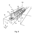
- Fig. 8 shows a three-dimensional view of a part of the room 30 containing the path 31d and the transmitter 33c. For selecting the locations for determining path loss values, circles 64 with a radius of 0,6 m around the path 31d have been chosen.
- the circles 64 are centred at the path 31d and are equidistant.
- the radius of the circles 64 has been chosen in order to collect the locations which are closest to the sidewall 56 and may experience the highest shadowing. For example, the locations 60 are in the vicinity of the sidewall 56. Only the signals arriving at the receivers in the direction "back" are counted.
- the field of view for calculating the path loss is set to the backward direction. For example, only the receiver 66 of the receiver unit 62 is used to determine the path loss value at the location 62.
- a line-of-sight signal component is received at distances from the transmitter unit 33a greater than 1 m.
- the first of the circles 64 has a distance from the receiver unit 33a about 1 m.
- Fig. 8 shows only some of the locations of the set of locations 65d selected in the vicinity of the path 31d.
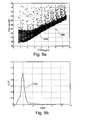
- Fig. 9a shows a two-dimensional result set 68d obtained for the path 31d.
- the diagram of Fig. 9 has the same dimensions like the diagram of Fig. 7a .
- the points of the result set 68d have a standard deviation of 0,81262.
- the linear fit or mean value curve 69d has been calculated from the points of the result set 68d with a linear distance between 1,2m and 5,6m. For calculating the result set 68d, 7.903 points have been determined.
- Fig. 9b shows the probability distribution function 71d calculated from the two-dimensional result set 68d shown in Fig. 9a . Again, the probability distribution function 71d has not been normalized.
- Fig. 10 shows a three-dimensional view of a part of the cabin 30 containing the path 31a and the transmitter unit 33a.
- the locations 72 for determining the path loss values are located on concentric circles 70, which are parallel to the sidewall 58.
- the concentric circles are centred around the projected position of the transmitter unit 33a onto the plane parallel to the sidewall 58 and containing the path 31 a.
- the field of view at each location 72 is directed to the sidewall 58. Only signals reflected by the sidewall 58 coming from the "right" direction are counted for calculating the path loss values.
- Fig. 10 shows only some of the locations of the set of locations 65a selected in the vicinity of the path 31 a.
- Fig. 11 a shows a two-dimensional result set 68a similar to those of Fig. 7a and Fig. 9a .
- the points of Fig. 11 a have a standard deviation of 1,2728.
- the linear fit or mean value curve 69a has been calculated from the points of the result set 68a with a linear distance between 0,4m and 5,61 m.
- Fig. 11b shows the probability distribution function 71 a calculated from the result set 68a.
- the diagram of Fig. 11b corresponds to the diagrams of Fig. 7b and Fig. 9b .
- Fig. 12a shows a two-dimensional result set 68b obtained for the path 31 b. Again, the diagram is similar to those of Fig. 7a , 9a and 11a . Shadowing components along path 31 b have been estimated according to the multiple reflections non-line of sight shadowing estimation communication scenario. Only the transmitter unit 33a has been used for the communication scenario. The locations for determining the path loss values are located on concentric spheres around the position of the transmitter unit 33a. Furthermore, only those locations on the spheres are counted, which are located in the small cuboid volume 38 in the neighbourhood of path 31 b. The field of view at each location is set to multiple directions "back", "front”, "left” and "right".
- the points in Fig. 12a have a standard deviation of 0,69539.
- the linear fit or mean value curve 89b in Fig. 12a has been calculated from the points of the result set 68b with a linear distance between 1,45m to 5,78m.
- Fig. 12b similar to Figs. 7b , 9b and 11b , shows the probability distribution function 71 b calculated from the two-dimensional result set 68b.
- Fig. 13 shows an airplane 100 of a cabin 30 with a wireless communication system 35 for which the previously described communication scenarios have been estimated.
- the cabin 30 may have nearly the geometry as shown in Fig. 5 .
- the method allows to present a graphical representation of a probability distribution function that describes the shadowing random process.
- measurement sets of path loss values determine the path loss scatterings in different communication scenarios.
- the needed probability distribution function is calculated for the particular path loss scattering.
- the presented method describes a proper and consistent way to select the locations of the path loss measurement points in the geometry of the setup in line of sight (LOS) and non-line-of-sight (NLOS) scenarios.
- the measurements can be either conducted by a simulation (Monte Carlo ray-tracing irradiation simulation) or by measurements with the optical communication hardware (transmitter device and receiver device).
- the obtained probability distribution function and the path loss model derived therewith may facilitate the design of the radiation and reception properties of the transmitter units and receiver units.
- the LED transmit power and the number and formation of LEDs in a transmitter unit, the photodiode sensitivity area and the number and formation of photodiodes in a receiver unit and the link budget may be optimized.
- the design of the cellular structure and frequency reuse factor may be optimized, the signal-to-interference ratio (SIR) distribution (maps) in the communication network may be calculated, and the development of handover algorithms may be facilitated.
- SIR signal-to-interference ratio
Landscapes
- Engineering & Computer Science (AREA)
- Computer Networks & Wireless Communication (AREA)
- Signal Processing (AREA)
- Optical Communication System (AREA)
- Mobile Radio Communication Systems (AREA)
Abstract
Description
- The invention relates to wireless communication systems. In particular, the invention relates to a method for estimation of a probability distribution function of shadowing in a wireless communication system, a program element for executing the method and a computer-readable medium storing the program element.
- The development of a wireless system requires thorough understanding and characterization of the propagation environment. Of high importance is a statistical model of the path loss as a function of the distance between a receiver unit and a transmitter unit in the wireless system. Such a model facilitates the design of the radiation and the reception properties of the transmitter units and receiver units, the transmit power, the number and/or formation of single transmitters in a transmitter unit and the number and/or formation of single receivers in a receiver unit.
- It is an object of the invention to provide characterizations of the propagation environment of a wireless communication system inside a room.
- According to an embodiment of the invention, a method for estimation of a probability distribution function of a shadowing in a wireless communication system is provided. The wireless communication system comprises a room having a predefined geometry and a transmitter unit inside the room. The method comprises the steps of: selecting a path inside the room along which a receiver unit can be positioned; selecting a set of locations within a part of the room on the basis of the geometry of the room and the path; determining a path loss value for each location of the set of locations, wherein the path loss value describes the path loss of the radiation detected by the receiver unit at the location; calculating a two-dimensional result set comprising points having a first dimension and a second dimension, wherein the first dimension of a point is the special distance of a location of the set of locations to the transmitter unit and the second dimension is the path loss value at the respective location; selecting a mathematical (statistical) path loss model; calculating a mean value curve for the result set on the basis of the path loss model; calculating the probability distribution function from the result set, wherein a distance of a point of the result set to a mean value of the mean value curve is determined by a distance function.
- For estimating or determining a probability distribution function of a shadowing component in a, for example optical, wireless communication system, only certain locations in the vicinity of a path are selected. The selection of the locations is further carried out on the basis of the geometry of the room in which the wireless communication system is situated. The path may represent the movement of a movable receiver unit detecting radiation emitted by a fixed transmitter unit. At the selected locations a path loss value of the radiation is determined. From the spatial distance of the locations and the respective path loss value at each location the probability distribution function is calculated.
- In particular, the shadowing estimation method may support the development of a statistical path loss model of an optical wireless communication system that may be arranged inside an aircraft cabin.
- Having established the probability distribution function of the shadowing component, the selected path loss model of a specific communication scenario (which may be defined by mutual orientation and properties of transmitters and receivers) may be completed. The path loss model may facilitate the calculation of the link budget, the design of the transmitter units and the receiver units, the design of a cellular system of the wireless communication system, the calculation of signal-to-interference ratio (SIR) maps, and the development of a handover algorithm.
- The estimation of path loss may be a major component in the analysis and design of the link budget of a telecommunication system. The link budget may be the accounting of all the gains and losses from the transmitter unit through the medium to the receiver unit.
- Shadowing or path loss may be the loss or the fading of a signal emitted by a transmitter unit and detected by a receiver unit due to reflections on objects and shielding of objects, in particular borders of a room or a cavity comprised by the wireless communication system. Path loss or path attenuation may be the reduction in power density or attenuation of a wave propagating through space.
- With the method for estimation of a probability distribution function of a shadowing component in a wireless communication system, a statistical model of the path loss as a function of the distance is provided. With this, the development of a wireless communication system, in particular a cellular infrared wireless system for an aircraft, may be facilitated. In particular, the statistical model may facilitate the design of the radiation and reception properties of transmitter units and receiver units. Such design properties may comprise, for example, the transmit power of light emitting diodes (LEDs) as transmitters of a transmitter unit, the number and/or formation of the LEDs in a transmitter unit, the sensitivity area of a photodiode (PD) and the number/formation of photodiodes as receivers of a receiver unit.
- The transmitter unit may be adapted to emit a radiation, wherein the room comprises borders which may be adapted to reflect the radiation, wherein the receiver unit may be adapted to detect the radiation emitted by the transmitter unit and reflected by the borders of the room.
- The transmitter unit may be positioned at a predefined position within the room and the room may comprise objects inside the room which define further borders of the room.
- The transmitter unit may be adapted to emit or send radiation with respect to a radiation characteristic. The power of the radiation emitted by a transmitter unit with homogeneous radiation characteristic is equal in each spatial direction. For a transmitter unit with an inhomogeneous radiation characteristic, the power of radiation emitted in one direction may be higher than the power of radiation emitted in another direction.
- Also, the receiver unit may be adapted to detect radiation with respect to a detection characteristic. The radiation falling onto a receiver unit with an inhomogeneous detection characteristic from one direction may result in a output from the receiver unit, which differs from the output of the receiver unit for radiation of the same power falling onto the receiver unit in a different direction.
- Since any change in the predefined geometry of a room, the position and the orientation of the transmitter unit and the position and orientation of the receiver unit influences the path loss of the receiver unit with respect to the transmitter unit, plurality of communication scenarios may be possible inside a room. The path selected inside the room may represent positions of a receiver unit inside the room for a specific communication scenario for which the probability distribution function of the shadowing component has to be determined or estimated. The path may be a straight line.
- The estimation method may be used for consistently evaluating the shadowing effects in different communication scenarios. According to a communication scenario a path representing the communication scenario may be selected.
- The collected measurement values of path loss form a two-dimensional set. The first dimension of a point of the two-dimensional set is the distance from the transmitter unit and the second dimension of this point is the path loss value at the particular distance from the transmitter unit. Depending on the assumed mathematical path loss model, a corresponding regression curve may be fitted through the scattered points of the two-dimensional result set, for example by a least square estimation. The regression curve represents a mean value curve.
- To reduce the calculation effort, it may be beneficial to restrict the set of locations to certain areas, volumes, ranges or parts of the room. In this way, the number of locations may be reduced. Further, in order to improve the estimation of the probability distribution function of the shadowing component, it may be beneficial to restrict the locations of the set of locations to more concrete areas, volumes, ranges or parts of the room. In this way, mainly locations strongly influencing the shape of the probability distribution function are counted. In the following embodiments restricting the set of locations are presented.
- According to an embodiment of the invention, the borders of the room may comprise materials having certain reflection characteristics, and the shadowing component is estimated based on the reflection characteristics of the material. The calculation or estimating may be based on a diffuse scattering of rays emitted by the emitter unit, or may be based on a mirror like scattering with few diffuse scattered components.
- According to an embodiment of the invention, the wireless communication system may comprise a plurality of transmitter units and/or receiver units.
- According to an embodiment of the invention, selecting the set of locations comprises: selecting a set of spheres, each sphere having a predefined radius and centred at the transmitter unit; selecting locations on the spheres, thereby generating the set of locations. By limiting the locations to spheres centred to the transmitter unit, only locations with predefined distance to the transmitter unit are selected, thereby reducing the number of locations for which the path loss value has to be measured or calculated.
- According to an embodiment of the invention, selecting the set of location comprises: selecting a number of circles, wherein each circle is orthogonal to a straight line from the centre of the circle to the transmitter unit; selecting locations on the circles, thereby generating the set of locations. By limiting locations to circles, the number of locations can be reduced, reducing a calculation or a measurement effort for the estimation method.
- According to an embodiment of the invention, the circles may be centred at the path. According to an embodiment of the invention, the circles may be centred at the orthogonal projection of the position of a transmitter unit onto a plane. Each circle may lie in this plane. According to an embodiment of the invention, the circles may be centred at the transmitter unit. Therefore, all locations on one circle may have the same spatial distance to the transmitter unit.
- According to an embodiment of the invention, selecting the set of locations comprises: selecting locations in the proximity of a border of the room. A location may lie in the proximity of a border of the room, if the minimal spatial distance of a location to the border is smaller than 5%, for example 1%, as the maximal diameter of the room. In the proximity of a border of the room, the probability is high that radiation reflected by the border may be detected. Selecting locations in the proximity of the border may have the advantage that mainly multiple reflected radiation counts for the estimation of the probability distribution function of the shadowing component. It may be important to collect location at which multiple reflections are detected, since the path loss values detected there contribute to the parts of the probability distribution function not containing the peak of the probability distribution function.
- According to an embodiment of the invention, selecting a set of location comprises: setting a field of view for each location, wherein the path loss value determined for a location describes the path loss of the radiation detected by the receiver unit at the location with respect to the field of view.
- Any change in the azimuth, elevation and field of view properties of the transmitter unit and the receiver unit may influence the channel characteristics of the wireless communication system. Also for these cases, communication scenarios may be evaluated.
- The field of view at a location may be defined by inhomogeneous detecting characteristics or abilities of a receiver unit depending on the direction the radiation falls onto the receiver unit. The receiver unit may only detect the components of the irradiating rays falling within the field of view of the receiver unit. The field of view may also be defined by a cone looking in a certain direction with a certain aperture angle. The receiver unit then will detect all irradiating rays falling within the cone (or field of view) onto the receiver unit.
- According to embodiments of the invention, the field of view for at least one location, most of the locations or each location is directed to the transmitter unit.
- According to embodiments of the invention, the field of view of at least one location, most of the locations or each location is directed to a border of the room.
- Also a field of view on the basis of a plurality of directions may be possible. This kind of field of view may be defined by a plurality of cones, each cone lookin in one of the directions.
- According to embodiments of the inventions, the field of view of at least one location, most of the locations or each location is directed to multiple directions.
- Important communication scenarios may be a line-of-sight (LOS) communication scenario, a non-line-of-sight (NLOS) communication scenario with single reflections and a non-line-of-sight communication scenario with multiple reflections.
- According to an embodiment of the invention, the communication scenario may be a line-of-sight communication scenario, wherein a straight line from each receiver unit on the path to the transmitter unit may not intersect with a border of the room.
- According to an embodiment of the invention, in a line-of-sight communication scenario, selecting the set of location comprises: selecting locations from circles centred at the path, wherein each circle is orthogonal to the straight line from the centre of the circle to the transmitter unit and the radius of the circle is determined such that the receiver locations are located in the proximity of the borders of the room, setting the field of view at each location in a direction to the transmitter unit.
- Given a line-of-sight (LOS) transmission, there may be a direct path between the transmitter unit and the receiver unit. The variations of the path loss in the neighbourhood of the path define the shadowing process. To extract or estimate these variations, the following approach is proposed. Measurement points may be selected from circles (or portions of the circles) orthogonal to and centred at the path. The displacement between two neighbouring circles in the direction of the path may determine the resolution of the estimation with respect to the spatial distance away from the transmitter unit. Furthermore, only these points from the circles may be considered, which fall within the field of view (FOV) of the transmitter unit. The points or locations on each circle may have a direct line of sight (LOS) to the transmitter unit. The radius of the circles may be chosen in order to collect the receiver locations that are closest or in the vicinity to the borders or objects in a neighbourhood to the path and which experience the highest shadowing.
- The neighbourhood of a path may be defined by the part of the room being contained in a volume, which is defined by all locations having a spatial distance from the path, which is smaller than a predetermined maximal distance. The predetermined maximal distance may be smaller than 20%, for example 10%, of the maximal diameter of the room.
- According to an embodiment of the invention, the communication scenario may be a single reflection non-line-of-sight communication scenario, wherein the path may lie in proximity to a border of the room, wherein a straight line of each point of the path to the transmitter unit may not intersect with a border of the room. According to an embodiment of the invention, in a single reflection non-line-of-sight communication scenario, selecting the set of locations comprises: selecting locations from circles, wherein each circle defines the basis of a cone with the apex of the cone at the transmitter unit and the basis being substantially parallel to a border of the room, setting the field of view at each receiver location in a direction to the border of the room.
- Given a single reflection non-line-of-sight (NLOS) transmission, which means that there is no direct path for rays between the transmitter unit and the receiver unit, a path close to the reflecting object or border can be defined. The orientation of the field of view (FOV) of the measurement points or locations should be consistent with respect to the reflecting surface, border or object and the single reflection assumption. The direct special distance between the transmitter unit and the path defines the height of a family of geometrical cones. The basis of each cone and the path may lie in a plane, which may be substantially parallel to the border of the room. The measurement points or locations may be selected in this plane on circles or portions of circles, which are formed by the basis of each cone. The locations on each circle may be equidistant to the transmitter unit and may have nearly the same field of view (FOV) orientation with respect to the transmitter unit. The distance between the transmitter unit and the locations on each circle may be defined by the slant height of the respective cone.
- According to an embodiment of the invention, the communication scenario may be a multiple reflection non-line-of-sight communication scenario, wherein the path may have a neighbourhood with a plurality of borders (reflecting surfaces).
- According to an embodiment of the invention, in a multiple reflection non-line-of-sight communication scenario, selecting the set of locations comprises: selecting locations from spheres around the position of the transmitter unit, wherein the locations are located in the neighbourhood of the path, setting the field of view at each location to multiple directions, wherein each direction may be directed to a border of the plurality of borders.
- Given a multiple reflection non-line-of-sight (NLOS) transmission, a linear path may be defined for which the shadowing can be estimated over the distance. In this case, the measurement points or locations may be selected on concentric spheres around the position of the transmitter unit. Furthermore, only the locations on the spheres may be counted which are located in a certain volume in the neighbourhood around the path. Because of the non-line-of-sight (NLOS) multipath nature of the communication scenario, a multiple directions field of view (FOV) orientation may have to be considered in all path loss value measurements or determinations and further may have to fit the particular application and use case of the communication system.
- According to an embodiment of the invention, the path loss model may be a logarithmic distance path loss model.
- According to an embodiment of the invention, the mean value curve is determined on the basis of a linear fit of points of the result set or a linear fit through the selected path loss values with respect to the path loss model. For example, for the logarithmic distance path loss model, the mean value curve may be the linear fit with respect to the logarithmic special distance.
- According to an embodiment of the invention, the distance function may be determined on the basis of a minimal distance of a point of the result set to the mean value curve. The distribution function of the shadowing in this case can be calculated from the set of the shortest distances between the measurement points and the mean fitted curve.
- Alternatively or additionally, the distance function may be determined in the following way: Each point of the result set has a path loss value and a spatial distance. The distance function may be the difference of the path loss value and the mean value at the spatial distance.
- According to an embodiment of the invention, determining the path loss value for each location comprises: virtually designing the wireless communication system; calculating the path loss values with a simulation. The simulation may be a ray-tracing simulation. In particular, the simulation may be a Monte Carlo ray-tracing simulation.
- According to an embodiment of the invention, virtually designing the wireless communication system comprises: virtually designing the room; virtually designing the transmitter unit; virtually designing the receiver unit.
- According to an embodiment of the invention, virtually designing the transmitter unit comprises virtually designing the radiation characteristics of the transmitter unit or the field of view of the transmitter unit.
- According to an embodiment of the invention, virtually designing the receiver unit comprises virtually designing the detection characteristic of the receiver unit or the field of view of the receiver unit.
- According to an embodiment of the invention, determining the path loss value for each location comprises: arranging the transmitter unit inside the room in a real-time measurement setup; measuring the path loss values with the receiver unit. The receiver unit may be transported to each location from the set of locations. The transporting and the measuring may be conducted by a robot.
- According to an embodiment of the invention, the wavelength of waves radiated or emitted by the transmitter unit may be small compared to the dimensions of the room. A wavelength may be small, if the wavelength is smaller than one million of the maximal diameter of the room.
- According to an embodiment of the invention, the wireless communication system may be an infrared communication system, wherein the transmitter unit comprises an infrared transmitter, for example LEDs, wherein the receiver unit comprises an infrared receiver, for example a photodiode.
- Infrared radiation may have a wavelength in the range of 1 µm. The wavelength of infrared radiation is small compared to the usual room of an office building or a cabin of a vehicle.
- According to an embodiment of the invention, the room may be a cabin of a vehicle, for example an aeroplane.
- The invention also relates to a computer-readable medium, in which a computer program for estimating a probability distribution function of the shadowing of a wireless communication system is stored, which, when being executed by a processor is adapted to carry out the method for estimating a probability distribution function.
- A computer-readable medium may be a floppy disk, a hard disk, an USB (Universal Serial Bus) storage device, a RAM (Read Access Memory), a ROM (read only memory) and an EPROM (Erasable Programmable Read Only Memory). A computer readable medium may also be a data communication network, e.g. the Internet, which allows downloading a program code.
- The invention further relates to a program element for estimating a probability distribution function of the shadowing of a wireless communication system, which, when being executed by a processor, is adapted to carry out the method for estimating a probability distribution function.
- These and other aspects of the invention will be apparent from and elucidated with reference to the embodiments described hereinafter.
- Below, embodiments of the present invention are described in more detail with reference to the attached drawings.
- Fig. 1
- shows a flow diagram of a method for estimation of a probability distri- bution function according to an embodiment of the invention.
- Fig. 2a
- shows a flow diagram for selecting a set of locations for a line-of-sight communication scenario according to an embodiment of the invention.
- Fig. 2b
- shows a flow diagram for selecting a set of locations for a single reflec- tion non-line-of-sight communication scenario according to an embodi- ment of the invention.
- Fig. 2c
- shows a flow diagram for selecting a set of locations for a multiple re- flection non-line-of-sight communication scenario according to an em- bodiment of the invention.
- Fig. 3
- shows a schematic three-dimensional view of a receiver unit.
- Fig. 4
- shows a schematic three-dimensional view of a transmitter unit.
- Fig. 5
- shows a three-dimensional view of a virtually designed aircraft cabin.
- Fig. 6
- shows a cross-section through the virtually designed aircraft cabin of
Fig. 5 . - Fig. 7a
- shows a two-dimensional result set for a communication scenario.
- Fig. 7b
- shows probability distribution function obtained from the result set of
Fig. 7a . - Fig. 8
- shows a three-dimensional view of a part of the room shown in
Fig. 5 . - Fig. 9a
- shows a two-dimensional result set obtained for a further communica- tion scenario.
- Fig. 9b
- shows a probability distribution function obtained from the result set of
Fig. 9a . - Fig. 10
- shows a three-dimensional view of a part of the room shown in
Fig. 5 . - Fig. 11a
- shows a two-dimensional result set obtained for a further communica- tion scenario.
- Fig. 11b
- shows a probability distribution function obtained from the result set of
Fig. 11a . - Fig. 12a
- shows a two-dimensional result set obtained for a further communica- tion scenario.
- Fig. 12b
- shows a probability distribution function obtained from the result set of
Fig. 12a . - Fig. 13
- shows an airplane with a cabin containing a wireless communication system.
-
Fig. 1 shows a flow diagram of an embodiment of a method for estimation a probability distribution function of a shadowing of an optical wireless communication system. - In step S10, a measurement setup for an optical wireless communication system is chosen. The optical wireless communication system may be an infrared optical wireless communication system. The measurement setup may be a simulation or a demonstrator. In the case of a simulation the room of the communication system has to be virtually designed. Further transmitter units and receiver units have to be virtually designed. In the case of a demonstrator, a real existing room like an aircraft cabin, can be used or has to be constructed.
- Further, the locations of the transmitter units inside the room have to be chosen.
- In step S12, a path representing a communication scenario has to be defined. The path may be the positions of a receiver unit of a mobile device carried by a person transversing the room.
- In step S13, based on the geometry of the room and the path, a communication scenario has to be chosen. In the present embodiment of the estimation method, three shadowing estimation communication scenarios may be chosen, which facilitate the description of most of the communication scenarios that can appear in a measurement setup.
- Dependent on the chosen communication setup, a set of location is selected.
- In step S14, a set of locations for a line-of-sight communication scenario are selected.
- In step S16, a set of locations for a single reflection non-line-of-sight communication scenario is selected.
- In step S18, a set of locations for a multiple reflections non-line-of-sight communication scenario are selected.
- It is also possible, that at least two communication scenarios are selected. In this case at least two of the steps S14, S16 and S18 will be conducted.
- In step S20, a path loss value for each location from the set of locations selected in at least one of the steps S14, S16 and S18 is determined. For example, this can be done by collecting measured path loss values in a real measurement setup or by calculating the path loss values by a ray-tracing simulation in a virtual measurement setup.
- In step S22, a two-dimensional result set is created. In the result set, the path loss values are plotted versus the distance of the respective location from the transmitter unit.
- In step S24, a statistical path loss equation model is selected. On the basis of the path loss model a mean value curve for the result set is calculated. This may be done by calculating a regression, LSE of at least a part of the points of the result set.
- In step S26, a probability distribution function is calculated from the result set. This may be done by calculating the probability distribution function from the shortest distances from the path loss values to the mean value curve.
-
Fig. 2a shows a flow diagram of selecting locations for a line-of-sight communication scenario. The steps ofFig. 2a may be conducted in step S14 ofFig. 1 . - In step S140, locations or measurement points are selected from circles or portions of circles orthogonal to and centred on the path within the field of view of the transmitter unit.
- In step S142, the radius of the circles is chosen so that these locations are collected, which are closest to the borders or objects in proximity to the path and which may experience the highest shadowing.
- In step S144, the field of view at each location is set in direction to the transmitter. Alternatively, a receiver unit with a field of view in multiple directions may be located at each location with a predefined orientation. Then, only these locations on each circle are counted, which have a receiver unit with a field of view orientation or direction towards the transmitter unit. In this case, the field of view at the location is set to the field of view direction of the receiver unit located at the location looking in the direction to the transmitter unit.
-
Fig. 2b shows a flow diagram for selecting a set of location in the case of a single reflection non-line-of-sight communication scenario. The steps ofFig. 2b may be conducted during step S16 ofFig. 1 . - In step S160, the family of cones defined by the direct distance between the transmitter unit and the path is identified. Further, the plane defined by the basis of each cone and the path is identified. The plane may be substantially parallel to a border of the room or an object inside the room.
- In step S162, locations or measurement points are selected in this plane on circles or portions of the circles, which are formed by the basis of each cone.
- In step S164, the field of view at each location is set in a direction towards the border. Alternatively, a receiver unit with a field of view in multiple directions may be located at each location with a predefined orientation. Then, only these locations on each circle are counted, which have a receiver unit with a field of view orientation or direction looking in the direction towards the reflecting border or object. In this case, the field of view at the location is set to the field of view direction of the receiver unit looking in the direction towards the reflecting border or object.
-
Fig. 2c shows a flow diagram for selecting locations in the case of a multiple reflections non-line-of-sight communication scenario. The steps ofFig. 2c may be conducted during step S18 ofFig. 1 . - In step S180 the measurement points or locations are selected on concentric spheres around the position or location of the transmitter unit.
- In step S182 only these locations on the spheres are counted, which are located in a certain volume in the neighbourhood around the path.
- In step S184 the field of view at each location is set to multiple directions looking to the borders in the neighbourhood of the path. The field of view orientation of the measurement points or locations should be consistently considered on all circles and should fit the particular application and use case of the communication system and communication scenario.
- In the following, the method for estimating a probability distribution function of a shadowing of an optical wireless communication system is applied on the signal distribution of an infrared optical system for aircrafts. The signal distribution is simulated using a Monte Carlo ray-tracing simulation approach.
-
Fig. 3 shows areceiver unit 10 in a schematic way. Eachreceiver 12 of the receiver unit has a field of view of 90°. For example, six photo diodes (PDs) 12 are placed on the sides of a cube to form areceiver unit 10. If thereceiver unit 10 is virtually designed, the PDs are simulated by receiver points which are placed on the size of an infinitesimal cube at thepoint 13. InFig. 10 the field of view of each receiver is represented by acone 14 with an aperture angle of 90°. The basis of each cone forms the side of the cube. The direction D of the field ofview 14 of eachreceiver 12 is orthogonal to the directions D of the field ofviews 14 of theother receivers 12. -
Fig. 4 shows a schematic view of atransmitter unit 20. Thetransmitter unit 20 consists of 16transmitters 22, for example light emitting diodes (LEDs) 22, which are arranged around acircle 26, of for example 2cm diameter, centred at apoint 24. Eachtransmitter 22 has a field of view of 20°, represented by a cone. The direction E of the field of view of thetransmitters 22 of thetransmitter unit 20 are all lying in a plane defined by thecircle 26. With this arrangement of thetransmitters 22, thetransmitter unit 20 has an omni-directional radiation characteristic in the plane and is designed to provide a high power multipath signal component. -
Fig. 5 shows a three-dimensional view of a virtually designedcabin 30 of an airplane. Thecabin 30 has twocorridors cabin 30 comprises a cuboid 36 which defines the main part of the cabin and twosmaller cuboids corridors - In the lower part of the diagram arrows are shown, defining the orientation of the
cabin 30 with respect to the airplane. Arrow B is showing in the back direction of the airplane, arrow F in the front direction. Further arrow D shows in the down direction, arrow U in the up direction, arrow L in the left direction and arrow R in the right direction. - Further, for the ray-tracing simulation a coordinate system is used with the origin at the point O. The arrows X, Z and Y define a coordinate system, wherein the arrow X is showing in the direction F, the arrow Z is showing in the direction U and the arrow Y is showing in the direction L, which are orthogonal to each other.
- Inside the
cabin 30 fourpaths Paths 31 a to 31 d are all straight lines parallel to the X direction, running from the front to the back of the airplane or the cabin. - With respect to the coordinate system, the
path 31 a is defined by y=0,18059m, z=1,7464m; thepath 31 b by y=1,9865m, z=2,0552m; thepath 31 c by y=3,2671 m, z=1,7226m and thepath 31d by y=5,9596m, z=1,7464m. - Further, three
transmitters cabin 30. Acommunication system 35 may comprise thecabin 30 and at least one of thetransmitters paths 31a to 31d only one of thetransmitters transmitter unit cabin 30. The emitting power of the rays will depend on the emitting characteristics of therespective transmitter unit - The
transmitter unit 33a is located at x=0,54824m, y=0,57461m, z=1,7464m; thetransmitter unit 33b at x=1,3423m, y=3,2671m, z=1,7226m; thetransmitter unit 33c at x=0,54824m, y=5,9596m, z=1,7464m. - The
transmitter units Fig. 4 . The receiver units of thearray 40 may be designed like the receiver unit shown inFig. 3 . - Further, inside the
cabin 30 possible locations of receiver units are located by areceiver array 40. Inside theroom 30, with the help of equidistantly separated irradiance observer planes a three-dimensional array of 200 x 200 x 100 receiver units is defined. The receiver units may be separated by each other by approximately 3 cm in horizontal and vertical directions. InFig. 5 only a part of thecuboid array 40 of receivers is shown. - In a simulation, the path loss values of each receiver unit of the
array 40 may be calculated by ray-tracing. After that, the path loss values at the selected locations with the selected field of view may be used to calculate the probability distribution function. Alternatively, it is also possible to first select the locations and the field of view of the specific communication scenario and then calculate the path loss values with a simulation. - In a real-time measurement setup, only measurements have to be made at locations and directions that have been selected for the specific communication scenario. In this way, the number of measurement points can be reduced according to the specific shadowing estimation scenario.
-
Fig. 6 shows a cross-section through thecabin 30 orthogonal to the X-direction. - The
transmitters ceilings transmitter unit 33b is arranged in the middle of thecabin 30, thetransmitters sidewalls paths 31 a to 31 d have been chosen not to focus the simulation only on line -of-sight (LOS) rays emitted by thetransmitters 33a to 33c, but also on non-line-of-sight (NLOS) rays for estimation of the probability distribution functions for each of thepaths 31 a to 31d. In a real-time communication setup, it is expected to encounter line-of-sight (LOS) paths and non-line-of-sight (NLOS) paths with short range single reflections or non-line-of-sight (NLOS) paths with long-range multiple reflections due to obstructions. Thepaths 31 a to 31 d have been chosen such that these scenarios are covered. -
Path 31c represents a line-of-sight communication scenario which is enhanced by a single reflection component coming from theceiling 52 in proximity. In the communication scenario forpath 31c only thetransmitter unit 33b is used. - The
path 31 d represents a line-of-sight communication scenario which collects beside first reflections from theceiling 54 further second single reflection components coming from thesidewall 56. In the communication scenario forpath 31d only thetransmitter unit 33c is used for the calculation of the rays. - The
path 31 a represents a non-line-of-sight communication scenario due to azimuthal misalignment between thetransmitter unit 33c and a receiver unit on thepath 31 a. A receiver unit on thepath 31 a further collects short range single reflections with multipath components coming from thesidewall 58 and single reflections coming from theceiling 50. In the communication scenario forpath 31 a only thetransmitter 33a is used. - The
path 31 b represents a multiple reflections non-line-of-sight scenario, with reflections coming from theborders cabin 30. Theborders path 31 b allows for the investigation of path loss due to misalignment between transmitter and receiver in elevation, longer range multiple reflections and obstruction. In the communication scenario forpath 31 b only thetransmitter 33a is used. - For the calculation of two-dimensional results sets and probability distribution functions the statistical path loss model for radio frequency communications is assumed to describe the optical signal propagation. It is given as follows:

- The statistical path loss PL at a distance d in metres, wherein the statistical path loss is measured in decibel dB, is an average path loss at a distance d0 plus the logarithm of the quotient of d with d0, multiplied by 10n, wherein n is the path loss exponent. d is the spatial distance between the transmitter unit and the receiver unit. Further, the statistical path loss PL comprises an X σ random variable representing the shadowing component.
- With the presented method the probability distribution function of the X σ random variable can be estimated.
- From the model, it is expected, that the shadowing component represented by the X σ random variable is a Gaussian distribution around a linear regression mean curve over the logarithmic distance. The calculated
probability distribution functions Fig. 7b ,9b ,11b and12b , respectively, all resemble a Gaussian distribution. - The shadowing components and the
probability distribution functions path 31 c and alongpath 31d, respectively, have been estimated according to the line-of-sight shadowing estimation communication scenario. -
Fig. 7a shows a two-dimensional result set 68c calculated from path loss values at locations in the vicinity of thepath 31c. To obtain the result set 68c 12.546 points have been calculated. The field of view of each receiver unit at each location has been set to the backward direction. In the line-of-sight communication scenario associated with thepath 31c, only thetransmitter unit 33b has been used. - According to the logarithmic pass loss model, the first dimension (abscissa) of the points of the result set 86c is the logarithmic distance from the
transmitter unit 33b shown inFigs. 5 and6 . The second dimensions (ordinate) of the points of the diagram are the path loss values in dB. For example, point P has a logarithmic distance of about 0,75 and a path loss value of about 66 dB. - The standard deviation of the points of the result set 68c is 0,56769. The
mean value curve 69c represents the linear fit of the points of the result set 68c which has been calculated with respect to the points of the results set 68c between a linear distance from 1,2m to 5,6m. -
Fig. 7b shows aprobability distribution function 71 c calculated from the result set 68c ofFig. 7a . The first dimension of the diagram is the deviation of the mean value path loss, the second dimension is the probability of the respective deviation. Theprobability distribution function 71c has not been normalized. -
Fig. 8 shows a three-dimensional view of a part of theroom 30 containing thepath 31d and thetransmitter 33c. For selecting the locations for determining path loss values, circles 64 with a radius of 0,6 m around thepath 31d have been chosen. - The
circles 64 are centred at thepath 31d and are equidistant. The radius of thecircles 64 has been chosen in order to collect the locations which are closest to thesidewall 56 and may experience the highest shadowing. For example, thelocations 60 are in the vicinity of thesidewall 56. Only the signals arriving at the receivers in the direction "back" are counted. The field of view for calculating the path loss is set to the backward direction. For example, only thereceiver 66 of thereceiver unit 62 is used to determine the path loss value at thelocation 62. In the configuration shown inFig. 8 , a line-of-sight signal component is received at distances from thetransmitter unit 33a greater than 1 m. The first of thecircles 64 has a distance from thereceiver unit 33a about 1 m. -
Fig. 8 shows only some of the locations of the set oflocations 65d selected in the vicinity of thepath 31d. - For consistency reasons, circles with the same distances and same radius but only centred to the
path 31 c have been used for the communication scenario associated with thepath 31 c for determining the path loss values, resulting in the two-dimensional result set 68c shown inFig. 7a and theprobability distribution function 71c shown inFig. 7b . -
Fig. 9a shows a two-dimensional result set 68d obtained for thepath 31d. The diagram ofFig. 9 has the same dimensions like the diagram ofFig. 7a . The points of the result set 68d have a standard deviation of 0,81262. The linear fit ormean value curve 69d has been calculated from the points of the result set 68d with a linear distance between 1,2m and 5,6m. For calculating the result set 68d, 7.903 points have been determined. -
Fig. 9b shows theprobability distribution function 71d calculated from the two-dimensional result set 68d shown inFig. 9a . Again, theprobability distribution function 71d has not been normalized. -
Fig. 10 shows a three-dimensional view of a part of thecabin 30 containing thepath 31a and thetransmitter unit 33a. In the communication scenario associated withpath 31 a, only thetransmitter 33a is used. Shadowing components alongpath 31 a are estimated according to the single reflection non-line-of-sight shadowing estimation communication scenario. Thelocations 72 for determining the path loss values are located onconcentric circles 70, which are parallel to thesidewall 58. The concentric circles are centred around the projected position of thetransmitter unit 33a onto the plane parallel to thesidewall 58 and containing thepath 31 a. The field of view at eachlocation 72 is directed to thesidewall 58. Only signals reflected by thesidewall 58 coming from the "right" direction are counted for calculating the path loss values. -
Fig. 10 shows only some of the locations of the set oflocations 65a selected in the vicinity of thepath 31 a. -
Fig. 11 a shows a two-dimensional result set 68a similar to those ofFig. 7a andFig. 9a . The points ofFig. 11 a have a standard deviation of 1,2728. The linear fit ormean value curve 69a has been calculated from the points of the result set 68a with a linear distance between 0,4m and 5,61 m.Fig. 11b shows the probability distribution function 71 a calculated from the result set 68a. The diagram ofFig. 11b corresponds to the diagrams ofFig. 7b andFig. 9b . -
Fig. 12a shows a two-dimensional result set 68b obtained for thepath 31 b. Again, the diagram is similar to those ofFig. 7a ,9a and11a . Shadowing components alongpath 31 b have been estimated according to the multiple reflections non-line of sight shadowing estimation communication scenario. Only thetransmitter unit 33a has been used for the communication scenario. The locations for determining the path loss values are located on concentric spheres around the position of thetransmitter unit 33a. Furthermore, only those locations on the spheres are counted, which are located in the smallcuboid volume 38 in the neighbourhood ofpath 31 b. The field of view at each location is set to multiple directions "back", "front", "left" and "right". - The points in
Fig. 12a have a standard deviation of 0,69539. The linear fit or mean value curve 89b inFig. 12a has been calculated from the points of the result set 68b with a linear distance between 1,45m to 5,78m. -
Fig. 12b , similar toFigs. 7b ,9b and11b , shows theprobability distribution function 71 b calculated from the two-dimensional result set 68b.Fig. 13 shows anairplane 100 of acabin 30 with awireless communication system 35 for which the previously described communication scenarios have been estimated. Thecabin 30 may have nearly the geometry as shown inFig. 5 . - The development of a complete path loss model for a room involves the extraction and estimation of the shadowing component, produced by the multiple objects in the setup of the room. A method for modeling of the path loss scattering due to shadowing effects is presented.
- The method allows to present a graphical representation of a probability distribution function that describes the shadowing random process. To this end, measurement sets of path loss values determine the path loss scatterings in different communication scenarios. The needed probability distribution function is calculated for the particular path loss scattering. The presented method describes a proper and consistent way to select the locations of the path loss measurement points in the geometry of the setup in line of sight (LOS) and non-line-of-sight (NLOS) scenarios. The measurements can be either conducted by a simulation (Monte Carlo ray-tracing irradiation simulation) or by measurements with the optical communication hardware (transmitter device and receiver device).
- Having the probability distribution functions for different communication scenarios of the shadowing, it is possible to quantify the variation of the path loss due to the shadowing effects. This may complete the statistical description of the path loss in a communication setup and may help the implementation of an infrared wireless system. The exact position of the transmitters and receivers may be determined according to the path loss model since it is a function of distance.
- The obtained probability distribution function and the path loss model derived therewith may facilitate the design of the radiation and reception properties of the transmitter units and receiver units. For example, in the case of a infrared communication system, the LED transmit power and the number and formation of LEDs in a transmitter unit, the photodiode sensitivity area and the number and formation of photodiodes in a receiver unit and the link budget may be optimized. Further, the design of the cellular structure and frequency reuse factor may be optimized, the signal-to-interference ratio (SIR) distribution (maps) in the communication network may be calculated, and the development of handover algorithms may be facilitated.
- While the invention has been illustrated and described in detail in the drawings and foregoing description, such illustration and description are to be considered illustrative or exemplary and not restrictive; the invention is not limited to the disclosed embodiment. Other variations to the disclosed embodiment can be understood and effected by those skilled in the art and practising the claimed invention, from a study of the drawings, the disclosure, and the appended claims. In the claims, the word "comprising" does not exclude other elements or steps, and the indefinite article "a" or "an" does not exclude a plurality. A single processor or controller or other unit may fulfil the functions of several items recited in the claims. The mere fact that certain measures are recited in mutually different dependent claims does not indicate that a combination of these measures cannot be used to advantage. Any reference signs in the claims should not be construed as limiting the scope.
Claims (15)
- Method for estimation of a probability distribution function (71 a, 71 b, 71c, 71d) of shadowing in a wireless communication system (35),
wherein the wireless communication system (35) comprises a room (30) having a predefined geometry and a transmitter unit (33a, 33b, 33c) inside the room;
the method comprising the steps of:selecting a path (31 a, 31 b, 31 c, 31 d) inside the room (30) along which a receiver unit can be positioned;selecting a set of locations (65a, 65d) within a part of the room on the basis of the geometry of the room and the path;determining a path loss value for each location of the set of locations, wherein the path loss value describes the path loss of the radiation detected by the receiver unit at the location;calculating a two dimensional result set (68a, 68b, 68c, 68d) comprising points having a first dimension and a second dimension, wherein the first dimension of a point is the spatial distance of a location of the set of locations to the transmitter unit and the second dimension is the path loss value at the respective location;selecting a path loss model;calculating a mean value curve (69a, 69b, 69c, 69d) for the result set on the basis of the path loss model;calculating the probability distribution function (71 a, 71 b, 71 c, 71 d) from the result set, wherein a distance of a point of the result set to a mean value of the mean value curve is determined by a distance function. - Method according to claim 1,
wherein selecting the set of locations comprises:selecting a set of spheres, each sphere having a predefined radius and centred at the transmitter unit (33a, 33b, 33c);selecting locations (60, 62, 72) on the spheres, thereby generating the set of locations (65a, 65d). - Method according to claim 1 or 2,
wherein selecting the set of locations comprises:selecting a number of circles (64, 70), wherein each circle is orthogonal to a straight line from the centre of the circle to the transmitter unit (33c);selecting locations (60, 62, 72) on the circles, thereby generating the set of locations (65a, 65d). - Method according to one of the preceding claims,
wherein selecting the set of locations comprises:selecting locations (60, 72) in the proximity of a border (54, 58) of the room (30). - Method according to one of the preceding claims,
wherein selecting a set of locations comprises:setting a field of view (66) for each location;wherein the path loss value determined for a location describes the path loss of the radiation detected by the receiver unit at the location with respect to the field of view. - Method according to claim 5,
wherein the field of view (66) for at least one location is directed to the transmitter unit. - Method according to claim 5 or 6,
wherein the field of view of at least one location is directed to a border (58) of the room. - Method according to one of the claims 5 to 7,
wherein the field of view of at least one location is directed to multiple directions. - Method according to one of the preceding claims,
wherein the distance function is determined on the basis of a minimal distance of a point of the result set (68a, 68b, 68c, 68d) to the mean value curve (69a, 69b, 69c, 69d). - Method according to one of the preceding claims,
wherein determining the path loss value for each location comprises:virtually designing the wireless communication system (35);calculating the path loss values with a simulation. - Method according to one of the preceding claims,
wherein determining the path loss value for each location comprises:arranging the transmitter unit (33a, 33b, 33c, 20) inside the room (30);measuring the path loss values with the receiver unit (10). - Method according to one of the preceding claims,
wherein the wireless communication system is a infrared communication system (35),
wherein the transmitter unit (20) comprises an infrared transmitter (22); wherein the receiver unit (10) comprises an infrared receiver (12). - Method according to one of the preceding claims,
wherein the room is a cabin of a vehicle (100). - A computer-readable medium, in which a computer program for estimating a probability distribution function of the shadowing of a wireless communication system is stored, which, when being executed by a processor, is adapted to carry out the method of one of the claims 1 to 13.
- A program element for estimating a probability distribution function of the shadowing of a wireless communication system, which, when being executed by a processor, is adapted to carry out the method of one of the claims 1 to 13.
Priority Applications (2)
| Application Number | Priority Date | Filing Date | Title |
|---|---|---|---|
| AT09006174T ATE550891T1 (en) | 2009-05-06 | 2009-05-06 | ESTIMATION OF SHIELDING PROPORTION IN A WIRELESS COMMUNICATIONS SYSTEM |
| EP09006174A EP2249594B1 (en) | 2009-05-06 | 2009-05-06 | Estimation of the shadowing component in a wireless communication system |
Applications Claiming Priority (1)
| Application Number | Priority Date | Filing Date | Title |
|---|---|---|---|
| EP09006174A EP2249594B1 (en) | 2009-05-06 | 2009-05-06 | Estimation of the shadowing component in a wireless communication system |
Publications (2)
| Publication Number | Publication Date |
|---|---|
| EP2249594A1 true EP2249594A1 (en) | 2010-11-10 |
| EP2249594B1 EP2249594B1 (en) | 2012-03-21 |
Family
ID=41181066
Family Applications (1)
| Application Number | Title | Priority Date | Filing Date |
|---|---|---|---|
| EP09006174A Not-in-force EP2249594B1 (en) | 2009-05-06 | 2009-05-06 | Estimation of the shadowing component in a wireless communication system |
Country Status (2)
| Country | Link |
|---|---|
| EP (1) | EP2249594B1 (en) |
| AT (1) | ATE550891T1 (en) |
Cited By (1)
| Publication number | Priority date | Publication date | Assignee | Title |
|---|---|---|---|---|
| CN113872715A (en) * | 2021-12-06 | 2021-12-31 | 成都市以太节点科技有限公司 | Multipath signal simulation method, system, electronic equipment and storage medium |
Citations (1)
| Publication number | Priority date | Publication date | Assignee | Title |
|---|---|---|---|---|
| WO2008004955A2 (en) * | 2006-07-07 | 2008-01-10 | Teliasonera Ab | Indoor radio planning |
-
2009
- 2009-05-06 EP EP09006174A patent/EP2249594B1/en not_active Not-in-force
- 2009-05-06 AT AT09006174T patent/ATE550891T1/en active
Patent Citations (1)
| Publication number | Priority date | Publication date | Assignee | Title |
|---|---|---|---|---|
| WO2008004955A2 (en) * | 2006-07-07 | 2008-01-10 | Teliasonera Ab | Indoor radio planning |
Non-Patent Citations (6)
| Title |
|---|
| JACOB M ET AL: "Influence of passengers on the uwb propagation channel within a large wide-bodied aircraft", ANTENNAS AND PROPAGATION, 2009. EUCAP 2009. 3RD EUROPEAN CONFERENCE ON, IEEE, PISCATAWAY, NJ, USA, 23 March 2009 (2009-03-23), pages 882 - 886, XP031469932, ISBN: 978-1-4244-4753-4 * |
| MORAITIS N ET AL: "Propagation measurements inside different civil aircrafts and comparison with EM techniques", ANTENNAS AND PROPAGATION, 2009. EUCAP 2009. 3RD EUROPEAN CONFERENCE ON, IEEE, PISCATAWAY, NJ, USA, 23 March 2009 (2009-03-23), pages 887 - 891, XP031469933, ISBN: 978-1-4244-4753-4 * |
| MORAITIS: "Propagation Measurement inside Different Civil Aircrafts and Comparison with EM Techniques", 3RD EUROPEAN CONFERENCE ON ANTENNAS AND PROPAGATION, 2009, pages 887 - 891 |
| PAKRAVAN M R ET AL: "Indoor Wireless Infrared Channel Characterization by Measurements", IEEE TRANSACTIONS ON VEHICULAR TECHNOLOGY, IEEE SERVICE CENTER, PISCATAWAY, NJ, US, vol. 50, no. 4, 1 July 2001 (2001-07-01), XP011064286, ISSN: 0018-9545 * |
| SCHMIDT I ET AL: "UWB propagation channels within an aircraft and an office building environment", ANTENNAS AND PROPAGATION SOCIETY INTERNATIONAL SYMPOSIUM, 2008. AP-S 2008. IEEE, IEEE, PISCATAWAY, NJ, USA, 5 July 2008 (2008-07-05), pages 1 - 4, XP031342513, ISBN: 978-1-4244-2041-4 * |
| SCHMIDT: "UWB Propagation Channels within an Aircraft and an Official Building Environment", ANTENNAS AND PROPAGATION SOCIETY INTERNATIONAL SYMPOSIUM, 2008 |
Cited By (1)
| Publication number | Priority date | Publication date | Assignee | Title |
|---|---|---|---|---|
| CN113872715A (en) * | 2021-12-06 | 2021-12-31 | 成都市以太节点科技有限公司 | Multipath signal simulation method, system, electronic equipment and storage medium |
Also Published As
| Publication number | Publication date |
|---|---|
| EP2249594B1 (en) | 2012-03-21 |
| ATE550891T1 (en) | 2012-04-15 |
Similar Documents
| Publication | Publication Date | Title |
|---|---|---|
| Hosseinzadeh et al. | Empirical propagation performance evaluation of LoRa for indoor environment | |
| CN105430740B (en) | Indoor wireless positioning method based on WiFi signal Strength Simulation Yu location fingerprint algorithm | |
| US12339366B2 (en) | LiDAR-driven mmWave beam management | |
| WO2010090115A1 (en) | Radio wave propagation characteristic estimation system, radio wave propagation characteristic estimation method, and radio wave propagation characteristic estimation program | |
| Priebe et al. | AoA, AoD and ToA characteristics of scattered multipath clusters for THz indoor channel modeling | |
| CN110376615A (en) | A kind of indoor Pseudolite signal multipath micro-parameter analysis system based on statistical model | |
| Kanhere et al. | Calibration of NYURay for ray tracing using 28, 73, and 142 GHz channel measurements conducted in indoor, outdoor, and factory scenarios | |
| CN112636821A (en) | Underwater wireless optical communication optical channel simulation method and simulation system | |
| CN108683463A (en) | A kind of propagation properties analysis method and analysis system | |
| Galetto et al. | Optimal sensor positioning for large scale metrology applications | |
| Järveläinen et al. | Impacts of room structure models on the accuracy of 60 GHz indoor radio propagation prediction | |
| Koivumäki et al. | Point cloud ray-launching simulations of indoor multipath channels at 60 GHz | |
| EP2249594B1 (en) | Estimation of the shadowing component in a wireless communication system | |
| Kim et al. | Accelerated three dimensional ray tracing techniques using ray frustums for wireless propagation models | |
| Poutanen et al. | Development of measurement-based ray tracer for multi-link double directional propagation parameters | |
| Lostanlen et al. | Ray‐Tracing Modeling | |
| Inomata et al. | Radio propagation prediction for high frequency bands using hybrid method of ray-tracing and ER model with point cloud of urban environments | |
| CN115964837B (en) | A Simulation Method for Laser Scanning Point Clouds of Complex Underwater Targets Based on Ray Tracing | |
| WO2026091801A1 (en) | Channel model establishing method and apparatus, device, storage medium, and program product | |
| CN113238199A (en) | Method and device for calculating dielectric constant, electronic equipment and storage medium | |
| Parada et al. | A modified radiopropagation multipath model for constant refractivity gradient profiles | |
| CN118945592A (en) | Indoor positioning method, device, electronic device, storage medium and program product | |
| JP7825858B2 (en) | Radio wave height pattern estimation device, radio wave height pattern estimation method, and estimation program | |
| Bachtobji et al. | 3-D modeling and analysis of blockage effects on the performance of urban wireless communication systems | |
| Mammasis et al. | A three-dimensional angular scattering response including path powers |
Legal Events
| Date | Code | Title | Description |
|---|---|---|---|
| PUAI | Public reference made under article 153(3) epc to a published international application that has entered the european phase |
Free format text: ORIGINAL CODE: 0009012 |
|
| AK | Designated contracting states |
Kind code of ref document: A1 Designated state(s): AT BE BG CH CY CZ DE DK EE ES FI FR GB GR HR HU IE IS IT LI LT LU LV MC MK MT NL NO PL PT RO SE SI SK TR |
|
| AX | Request for extension of the european patent |
Extension state: AL BA RS |
|
| RIN1 | Information on inventor provided before grant (corrected) |
Inventor name: CAPPITELLI, MARIO Inventor name: HAAS, HARALD Inventor name: MESLEH, RAED Inventor name: DIMITROV, SVILEN |
|
| 17P | Request for examination filed |
Effective date: 20101204 |
|
| 17Q | First examination report despatched |
Effective date: 20110112 |
|
| RIN1 | Information on inventor provided before grant (corrected) |
Inventor name: MESLEH, RAED Inventor name: CAPPITELLI, MARIO Inventor name: HAAS, HARALD Inventor name: DIMITROV, SVILEN |
|
| GRAP | Despatch of communication of intention to grant a patent |
Free format text: ORIGINAL CODE: EPIDOSNIGR1 |
|
| GRAS | Grant fee paid |
Free format text: ORIGINAL CODE: EPIDOSNIGR3 |
|
| GRAA | (expected) grant |
Free format text: ORIGINAL CODE: 0009210 |
|
| AK | Designated contracting states |
Kind code of ref document: B1 Designated state(s): AT BE BG CH CY CZ DE DK EE ES FI FR GB GR HR HU IE IS IT LI LT LU LV MC MK MT NL NO PL PT RO SE SI SK TR |
|
| REG | Reference to a national code |
Ref country code: GB Ref legal event code: FG4D |
|
| REG | Reference to a national code |
Ref country code: CH Ref legal event code: EP |
|
| REG | Reference to a national code |
Ref country code: IE Ref legal event code: FG4D |
|
| REG | Reference to a national code |
Ref country code: AT Ref legal event code: REF Ref document number: 550891 Country of ref document: AT Kind code of ref document: T Effective date: 20120415 |
|
| REG | Reference to a national code |
Ref country code: DE Ref legal event code: R096 Ref document number: 602009005948 Country of ref document: DE Effective date: 20120516 |
|
| REG | Reference to a national code |
Ref country code: NL Ref legal event code: VDEP Effective date: 20120321 |
|
| PG25 | Lapsed in a contracting state [announced via postgrant information from national office to epo] |
Ref country code: NO Free format text: LAPSE BECAUSE OF FAILURE TO SUBMIT A TRANSLATION OF THE DESCRIPTION OR TO PAY THE FEE WITHIN THE PRESCRIBED TIME-LIMIT Effective date: 20120621 Ref country code: LT Free format text: LAPSE BECAUSE OF FAILURE TO SUBMIT A TRANSLATION OF THE DESCRIPTION OR TO PAY THE FEE WITHIN THE PRESCRIBED TIME-LIMIT Effective date: 20120321 Ref country code: HR Free format text: LAPSE BECAUSE OF FAILURE TO SUBMIT A TRANSLATION OF THE DESCRIPTION OR TO PAY THE FEE WITHIN THE PRESCRIBED TIME-LIMIT Effective date: 20120321 |
|
| LTIE | Lt: invalidation of european patent or patent extension |
Effective date: 20120321 |
|
| PG25 | Lapsed in a contracting state [announced via postgrant information from national office to epo] |
Ref country code: GR Free format text: LAPSE BECAUSE OF FAILURE TO SUBMIT A TRANSLATION OF THE DESCRIPTION OR TO PAY THE FEE WITHIN THE PRESCRIBED TIME-LIMIT Effective date: 20120622 Ref country code: LV Free format text: LAPSE BECAUSE OF FAILURE TO SUBMIT A TRANSLATION OF THE DESCRIPTION OR TO PAY THE FEE WITHIN THE PRESCRIBED TIME-LIMIT Effective date: 20120321 |
|
| REG | Reference to a national code |
Ref country code: AT Ref legal event code: MK05 Ref document number: 550891 Country of ref document: AT Kind code of ref document: T Effective date: 20120321 |
|
| PG25 | Lapsed in a contracting state [announced via postgrant information from national office to epo] |
Ref country code: CY Free format text: LAPSE BECAUSE OF FAILURE TO SUBMIT A TRANSLATION OF THE DESCRIPTION OR TO PAY THE FEE WITHIN THE PRESCRIBED TIME-LIMIT Effective date: 20120321 |
|
| PG25 | Lapsed in a contracting state [announced via postgrant information from national office to epo] |
Ref country code: CZ Free format text: LAPSE BECAUSE OF FAILURE TO SUBMIT A TRANSLATION OF THE DESCRIPTION OR TO PAY THE FEE WITHIN THE PRESCRIBED TIME-LIMIT Effective date: 20120321 Ref country code: SI Free format text: LAPSE BECAUSE OF FAILURE TO SUBMIT A TRANSLATION OF THE DESCRIPTION OR TO PAY THE FEE WITHIN THE PRESCRIBED TIME-LIMIT Effective date: 20120321 Ref country code: PL Free format text: LAPSE BECAUSE OF FAILURE TO SUBMIT A TRANSLATION OF THE DESCRIPTION OR TO PAY THE FEE WITHIN THE PRESCRIBED TIME-LIMIT Effective date: 20120321 Ref country code: EE Free format text: LAPSE BECAUSE OF FAILURE TO SUBMIT A TRANSLATION OF THE DESCRIPTION OR TO PAY THE FEE WITHIN THE PRESCRIBED TIME-LIMIT Effective date: 20120321 Ref country code: SE Free format text: LAPSE BECAUSE OF FAILURE TO SUBMIT A TRANSLATION OF THE DESCRIPTION OR TO PAY THE FEE WITHIN THE PRESCRIBED TIME-LIMIT Effective date: 20120321 Ref country code: IS Free format text: LAPSE BECAUSE OF FAILURE TO SUBMIT A TRANSLATION OF THE DESCRIPTION OR TO PAY THE FEE WITHIN THE PRESCRIBED TIME-LIMIT Effective date: 20120721 Ref country code: RO Free format text: LAPSE BECAUSE OF FAILURE TO SUBMIT A TRANSLATION OF THE DESCRIPTION OR TO PAY THE FEE WITHIN THE PRESCRIBED TIME-LIMIT Effective date: 20120321 Ref country code: BE Free format text: LAPSE BECAUSE OF FAILURE TO SUBMIT A TRANSLATION OF THE DESCRIPTION OR TO PAY THE FEE WITHIN THE PRESCRIBED TIME-LIMIT Effective date: 20120321 |
|
| PG25 | Lapsed in a contracting state [announced via postgrant information from national office to epo] |
Ref country code: PT Free format text: LAPSE BECAUSE OF FAILURE TO SUBMIT A TRANSLATION OF THE DESCRIPTION OR TO PAY THE FEE WITHIN THE PRESCRIBED TIME-LIMIT Effective date: 20120723 Ref country code: SK Free format text: LAPSE BECAUSE OF FAILURE TO SUBMIT A TRANSLATION OF THE DESCRIPTION OR TO PAY THE FEE WITHIN THE PRESCRIBED TIME-LIMIT Effective date: 20120321 |
|
| PG25 | Lapsed in a contracting state [announced via postgrant information from national office to epo] |
Ref country code: MC Free format text: LAPSE BECAUSE OF NON-PAYMENT OF DUE FEES Effective date: 20120531 |
|
| PLBE | No opposition filed within time limit |
Free format text: ORIGINAL CODE: 0009261 |
|
| STAA | Information on the status of an ep patent application or granted ep patent |
Free format text: STATUS: NO OPPOSITION FILED WITHIN TIME LIMIT |
|
| PG25 | Lapsed in a contracting state [announced via postgrant information from national office to epo] |
Ref country code: DK Free format text: LAPSE BECAUSE OF FAILURE TO SUBMIT A TRANSLATION OF THE DESCRIPTION OR TO PAY THE FEE WITHIN THE PRESCRIBED TIME-LIMIT Effective date: 20120321 Ref country code: NL Free format text: LAPSE BECAUSE OF FAILURE TO SUBMIT A TRANSLATION OF THE DESCRIPTION OR TO PAY THE FEE WITHIN THE PRESCRIBED TIME-LIMIT Effective date: 20120321 Ref country code: AT Free format text: LAPSE BECAUSE OF FAILURE TO SUBMIT A TRANSLATION OF THE DESCRIPTION OR TO PAY THE FEE WITHIN THE PRESCRIBED TIME-LIMIT Effective date: 20120321 |
|
| 26N | No opposition filed |
Effective date: 20130102 |
|
| REG | Reference to a national code |
Ref country code: IE Ref legal event code: MM4A |
|
| PG25 | Lapsed in a contracting state [announced via postgrant information from national office to epo] |
Ref country code: IT Free format text: LAPSE BECAUSE OF FAILURE TO SUBMIT A TRANSLATION OF THE DESCRIPTION OR TO PAY THE FEE WITHIN THE PRESCRIBED TIME-LIMIT Effective date: 20120321 Ref country code: MK Free format text: LAPSE BECAUSE OF FAILURE TO SUBMIT A TRANSLATION OF THE DESCRIPTION OR TO PAY THE FEE WITHIN THE PRESCRIBED TIME-LIMIT Effective date: 20120321 |
|
| REG | Reference to a national code |
Ref country code: DE Ref legal event code: R097 Ref document number: 602009005948 Country of ref document: DE Effective date: 20130102 |
|
| PG25 | Lapsed in a contracting state [announced via postgrant information from national office to epo] |
Ref country code: IE Free format text: LAPSE BECAUSE OF NON-PAYMENT OF DUE FEES Effective date: 20120506 Ref country code: ES Free format text: LAPSE BECAUSE OF FAILURE TO SUBMIT A TRANSLATION OF THE DESCRIPTION OR TO PAY THE FEE WITHIN THE PRESCRIBED TIME-LIMIT Effective date: 20120702 |
|
| PG25 | Lapsed in a contracting state [announced via postgrant information from national office to epo] |
Ref country code: BG Free format text: LAPSE BECAUSE OF FAILURE TO SUBMIT A TRANSLATION OF THE DESCRIPTION OR TO PAY THE FEE WITHIN THE PRESCRIBED TIME-LIMIT Effective date: 20120621 Ref country code: MT Free format text: LAPSE BECAUSE OF FAILURE TO SUBMIT A TRANSLATION OF THE DESCRIPTION OR TO PAY THE FEE WITHIN THE PRESCRIBED TIME-LIMIT Effective date: 20120321 |
|
| REG | Reference to a national code |
Ref country code: CH Ref legal event code: PL |
|
| PG25 | Lapsed in a contracting state [announced via postgrant information from national office to epo] |
Ref country code: LI Free format text: LAPSE BECAUSE OF NON-PAYMENT OF DUE FEES Effective date: 20130531 Ref country code: CH Free format text: LAPSE BECAUSE OF NON-PAYMENT OF DUE FEES Effective date: 20130531 |
|
| PG25 | Lapsed in a contracting state [announced via postgrant information from national office to epo] |
Ref country code: TR Free format text: LAPSE BECAUSE OF FAILURE TO SUBMIT A TRANSLATION OF THE DESCRIPTION OR TO PAY THE FEE WITHIN THE PRESCRIBED TIME-LIMIT Effective date: 20120321 |
|
| PG25 | Lapsed in a contracting state [announced via postgrant information from national office to epo] |
Ref country code: LU Free format text: LAPSE BECAUSE OF NON-PAYMENT OF DUE FEES Effective date: 20120506 |
|
| PG25 | Lapsed in a contracting state [announced via postgrant information from national office to epo] |
Ref country code: HU Free format text: LAPSE BECAUSE OF FAILURE TO SUBMIT A TRANSLATION OF THE DESCRIPTION OR TO PAY THE FEE WITHIN THE PRESCRIBED TIME-LIMIT Effective date: 20090506 |
|
| REG | Reference to a national code |
Ref country code: DE Ref legal event code: R081 Ref document number: 602009005948 Country of ref document: DE Owner name: AIRBUS DEFENCE AND SPACE GMBH, DE Free format text: FORMER OWNER: EADS DEUTSCHLAND GMBH, 85521 OTTOBRUNN, DE Effective date: 20140814 |
|
| REG | Reference to a national code |
Ref country code: FR Ref legal event code: PLFP Year of fee payment: 7 |
|
| REG | Reference to a national code |
Ref country code: FR Ref legal event code: PLFP Year of fee payment: 8 |
|
| REG | Reference to a national code |
Ref country code: FR Ref legal event code: PLFP Year of fee payment: 9 |
|
| PGFP | Annual fee paid to national office [announced via postgrant information from national office to epo] |
Ref country code: FI Payment date: 20170511 Year of fee payment: 9 |
|
| REG | Reference to a national code |
Ref country code: FR Ref legal event code: PLFP Year of fee payment: 10 |
|
| PG25 | Lapsed in a contracting state [announced via postgrant information from national office to epo] |
Ref country code: FI Free format text: LAPSE BECAUSE OF NON-PAYMENT OF DUE FEES Effective date: 20180506 |
|
| PGFP | Annual fee paid to national office [announced via postgrant information from national office to epo] |
Ref country code: GB Payment date: 20220520 Year of fee payment: 14 Ref country code: FR Payment date: 20220523 Year of fee payment: 14 Ref country code: DE Payment date: 20220519 Year of fee payment: 14 |
|
| REG | Reference to a national code |
Ref country code: DE Ref legal event code: R119 Ref document number: 602009005948 Country of ref document: DE |
|
| GBPC | Gb: european patent ceased through non-payment of renewal fee |
Effective date: 20230506 |
|
| PG25 | Lapsed in a contracting state [announced via postgrant information from national office to epo] |
Ref country code: DE Free format text: LAPSE BECAUSE OF NON-PAYMENT OF DUE FEES Effective date: 20231201 Ref country code: GB Free format text: LAPSE BECAUSE OF NON-PAYMENT OF DUE FEES Effective date: 20230506 |
|
| PG25 | Lapsed in a contracting state [announced via postgrant information from national office to epo] |
Ref country code: FR Free format text: LAPSE BECAUSE OF NON-PAYMENT OF DUE FEES Effective date: 20230531 |