EP2249501A2 - Method and apparatus for transmitting/receiving data using satellite channel - Google Patents
Method and apparatus for transmitting/receiving data using satellite channel Download PDFInfo
- Publication number
- EP2249501A2 EP2249501A2 EP10161901A EP10161901A EP2249501A2 EP 2249501 A2 EP2249501 A2 EP 2249501A2 EP 10161901 A EP10161901 A EP 10161901A EP 10161901 A EP10161901 A EP 10161901A EP 2249501 A2 EP2249501 A2 EP 2249501A2
- Authority
- EP
- European Patent Office
- Prior art keywords
- equation
- cpm
- data
- signal
- present
- Prior art date
- Legal status (The legal status is an assumption and is not a legal conclusion. Google has not performed a legal analysis and makes no representation as to the accuracy of the status listed.)
- Withdrawn
Links
- 238000000034 method Methods 0.000 title description 7
- 230000005540 biological transmission Effects 0.000 claims abstract description 32
- 238000004891 communication Methods 0.000 abstract description 19
- 238000005516 engineering process Methods 0.000 abstract description 4
- 230000003595 spectral effect Effects 0.000 description 18
- 239000011159 matrix material Substances 0.000 description 9
- 238000001514 detection method Methods 0.000 description 4
- 230000008859 change Effects 0.000 description 3
- 230000006870 function Effects 0.000 description 3
- 230000004044 response Effects 0.000 description 3
- 238000001914 filtration Methods 0.000 description 2
- 238000009432 framing Methods 0.000 description 2
- 230000010287 polarization Effects 0.000 description 2
- 230000008569 process Effects 0.000 description 2
- 238000007476 Maximum Likelihood Methods 0.000 description 1
- 230000015556 catabolic process Effects 0.000 description 1
- 238000006243 chemical reaction Methods 0.000 description 1
- 230000001427 coherent effect Effects 0.000 description 1
- 238000010276 construction Methods 0.000 description 1
- 238000005314 correlation function Methods 0.000 description 1
- 238000006731 degradation reaction Methods 0.000 description 1
- 230000001747 exhibiting effect Effects 0.000 description 1
- 230000010354 integration Effects 0.000 description 1
- 238000004519 manufacturing process Methods 0.000 description 1
- 230000010363 phase shift Effects 0.000 description 1
- 238000013138 pruning Methods 0.000 description 1
- IHVWIQJPVBMYOH-UHFFFAOYSA-N s-random Chemical compound O=C1NC(=O)C(C)=CN1C(OC1COP(O)(O)=O)CC1OP(O)(=S)OCC1OC(N2C(NC(=O)C(C)=C2)=O)CC1OP(O)(=S)OCC1OC(N2C(N=C(N)C=C2)=O)CC1OP(O)(=S)OCC1OC(N2C(NC(=O)C(C)=C2)=O)CC1OP(O)(=S)OCC1OC(N2C(NC(=O)C(C)=C2)=O)CC1OP(O)(=S)OCC1OC(N2C(NC(=O)C(C)=C2)=O)CC1OP(O)(=S)OCC1OC(N2C(N=C(N)C=C2)=O)CC1OP(O)(=S)OCC1OC(N2C(N=C(N)C=C2)=O)CC1OP(O)(=S)OCC1OC(N2C3=NC=NC(N)=C3N=C2)CC1OP(O)(=S)OCC1OC(N2C(NC(=O)C(C)=C2)=O)CC1OP(O)(=S)OCC1OC(N2C3=NC=NC(N)=C3N=C2)CC1OP(O)(=S)OCC(C(C1)OP(O)(=S)OCC2C(CC(O2)N2C(NC(=O)C(C)=C2)=O)OP(O)(=S)OCC2C(CC(O2)N2C3=C(C(NC(N)=N3)=O)N=C2)OP(O)(=S)OCC2C(CC(O2)N2C3=NC=NC(N)=C3N=C2)OP(S)(=O)OCC2C(CC(O2)N2C3=NC=NC(N)=C3N=C2)OP(O)(=S)OCC2C(CC(O2)N2C(NC(=O)C(C)=C2)=O)OP(O)(=S)OCC2C(CC(O2)N2C3=NC=NC(N)=C3N=C2)OP(O)(=S)OCC2C(CC(O2)N2C(NC(=O)C(C)=C2)=O)OP(O)(=S)OCC2C(CC(O2)N2C3=NC=NC(N)=C3N=C2)O)OC1N1C=C(C)C(=O)NC1=O IHVWIQJPVBMYOH-UHFFFAOYSA-N 0.000 description 1
- 230000001360 synchronised effect Effects 0.000 description 1
- 230000009897 systematic effect Effects 0.000 description 1
- HOWHQWFXSLOJEF-MGZLOUMQSA-N systemin Chemical compound NCCCC[C@H](N)C(=O)N[C@@H](CCSC)C(=O)N[C@@H](CCC(N)=O)C(=O)N[C@@H]([C@@H](C)O)C(=O)N[C@@H](CC(O)=O)C(=O)OC(=O)[C@@H]1CCCN1C(=O)[C@H]1N(C(=O)[C@H](CC(O)=O)NC(=O)[C@H](CCCN=C(N)N)NC(=O)[C@H](CCCCN)NC(=O)[C@H](CO)NC(=O)[C@H]2N(CCC2)C(=O)[C@H]2N(CCC2)C(=O)[C@H](CCCCN)NC(=O)[C@H](CO)NC(=O)[C@H](CCC(N)=O)NC(=O)[C@@H](NC(=O)[C@H](C)N)C(C)C)CCC1 HOWHQWFXSLOJEF-MGZLOUMQSA-N 0.000 description 1
- 108010050014 systemin Proteins 0.000 description 1
- 230000007704 transition Effects 0.000 description 1
Images





Classifications
-
- H—ELECTRICITY
- H04—ELECTRIC COMMUNICATION TECHNIQUE
- H04L—TRANSMISSION OF DIGITAL INFORMATION, e.g. TELEGRAPHIC COMMUNICATION
- H04L1/00—Arrangements for detecting or preventing errors in the information received
- H04L1/004—Arrangements for detecting or preventing errors in the information received by using forward error control
- H04L1/0056—Systems characterized by the type of code used
- H04L1/0057—Block codes
-
- H—ELECTRICITY
- H04—ELECTRIC COMMUNICATION TECHNIQUE
- H04B—TRANSMISSION
- H04B7/00—Radio transmission systems, i.e. using radiation field
- H04B7/14—Relay systems
- H04B7/15—Active relay systems
- H04B7/185—Space-based or airborne stations; Stations for satellite systems
- H04B7/18528—Satellite systems for providing two-way communications service to a network of fixed stations, i.e. fixed satellite service or very small aperture terminal [VSAT] system
-
- H—ELECTRICITY
- H04—ELECTRIC COMMUNICATION TECHNIQUE
- H04L—TRANSMISSION OF DIGITAL INFORMATION, e.g. TELEGRAPHIC COMMUNICATION
- H04L1/00—Arrangements for detecting or preventing errors in the information received
- H04L1/004—Arrangements for detecting or preventing errors in the information received by using forward error control
- H04L1/0056—Systems characterized by the type of code used
- H04L1/0071—Use of interleaving
-
- H—ELECTRICITY
- H04—ELECTRIC COMMUNICATION TECHNIQUE
- H04L—TRANSMISSION OF DIGITAL INFORMATION, e.g. TELEGRAPHIC COMMUNICATION
- H04L1/00—Arrangements for detecting or preventing errors in the information received
- H04L1/0078—Avoidance of errors by organising the transmitted data in a format specifically designed to deal with errors, e.g. location
- H04L1/009—Avoidance of errors by organising the transmitted data in a format specifically designed to deal with errors, e.g. location arrangements specific to transmitters
-
- H—ELECTRICITY
- H04—ELECTRIC COMMUNICATION TECHNIQUE
- H04L—TRANSMISSION OF DIGITAL INFORMATION, e.g. TELEGRAPHIC COMMUNICATION
- H04L27/00—Modulated-carrier systems
- H04L27/18—Phase-modulated carrier systems, i.e. using phase-shift keying
- H04L27/20—Modulator circuits; Transmitter circuits
- H04L27/2003—Modulator circuits; Transmitter circuits for continuous phase modulation
-
- H—ELECTRICITY
- H04—ELECTRIC COMMUNICATION TECHNIQUE
- H04L—TRANSMISSION OF DIGITAL INFORMATION, e.g. TELEGRAPHIC COMMUNICATION
- H04L1/00—Arrangements for detecting or preventing errors in the information received
- H04L1/02—Arrangements for detecting or preventing errors in the information received by diversity reception
- H04L1/06—Arrangements for detecting or preventing errors in the information received by diversity reception using space diversity
- H04L1/0618—Space-time coding
- H04L1/0625—Transmitter arrangements
Definitions
- Exemplary embodiments of the present invention relate to satellite VSAT(Very Small Aperture Terminal) transmission system.
- a satellite communication system basically includes a hub (or gateway) configured to operate a communication service, a user terminal used by a service subscriber, and a satellite transponder.
- the conventional satellite communication system has a problem in that the distance between the earth station (e.g. hub station, user terminal, etc.) and the satellite transponder may cause transmission delay and signal power attenuation, besides the cost for launching the satellite transponder in the orbit.
- the satellite communication system due to the satellite transponder in the orbit, can provide a large area of service coverage.
- the satellite communication system also employs a high frequency band, i.e. Ku/Ka band, to provide a broadband communication service, increasing the available bandwidth.
- the conventional satellite communication system has a problem in that use of the Ku/Ka band for satellite communication requires additional costs for analog devices for up-conversion from the baseband to the Ku/Ka band.
- the cost problem may make it difficult for the communication service operator to enroll a large number of service subscribers, and development of devices for solving the problem of transmission delay and signal power attenuation may further increase the price of analog devices.
- the present invention provide transmission scheme using inexpensive analog devices that the data transmission rate doubles whitout extension of bandwidth.
- a VSAT terminal uses analog part (outdoor unit apparatus). Inferior performance of the analog part is caused by phase noise, nonlinear characteristic of SSPA and inaccuracy characteristic of local oscillator.
- An embodiment of the present invention is directed to a VSAT terminal using a satellite channel, which shows better data transmitting/receiving performance in an interference communication environment.
- Another embodiment of the present invention is directed to trnasmission technology, which make it possible to economically manufacture or operate a device used in a satellite communication system.
- Another embodiment of the present invention is directed to transmission structure, which have an improved data transmission rate without extension of bandwidth.
- a sattellite vsat transmission system comprising: interleaver structure and transmitting and receiving frame structure for improving efficiency of signal, wherein the sattellite vsat transmission system transmit and receive the signal regardless of packet length of the signal.
- the transmission performance in a carrier instability environment, where frequency error, phase noise, and the like occur is better than in the case of a conventional DVB-RCS system. That is, the present invention provides better transmission performance in an inferior communication environment so that an inexpensive analog device can be used for the user terminal, for example. This consequently reduces the cost for operation and utilization of the satellite communication system. Furthermore, in accordance with the present invention, frequency is reused using a MIMO system, golden code and a space-time code in a satellite communication system, thereby improving the overall data transmission rate doubles.
- VSAT systems when CPM-type modulation is used, usually employ the Gaussian Minimum Shift Keying (GMSK) modulation scheme.
- GMSK modulation scheme has low spectral efficiency, and makes it difficult to transmit a large amount of data.
- convolutional code and turbo code is usually used as channel coding scheme for CPM modulation.
- the present invention provides a novel method for transmitting/receiving data, which has better transmission performance in an inferior communication environment, and which is applicable to a VSAT system.
- the present invention through a return link of a VSAT system, performs channel-encoding using an extended BCH (e-BCH) code, performs interleaving, and transmits the data using a quaternary Continuous Phase Modulation (CPM) scheme using four symbols.
- the CPM-modulated data is received, and error correction and restoration are performed. That is, in accordance with the present invention, a user terminal in a VSAT system transmits data through e-BCH encoding, interleaving, and CPM modulation, and a hub station in accordance with the present invention receives the data from the user terminal and restores data.
- the transmission performance is better in an inferior environment for an analog device compared with conventional DVB-RCS standards.
- the present invention also transmits data through predetermined interleaving, so that data can be transmitted with no limitation on packet length.
- the present invention through a return link of a DVB-S2 satellite broadcasting system of DVB-RCS +M standard, comprises technology in relation to transmission structure that the data transmission efficiency is improved twice.
- Fig. 1 illustrates a transmission structure of digital part of VSAT system terminal.
- the user terminal in accordance with the present invention includes an e-BCH encoder, a Bit interleaver, a CPM modulator, and a Burst Framing unit(transmitter).
- an e-BCH encoder is configured to perform channel encoding by means of an e-BCH block code.
- the code rate in the encoder is 51/64.
- the encoder is configured to generate a matrix G defined by Equation 1 below, wherein I refers to an identify matrix, and P refers to a parity check matrix.
- the matrix G generated by I and P is a k by n matrix.
- the parity check matrix is given in Table 1 below.
- the matrix G generated by the encoder (Generating Matrix) is used to generate a codeword.
- G k ⁇ n e - BCH I k ⁇ k
- the target code rate R target may be set by the operator of the satellite communication system.
- Equation 2 ⁇ ⁇ indicates a floor operator, which discards the remainder.
- the input data length K bit is divided by N b block.
- the length of q 1 is k shortened + 1, and the length of q 2 is k shortened .
- the R effective code rate according to Equation 2 may be slightly different from the target code rate R target .
- u ⁇ 0...0, b 1 b 2 ... b k shortened ⁇ ).
- the encoder is configured to generate the final codeword c defined by Equation 3 below using the generating matrix G according to Equation 1 and the block divided by N b , into which zeros have been inserted.
- c 1 ⁇ n u 1 ⁇ k ⁇ G k ⁇ n e - BCH
- the bit interleaver is configured to interleave data encoded by the encoder.
- the interleaver may perform interleaving according to a S-random interleaving (or spread interleaving) scheme defined by Equation 4 below, in order to change burst error, which exists in encoded data, into random error.
- N refers to the block length divided by N b
- P 1 and P 2 are 1103 and 251, respectively.
- the CPM modulator is configured to modulate data, which has been interleaved by the interleaver, through a CPM scheme exhibiting phase continuity characteristics.
- a method of modulation according to the CMP scheme is defined by Equation 5 below.
- Equation 5 E refers to symbol energy, T refers to symbol time, f 0 refers to carrier frequency, and ⁇ 0 refers to arbitrary fixed phase shift.
- the ⁇ 0 may be set to zero for synchronous demodulation.
- data information is loaded onto the phase value of ⁇ (t, ⁇ ) , which is defined by Equation 6 below.
- Equation 6 ⁇ k refers to an uncorrelated information data symbol sequence having similar probability of occurrence, the value of which is one of ⁇ 1, ⁇ 3, ⁇ (M-1) ⁇ , and M refers to constellation cardinality.
- M 4 and as described above, the modulator 105 performs modulation in a CPM scheme using four symbols.
- ⁇ k can be gray-mapped onto four symbols as shown in Table 2 below. Table 2 Bits Symbol 00 -3 01 -1 11 1 10 3
- Equation 6 h refers to modulation index.
- Equation 7 Equation 7
- Equation 7 L refers to the CPM memory length, and T refers to symbol interval.
- Equation 8 A phase response to a baseband is defined by Equation 8 below.
- Equation 6 can be expressed without integration operation, as defined by Equation 10 below.
- phase impulse shape g(t) according to the quaternary CPM scheme can be expressed in terms of a Raised-Cosine (RC) function as defined by Equation 11.
- RC Raised-Cosine
- Equation 10 can be rewritten into Equation 13.
- ⁇ n refers to a phase state at time n-L
- ⁇ (t , ⁇ n ) refers to a partial response from time n-L to time n
- L >1 in this case.
- a partial response signal ⁇ (t, ⁇ n ) in an arbitrary symbol interval n is defined by the current data symbol ⁇ n , and, at symbol n-L, defined as a correlative state vector ( ⁇ n-1 , ⁇ n-2..., ⁇ n-L+1 ) and phase state ⁇ n .
- L 1
- the correlative state vector becomes an empty vector.
- h refers to a ratio between prime numbers, i.e.
- the correlative state is influenced by the last n-L+1 data symbol, and the phase state transition is calculated by Equation 15 below.
- ⁇ n + 1 ⁇ n + ⁇ h ⁇ n - L + 1
- N S ⁇ p ⁇ M L - 1 , for even m 2 ⁇ p ⁇ M L - 1 , for odd m
- a burst frame transmitted through a return link in a conventional DVB-RCS system has a structure including a preamble N pre (0 ⁇ N pre ⁇ 256) and information data, but a burst frame in accordance with the present invention includes, as illustrated in Fig. 2 , a preamble N pre , information data N dist , wasted symbols, a midamble N mia , and remaining data.
- the information data and remaining data may vary depending on the size of input data.
- the wasted symbols are inserted between the preamble and the midamble so that the receiving side can change the modulation state into a predetermined known state.
- the receiving side when a CPM signal is transmitted, the receiving side, even when knowing the i th transmitted symbol, needs to know the CPM signal in time interval [ iT ; kT + T ] .
- the user terminal transmits wasted symbols to the receiving side (hub station) so that the receiving side can change the modulation state into a predetermined known state.
- the amount of wasted symbols also referred to as a state-forcing sequence, depends on the CPM format regardless of whether useful information is transmitted or symbols for channel estimation are transmitted.
- the length of wasted symbols is determined by L -1+ ⁇ p / M ⁇ , wherein ⁇ x ⁇ refers to an integer smaller than x .
- the band of CPM since the band of CPM has an infinite value, an effective frequency band capable of isolating an adjacent channel user is important.
- selection of a power ratio for defining the effective frequency band is also important.
- the power ratio for defining the effective frequency band is 99%, and the relationship between spectral efficiency, target code rate R target , CPM scheme, and effective frequency band (BW99%) is given in Table 3 below.
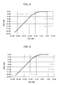
- Figs. 5 and 6 show general Amplitude Modulation (AM)-AM characteristics and AM-Phase Modulation (PM) characteristics of a SSPA(Solid-State Power Amplifier), respectively.
- Input frequency error as TRF data is [-4k, 4kHz].
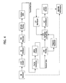
- Fig. 4 illustrates transmission/reception cahin and simulator structure for e-BCH+CPM transmission.
- CPM filtering is performed for reception signal and symbol timing synchronization is performed for reception signal.
- Rife and Boorstyn (R&B) algorithm of data-aieded scheme is applied to Fig. 4 .
- the reception signal is defined by Equation 17 below.
- n refers to an unknown frequency mismatch value
- ⁇ (t) refers to a carrier phase-noise process value.
- the frequency estimator is configured to estimate frequency through the following conventional frequency estimation process.
- the frequency estimator obtains correlation defined by Equation 17 below using known data in the preamble and midamble of a received signal, i.e. signal transmitted from the user terminal.
- Equation 17 parameter D corresponds to a wasted symbol considered by N dist .
- the frequency estimator performs Fast Fourier Transform (FFT), as defined by Equation 18 below.
- FFT Fast Fourier Transform
- Equation 18 ⁇ refers to a pruning factor of Rife and Boorstyn (R&B) algorithm. Zeros are inserted into a signal inputted to the frequency estimator, and the total length of symbols used for frequency estimation is p ( N pre + D + N mid ).
- the frequency estimator combines the two frequency domain-related sequences, which result from Equation 18, as defined by Equation 19 below.
- the frequency estimator obtains k ⁇ , which indicates maximum value
- ⁇ ⁇ k ⁇ ⁇ ⁇ N pre + D + N mid ⁇ T
- the complex envelope of the signal received by the hub station i.e. CPM-modulated signal
- CPM-modulated signal may be expressed, for symbol detection, according to Equation 21 below.
- the pulse p k (t) and symbol ⁇ k , n are major parameters of the CPM function.
- a CPM modulation-based pulse corresponding to '-1' is referred to as a principal component. If L ⁇ 3, it is sufficient to gather energy necessary for transmission. If L ⁇ 3, the value of F and the length of linear filter become larger, making it necessary to increase the length of modulated pulses p k (t) .
- CPM modulation is performed according to a Maximum-Likelihood Sequence Detection (MLSD) based on consideration of the intrinsic memory of CPM signals.
- the demapper in accordance with an embodiment of the present invention applies BCJR algorithm and performs demodulation, assuming coherent demodulation, in order to remove carrier phase error.
- BCJR algorithm a probability value is expressed as data through soft decision during data detection.
- R refers to a value determining the scale of state of a phase value corresponding to 2pi, and has a value of 6p in accordance with an embodiment of the present invention
- p refers to denominator of CPM modulation index h .
- the decoder decodes a signal, which has been channel-encoded by an e-BCH code, using Chase-Pyndiah algorithm.
- a e-BCH code(51, 64) signal channel-encoded is decoded using Chase-Pyndiah algorithm
- the complexity of encoder in terms of logic gate is comparable to or smaller than when 32-states Convolutional Code (CC) is used for encoding.
- CC Convolutional Code
- Fig. 7 shows Packet Error Rate (PER) performance through an AWGN channel when ATM-SAC packet size is 456 bits and spectral efficiency is 0.75 bit/s/Hz.
- PER Packet Error Rate
- Es/N0 Energy per Symbol per Noise Power Spectral Density
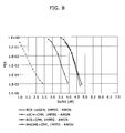
- Fig. 8 shows PER performance through an AWGN channel when 1MPEG packet size is 1504 bits and spectral efficiency is 0.75 bit/s/Hz. The result shown in Fig. 8 is similar to that shown in Fig. 7 .
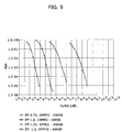
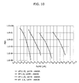
- Figs. 9 and 10 show PER performance and necessary Es/N0 of a satellite communication system 400 based on spectral efficiency described in Table 3.
- Figs. 9 shows PER performance in accordance with spectral efficiency through an AWGN channel when 1MPEG packet size is 1504 bits.
- Figs. 10 shows PER performance in accordance with spectral efficiency through an AWGN channel when ATM-SAC packet size is 456 bits.
- Fig. 11 shows a comparison of PER performance between the present invention and conventional DVB-RCS systemin phase error and phase noise environment. Output Back off power is 0.5dB. The symbol rate and data rate values in terms of spectral efficiency is as below.
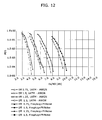
- Figs. 12 shows PER performance of CPM modulation in carrier instability environment and AWGN channel in accordance with spectral efficiency when 1ATM-SAC packet size is 456 bits.
- Figs. 13 shows PER performance of CPM modulation in carrier instability environment and AWGN channel in accordance with spectral efficiency when 1MPEG packet size is 1504 bits.
- Fig. 14 illustrates a SCPC connection scheme for improving data transmission rate in DVB-S2 transmission structure.
- the present invention employs a Multi-Input Multi-Output (MIMO) system and a space-time code to increase the data transmission rate.
- MIMO Multi-Input Multi-Output
- This construction in accordance with the present invention employs a MIMO system and a golden code as a space-time code so that, through polarization reuse, the link throughput doubles.
- the present invention exhibits better performance in a Line-Of-Sight (LOS) environment where transmitting and receiving antennas face each other.
- the golden code can be defined by Equation 22 below.
- Fig. 1 illustrates a transmission structure of digital part of VSAT system terminal.
- Fig. 2 illustrates a burst framing structure
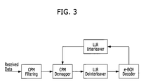
- Fig. 3 illustrates a reception structure of digital part of VSAT system of gateway.
- Fig. 4 illustrates transmission/reception cahin and simulator structure for e-BCH+CPM transmission.
- Figs. 5 shows general. AM(Amplitude Modulation)-AM characteristics of a SSPA.
- Fig. 6 shows general AM-PM (Phase Modulation) characteristics of a SSPA.
- Fig. 7 shows PER performance through an AWGN channel when ATM-SAC packet size is 456 bits and spectral efficiency is 0.75 bit/s/Hz.
- Fig. 8 shows PER performance through an AWGN channel when 1MPEG packet size is 1504 bits and spectral efficiency is 0.75 bit/s/Hz.
- Figs. 9 shows PER performance in accordance with spectral efficiency through an AWGN channel when 1MPEG packet size is 1504 bits.
- Fig. 10 shows PER performance in accordance with spectral efficiency through an AWGN channel when ATM-SAC packet size is 456 bits.
- Fig. 11 shows a comparison of PER performance between the present invention and conventional DVB-RCS system in phase error and phase noise environment.
- Figs. 12 shows PER performance of CPM modulation in carrier instability environment and AWGN channel in accordance with spectral efficiency when 1ATM-SAC packet size is 456 bits.
- Fig. 13 shows PER performance of CPM modulation in carrier instability environment and AWGN channel in accordance with spectral efficiency when 1MPEG packet size is 1504 bits.
- Fig. 14 illustrates a transmission structure in accordance with Polarization Reuse and Golden Code.
Landscapes
- Engineering & Computer Science (AREA)
- Computer Networks & Wireless Communication (AREA)
- Signal Processing (AREA)
- Physics & Mathematics (AREA)
- Astronomy & Astrophysics (AREA)
- Aviation & Aerospace Engineering (AREA)
- General Physics & Mathematics (AREA)
- Radio Relay Systems (AREA)
- Digital Transmission Methods That Use Modulated Carrier Waves (AREA)
Abstract
Description
- Exemplary embodiments of the present invention relate to satellite VSAT(Very Small Aperture Terminal) transmission system.
- A satellite communication system basically includes a hub (or gateway) configured to operate a communication service, a user terminal used by a service subscriber, and a satellite transponder. However, the conventional satellite communication system has a problem in that the distance between the earth station (e.g. hub station, user terminal, etc.) and the satellite transponder may cause transmission delay and signal power attenuation, besides the cost for launching the satellite transponder in the orbit. The satellite communication system, due to the satellite transponder in the orbit, can provide a large area of service coverage. The satellite communication system also employs a high frequency band, i.e. Ku/Ka band, to provide a broadband communication service, increasing the available bandwidth.
- However, the conventional satellite communication system has a problem in that use of the Ku/Ka band for satellite communication requires additional costs for analog devices for up-conversion from the baseband to the Ku/Ka band. The cost problem may make it difficult for the communication service operator to enroll a large number of service subscribers, and development of devices for solving the problem of transmission delay and signal power attenuation may further increase the price of analog devices. The present invention provide transmission scheme using inexpensive analog devices that the data transmission rate doubles whitout extension of bandwidth.
- A VSAT terminal uses analog part (outdoor unit apparatus). Inferior performance of the analog part is caused by phase noise, nonlinear characteristic of SSPA and inaccuracy characteristic of local oscillator. An embodiment of the present invention is directed to a VSAT terminal using a satellite channel, which shows better data transmitting/receiving performance in an interference communication environment. Another embodiment of the present invention is directed to trnasmission technology, which make it possible to economically manufacture or operate a device used in a satellite communication system. Another embodiment of the present invention is directed to transmission structure, which have an improved data transmission rate without extension of bandwidth.
- In accordance with an embodiment of the present invention, a sattellite vsat transmission system, comprising: interleaver structure and transmitting and receiving frame structure for improving efficiency of signal, wherein the sattellite vsat transmission system transmit and receive the signal regardless of packet length of the signal.
- In accordance with the exemplary embodiments of the present invention, the transmission performance in a carrier instability environment, where frequency error, phase noise, and the like occur, is better than in the case of a conventional DVB-RCS system. That is, the present invention provides better transmission performance in an inferior communication environment so that an inexpensive analog device can be used for the user terminal, for example. This consequently reduces the cost for operation and utilization of the satellite communication system. Furthermore, in accordance with the present invention, frequency is reused using a MIMO system, golden code and a space-time code in a satellite communication system, thereby improving the overall data transmission rate doubles.
- Exemplary embodiments of the present invention will be described below in more detail with reference to the accompanying drawings. The present invention may, however, be embodied in different forms and should not be constructed as limited to the embodiments set forth herein. Rather, these embodiments are provided so that this disclosure will be thorough and complete, and will fully convey the scope of the present invention to those skilled in the art. Throughout the disclosure, like reference numerals refer to like parts throughout the various figures and embodiments of the present invention.
- Conventional VSAT systems, when CPM-type modulation is used, usually employ the Gaussian Minimum Shift Keying (GMSK) modulation scheme. However, the GMSK modulation scheme has low spectral efficiency, and makes it difficult to transmit a large amount of data. And convolutional code and turbo code is usually used as channel coding scheme for CPM modulation. The present invention provides a novel method for transmitting/receiving data, which has better transmission performance in an inferior communication environment, and which is applicable to a VSAT system. The present invention, through a return link of a VSAT system, performs channel-encoding using an extended BCH (e-BCH) code, performs interleaving, and transmits the data using a quaternary Continuous Phase Modulation (CPM) scheme using four symbols. The CPM-modulated data is received, and error correction and restoration are performed. That is, in accordance with the present invention, a user terminal in a VSAT system transmits data through e-BCH encoding, interleaving, and CPM modulation, and a hub station in accordance with the present invention receives the data from the user terminal and restores data. In accordance with the present invention, the transmission performance is better in an inferior environment for an analog device compared with conventional DVB-RCS standards. The present invention also transmits data through predetermined interleaving, so that data can be transmitted with no limitation on packet length.
- And the present invention, through a return link of a DVB-S2 satellite broadcasting system of DVB-RCS +M standard, comprises technology in relation to transmission structure that the data transmission efficiency is improved twice.
-
Fig. 1 illustrates a transmission structure of digital part of VSAT system terminal. - Referring to
Fig. 1 , the user terminal in accordance with the present invention includes an e-BCH encoder, a Bit interleaver, a CPM modulator, and a Burst Framing unit(transmitter). an e-BCH encoder is configured to perform channel encoding by means of an e-BCH block code. The embodiment illustrated inFig. 1 is described in connection with channel encoding based on a linear systematic code having k=51, n=64, and dmin =6, wherein k refers to the length (bit unit) of information data among input bit data, n refers to the length (bit unit) of a codeword, and dmin refers to the minimum distance, specifically Hamming distance. In this case, the code rate in the encoder is 51/64.The encoder is configured to generate a matrix G defined byEquation 1 below, wherein I refers to an identify matrix, and P refers to a parity check matrix. The matrix G generated by I and P is a k by n matrix. The parity check matrix is given in Table 1 below. The matrix G generated by the encoder (Generating Matrix) is used to generate a codeword.
- The encoder is configured to divide the input data length K bits by Nb of kshortened bits in order to have the target code rate Rtarget and the same error correction ability for each block, as defined by Equation 2 below. That is, the encoder splits the input data to encode it into a code having k=51 and n=64. Therefore, the target code rate Rtarget becomes smaller than the code rate (k/n) of e-BCH. The target code rate Rtarget may be set by the operator of the satellite communication system.
Table 1 1 0 0 1 1 1 0 0 1 0 1 0 1 0 1 0 0 1 1 1 0 0 1 0 1 1 1 0 1 1 1 0 1 1 1 0 0 0 0 0 1 0 1 1 1 0 1 1 1 0 0 0 0 0 1 0 1 1 1 0 1 1 1 0 0 0 0 0 1 0 1 1 1 0 1 1 1 0 1 0 0 1 0 1 1 1 0 0 0 1 1 1 1 0 1 0 1 1 1 0 0 1 0 0 0 1 1 0 1 0 1 1 1 0 0 1 0 1 0 1 0 1 0 0 1 0 1 1 0 1 0 1 0 1 0 1 0 0 1 0 1 1 1 1 0 1 1 0 1 1 0 1 1 1 1 0 1 1 0 0 0 1 1 1 1 1 0 1 1 1 1 1 1 1 1 1 1 0 1 0 0 0 0 1 1 1 1 1 1 1 1 0 1 0 0 0 0 1 1 1 1 1 1 1 1 0 1 0 1 0 0 0 0 0 1 1 0 1 0 0 1 0 1 0 0 0 0 0 1 1 0 1 0 1 0 0 1 0 0 0 0 0 1 1 0 1 1 1 0 0 0 1 1 0 0 1 1 0 0 0 0 1 0 0 0 1 1 0 0 1 1 0 0 0 0 1 0 0 0 1 1 0 0 1 1 0 1 0 0 0 1 1 0 1 0 0 1 1 1 1 1 0 1 1 0 1 0 0 0 1 1 0 1 1 1 1 0 0 0 1 1 0 1 1 1 1 1 1 0 0 1 0 0 0 1 1 1 0 1 1 1 0 1 1 1 0 1 0 0 1 1 1 1 1 0 1 0 1 1 1 1 1 0 0 0 1 1 1 0 1 0 1 1 1 1 1 0 1 0 1 0 0 1 1 0 0 1 0 1 1 1 1 0 0 1 1 1 1 1 0 0 0 0 0 1 1 0 0 1 1 1 1 1 0 0 0 0 0 1 1 0 0 1 1 1 1 1 0 0 0 0 0 1 1 0 0 1 1 1 1 1 0 1 0 0 1 0 0 0 0 0 1 0 1 1 1 1 0 1 0 1 0 0 1 0 0 0 0 0 1 1 0 1 0 1 0 0 1 0 0 0 0 0 1 1 0 1 0 1 0 0 1 0 0 0 0 0 1 1 0 1 0 1 0 0 1 0 1 0 0 1 0 0 0 1 1 1 1 0 1 0 1 0 0 1 0 0 0 1 1 1 1 1 1 0 1 1 1 0 0 0 1 1 0 1 0 1 1 0 0 0 0 0 0 1 1 0 0 1 0 1 1 0 0 0 0 0 0 1 1 0 1 0 0 1 1 0 0 0 0 0 0 1 1 1 1 0 0 0 0 1 0 0 1 0 1 1 0 1 1 0 1 1 1 1 0 1 1 1 1 1 1 1 1 1 0 0 1 1 1 1 0 1 0 1 1 1 0 0 1 0 1 0 1 0 0 1 0 1 1 1 0 0 1 0 1 0 1 0 1 0 0 1 1 1 0 0 1 0 1 0 1 1 
- In Equation 2, └ ┘ indicates a floor operator, which discards the remainder. The input data length K bit is divided by Nb block. The length of q1 is kshortened + 1, and the length of q2 is kshortened. The Reffective code rate according to Equation 2 may be slightly different from the target code rate Rtarget . In each block divided by Nb, zeros are inserted in front of the packet by the encoder having k bits (u = └0...0, b1b2 ...bk
shortened ┘). The encoder is configured to generate the final codeword c defined by Equation 3 below using the generating matrix G according toEquation 1 and the block divided by Nb , into which zeros have been inserted.
- The bit interleaver is configured to interleave data encoded by the encoder. The interleaver may perform interleaving according to a S-random interleaving (or spread interleaving) scheme defined by Equation 4 below, in order to change burst error, which exists in encoded data, into random error.

- In Equation 4, N refers to the block length divided by Nb, and P1 and P2 are 1103 and 251, respectively.
- The CPM modulator is configured to modulate data, which has been interleaved by the interleaver, through a CPM scheme exhibiting phase continuity characteristics. A method of modulation according to the CMP scheme is defined by
Equation 5 below.
- In
Equation 5, E refers to symbol energy, T refers to symbol time, f0 refers to carrier frequency, and ϕ0 refers to arbitrary fixed phase shift. The ϕ0 may be set to zero for synchronous demodulation. In general, data information is loaded onto the phase value of ϕ(t,α), which is defined by Equation 6 below.
- In Equation 6, α k refers to an uncorrelated information data symbol sequence having similar probability of occurrence, the value of which is one of {±1, ±3, ± (M-1)}, and M refers to constellation cardinality. In accordance with an embodiment of the present invention, M=4, and as described above, the modulator 105 performs modulation in a CPM scheme using four symbols. The CPM scheme having M=4 will hereinafter be referred to as a quaternary CPM scheme. When M=4, αk can be gray-mapped onto four symbols as shown in Table 2 below.
Table 2 Bits Symbol 00 -3 01 -1 11 1 10 3 - In Equation 6 below, h refers to modulation index. A general CPM scheme will now be described. Modulation according to a CPM scheme requires that the frequency pulse g(t) in Equation 6 satisfy the condition defined by Equation 7 below.

- In Equation 7, L refers to the CPM memory length, and T refers to symbol interval.
- A phase response to a baseband is defined by Equation 8 below.

- And function q(t) in Equation 8 must satisfy the condition defined by Equation 9 below.

- Using Equations 7 to 9, Equation 6 can be expressed without integration operation, as defined by Equation 10 below.

- phase impulse shape g(t) according to the quaternary CPM scheme can be expressed in terms of a Raised-Cosine (RC) function as defined by Equation 11.

- Using Equation 12, Equation 10 can be rewritten into Equation 13.


- In Equation 13, θ n refers to a phase state at time n-L, θ(t,α n) refers to a partial response from time n-L to time n, and L>1 in this case. In other words, a partial response signal ϕ(t,α n) in an arbitrary symbol interval n is defined by the current data symbol α n , and, at symbol n-L, defined as a correlative state vector (α n-1, α n-2..., α n-L+1 ) and phase state θ n . When L=1, the correlative state vector becomes an empty vector. Assuming that h refers to a ratio between prime numbers, i.e. the modulation index is expressed as a ratio to a prime number, h=m/p, and every possible phase state value, θn, can be expressed by Equation 14 below.

- CPM modulation can be expressed as a time-variant trellis having a modulation state defined by vector δ n = (θ n, α n-1, α n-2 ,..., α n-L+ 1). The correlative state is influenced by the last n-
L+ 1 data symbol, and the phase state transition is calculated by Equation 15 below.
- Due to memory limitation, detection of a CPM signal requires a decoder-based trellis. The CPM state number, Ns , is calculated by Equation 16 below.

- A burst frame transmitted through a return link in a conventional DVB-RCS system has a structure including a preamble Npre (0<Npre <256) and information data, but a burst frame in accordance with the present invention includes, as illustrated in
Fig. 2 , a preamble Npre, information data Ndist, wasted symbols, a midamble Nmia, and remaining data. The information data and remaining data may vary depending on the size of input data. The wasted symbols are inserted between the preamble and the midamble so that the receiving side can change the modulation state into a predetermined known state. More specifically, when a CPM signal is transmitted, the receiving side, even when knowing the ith transmitted symbol, needs to know the CPM signal in time interval [iT; kT+T]. Considering this, the user terminal transmits wasted symbols to the receiving side (hub station) so that the receiving side can change the modulation state into a predetermined known state. The amount of wasted symbols, also referred to as a state-forcing sequence, depends on the CPM format regardless of whether useful information is transmitted or symbols for channel estimation are transmitted. The length of wasted symbols is determined by L-1+┌p/M┐, wherein ┌x┐ refers to an integer smaller than x. - Meanwhile, since the band of CPM has an infinite value, an effective frequency band capable of isolating an adjacent channel user is important. In addition, selection of a power ratio for defining the effective frequency band is also important. In accordance with an embodiment of the present invention, the power ratio for defining the effective frequency band is 99%, and the relationship between spectral efficiency, target code rate Rtarget , CPM scheme, and effective frequency band (BW99%) is given in Table 3 below.
Table 3 Spectral Efficiency e-BCH Rtarget CPM Scheme BW99% [normalized to T] 0.75 bit/s/Hz 0.7053 Q2RC, h=3/7 1.8773 1.00 bit/s/Hz 0.7162 Q2RC, h=2/7 1.3772 1.25 bit/s/Hz 0.7048 Q3RC, h=2/7 1.1193 1.50 bit/s/Hz 0.7689 Q3RC, h=1/4 1.0151 -
Figs. 5 and 6 show general Amplitude Modulation (AM)-AM characteristics and AM-Phase Modulation (PM) characteristics of a SSPA(Solid-State Power Amplifier), respectively. Input frequency error as TRF data is [-4k, 4kHz].Fig. 4 illustrates transmission/reception cahin and simulator structure for e-BCH+CPM transmission. InFig. 4 , CPM filtering is performed for reception signal and symbol timing synchronization is performed for reception signal. Rife and Boorstyn (R&B) algorithm of data-aieded scheme is applied toFig. 4 . And the reception signal is defined by Equation 17 below. In Equation 17, n refers to an unknown frequency mismatch value, θ(t) refers to a carrier phase-noise process value. The frequency estimator is configured to estimate frequency through the following conventional frequency estimation process. - The frequency estimator obtains correlation defined by Equation 17 below using known data in the preamble and midamble of a received signal, i.e. signal transmitted from the user terminal.

- In Equation 17, parameter D corresponds to a wasted symbol considered by Ndist.
- The frequency estimator performs Fast Fourier Transform (FFT), as defined by Equation 18 below.
- In Equation 18, ρ refers to a pruning factor of Rife and Boorstyn (R&B) algorithm. Zeros are inserted into a signal inputted to the frequency estimator, and the total length of symbols used for frequency estimation is p(Npre +D+Nmid ).

- The frequency estimator combines the two frequency domain-related sequences, which result from Equation 18, as defined by Equation 19 below.

- The frequency estimator obtains k̂, which indicates maximum value |Zk |2, using the result of Equation 19, and obtains a frequency mismatch value using Equation 20 below.

- Meanwhile, the complex envelope of the signal received by the hub station, i.e. CPM-modulated signal, may be expressed, for symbol detection, according to Equation 21 below.

- In Equation 21, F=(M-1)*2(L-1)logM, which indicates the number of modulated pulses pk(t), and β k,n refers to a pseudo-symbol. The pulse pk(t) and symbol β k,n are major parameters of the CPM function. In order to reduce the complexity of the demodulator, the condition of S<F may be used for linear filtering by the filter, wherein S=(M-1)ML-1, F=(M-1)*2(L-1)logM. Among the first four symbols (M=4), a CPM modulation-based pulse corresponding to '-1' is referred to as a principal component. If L<3, it is sufficient to gather energy necessary for transmission. If L≥3, the value of F and the length of linear filter become larger, making it necessary to increase the length of modulated pulses p k (t).
- In general, CPM modulation is performed according to a Maximum-Likelihood Sequence Detection (MLSD) based on consideration of the intrinsic memory of CPM signals. However, the demapper in accordance with an embodiment of the present invention applies BCJR algorithm and performs demodulation, assuming coherent demodulation, in order to remove carrier phase error. According to the BCJR algorithm, a probability value is expressed as data through soft decision during data detection. When phase noise is considered, phase synchronization technology by the demapper may be combined with the BCJR algorithm through Bayesian technique. In this case, actually implementable

- The decoder decodes a signal, which has been channel-encoded by an e-BCH code, using Chase-Pyndiah algorithm. when a e-BCH code(51, 64) signal channel-encoded is decoded using Chase-Pyndiah algorithm, the complexity of encoder in terms of logic gate is comparable to or smaller than when 32-states Convolutional Code (CC) is used for encoding. The number of times is set to a maximum of 30 times between CPM modulation and e-BCH decoder.
-
Fig. 7 shows Packet Error Rate (PER) performance through an AWGN channel when ATM-SAC packet size is 456 bits and spectral efficiency is 0.75 bit/s/Hz. InFig. 7 , the lower the PER and Energy per Symbol per Noise Power Spectral Density (Es/N0) are, the better the performance is. It is clear fromFig. 7 that, when the satellite communication system 400 includes no analog device (SSPA) and is in no carrier instability environment, the conventional DVB-RCS-based scheme, i.e. RCS 1st GEN exhibits the best PER performance. Furthermore, combined use of a conventional turbo code with a CPM scheme deteriorates performance, and the result in accordance with the present invention has inferior performance than the conventional DVB-RCS-based scheme.Fig. 8 shows PER performance through an AWGN channel when 1MPEG packet size is 1504 bits and spectral efficiency is 0.75 bit/s/Hz. The result shown inFig. 8 is similar to that shown inFig. 7 . -
Figs. 9 and10 show PER performance and necessary Es/N0 of a satellite communication system 400 based on spectral efficiency described in Table 3. - Specifically,
Figs. 9 shows PER performance in accordance with spectral efficiency through an AWGN channel when 1MPEG packet size is 1504 bits.Figs. 10 shows PER performance in accordance with spectral efficiency through an AWGN channel when ATM-SAC packet size is 456 bits. -
Fig. 11 shows a comparison of PER performance between the present invention and conventional DVB-RCS systemin phase error and phase noise environment. Output Back off power is 0.5dB. The symbol rate and data rate values in terms of spectral efficiency is as below. - RCS 1st generation: 380 kBaud and equivalently 380 kbit/s (1/2-QPSK);
- e-BCH+CPM, Eff. 0.75: 273 kBaud and equivalently 380 kbit/s;
- e-BCH+CPM, Eff. 1.0: 372 kBaud and equivalently 520 kbit/s;
- e-BCH+CPM, Eff. 1.25: 458 kBaud and equivalently 640 kbit/s;
- e-BCH+CPM, Eff. 1.5: 506 kBaud and equivalently 768 kbit/s;
- In
Fig. 11 , the preamble length of a conventional DVB-RCS burst frame is 48, and a burst frame in accordance with the present invention has a structure of: Npre=Nmid=32, Ndist=30. It is clear fromFig. 11 that, in a carrier instability environment, the method for transmitting/receiving data in accordance with the present invention exhibits better PER performance than the conventional DVB-RCS scheme. In accordance with the present invention, degradation caused by frequency and phase noise is 0.2-0.4 dB, which means better performance than conventional DVB-RCS. -
Figs. 12 shows PER performance of CPM modulation in carrier instability environment and AWGN channel in accordance with spectral efficiency when 1ATM-SAC packet size is 456 bits.Figs. 13 shows PER performance of CPM modulation in carrier instability environment and AWGN channel in accordance with spectral efficiency when 1MPEG packet size is 1504 bits. -
Fig. 14 illustrates a SCPC connection scheme for improving data transmission rate in DVB-S2 transmission structure. The present invention employs a Multi-Input Multi-Output (MIMO) system and a space-time code to increase the data transmission rate. This construction in accordance with the present invention employs a MIMO system and a golden code as a space-time code so that, through polarization reuse, the link throughput doubles. The present invention exhibits better performance in a Line-Of-Sight (LOS) environment where transmitting and receiving antennas face each other. The golden code can be defined by Equation 22 below.
- In Equation 22, S1, S2, S3, and S4 refer to complex-valued information symbols, θ refers to a golden number

wherein,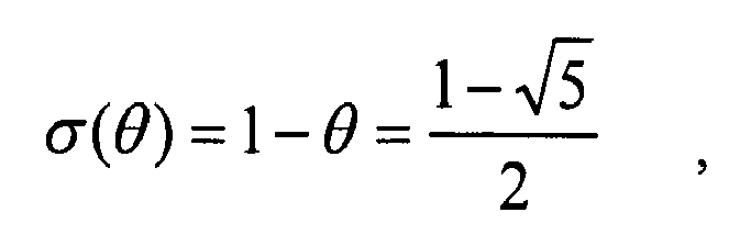

-
Fig. 1 illustrates a transmission structure of digital part of VSAT system terminal. -
Fig. 2 illustrates a burst framing structure. -
Fig. 3 illustrates a reception structure of digital part of VSAT system of gateway. -
Fig. 4 illustrates transmission/reception cahin and simulator structure for e-BCH+CPM transmission. -
Figs. 5 shows general. AM(Amplitude Modulation)-AM characteristics of a SSPA. -
Fig. 6 shows general AM-PM (Phase Modulation) characteristics of a SSPA. -
Fig. 7 shows PER performance through an AWGN channel when ATM-SAC packet size is 456 bits and spectral efficiency is 0.75 bit/s/Hz. -
Fig. 8 shows PER performance through an AWGN channel when 1MPEG packet size is 1504 bits and spectral efficiency is 0.75 bit/s/Hz. -
Figs. 9 shows PER performance in accordance with spectral efficiency through an AWGN channel when 1MPEG packet size is 1504 bits. -
Fig. 10 shows PER performance in accordance with spectral efficiency through an AWGN channel when ATM-SAC packet size is 456 bits. -
Fig. 11 shows a comparison of PER performance between the present invention and conventional DVB-RCS system in phase error and phase noise environment. -
Figs. 12 shows PER performance of CPM modulation in carrier instability environment and AWGN channel in accordance with spectral efficiency when 1ATM-SAC packet size is 456 bits. -
Fig. 13 shows PER performance of CPM modulation in carrier instability environment and AWGN channel in accordance with spectral efficiency when 1MPEG packet size is 1504 bits. -
Fig. 14 illustrates a transmission structure in accordance with Polarization Reuse and Golden Code.
Claims (1)
- A sattellite vsat transmission system, comprising:interleaver structure and transmitting and receiving frame structure for improving efficiency of signal,wherein the sattellite vsat transmission system transmit and receive the signal regardless of packet length of the signal.
Priority Applications (1)
| Application Number | Priority Date | Filing Date | Title |
|---|---|---|---|
| EP13162680.6A EP2615759A3 (en) | 2009-05-04 | 2010-05-04 | Method and apparatus for transmitting/receiving data using satellite channel |
Applications Claiming Priority (1)
| Application Number | Priority Date | Filing Date | Title |
|---|---|---|---|
| KR20090039030 | 2009-05-04 |
Related Parent Applications (1)
| Application Number | Title | Priority Date | Filing Date |
|---|---|---|---|
| KR20090039030 Previously-Filed-Application | 2009-05-04 |
Related Child Applications (2)
| Application Number | Title | Priority Date | Filing Date |
|---|---|---|---|
| EP13162680.6A Division-Into EP2615759A3 (en) | 2009-05-04 | 2010-05-04 | Method and apparatus for transmitting/receiving data using satellite channel |
| EP13162680.6A Division EP2615759A3 (en) | 2009-05-04 | 2010-05-04 | Method and apparatus for transmitting/receiving data using satellite channel |
Publications (2)
| Publication Number | Publication Date |
|---|---|
| EP2249501A2 true EP2249501A2 (en) | 2010-11-10 |
| EP2249501A3 EP2249501A3 (en) | 2014-02-19 |
Family
ID=42562956
Family Applications (2)
| Application Number | Title | Priority Date | Filing Date |
|---|---|---|---|
| EP13162680.6A Withdrawn EP2615759A3 (en) | 2009-05-04 | 2010-05-04 | Method and apparatus for transmitting/receiving data using satellite channel |
| EP10161901.3A Withdrawn EP2249501A3 (en) | 2009-05-04 | 2010-05-04 | Method and apparatus for transmitting/receiving data using satellite channel |
Family Applications Before (1)
| Application Number | Title | Priority Date | Filing Date |
|---|---|---|---|
| EP13162680.6A Withdrawn EP2615759A3 (en) | 2009-05-04 | 2010-05-04 | Method and apparatus for transmitting/receiving data using satellite channel |
Country Status (3)
| Country | Link |
|---|---|
| US (1) | US20100316161A1 (en) |
| EP (2) | EP2615759A3 (en) |
| KR (1) | KR20100120094A (en) |
Cited By (3)
| Publication number | Priority date | Publication date | Assignee | Title |
|---|---|---|---|---|
| CN107979448A (en) * | 2015-03-13 | 2018-05-01 | 清华大学 | Interweaved the error control method mapped based on perforation |
| CN112350767A (en) * | 2020-10-30 | 2021-02-09 | 西南电子技术研究所(中国电子科技集团公司第十研究所) | TDRSS ground station information frame equalization modulation method |
| CN114710192A (en) * | 2022-03-11 | 2022-07-05 | 中国科学院国家空间科学中心 | Satellite-borne heaven-sea relay communication system and method applied to low-earth satellite |
Families Citing this family (6)
| Publication number | Priority date | Publication date | Assignee | Title |
|---|---|---|---|---|
| KR101490252B1 (en) * | 2008-01-28 | 2015-02-05 | 엘지전자 주식회사 | Signal transmission and decoding method considering repeatedly transmitted information |
| US8259863B2 (en) * | 2008-01-28 | 2012-09-04 | Lg Electronics Inc. | Method for transmitting and decoding signals considering repeatedly transmitted information |
| US9276704B1 (en) * | 2014-12-15 | 2016-03-01 | Intel Corporation | Maximum likelihood sequence detection in the phase domain |
| KR102234495B1 (en) * | 2015-01-26 | 2021-03-31 | 한국전자통신연구원 | Method for cancellating interference in satellite communications system and satellite communications system |
| EP3427427B1 (en) * | 2016-04-12 | 2025-07-02 | Huawei Technologies Co., Ltd. | Methods and apparatus for signal spreading and multiplexing |
| CN113783642B (en) * | 2021-08-25 | 2023-06-30 | 中国电子科技集团公司第三十八研究所 | Multi-beam high-flux link modeling simulation system |
Family Cites Families (12)
| Publication number | Priority date | Publication date | Assignee | Title |
|---|---|---|---|---|
| US3818442A (en) * | 1972-11-08 | 1974-06-18 | Trw Inc | Error-correcting decoder for group codes |
| US5103459B1 (en) * | 1990-06-25 | 1999-07-06 | Qualcomm Inc | System and method for generating signal waveforms in a cdma cellular telephone system |
| US5712877A (en) * | 1995-05-26 | 1998-01-27 | Simon Fraser University | Pilot-symbol aided continuous phase modulation system |
| US5721877A (en) * | 1995-05-31 | 1998-02-24 | Ast Research, Inc. | Method and apparatus for limiting access to nonvolatile memory device |
| US6240073B1 (en) * | 1997-11-14 | 2001-05-29 | Shiron Satellite Communications (1996) Ltd. | Reverse link for a satellite communication network |
| EP1404034B1 (en) * | 2000-04-04 | 2008-11-26 | Mitsubishi Electric Information Technology Centre Europe B.V. | Base station for transmitting a word representative of the number of spreading codes allocated to the mobile stations in communication with the base station |
| US7054286B2 (en) * | 2000-10-27 | 2006-05-30 | L-3 Communications Corporation | Bandwidth allocation and data multiplexing scheme for direct sequence CDMA systems |
| US6968021B1 (en) * | 2001-09-24 | 2005-11-22 | Rockwell Collins | Synchronization method and apparatus for modems based on jointly iterative turbo demodulation and decoding |
| CN1663144B (en) * | 2002-06-26 | 2010-04-28 | 美国博通公司 | Apparatus and method for space-time turbo coded modulation |
| US7281174B1 (en) * | 2004-10-01 | 2007-10-09 | Rockwell Collins, Inc. | Diversity code combining scheme for turbo coded systems |
| EP1863191B1 (en) * | 2006-06-02 | 2012-03-14 | STMicroelectronics N.V. | Method for managing eventual interferences with antenna switching and corresponding device |
| US8352840B2 (en) * | 2008-03-25 | 2013-01-08 | Her Majesty The Queen in Right of Canada, As Represented by The Minister of Industry, Through The Commincations Research Centre Canada | Event cleanup processing for improving the performance of sequence-based decoders |
-
2010
- 2010-05-04 EP EP13162680.6A patent/EP2615759A3/en not_active Withdrawn
- 2010-05-04 US US12/773,568 patent/US20100316161A1/en not_active Abandoned
- 2010-05-04 EP EP10161901.3A patent/EP2249501A3/en not_active Withdrawn
- 2010-05-04 KR KR1020100042010A patent/KR20100120094A/en not_active Ceased
Non-Patent Citations (1)
| Title |
|---|
| None |
Cited By (9)
| Publication number | Priority date | Publication date | Assignee | Title |
|---|---|---|---|---|
| CN107979448A (en) * | 2015-03-13 | 2018-05-01 | 清华大学 | Interweaved the error control method mapped based on perforation |
| CN108023681A (en) * | 2015-03-13 | 2018-05-11 | 清华大学 | Interweaved the error control method mapped based on perforation |
| CN108282267A (en) * | 2015-03-13 | 2018-07-13 | 清华大学 | Error control method based on perforation intertexture mapping |
| CN107979448B (en) * | 2015-03-13 | 2020-06-05 | 清华大学 | Error Control Method Based on Punctured Interleaving Mapping |
| CN108023681B (en) * | 2015-03-13 | 2020-06-05 | 清华大学 | Error Control Method Based on Punctured Interleaving Mapping |
| CN108282267B (en) * | 2015-03-13 | 2020-06-05 | 清华大学 | Error Control Method Based on Punctured Interleaving Mapping |
| CN112350767A (en) * | 2020-10-30 | 2021-02-09 | 西南电子技术研究所(中国电子科技集团公司第十研究所) | TDRSS ground station information frame equalization modulation method |
| CN114710192A (en) * | 2022-03-11 | 2022-07-05 | 中国科学院国家空间科学中心 | Satellite-borne heaven-sea relay communication system and method applied to low-earth satellite |
| CN114710192B (en) * | 2022-03-11 | 2023-11-17 | 中国科学院国家空间科学中心 | A spaceborne Tianhai relay communication system and method applied to low-orbit satellites |
Also Published As
| Publication number | Publication date |
|---|---|
| US20100316161A1 (en) | 2010-12-16 |
| KR20100120094A (en) | 2010-11-12 |
| EP2249501A3 (en) | 2014-02-19 |
| EP2615759A2 (en) | 2013-07-17 |
| EP2615759A3 (en) | 2014-02-19 |
Similar Documents
| Publication | Publication Date | Title |
|---|---|---|
| EP2615759A2 (en) | Method and apparatus for transmitting/receiving data using satellite channel | |
| EP2223483B1 (en) | Blind turbo channel estimation | |
| EP2421213B1 (en) | Phase pulse system and method for bandwidth and energy efficient continuous phase modulation | |
| US6678263B1 (en) | Method and constructions for space-time codes for PSK constellations for spatial diversity in multiple-element antenna systems | |
| US9634797B2 (en) | Method of transmitting a digital signal for a semi-orthogonal MS-marc system, and a corresponding program product and relay device | |
| CN102075487B (en) | Multidimensional constellation mapping based coding and modulating method, demodulating and decoding method and system | |
| US8301967B2 (en) | Turbo coding for upstream and downstream transmission in cable systems | |
| EP2031785A1 (en) | System for transmitting information data from a transmitter to a receiver over a nested block channel | |
| US20030012372A1 (en) | System and method for joint encryption and error-correcting coding | |
| US6581179B1 (en) | Methods for generating side information in the presence of time-selective fading | |
| KR980013022A (en) | Satellite Communication System Using Parallel Dependent Coding | |
| EP3998709A1 (en) | Modulation mapping method and device for coded symbol based on larger-than-binary field and computer storage medium | |
| CN102742201A (en) | Method for transmitting a digital signal for a semi-orthogonal frame system having half-duplex relay, and corresponding program product and relay device | |
| Sklar | A structured overview of digital communications--A tutorial review--Part II | |
| EP2385662B1 (en) | Improved continuous phase modulation for satellite communications | |
| Vinck | Coding concepts and reed-solomon codes | |
| EP2706667A1 (en) | Method and apparatus for a parameterized interleaver design process | |
| CN102612822A (en) | Method for transmitting digital signals for multi-access relay channel system with half-duplex relay, and corresponding program product and relay device | |
| US7684510B2 (en) | Apparatus and method for transmission which encoding a message with space-time tubo code using feedback bit in mobile communication system | |
| US20030128777A1 (en) | Decision directed phase locked loops (DD-PLL) with multiple initial phase and/or frequency estimates in digital communication systems | |
| US20060045213A1 (en) | Decoding error correcting codes transmitted through multiple wire twisted pair cables with uneven noise on the wires | |
| US20030112899A1 (en) | Decision directed phase locked loops (DD-PLL) with excess processing power in digital communication systems | |
| Ogundile et al. | A low complexity iterative channel estimation and decoding receiver based on reed-solomon PTA | |
| Qazi et al. | Performance Evaluation of Error Correcting Techniques for OFDM Systems | |
| Dey | Simulation based bit error rate measurement of uncoded, coded and encrypted wireless communication channel |
Legal Events
| Date | Code | Title | Description |
|---|---|---|---|
| PUAI | Public reference made under article 153(3) epc to a published international application that has entered the european phase |
Free format text: ORIGINAL CODE: 0009012 |
|
| AK | Designated contracting states |
Kind code of ref document: A2 Designated state(s): AL AT BE BG CH CY CZ DE DK EE ES FI FR GB GR HR HU IE IS IT LI LT LU LV MC MK MT NL NO PL PT RO SE SI SK SM TR |
|
| AX | Request for extension of the european patent |
Extension state: BA ME RS |
|
| PUAL | Search report despatched |
Free format text: ORIGINAL CODE: 0009013 |
|
| AK | Designated contracting states |
Kind code of ref document: A3 Designated state(s): AL AT BE BG CH CY CZ DE DK EE ES FI FR GB GR HR HU IE IS IT LI LT LU LV MC MK MT NL NO PL PT RO SE SI SK SM TR |
|
| AX | Request for extension of the european patent |
Extension state: BA ME RS |
|
| RIC1 | Information provided on ipc code assigned before grant |
Ipc: H04B 7/185 20060101ALI20140110BHEP Ipc: H04L 1/00 20060101AFI20140110BHEP Ipc: H04L 27/20 20060101ALI20140110BHEP |
|
| STAA | Information on the status of an ep patent application or granted ep patent |
Free format text: STATUS: THE APPLICATION IS DEEMED TO BE WITHDRAWN |
|
| 18D | Application deemed to be withdrawn |
Effective date: 20140820 |