EP2249416A1 - Lithium-ion secondary battery and manufacturing method thereof - Google Patents
Lithium-ion secondary battery and manufacturing method thereof Download PDFInfo
- Publication number
- EP2249416A1 EP2249416A1 EP09716454A EP09716454A EP2249416A1 EP 2249416 A1 EP2249416 A1 EP 2249416A1 EP 09716454 A EP09716454 A EP 09716454A EP 09716454 A EP09716454 A EP 09716454A EP 2249416 A1 EP2249416 A1 EP 2249416A1
- Authority
- EP
- European Patent Office
- Prior art keywords
- current collector
- positive electrode
- electrode current
- negative electrode
- exposed portion
- Prior art date
- Legal status (The legal status is an assumption and is not a legal conclusion. Google has not performed a legal analysis and makes no representation as to the accuracy of the status listed.)
- Withdrawn
Links
- HBBGRARXTFLTSG-UHFFFAOYSA-N Lithium ion Chemical compound [Li+] HBBGRARXTFLTSG-UHFFFAOYSA-N 0.000 title claims abstract description 29
- 229910001416 lithium ion Inorganic materials 0.000 title claims abstract description 29
- 238000004519 manufacturing process Methods 0.000 title claims description 14
- 230000004907 flux Effects 0.000 claims abstract description 41
- 229910052782 aluminium Inorganic materials 0.000 claims abstract description 33
- XAGFODPZIPBFFR-UHFFFAOYSA-N aluminium Chemical compound [Al] XAGFODPZIPBFFR-UHFFFAOYSA-N 0.000 claims abstract description 33
- 238000003466 welding Methods 0.000 claims abstract description 31
- 238000004804 winding Methods 0.000 claims abstract description 20
- KRHYYFGTRYWZRS-UHFFFAOYSA-M Fluoride anion Chemical compound [F-] KRHYYFGTRYWZRS-UHFFFAOYSA-M 0.000 claims abstract description 15
- 239000011888 foil Substances 0.000 claims abstract description 15
- 230000009972 noncorrosive effect Effects 0.000 claims abstract description 15
- 239000007774 positive electrode material Substances 0.000 claims abstract description 15
- 239000007773 negative electrode material Substances 0.000 claims description 14
- 239000011810 insulating material Substances 0.000 claims description 13
- KLZUFWVZNOTSEM-UHFFFAOYSA-K Aluminium flouride Chemical compound F[Al](F)F KLZUFWVZNOTSEM-UHFFFAOYSA-K 0.000 claims description 8
- 238000000034 method Methods 0.000 claims description 7
- ZLMJMSJWJFRBEC-UHFFFAOYSA-N Potassium Chemical compound [K] ZLMJMSJWJFRBEC-UHFFFAOYSA-N 0.000 claims description 6
- 230000005496 eutectics Effects 0.000 claims description 6
- 229910052700 potassium Inorganic materials 0.000 claims description 6
- 239000011591 potassium Substances 0.000 claims description 6
- 238000010030 laminating Methods 0.000 claims description 3
- SGPGESCZOCHFCL-UHFFFAOYSA-N Tilisolol hydrochloride Chemical compound [Cl-].C1=CC=C2C(=O)N(C)C=C(OCC(O)C[NH2+]C(C)(C)C)C2=C1 SGPGESCZOCHFCL-UHFFFAOYSA-N 0.000 claims 4
- 239000000203 mixture Substances 0.000 description 17
- 230000000052 comparative effect Effects 0.000 description 10
- 239000011230 binding agent Substances 0.000 description 8
- -1 polyethylene Polymers 0.000 description 7
- 239000002002 slurry Substances 0.000 description 7
- WHXSMMKQMYFTQS-UHFFFAOYSA-N Lithium Chemical compound [Li] WHXSMMKQMYFTQS-UHFFFAOYSA-N 0.000 description 6
- 229910052744 lithium Inorganic materials 0.000 description 6
- 229920005989 resin Polymers 0.000 description 6
- 239000011347 resin Substances 0.000 description 6
- 239000002033 PVDF binder Substances 0.000 description 5
- 238000005219 brazing Methods 0.000 description 5
- 239000004020 conductor Substances 0.000 description 5
- 239000000463 material Substances 0.000 description 5
- 229910052751 metal Inorganic materials 0.000 description 5
- 239000002184 metal Substances 0.000 description 5
- 229920002981 polyvinylidene fluoride Polymers 0.000 description 5
- OKTJSMMVPCPJKN-UHFFFAOYSA-N Carbon Chemical compound [C] OKTJSMMVPCPJKN-UHFFFAOYSA-N 0.000 description 4
- RYGMFSIKBFXOCR-UHFFFAOYSA-N Copper Chemical compound [Cu] RYGMFSIKBFXOCR-UHFFFAOYSA-N 0.000 description 4
- 238000000465 moulding Methods 0.000 description 4
- XLYOFNOQVPJJNP-UHFFFAOYSA-N water Substances O XLYOFNOQVPJJNP-UHFFFAOYSA-N 0.000 description 4
- YXFVVABEGXRONW-UHFFFAOYSA-N Toluene Chemical compound CC1=CC=CC=C1 YXFVVABEGXRONW-UHFFFAOYSA-N 0.000 description 3
- 230000002411 adverse Effects 0.000 description 3
- 239000003125 aqueous solvent Substances 0.000 description 3
- 239000003575 carbonaceous material Substances 0.000 description 3
- 230000007797 corrosion Effects 0.000 description 3
- 238000005260 corrosion Methods 0.000 description 3
- VLKZOEOYAKHREP-UHFFFAOYSA-N n-Hexane Chemical compound CCCCCC VLKZOEOYAKHREP-UHFFFAOYSA-N 0.000 description 3
- 239000011255 nonaqueous electrolyte Substances 0.000 description 3
- 239000002245 particle Substances 0.000 description 3
- KMTRUDSVKNLOMY-UHFFFAOYSA-N Ethylene carbonate Chemical compound O=C1OCCO1 KMTRUDSVKNLOMY-UHFFFAOYSA-N 0.000 description 2
- 239000004743 Polypropylene Substances 0.000 description 2
- 239000006230 acetylene black Substances 0.000 description 2
- 229910021383 artificial graphite Inorganic materials 0.000 description 2
- 229910052802 copper Inorganic materials 0.000 description 2
- 239000010949 copper Substances 0.000 description 2
- 239000011889 copper foil Substances 0.000 description 2
- 239000003792 electrolyte Substances 0.000 description 2
- JBTWLSYIZRCDFO-UHFFFAOYSA-N ethyl methyl carbonate Chemical compound CCOC(=O)OC JBTWLSYIZRCDFO-UHFFFAOYSA-N 0.000 description 2
- 238000010438 heat treatment Methods 0.000 description 2
- 229910003002 lithium salt Inorganic materials 0.000 description 2
- 159000000002 lithium salts Chemical class 0.000 description 2
- 238000005259 measurement Methods 0.000 description 2
- 239000003960 organic solvent Substances 0.000 description 2
- 230000002093 peripheral effect Effects 0.000 description 2
- 229920001155 polypropylene Polymers 0.000 description 2
- 238000003825 pressing Methods 0.000 description 2
- 238000007789 sealing Methods 0.000 description 2
- 229920000049 Carbon (fiber) Polymers 0.000 description 1
- 229920002134 Carboxymethyl cellulose Polymers 0.000 description 1
- VEXZGXHMUGYJMC-UHFFFAOYSA-M Chloride anion Chemical compound [Cl-] VEXZGXHMUGYJMC-UHFFFAOYSA-M 0.000 description 1
- 229910032387 LiCoO2 Inorganic materials 0.000 description 1
- 229910003005 LiNiO2 Inorganic materials 0.000 description 1
- 229910001290 LiPF6 Inorganic materials 0.000 description 1
- 229910002097 Lithium manganese(III,IV) oxide Inorganic materials 0.000 description 1
- 229920003171 Poly (ethylene oxide) Polymers 0.000 description 1
- 239000004698 Polyethylene Substances 0.000 description 1
- 239000004793 Polystyrene Substances 0.000 description 1
- 229920002472 Starch Polymers 0.000 description 1
- 230000005856 abnormality Effects 0.000 description 1
- 150000001338 aliphatic hydrocarbons Chemical class 0.000 description 1
- PNEYBMLMFCGWSK-UHFFFAOYSA-N aluminium oxide Inorganic materials [O-2].[O-2].[O-2].[Al+3].[Al+3] PNEYBMLMFCGWSK-UHFFFAOYSA-N 0.000 description 1
- 150000004945 aromatic hydrocarbons Chemical class 0.000 description 1
- 230000015572 biosynthetic process Effects 0.000 description 1
- 229910052792 caesium Inorganic materials 0.000 description 1
- TVFDJXOCXUVLDH-UHFFFAOYSA-N caesium atom Chemical compound [Cs] TVFDJXOCXUVLDH-UHFFFAOYSA-N 0.000 description 1
- 239000004917 carbon fiber Substances 0.000 description 1
- 239000001768 carboxy methyl cellulose Substances 0.000 description 1
- 235000010948 carboxy methyl cellulose Nutrition 0.000 description 1
- 239000008112 carboxymethyl-cellulose Substances 0.000 description 1
- 239000003795 chemical substances by application Substances 0.000 description 1
- 239000002131 composite material Substances 0.000 description 1
- 229910052593 corundum Inorganic materials 0.000 description 1
- IEJIGPNLZYLLBP-UHFFFAOYSA-N dimethyl carbonate Chemical compound COC(=O)OC IEJIGPNLZYLLBP-UHFFFAOYSA-N 0.000 description 1
- 238000007599 discharging Methods 0.000 description 1
- 238000006073 displacement reaction Methods 0.000 description 1
- 238000001035 drying Methods 0.000 description 1
- 230000000694 effects Effects 0.000 description 1
- 238000010894 electron beam technology Methods 0.000 description 1
- 238000011156 evaluation Methods 0.000 description 1
- 230000002349 favourable effect Effects 0.000 description 1
- 229910002804 graphite Inorganic materials 0.000 description 1
- 239000010439 graphite Substances 0.000 description 1
- 238000007689 inspection Methods 0.000 description 1
- 238000003475 lamination Methods 0.000 description 1
- MHCFAGZWMAWTNR-UHFFFAOYSA-M lithium perchlorate Chemical compound [Li+].[O-]Cl(=O)(=O)=O MHCFAGZWMAWTNR-UHFFFAOYSA-M 0.000 description 1
- 229910001486 lithium perchlorate Inorganic materials 0.000 description 1
- 229910001496 lithium tetrafluoroborate Inorganic materials 0.000 description 1
- VNWKTOKETHGBQD-UHFFFAOYSA-N methane Chemical compound C VNWKTOKETHGBQD-UHFFFAOYSA-N 0.000 description 1
- 239000012046 mixed solvent Substances 0.000 description 1
- 229910052759 nickel Inorganic materials 0.000 description 1
- 239000002006 petroleum coke Substances 0.000 description 1
- 229920002037 poly(vinyl butyral) polymer Polymers 0.000 description 1
- 229920000573 polyethylene Polymers 0.000 description 1
- 229920002223 polystyrene Polymers 0.000 description 1
- 229920000036 polyvinylpyrrolidone Polymers 0.000 description 1
- 239000001267 polyvinylpyrrolidone Substances 0.000 description 1
- 235000013855 polyvinylpyrrolidone Nutrition 0.000 description 1
- 239000000843 powder Substances 0.000 description 1
- RUOJZAUFBMNUDX-UHFFFAOYSA-N propylene carbonate Chemical compound CC1COC(=O)O1 RUOJZAUFBMNUDX-UHFFFAOYSA-N 0.000 description 1
- 239000008107 starch Substances 0.000 description 1
- 235000019698 starch Nutrition 0.000 description 1
- 239000000126 substance Substances 0.000 description 1
- 229910052723 transition metal Inorganic materials 0.000 description 1
- 150000003624 transition metals Chemical class 0.000 description 1
- 229910001845 yogo sapphire Inorganic materials 0.000 description 1
Images

Classifications
-
- H—ELECTRICITY
- H01—ELECTRIC ELEMENTS
- H01M—PROCESSES OR MEANS, e.g. BATTERIES, FOR THE DIRECT CONVERSION OF CHEMICAL ENERGY INTO ELECTRICAL ENERGY
- H01M10/00—Secondary cells; Manufacture thereof
- H01M10/05—Accumulators with non-aqueous electrolyte
- H01M10/058—Construction or manufacture
-
- H—ELECTRICITY
- H01—ELECTRIC ELEMENTS
- H01M—PROCESSES OR MEANS, e.g. BATTERIES, FOR THE DIRECT CONVERSION OF CHEMICAL ENERGY INTO ELECTRICAL ENERGY
- H01M10/00—Secondary cells; Manufacture thereof
- H01M10/05—Accumulators with non-aqueous electrolyte
- H01M10/052—Li-accumulators
- H01M10/0525—Rocking-chair batteries, i.e. batteries with lithium insertion or intercalation in both electrodes; Lithium-ion batteries
-
- H—ELECTRICITY
- H01—ELECTRIC ELEMENTS
- H01M—PROCESSES OR MEANS, e.g. BATTERIES, FOR THE DIRECT CONVERSION OF CHEMICAL ENERGY INTO ELECTRICAL ENERGY
- H01M10/00—Secondary cells; Manufacture thereof
- H01M10/05—Accumulators with non-aqueous electrolyte
- H01M10/058—Construction or manufacture
- H01M10/0585—Construction or manufacture of accumulators having only flat construction elements, i.e. flat positive electrodes, flat negative electrodes and flat separators
-
- H—ELECTRICITY
- H01—ELECTRIC ELEMENTS
- H01M—PROCESSES OR MEANS, e.g. BATTERIES, FOR THE DIRECT CONVERSION OF CHEMICAL ENERGY INTO ELECTRICAL ENERGY
- H01M10/00—Secondary cells; Manufacture thereof
- H01M10/05—Accumulators with non-aqueous electrolyte
- H01M10/058—Construction or manufacture
- H01M10/0587—Construction or manufacture of accumulators having only wound construction elements, i.e. wound positive electrodes, wound negative electrodes and wound separators
-
- H—ELECTRICITY
- H01—ELECTRIC ELEMENTS
- H01M—PROCESSES OR MEANS, e.g. BATTERIES, FOR THE DIRECT CONVERSION OF CHEMICAL ENERGY INTO ELECTRICAL ENERGY
- H01M50/00—Constructional details or processes of manufacture of the non-active parts of electrochemical cells other than fuel cells, e.g. hybrid cells
- H01M50/50—Current conducting connections for cells or batteries
- H01M50/531—Electrode connections inside a battery casing
- H01M50/533—Electrode connections inside a battery casing characterised by the shape of the leads or tabs
-
- Y—GENERAL TAGGING OF NEW TECHNOLOGICAL DEVELOPMENTS; GENERAL TAGGING OF CROSS-SECTIONAL TECHNOLOGIES SPANNING OVER SEVERAL SECTIONS OF THE IPC; TECHNICAL SUBJECTS COVERED BY FORMER USPC CROSS-REFERENCE ART COLLECTIONS [XRACs] AND DIGESTS
- Y02—TECHNOLOGIES OR APPLICATIONS FOR MITIGATION OR ADAPTATION AGAINST CLIMATE CHANGE
- Y02E—REDUCTION OF GREENHOUSE GAS [GHG] EMISSIONS, RELATED TO ENERGY GENERATION, TRANSMISSION OR DISTRIBUTION
- Y02E60/00—Enabling technologies; Technologies with a potential or indirect contribution to GHG emissions mitigation
- Y02E60/10—Energy storage using batteries
-
- Y—GENERAL TAGGING OF NEW TECHNOLOGICAL DEVELOPMENTS; GENERAL TAGGING OF CROSS-SECTIONAL TECHNOLOGIES SPANNING OVER SEVERAL SECTIONS OF THE IPC; TECHNICAL SUBJECTS COVERED BY FORMER USPC CROSS-REFERENCE ART COLLECTIONS [XRACs] AND DIGESTS
- Y02—TECHNOLOGIES OR APPLICATIONS FOR MITIGATION OR ADAPTATION AGAINST CLIMATE CHANGE
- Y02P—CLIMATE CHANGE MITIGATION TECHNOLOGIES IN THE PRODUCTION OR PROCESSING OF GOODS
- Y02P70/00—Climate change mitigation technologies in the production process for final industrial or consumer products
- Y02P70/50—Manufacturing or production processes characterised by the final manufactured product
-
- Y—GENERAL TAGGING OF NEW TECHNOLOGICAL DEVELOPMENTS; GENERAL TAGGING OF CROSS-SECTIONAL TECHNOLOGIES SPANNING OVER SEVERAL SECTIONS OF THE IPC; TECHNICAL SUBJECTS COVERED BY FORMER USPC CROSS-REFERENCE ART COLLECTIONS [XRACs] AND DIGESTS
- Y10—TECHNICAL SUBJECTS COVERED BY FORMER USPC
- Y10T—TECHNICAL SUBJECTS COVERED BY FORMER US CLASSIFICATION
- Y10T29/00—Metal working
- Y10T29/49—Method of mechanical manufacture
- Y10T29/49002—Electrical device making
- Y10T29/49108—Electric battery cell making
-
- Y—GENERAL TAGGING OF NEW TECHNOLOGICAL DEVELOPMENTS; GENERAL TAGGING OF CROSS-SECTIONAL TECHNOLOGIES SPANNING OVER SEVERAL SECTIONS OF THE IPC; TECHNICAL SUBJECTS COVERED BY FORMER USPC CROSS-REFERENCE ART COLLECTIONS [XRACs] AND DIGESTS
- Y10—TECHNICAL SUBJECTS COVERED BY FORMER USPC
- Y10T—TECHNICAL SUBJECTS COVERED BY FORMER US CLASSIFICATION
- Y10T29/00—Metal working
- Y10T29/49—Method of mechanical manufacture
- Y10T29/49002—Electrical device making
- Y10T29/49108—Electric battery cell making
- Y10T29/49112—Electric battery cell making including laminating of indefinite length material
Definitions
- the present invention relates to a lithium ion secondary battery having a tabless structure in which current collector plates are welded to current collector-exposed portions provided at end edges of electrodes, and a method for produdng the same.
- the current collecting structure of the electrode group of the lithium ion secondary battery is configured as a tabless structure.
- the tabless structure is described below.
- An electrode group is formed by winding a laminate induding a positive electrode composed of a positive electrode current collector and a positive electrode active material layer attached to the positive electrode current collector, a negative electrode composed of a negative electrode current collector and a negative electrode active material layer attached to the negative electrode current collector, and a separator disposed between the positive electrode and the negative electrode.
- the positive electrode has, at one longitudinally extending end edge of the laminate, a portion where the positive electrode current collector is exposed (positive electrode current collector-exposed porfion).
- the negative electrode has, at the other longitudinally extending end edge of the laminate, a portion where the negative electrode current collector is exposed (negative electrode current collector-exposed portion).
- the positive electrode current collector plate is welded to the positive electrode current collector-exposed portion, whereby the positive electrode is electrically connected to the positive electrode current collector plate.
- the negative electrode current collector plate is welded to the negative electrode current collector-exposed portion, whereby the negative electrode is electrically connected to the negative electrode current collector plate. Consequently, a current collection path is ensured for the strip-shaped electrodes.
- Patent Document 1 proposes providing a current collector plate with a portion into which a current collector-exposed portion can bite, and welding the current collector plate to the current collector-exposed portion with a part of the current collector-exposed portion biting into that portion to achieve improved contact between the current collector plate and the electrode.
- the positive electrode current collector-exposed portion cannot be easily wetted by the molten metal from the positive electrode current collector plate at the time of welding, making it difficult to achieve good bonding. Consequently, the bonding area and the bonding strength between the positive electrode current collector-exposed portion and the positive electrode current collector plate cannot be provided sufficiently, which may result in deteriorated output characteristics of the battery and reduced reliability against vibrations and falling.
- Patent Document 2 proposes applying a brazing material to a current collector plate in advance, abutting the surface of the current collector plate to which the brazing material has been applied on a current collector-exposed portion, and welding the current collector plate to the electrode at this abutment portion to reliably bond the current collector plate to the current collector-exposed portion made of aluminum foil.
- metal components contained in the brazing material other than aluminum may be mixed in the welded portion at the time of welding, and these components may further enter into the battery structure, adversely affecting the battery characteristics.
- a lithium ion secondary battery according to the present invention includes:
- the negative electrode has, at the other longitudinally extending end edge of the laminate, a negative electrode current collector-exposed portion protruding beyond the positive electrode, and the negative electrode current collector plate is welded to the negative electrode current collector-exposed portion.
- the positive electrode current collector plate is an aluminum plate.
- the present invention relates to a method for producing a lithium ion secondary battery induding the steps of:
- the negative electrode has a negative electrode current collector-exposed portion at one longitudinally extending end edge thereof; in the step (1), the positive electrode, the negative electrode, and the porous insulating material are laminated or wound in such a manner that the negative electrode current collector-exposed portion protrudes beyond the positive electrode; and, in the step (4), the negative electrode current collector plate is welded to the negative electrode current collector-exposed portion.
- the positive electrode current collector plate is an aluminum plate.
- the present invention can provide a highly reliable lithium ion secondary battery having excellent output characteristics, and a method for produdng the same.
- the present invention relates to a lithium ion secondary battery including: an electrode structure induding an electrode group induding a laminate or a winding of a strip-shaped positive electrode in which a positive electrode active material layer is attached to a positive electrode current collector, a strip-shaped negative electrode in which a negative electrode active material layer is attached to a negative electrode current collector, and a strip-shaped porous insulating material disposed between the positive electrode and the negative electrode; a positive electrode current collector plate; and a negative electrode current collector plate electrically connected to the negative electrode; and a battery container housing the electrode structure.
- the invention is characterized in that the positive electrode current collector is aluminum foil, the positive electrode has, at one longitudinally extending end edge of the laminate, a positive electrode current collector exposed portion protruding beyond the negative electrode, and the positive electrode current collector plate is electrically connected to the positive electrode, by applying a non-corrosive flux induding a fluoride to at least one of the positive electrode current collector-exposed portion and the positive electrode current collector plate, and then welding the positive electrode current collector plate to the positive electrode current collector-exposed portion.
- This ensures good contact between the positive electrode for which aluminum foil is used as the positive electrode current collector and the positive electrode current collector plate, thus yielding a highly reliable lithium ion secondary battery having excellent output characteristics.
- this positive electrode current collector plate is disposed so as to cover a plane substantially perpendicular to the winding axis of the electrode group.
- the non-corrosive flux is applied to at least one of the portion of the positive electrode current collector exposed portion that is welded to the positive electrode current collector plate and the portion of the positive electrode current collector plate that is welded to the positive electrode current collector-exposed portion.
- An example of the current collecting structure on the negative electrode side (the form of connection between the negative electrode and the negative electrode current collector plate) described above is the same structure (tabless structure) as that on the positive electrode side.
- the above-described negative electrode has, at the other longitudinally extending end edge of the laminate, a negative electrode current collector-exposed portion protruding beyond the positive electrode, and the negative electrode current collector plate is welded to the negative electrode current collector-exposed portion.
- this negative electrode current collector plate is disposed so as to cover a plane substantially perpendicular to the winding axis of the electrode group.
- a lead-shaped negative electrode current collector plate may be used as the negative electrode current collector plate.
- the strip-shaped negative electrode may have a structure such that it has a negative electrode current collector-exposed portion along one widthwise end edge, and the lead-shaped negative electrode current collector plate is welded to the negative electrode current collector-exposed portion.
- the lead-shaped negative electrode current collector plate is disposed in the width direction of the negative electrode (along the winding axis of the electrode group).
- the thickness of the aluminum foil used as the positive electrode current collector may be 10 to 30 ⁇ m, for example.
- an aluminum plate as the positive electrode current collector plate.
- the thickness of the aluminum plate may be 0.3 to 1 mm, for example.
- a method for producing a lithium ion secondary battery according to the present invention includes the steps of:
- the negative electrode has the same structure as that of the positive electrode (a structure corresponding to the tabless structure), or in other words, when the negative electrode has a negative electrode current collector-exposed portion at one longitudinally extending end edge thereof, the positive electrode, the negative electrode, and the separator are laminated or wound in such a manner that the negative electrode current collector-exposed portion protrudes beyond the positive electrode in the step (1), and the negative electrode current collector plate is welded to the negative electrode current collector-exposed portion in the step (4).
- An example of forming a laminate is a method in which a separator made of a porous resin film is disposed between the positive electrode and the negative electrode as an insulating material at the time of forming the laminate.
- Another example is a method in which a porous resin layer is formed as an insulating material on one of the positive electrode and the negative electrode prior to the lamination, and one of the positive electrode and the negative electrode on which the porous resin layer is formed is laminated on the other of the positive electrode and the negative electrode.
- FIG. 1 is a schematic vertical cross-sectional view of a cylindrical lithium secondary battery.
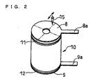
- FIG. 2 is a schematic perspective view of the electrode structure.
- the electrode structure is housed in a battery container 4 composed of a cylindrical battery can 5 having a bottom and also serving as a negative electrode terminal, and a battery cover 6 also serving as a positive electrode terminal.
- the electrode structure is composed of a columnar electrode group 10 formed by winding a laminate of a positive electrode 1, a negative electrode 2, and a separator 3 disposed between the positive electrode 1 and the negative electrode 2, a disc-shaped positive electrode current collector plate 8 electrically connected to the positive electrode 1, and a disc-shaped negative electrode current collector plate 9 electrically connected to the negative electrode 2.
- the positive electrode current collector plate 8 and the negative electrode current collector plate 9 are both disposed so as to cover planes (flat portions 11a and 12a that will be described below) substantially perpendicular to the winding axis of the electrode group 10.
- separators 3 are disposed on the outermost circumference side and on the innermost circumference side of the electrode group.
- a positive electrode connector piece 8a is connected to the positive electrode current collector plate 8, and the other end of the positive electrode connector piece 8a is connected to the bottom surface of the battery cover 6.
- the positive electrode 1 is electrically connected to the battery cover 6.
- One end of a negative electrode connector piece 9a is connected to the negative electrode current collector plate 9, and the other end of the negative electrode connector piece 9a is connected to the inner bottom surface of the battery can 5.
- the negative electrode 2 is electrically connected to the battery can 5.
- the end portion of the opening of the battery can 5 is crimped onto the peripheral edge of the battery cover 6 with a ring-shaped resin sealing body 7 interposed therebetween, and thereby the electrode structure is housed in the battery container 4 in a hermetically sealed manner.
- the positive electrode 1 is composed of a positive electrode current collector 1b made of aluminum foil, and positive electrode active material layers 1a formed on both sides of the positive electrode current collector 1b.
- the positive electrode active material layer 1a may be composed of, for example, a mixture of a positive electrode active material, a conductive material, and a binder.
- a lithium-containing composite oxide such as LiNiO 2 , LiCoO 2 , or LiMn 2 O 4 may be used as the positive electrode active material. It is also possible to use an oxide in which Ni, Co, or Mn in such oxides is partially substituted with another transition metal.
- a carbon material such as acetylene black may be used as the conductive material.
- polyvinylidene fluoride may be used as the binder.
- the positive electrode 1 has, at one end edge of the positive electrode 1 extending in the longitudinal direction of the laminate (the upper end edge of the positive electrode 1 in FIG. 1 ), portion where the positive electrode active material layer 1a is not formed, that is, a portion where the positive electrode current collector 1b is exposed (positive electrode current collector-exposed portion 11).
- the positive electrode current collector-exposed portion 11 protrudes upward beyond the negative electrode 2 along the winding axis, and the end edge of the positive electrode current collector-exposed portion 11 is bent in a direction substantially perpendicular to the winding axis and inward toward the center of the axis, thus forming a flat portion 11a, which will be a portion welded to the positive electrode current collector plate 8 as described below.
- the positive electrode current collector plate 8 is welded to the end edge (flat portion 11a) of the positive electrode current collector-exposed portion 11 to which a non-corrosive flux containing a fluoride is applied, whereby the positive electrode current collector plate 8 is electrically connected to the positive electrode 1.
- a flux is used as a fusing agent for welding for the purpose of removing an oxide film formed on the metal surface of a welded portion and preventing the formation of such an oxide film.
- An oxide film on the surface of aluminum foil is dissolved and removed by the flux that has been melted by heating during welding. This significantly improves the wettability of the molten metal from the current collector plate to the aluminum foil, and can thus achieve a favorable welding state between the positive electrode current collector plate and the flat portion of the positive electrode current collector-exposed portion, making it possible to provide a welding area and welding strength that are sufficient to attain a good state of bonding of the positive electrode current collector plate to the positive electrode.
- a corrosive flux for example, a flux containing a chloride
- the present invention since it is not necessary to use a brazing material for welding the positive electrode current collector plate and the positive electrode current collector-exposed portion, the components contained in a brazing material will not adversely affect the battery, making it possible to provide a highly reliable battery.
- the fluoride may contain, for example, aluminum, potassium, or cesium. It is preferable that the fluoride contains aluminum and potassium because of their excellent non-corrosive properties and non-hygroscopic properties.
- the fluoride include KAIF 4 , K 2 AIF 5 , K 3 AIF 6 , AIF 3 , KF, and CsF These may be used singly or in combination of two or more.
- the non-corrosive flux include a flux containing AIF 3 and KF, a flux containing KAIF 4 and K 3 AIF 6 , and a flux containing KF,AIF 3 , and Al 2 O3.
- the amount of "NOCOLOK” applied to the positive electrode current collector-exposed portion may be 0.1 to 0.3 g/cm 2 , for example.
- "NOCOLOK” is a flux having a eutectic composition of KF and AIF 3 , and has a eutectic point of 560 to 570°C. Therefore, when an aluminum plate is used as the positive electrode current collector plate, the temperature at which the positive electrode current collector plate is welded to the flat portion of the positive electrode current collector-exposed portion is preferably 570 to 660°C.
- the negative electrode 2 is composed of a negative electrode current collector 2b and negative electrode active material layers 2a formed on both sides of the negative electrode current collector 2b.
- copper foil may be used as the negative electrode current collector 2b.
- the negative electrode active material layer 2a may be composed of, for example, a mixture of a negative electrode active material, a conductive material, and a binder.
- a carbonaceous material such as graphite, petroleum coke, or carbon fiber, or a metal or oxide capable of absorbing and desorbing lithium may be used as the negative electrode active material.
- a carbon material such as artificial graphite may be used as the conductive material.
- polyvinylidene fluoride may be used as the binder.
- the negative electrode 2 has, at the other end edge of the negative electrode 2 extending in the longitudinal direction of the laminate (the lower end edge in FIG. 1 ), portion where the negative electrode active material layer 2a is not formed, that is, a portion where the negative electrode current collector 2b is exposed (negative electrode current collector-exposed portion 12).
- the negative electrode current collector-exposed portion 12 protrudes downward beyond the positive electrode 1 along the winding axis, and the end edge of the negative electrode current collector-exposed portion 12 is bent in a direction substantially perpendicular to the winding axis and inward toward the center of the axis, thus forming a flat portion 12a, which will be a portion welded to the negative electrode current collector plate 9.
- the negative electrode current collector plate 9 is welded to the flat portion 12a of the negative electrode current collector-exposed portion 12, whereby the negative electrode current collector plate 9 is electrically connected to the negative electrode 2.
- the electrode group 10 includes an electrolyte.
- the electrolyte is composed of a non-aqueous solvent and a lithium salt dissolved in the non-aqueous solvent.
- ethylene carbonate, propylene carbonate, dimethyl carbonate, or ethylmethyl carbonate may be used as the non-aqueous solvent.
- lithium hexafluorophosphate, lithium perchlorate, or lithium tetrafluoroborate may be used as the lithium salt.
- a slurry prepared by dispersing a flux in water is applied to the end edge (the portion where the flat portion 11a is to be formed) of the positive electrode current collector-exposed portion 11.
- water is removed by thermal drying to form a flux-coated layer on the end edge of the positive electrode current collector-exposed portion.
- a flux-coated layer may be formed by applying the above-described slurry to the flat portion 11a after forming the flat portion 11a.
- An appropriate amount of a binder such as carboxymethyl cellulose, polyethylene oxide, polyacrylic add, or starch may be further added to the above-described slurry.
- a slurry prepared by dispersing a flux in an organic solvent include aliphatic hydrocarbons such as hexane and aromatic hydrocarbons such as toluene.
- An appropriate amount of a binder such as polyvinyl butyral, polyvinyl pyrrolidone, or polystyrene may be further added to such a slurry.
- the positive electrode 1, the negative electrode 2, and the separator 3 are laminated in such a manner that the separator 3 is disposed between the positive electrode 1 and the negative electrode 2, the positive electrode current collector-exposed portion 11 protrudes beyond the negative electrode 2, and the negative electrode current collector-exposed portion 12 protrudes beyond the positive electrode 1, to form a laminate, which is further wound to yield an electrode group 10.
- the electrode group 10 is inserted into a cylindrical molding tool having a bottom, the electrode group 10 is pressed in the direction of the winding axis from the opening of the molding tool using a specific pressing tool.
- the end edges of the positive electrode current collector-exposed portion 11 and the negative electrode current collector exposed portion 12 are elastically deformed so as to be bent, thus forming flat portions 11 and 12a. Since the positive electrode 1 and the negative electrode 2 are wound, the positive and negative electrode current collector-exposed portions 11 and 12 are bent inward.
- the positive electrode current collector plate 8 is abutted on the flat portion 11a having a flux-coated layer formed on the surface thereof.
- the positive electrode current collector plate 8 is heated using a non-contact heat source from the surface opposite the surface thereof abutting on the flat portion 11a.
- a non-contact heat source examples include arc welding such as TIG welding, laser beam welding, and electron beam welding.
- the negative electrode current collector plate 9 is welded to the flat portion 12a of the negative electrode current collector-exposed portion 12 in the same manner as in the case where the positive electrode current collector plate 8 is welded to the flat portion 11a of the positive electrode current collector-exposed portion 11.
- the flux is applied to the surface of the positive electrode current collector-exposed portion abutting on the positive electrode current collector plate.
- the flux may be applied to the surface of the positive electrode current collector plate abutting on the positive electrode current collector-exposed portion, or the flux may be applied to both of the surface of the positive electrode current collector-exposed portion abutting on the positive electrode current collector plate and the surface of the positive electrode current collector plate abutting on the positive electrode current collector-exposed portion.
- a cylindrical lithium secondary battery having the structure shown in FIG. 1 as described above was produced in the following manner.
- Lithium cobaltate powder (average particle diameter of 10 ⁇ m) as a positive electrode active material, acetylene black (average particle diameter of 35 ⁇ m) as a conductive material, polyvinylidene fluoride (hereinafter, referred to as "PVDF") as a binder were mixed in a weight ratio of 85:10:5 to yield a positive electrode mixture.
- PVDF polyvinylidene fluoride
- This positive electrode mixture was applied to both sides of a 15 ⁇ m-thick, 56 mm-wide strip-shaped positive electrode current collector 1b made of aluminum foil, and then dried to form a positive electrode active material layer 1a. At this time, a portion where the positive electrode mixture was not applied (current collector-exposed portion 11) was provided at one widthwise end of the positive electrode current collector 1b.
- the portion where the positive electrode mixture was applied was rolled to produce a 100 ⁇ m-thick strip-shaped positive electrode 1.
- the width of the positive electrode mixture-coated portion was 50 mm, and the width of the positive electrode mixture-uncoated portion (current collector-exposed portion 11) was 6 mm.
- a slurry prepared by dispersing a non-corrosive flux ("NOCOLOK” (registered trademark), manufactured by Rio Tinto Alcan Inc.) in water was applied to a portion of the end edge of the current collector-exposed portions 11 extending from the end edge in a width of 1 mm of the width (6 mm) of the positive electrode mixture-uncoated portion (current collector-exposed portion 11), and then heated at 100°C for 5 minutes to remove water.
- NOCOLOK non-corrosive flux
- a strip-shaped separator 3 (having a width of 53 mm and a thickness of 25 ⁇ m) made of a microporous polypropylene resin film was disposed between the positive electrode mixture-coated portion and the negative electrode mixture-coated portion. Thereafter, the positive electrode, the negative electrode, and the separator were spirally wound to produce an electrode group 10. At this time, separators 3 were also disposed on the outermost circumference side and on the innermost circumference side of the electrode group 10.
- a 50 mm-square aluminum plate (A1050) (thickness of 1 mm) was pressed into a disc with a diameter of 24 mm to give a positive electrode current collector plate 8.
- a hole with a diameter of 7 mm was formed in the center of the aluminum disk.
- a 50 mm-square copper plate (C1020) (thickness of 0.6 mm) was pressed into a disc with a diameter of 24 mm to give a negative electrode current collector plate 9.
- the electrode group 10 was inserted into a specific cylindrical molding tool having a bottom, and then pressed by a specific pressing tool from the opening of the molding tool. At this time, the end edges of the current collector-exposed portions 11 and 12 of the positive and negative electrodes were bent inward, and thereby flat portions 11a and 12a were formed.
- the positive electrode current collector plate 8 was abutted on the flat portion 11a of the current collector-exposed portion 11 where the flux-coated layer was formed, and the positive electrode current collector plate was TIG-welded to the flat portion 11a of the positive electrode current collector-exposed portion 11. More specifically, as shown in FIG.
- an arc welding machine (a full digital AC/DC TIG welding machine 300BP2, manufactured by Panasonic Welding Systems Co., Ltd.) as a non-contact heat source 15
- an arc was applied to the upper surface of the positive electrode current collector plate 8 while moving the non-contact heat source 15 radially from above the positive electrode current collector plate 8 (from above the surface opposite the surface abutting on the positive electrode current collector-exposed portion 11).
- the conditions of the TIG welding for the positive electrode 1 side were a current value of 150 A and a welding time of 100 ms.
- the negative electrode current collector plate 9 was abutted on the flat portion 12a of the current collector-exposed portion 12 of the negative electrode 2, and the flat portion 12a of the negative electrode current collector-exposed portion 12 was TIG-welded to the negative electrode current collector plate 9 in the same manner as described above.
- the conditions of the TIG welding for the negative electrode 2 side were a current value of 200A and a welding time of 50 ms. Thus, an electrode structure was produced.
- One end of the aluminum positive electrode connector piece 8a was laser-welded to the positive electrode current collector plate 8 of the electrode structure.
- One end of the copper negative electrode connector piece 9a was laser-welded to the negative electrode current collector plate 9 of the electrode structure. Thereafter, the electrode structure was housed in the cylindrical battery can 5 having a bottom, and then the other end of the negative electrode connector piece 9a was resistance-welded to the inner bottom surface of the battery can 5. The other end of the positive electrode connector piece 8a was laser-welded to the battery cover 6.
- the battery can 5 was dried by heating, and a non-aqueous electrolyte was then injected into the battery can 5.
- a non-aqueous electrolyte prepared by dissolving lithium hexafluorophosphate (LiPF 6 ) in a mixed solvent of ethylene carbonate and ethylmethyl carbonate (volume ratio 1:1) was used. Thereafter, the peripheral edge of the battery cover 6 was crimped to the end of the opening of the battery can 5 with the resin sealing body 7 disposed therebetween.
- the electrode structure was housed in a hermetically sealed manner in the battery container 4 composed of the battery can 5 and the battery cover 6 to produce a cylindrical lithium ion secondary battery (battery capacity of 2600 mAh) with a diameter of 26 mm and a height of 65 mm.
- a cylindrical lithium secondary battery was produced in the same manner as in Example 1 except that the non-corrosive flux was not applied to the positive electrode current colledor-exposed portion.
- Example 1 Five pieces of each battery of Example 1 and Comparative Example 1 were provided.
- the electrode group and the positive electrode current collector plate were pulled in the axial directions of the tensile tester (the directions in which the electrode group and the current collector plate moved away from each other) at a constant speed, and the load with which the welded portion failed and the positive electrode current collector plate was separated from the portion where it was bonded to the electrode group was regarded as a tensile strength.
- All of the batteries of Example 1 had a tensile strength of 70 N or greater.
- three of the five batteries of Comparative Example 1 had a tensile strength of 20 N or less, and the welded portion failed.
- Example 1 Fifty pieces of each battery of Example 1 and Comparative Example 1 were provided. Each battery was subjected to three repeated charge/discharge cycles in each of which the battery was charged with a constant current of 1250 mA until the dosed-circuit voltage reached 4.2 V and then discharged with a constant current of 1250 mA until the dosed-circuit voltage reached 3.0 V Thereafter, an alternating current of 1 kHz was applied to each battery to measure the internal resistance. Then, the average value for and the variation in the internal resistance were determined. The ratio of the maximum value (absolute value) of the difference between a measured value and the average value relative to the average value was used as the variation. For the batteries of Example 1, the average value of the intemal resistance was 5 m ⁇ , and the variation was 10%. On the other hand, for the batteries of Comparative Example 1, the average value of the internal resistance was 11 m ⁇ , and the variation was 20%.
- the average value of the output currents of the batteries of Example 1 was 540 A, whereas that of the batteries of Comparative Example 1 was 245 A. This showed that the batteries of Example 1 can be discharged with a larger current than the batteries of Comparative Example 1.
- Example 1 Three pieces of each battery of Example 1 and Comparative Example 1 were provided. Each battery was subjected to a vibration test in accordance with JIS D 1601. None of the batteries of Example 1 showed any change in voltage before and after the test, and the inspection of the interior after disassembling the batteries did not show any abnormality. On the other hand, two of the three batteries of Comparative Example 1 showed a voltage of 0 volt after the test. As a result of disassembling these batteries and inspecting the interior thereof, it was confirmed that the portion where the positive electrode current collector plate and the positive electrode current collector-exposed portion had been welded to each other failed.
- the lithium ion secondary battery of the present invention can be suitably used as a power source of electronic devices requiring high output, such as portable devices.
Landscapes
- Chemical & Material Sciences (AREA)
- Engineering & Computer Science (AREA)
- Manufacturing & Machinery (AREA)
- Chemical Kinetics & Catalysis (AREA)
- Electrochemistry (AREA)
- General Chemical & Material Sciences (AREA)
- Materials Engineering (AREA)
- Secondary Cells (AREA)
- Cell Electrode Carriers And Collectors (AREA)
- Connection Of Batteries Or Terminals (AREA)
Abstract
A lithium ion secondary battery of the invention includes an electrode structure induding an electrode group composed of a strip-shaped laminate or winding induding a positive electrode in which a positive electrode active material layer is attached to a positive electrode current collector, a negative electrode, and a separator, a positive electrode current collector plate induding aluminum foil; and a negative electrode current collector plate electrically connected to the negative electrode. The positive electrode has, at one longitudinally extending end edge of the laminate, a positive electrode current collector-exposed portion protruding beyond the negative electrode. The positive electrode current collector plate is electrically connected to the positive electrode by applying a non-corrosive flux containing a fluoride to at least one of the positive electrode current collector-exposed portion and the positive electrode current collector plate, and then welding the positive electrode current collector plate to the positive electrode current collector-exposed portion.
Description
- The present invention relates to a lithium ion secondary battery having a tabless structure in which current collector plates are welded to current collector-exposed portions provided at end edges of electrodes, and a method for produdng the same.
- In order to increase the output of a lithium ion secondary battery, a method has been used in which the current collecting structure of the electrode group of the lithium ion secondary battery is configured as a tabless structure. The tabless structure is described below. An electrode group is formed by winding a laminate induding a positive electrode composed of a positive electrode current collector and a positive electrode active material layer attached to the positive electrode current collector, a negative electrode composed of a negative electrode current collector and a negative electrode active material layer attached to the negative electrode current collector, and a separator disposed between the positive electrode and the negative electrode. The positive electrode has, at one longitudinally extending end edge of the laminate, a portion where the positive electrode current collector is exposed (positive electrode current collector-exposed porfion). The negative electrode has, at the other longitudinally extending end edge of the laminate, a portion where the negative electrode current collector is exposed (negative electrode current collector-exposed portion). The positive electrode current collector plate is welded to the positive electrode current collector-exposed portion, whereby the positive electrode is electrically connected to the positive electrode current collector plate. The negative electrode current collector plate is welded to the negative electrode current collector-exposed portion, whereby the negative electrode is electrically connected to the negative electrode current collector plate. Consequently, a current collection path is ensured for the strip-shaped electrodes.
- Further improvements for the tabless structure have been investigated. For example,
Patent Document 1 proposes providing a current collector plate with a portion into which a current collector-exposed portion can bite, and welding the current collector plate to the current collector-exposed portion with a part of the current collector-exposed portion biting into that portion to achieve improved contact between the current collector plate and the electrode. However, since aluminum foil is used as the positive electrode current collector of lithium ion secondary batteries, the positive electrode current collector-exposed portion cannot be easily wetted by the molten metal from the positive electrode current collector plate at the time of welding, making it difficult to achieve good bonding. Consequently, the bonding area and the bonding strength between the positive electrode current collector-exposed portion and the positive electrode current collector plate cannot be provided sufficiently, which may result in deteriorated output characteristics of the battery and reduced reliability against vibrations and falling. -
Patent Document 2 proposes applying a brazing material to a current collector plate in advance, abutting the surface of the current collector plate to which the brazing material has been applied on a current collector-exposed portion, and welding the current collector plate to the electrode at this abutment portion to reliably bond the current collector plate to the current collector-exposed portion made of aluminum foil. However, metal components contained in the brazing material other than aluminum may be mixed in the welded portion at the time of welding, and these components may further enter into the battery structure, adversely affecting the battery characteristics. - Patent Document 1: Japanese Patent No.
3738166 - Patent Document 2: Japanese Laid-Open Patent Publication No.
2001-93505 - Therefore, it is an object of the present invention to provide a highly reliable lithium ion secondary battery having excellent output characteristics, and a method for producing the same in order to solve the above-described conventional problems.
- A lithium ion secondary battery according to the present invention includes:
- an electrode structure induding an electrode group including a laminate or a winding of a strip-shaped positive electrode in which a positive electrode active material layer is attached to a positive electrode current collector, a strip-shaped negative electrode in which a negative electrode active material layer is attached to a negative electrode current collector, and a strip-shaped porous insulating material disposed between the positive electrode and the negative electrode; a positive electrode current collector plate; and a negative electrode current collector plate electrically connected to the negative electrode; and
- a battery container housing the electrode structure,
- wherein the positive electrode current collector is aluminum foil,
- the positive electrode has, at one longitudinally extending end edge of the laminate, a positive electrode current collector-exposed portion protruding beyond the negative electrode, and
- the positive electrode current collector plate is electrically connected to the positive electrode by applying a non-corrosive flux induding a fluoride to at least one of the positive electrode current collector-exposed portion and the positive electrode current collector plate, and then welding the positive electrode current collector plate to the positive electrode current collector-exposed portion.
- Preferably, the negative electrode has, at the other longitudinally extending end edge of the laminate, a negative electrode current collector-exposed portion protruding beyond the positive electrode, and the negative electrode current collector plate is welded to the negative electrode current collector-exposed portion.
Preferably, the positive electrode current collector plate is an aluminum plate. - Furthermore, the present invention relates to a method for producing a lithium ion secondary battery induding the steps of:
- (1) laminating or winding a strip-shaped positive electrode in which a positive electrode active material layer is attached to a positive electrode current collector induding aluminum foil and having a positive electrode current collector-exposed portion at one longitudinally extending end edge thereof, a strip-shaped negative electrode in which a negative electrode active material layer is attached to a negative electrode current collector, and a strip-shaped porous insulating material, in such a manner that the porous insulating material is disposed between the positive electrode and the negative electrode, and the positive electrode current collector-exposed portion protrudes beyond the negative electrode, to obtain an electrode group;
- (2) applying a non-corrosive flux induding a fluoride to at least one of the positive electrode current collector-exposed portion and a positive electrode current collector plate;
- (3) welding, after the step (2), the positive electrode current collector plate to the positive electrode current collector-exposed portion, thereby electrically connecting the positive electrode current collector plate to the positive electrode;
- (4) electrically connecting a negative electrode current collector plate to the negative electrode; and
- (5) housing, in a battery container, an electrode structure induding the electrode group, and the positive electrode current collector plate and the negative electrode current collector plate respectively welded to the electrode group.
- Preferably, the negative electrode has a negative electrode current collector-exposed portion at one longitudinally extending end edge thereof; in the step (1), the positive electrode, the negative electrode, and the porous insulating material are laminated or wound in such a manner that the negative electrode current collector-exposed portion protrudes beyond the positive electrode; and, in the step (4), the negative electrode current collector plate is welded to the negative electrode current collector-exposed portion.
Preferably, the positive electrode current collector plate is an aluminum plate. - The present invention can provide a highly reliable lithium ion secondary battery having excellent output characteristics, and a method for produdng the same.
-
-
FIG. 1 is a schematic vertical cross-sectional view of a lithium ion secondary battery according to one embodiment of the present invention. -
FIG. 2 is a perspective view of the electrode structure shown inFIG. 1 . - The present invention relates to a lithium ion secondary battery including: an electrode structure induding an electrode group induding a laminate or a winding of a strip-shaped positive electrode in which a positive electrode active material layer is attached to a positive electrode current collector, a strip-shaped negative electrode in which a negative electrode active material layer is attached to a negative electrode current collector, and a strip-shaped porous insulating material disposed between the positive electrode and the negative electrode; a positive electrode current collector plate; and a negative electrode current collector plate electrically connected to the negative electrode; and a battery container housing the electrode structure. The invention is characterized in that the positive electrode current collector is aluminum foil, the positive electrode has, at one longitudinally extending end edge of the laminate, a positive electrode current collector exposed portion protruding beyond the negative electrode, and the positive electrode current collector plate is electrically connected to the positive electrode, by applying a non-corrosive flux induding a fluoride to at least one of the positive electrode current collector-exposed portion and the positive electrode current collector plate, and then welding the positive electrode current collector plate to the positive electrode current collector-exposed portion.
This ensures good contact between the positive electrode for which aluminum foil is used as the positive electrode current collector and the positive electrode current collector plate, thus yielding a highly reliable lithium ion secondary battery having excellent output characteristics.
When the electrode group is a winding, this positive electrode current collector plate is disposed so as to cover a plane substantially perpendicular to the winding axis of the electrode group. The non-corrosive flux is applied to at least one of the portion of the positive electrode current collector exposed portion that is welded to the positive electrode current collector plate and the portion of the positive electrode current collector plate that is welded to the positive electrode current collector-exposed portion. - An example of the current collecting structure on the negative electrode side (the form of connection between the negative electrode and the negative electrode current collector plate) described above is the same structure (tabless structure) as that on the positive electrode side. Specifically the above-described negative electrode has, at the other longitudinally extending end edge of the laminate, a negative electrode current collector-exposed portion protruding beyond the positive electrode, and the negative electrode current collector plate is welded to the negative electrode current collector-exposed portion. When the electrode group is a winding, this negative electrode current collector plate is disposed so as to cover a plane substantially perpendicular to the winding axis of the electrode group.
Alternatively, a lead-shaped negative electrode current collector plate may be used as the negative electrode current collector plate. Specifically, the strip-shaped negative electrode may have a structure such that it has a negative electrode current collector-exposed portion along one widthwise end edge, and the lead-shaped negative electrode current collector plate is welded to the negative electrode current collector-exposed portion. The lead-shaped negative electrode current collector plate is disposed in the width direction of the negative electrode (along the winding axis of the electrode group). - The thickness of the aluminum foil used as the positive electrode current collector may be 10 to 30 µm, for example.
To achieve excellent current collection capability and chemical stability under use conditions of lithium ion secondary batteries, it is preferable to use an aluminum plate as the positive electrode current collector plate. The thickness of the aluminum plate may be 0.3 to 1 mm, for example. - A method for producing a lithium ion secondary battery according to the present invention includes the steps of:
- (1) laminating or winding a strip-shaped positive electrode in which a positive electrode active material layer is attached to a positive electrode current collector induding aluminum foil and having a positive electrode current collector-exposed portion at one longitudinally extending end edge thereof, a strip-shaped negative electrode in which a negative electrode active material layer is attached to a negative electrode current collector, and a strip-shaped porous insulating material, in such a manner that the porous insulating material is disposed between the positive electrode and the negative electrode, and the positive electrode current collector-exposed portion protrudes beyond the negative electrode, to obtain an electrode group;
- (2) applying a non-corrosive flux induding a fluoride to at least one of the positive electrode current collector-exposed portion and a positive electrode current collector plate;
- (3) welding, after the step (2), the positive electrode current collector plate to the positive electrode current collector-exposed portion, thereby electrically connecting the positive electrode current collector plate to the positive electrode;
- (4) electrically connecting a negative electrode current collector plate to the negative electrode; and
- (5) housing, in a battery container, an electrode structure induding the electrode group, and the positive electrode current collector plate and the negative electrode current collector plate respectively welded to the electrode group.
- When the negative electrode has the same structure as that of the positive electrode (a structure corresponding to the tabless structure), or in other words, when the negative electrode has a negative electrode current collector-exposed portion at one longitudinally extending end edge thereof, the positive electrode, the negative electrode, and the separator are laminated or wound in such a manner that the negative electrode current collector-exposed portion protrudes beyond the positive electrode in the step (1), and the negative electrode current collector plate is welded to the negative electrode current collector-exposed portion in the step (4).
An example of forming a laminate is a method in which a separator made of a porous resin film is disposed between the positive electrode and the negative electrode as an insulating material at the time of forming the laminate. Another example is a method in which a porous resin layer is formed as an insulating material on one of the positive electrode and the negative electrode prior to the lamination, and one of the positive electrode and the negative electrode on which the porous resin layer is formed is laminated on the other of the positive electrode and the negative electrode. - Hereinafter, one embodiment of the lithium ion secondary battery according to the present invention is described with reference to
FIGS. 1 and2 .FIG. 1 is a schematic vertical cross-sectional view of a cylindrical lithium secondary battery.FIG. 2 is a schematic perspective view of the electrode structure.
As shown inFIG.1 , the electrode structure is housed in a battery container 4 composed of a cylindrical battery can 5 having a bottom and also serving as a negative electrode terminal, and abattery cover 6 also serving as a positive electrode terminal. The electrode structure is composed of a columnar electrode group 10 formed by winding a laminate of apositive electrode 1, anegative electrode 2, and a separator 3 disposed between thepositive electrode 1 and thenegative electrode 2, a disc-shaped positive electrodecurrent collector plate 8 electrically connected to thepositive electrode 1, and a disc-shaped negative electrodecurrent collector plate 9 electrically connected to thenegative electrode 2. The positive electrodecurrent collector plate 8 and the negative electrodecurrent collector plate 9 are both disposed so as to cover planes (flat portions - One end of a positive
electrode connector piece 8a is connected to the positive electrodecurrent collector plate 8, and the other end of the positiveelectrode connector piece 8a is connected to the bottom surface of thebattery cover 6. Thereby, thepositive electrode 1 is electrically connected to thebattery cover 6. One end of a negativeelectrode connector piece 9a is connected to the negative electrodecurrent collector plate 9, and the other end of the negativeelectrode connector piece 9a is connected to the inner bottom surface of the battery can 5. Thereby, thenegative electrode 2 is electrically connected to the battery can 5. The end portion of the opening of the battery can 5 is crimped onto the peripheral edge of thebattery cover 6 with a ring-shaped resin sealing body 7 interposed therebetween, and thereby the electrode structure is housed in the battery container 4 in a hermetically sealed manner. - The
positive electrode 1 is composed of a positive electrode current collector 1b made of aluminum foil, and positive electrode active material layers 1a formed on both sides of the positive electrode current collector 1b. The positive electrode active material layer 1a may be composed of, for example, a mixture of a positive electrode active material, a conductive material, and a binder. For example, a lithium-containing composite oxide such as LiNiO2, LiCoO2, or LiMn2O4 may be used as the positive electrode active material. It is also possible to use an oxide in which Ni, Co, or Mn in such oxides is partially substituted with another transition metal. For example, a carbon material such as acetylene black may be used as the conductive material. For example, polyvinylidene fluoride may be used as the binder. - The
positive electrode 1 has, at one end edge of thepositive electrode 1 extending in the longitudinal direction of the laminate (the upper end edge of thepositive electrode 1 inFIG. 1 ), portion where the positive electrode active material layer 1a is not formed, that is, a portion where the positive electrode current collector 1b is exposed (positive electrode current collector-exposed portion 11). The positive electrode current collector-exposedportion 11 protrudes upward beyond thenegative electrode 2 along the winding axis, and the end edge of the positive electrode current collector-exposedportion 11 is bent in a direction substantially perpendicular to the winding axis and inward toward the center of the axis, thus forming aflat portion 11a, which will be a portion welded to the positive electrodecurrent collector plate 8 as described below. The positive electrodecurrent collector plate 8 is welded to the end edge (flat portion 11a) of the positive electrode current collector-exposedportion 11 to which a non-corrosive flux containing a fluoride is applied, whereby the positive electrodecurrent collector plate 8 is electrically connected to thepositive electrode 1. - A flux is used as a fusing agent for welding for the purpose of removing an oxide film formed on the metal surface of a welded portion and preventing the formation of such an oxide film. An oxide film on the surface of aluminum foil is dissolved and removed by the flux that has been melted by heating during welding. This significantly improves the wettability of the molten metal from the current collector plate to the aluminum foil, and can thus achieve a favorable welding state between the positive electrode current collector plate and the flat portion of the positive electrode current collector-exposed portion, making it possible to provide a welding area and welding strength that are sufficient to attain a good state of bonding of the positive electrode current collector plate to the positive electrode.
When a corrosive flux (for example, a flux containing a chloride) is used, it is necessary to perform a treatment to remove the remaining flux components after welding for the purpose of preventing corrosion of the welded portion. However, according to the present invention, it is not necessary to remove the remaining flux components since the present invention uses a non-corrosive flux.
According to the present invention, since it is not necessary to use a brazing material for welding the positive electrode current collector plate and the positive electrode current collector-exposed portion, the components contained in a brazing material will not adversely affect the battery, making it possible to provide a highly reliable battery. - The fluoride may contain, for example, aluminum, potassium, or cesium. It is preferable that the fluoride contains aluminum and potassium because of their excellent non-corrosive properties and non-hygroscopic properties. Examples of the fluoride include KAIF4, K2AIF5, K3AIF6, AIF3, KF, and CsF These may be used singly or in combination of two or more. Examples of the non-corrosive flux include a flux containing AIF3 and KF, a flux containing KAIF4 and K3AIF6, and a flux containing KF,AIF3, and Al2O3.
- It is preferable to use "NOCOLOK" (registered trademark) as the flux. The amount of "NOCOLOK" applied to the positive electrode current collector-exposed portion may be 0.1 to 0.3 g/cm2, for example. "NOCOLOK" is a flux having a eutectic composition of KF and AIF3, and has a eutectic point of 560 to 570°C. Therefore, when an aluminum plate is used as the positive electrode current collector plate, the temperature at which the positive electrode current collector plate is welded to the flat portion of the positive electrode current collector-exposed portion is preferably 570 to 660°C.
Although the flux remains on the surface of the portion where the positive electrode and the positive electrode current collector plate are welded to each other, the flux will not adversely affect the battery characteristics since it is non-corrosive. "NOCOLOK" has excellent corrosion resistance, and therefore "NOCOLOK" remaining on the surface improves the corrosion resistance of the portion where the positive electrode current collector plate and the flat portion of the positive electrode current collector-exposed portion are welded to each other. - The
negative electrode 2 is composed of a negative electrode current collector 2b and negative electrodeactive material layers 2a formed on both sides of the negative electrode current collector 2b. For example, copper foil may be used as the negative electrode current collector 2b. The negative electrodeactive material layer 2a may be composed of, for example, a mixture of a negative electrode active material, a conductive material, and a binder. For example, a carbonaceous material such as graphite, petroleum coke, or carbon fiber, or a metal or oxide capable of absorbing and desorbing lithium may be used as the negative electrode active material. For example, a carbon material such as artificial graphite may be used as the conductive material. For example, polyvinylidene fluoride may be used as the binder. - The
negative electrode 2 has, at the other end edge of thenegative electrode 2 extending in the longitudinal direction of the laminate (the lower end edge inFIG. 1 ), portion where the negative electrodeactive material layer 2a is not formed, that is, a portion where the negative electrode current collector 2b is exposed (negative electrode current collector-exposed portion 12). The negative electrode current collector-exposedportion 12 protrudes downward beyond thepositive electrode 1 along the winding axis, and the end edge of the negative electrode current collector-exposedportion 12 is bent in a direction substantially perpendicular to the winding axis and inward toward the center of the axis, thus forming aflat portion 12a, which will be a portion welded to the negative electrodecurrent collector plate 9. The negative electrodecurrent collector plate 9 is welded to theflat portion 12a of the negative electrode current collector-exposedportion 12, whereby the negative electrodecurrent collector plate 9 is electrically connected to thenegative electrode 2. - For example, a microporous film made of polyethylene or polypropylene may be used as the separator 3.
The electrode group 10 includes an electrolyte. The electrolyte is composed of a non-aqueous solvent and a lithium salt dissolved in the non-aqueous solvent. For example, ethylene carbonate, propylene carbonate, dimethyl carbonate, or ethylmethyl carbonate may be used as the non-aqueous solvent. For example, lithium hexafluorophosphate, lithium perchlorate, or lithium tetrafluoroborate may be used as the lithium salt. - Hereinafter, a description is given of a specific example of a production method of an electrode structure composed of the electrode group 10, the positive electrode
current collector plate 8, and the negative electrodecurrent collector plate 9.
Before forming a laminate (before forming theflat portion 11a), a slurry prepared by dispersing a flux in water is applied to the end edge (the portion where theflat portion 11a is to be formed) of the positive electrode current collector-exposedportion 11. Thereafter, water is removed by thermal drying to form a flux-coated layer on the end edge of the positive electrode current collector-exposed portion. Alternatively a flux-coated layer may be formed by applying the above-described slurry to theflat portion 11a after forming theflat portion 11a.
An appropriate amount of a binder such as carboxymethyl cellulose, polyethylene oxide, polyacrylic add, or starch may be further added to the above-described slurry.
Apart from the above-described slurry, it is possible to use a slurry prepared by dispersing a flux in an organic solvent. Examples of the organic solvent include aliphatic hydrocarbons such as hexane and aromatic hydrocarbons such as toluene. An appropriate amount of a binder such as polyvinyl butyral, polyvinyl pyrrolidone, or polystyrene may be further added to such a slurry. - The
positive electrode 1, thenegative electrode 2, and the separator 3 are laminated in such a manner that the separator 3 is disposed between thepositive electrode 1 and thenegative electrode 2, the positive electrode current collector-exposedportion 11 protrudes beyond thenegative electrode 2, and the negative electrode current collector-exposedportion 12 protrudes beyond thepositive electrode 1, to form a laminate, which is further wound to yield an electrode group 10. After the electrode group 10 is inserted into a cylindrical molding tool having a bottom, the electrode group 10 is pressed in the direction of the winding axis from the opening of the molding tool using a specific pressing tool. At this time, the end edges of the positive electrode current collector-exposedportion 11 and the negative electrode current collector exposedportion 12 are elastically deformed so as to be bent, thus formingflat portions positive electrode 1 and thenegative electrode 2 are wound, the positive and negative electrode current collector-exposedportions - The positive electrode
current collector plate 8 is abutted on theflat portion 11a having a flux-coated layer formed on the surface thereof. The positive electrodecurrent collector plate 8 is heated using a non-contact heat source from the surface opposite the surface thereof abutting on theflat portion 11a. Thus, the positive electrodecurrent collector plate 8 is welded to theflat portion 11a of the positive electrode current collector-exposedportion 11. Examples of welding using a non-contact heat source include arc welding such as TIG welding, laser beam welding, and electron beam welding. In terms of working efficiency and uniform current collection, it is preferable that welding is performed while moving anon-contact heat source 15 radially from above the disc-shaped positive electrode current collector plate 8 (from above the surface opposite the surface abutting on the positive electrode current collector-exposed portion 11) as shown inFIG. 2 . The negative electrodecurrent collector plate 9 is welded to theflat portion 12a of the negative electrode current collector-exposedportion 12 in the same manner as in the case where the positive electrodecurrent collector plate 8 is welded to theflat portion 11a of the positive electrode current collector-exposedportion 11.
In the above-described embodiment, a case was described where the flux is applied to the surface of the positive electrode current collector-exposed portion abutting on the positive electrode current collector plate. However, the flux may be applied to the surface of the positive electrode current collector plate abutting on the positive electrode current collector-exposed portion, or the flux may be applied to both of the surface of the positive electrode current collector-exposed portion abutting on the positive electrode current collector plate and the surface of the positive electrode current collector plate abutting on the positive electrode current collector-exposed portion. - Examples of the present invention will be described in detail below, but the invention is not limited to these examples.
- A cylindrical lithium secondary battery having the structure shown in
FIG. 1 as described above was produced in the following manner. - Lithium cobaltate powder (average particle diameter of 10 µm) as a positive electrode active material, acetylene black (average particle diameter of 35 µm) as a conductive material, polyvinylidene fluoride (hereinafter, referred to as "PVDF") as a binder were mixed in a weight ratio of 85:10:5 to yield a positive electrode mixture. This positive electrode mixture was applied to both sides of a 15 µm-thick, 56 mm-wide strip-shaped positive electrode current collector 1b made of aluminum foil, and then dried to form a positive electrode active material layer 1a. At this time, a portion where the positive electrode mixture was not applied (current collector-exposed portion 11) was provided at one widthwise end of the positive electrode current collector 1b. The portion where the positive electrode mixture was applied (positive electrode mixture-coated portion) was rolled to produce a 100 µm-thick strip-shaped
positive electrode 1. At this time, in the width direction of thepositive electrode 1, the width of the positive electrode mixture-coated portion was 50 mm, and the width of the positive electrode mixture-uncoated portion (current collector-exposed portion 11) was 6 mm. - A slurry prepared by dispersing a non-corrosive flux ("NOCOLOK" (registered trademark), manufactured by Rio Tinto Alcan Inc.) in water was applied to a portion of the end edge of the current collector-exposed
portions 11 extending from the end edge in a width of 1 mm of the width (6 mm) of the positive electrode mixture-uncoated portion (current collector-exposed portion 11), and then heated at 100°C for 5 minutes to remove water. Thus, a flux-coated layer was formed on the end edge of the positive electrode current collector-exposedportion 11. At this time, the amount of the flux applied was 0.2 g/crn2. - Artificial graphite powder (
average particle diameter 15 µm) as a negative electrode active material and PVDF as a binder were mixed in a weight ratio of 95:5 to yield a negative electrode mixture. This negative electrode mixture was applied to both sides of a 10 µm-thick, 57 mm-wide strip-shaped negative electrode current collector 2b made of copper foil, and then dried to form a negative electrodeactive material layer 2a. At this time, a portion where the negative electrode mixture was not applied (current collector-exposed portion 12) was provided at one widthwise end of the negative electrode current collector 2b. The portion where the negative electrode mixture was applied (negative electrode mixture-coated portion) was rolled to produce a 100 µm-thick strip-shapednegative electrode 2. At this time, in the width direction of thenegative electrode 2, the width of the negative electrode mixture-coated portion was 52 mm, and the width of the negative electrode mixture-uncoated portion (current collector-exposed portion 12) was 5 mm. - A strip-shaped separator 3 (having a width of 53 mm and a thickness of 25 µm) made of a microporous polypropylene resin film was disposed between the positive electrode mixture-coated portion and the negative electrode mixture-coated portion. Thereafter, the positive electrode, the negative electrode, and the separator were spirally wound to produce an electrode group 10. At this time, separators 3 were also disposed on the outermost circumference side and on the innermost circumference side of the electrode group 10.
- A 50 mm-square aluminum plate (A1050) (thickness of 1 mm) was pressed into a disc with a diameter of 24 mm to give a positive electrode
current collector plate 8. In addition, a hole with a diameter of 7 mm was formed in the center of the aluminum disk.
A 50 mm-square copper plate (C1020) (thickness of 0.6 mm) was pressed into a disc with a diameter of 24 mm to give a negative electrodecurrent collector plate 9. - The electrode group 10 was inserted into a specific cylindrical molding tool having a bottom, and then pressed by a specific pressing tool from the opening of the molding tool. At this time, the end edges of the current collector-exposed
portions flat portions
The positive electrodecurrent collector plate 8 was abutted on theflat portion 11a of the current collector-exposedportion 11 where the flux-coated layer was formed, and the positive electrode current collector plate was TIG-welded to theflat portion 11a of the positive electrode current collector-exposedportion 11. More specifically, as shown inFIG. 2 , using an arc welding machine (a full digital AC/DC TIG welding machine 300BP2, manufactured by Panasonic Welding Systems Co., Ltd.) as anon-contact heat source 15, an arc was applied to the upper surface of the positive electrodecurrent collector plate 8 while moving thenon-contact heat source 15 radially from above the positive electrode current collector plate 8 (from above the surface opposite the surface abutting on the positive electrode current collector-exposed portion 11). The conditions of the TIG welding for thepositive electrode 1 side were a current value of 150 A and a welding time of 100 ms. The negative electrodecurrent collector plate 9 was abutted on theflat portion 12a of the current collector-exposedportion 12 of thenegative electrode 2, and theflat portion 12a of the negative electrode current collector-exposedportion 12 was TIG-welded to the negative electrodecurrent collector plate 9 in the same manner as described above. The conditions of the TIG welding for thenegative electrode 2 side were a current value of 200A and a welding time of 50 ms. Thus, an electrode structure was produced. - One end of the aluminum positive
electrode connector piece 8a was laser-welded to the positive electrodecurrent collector plate 8 of the electrode structure. One end of the copper negativeelectrode connector piece 9a was laser-welded to the negative electrodecurrent collector plate 9 of the electrode structure. Thereafter, the electrode structure was housed in the cylindrical battery can 5 having a bottom, and then the other end of the negativeelectrode connector piece 9a was resistance-welded to the inner bottom surface of the battery can 5. The other end of the positiveelectrode connector piece 8a was laser-welded to thebattery cover 6. - Subsequently, the battery can 5 was dried by heating, and a non-aqueous electrolyte was then injected into the battery can 5. As the non-aqueous electrolyte, a non-aqueous electrolyte prepared by dissolving lithium hexafluorophosphate (LiPF6) in a mixed solvent of ethylene carbonate and ethylmethyl carbonate (volume ratio 1:1) was used. Thereafter, the peripheral edge of the
battery cover 6 was crimped to the end of the opening of the battery can 5 with the resin sealing body 7 disposed therebetween. Thus, the electrode structure was housed in a hermetically sealed manner in the battery container 4 composed of the battery can 5 and thebattery cover 6 to produce a cylindrical lithium ion secondary battery (battery capacity of 2600 mAh) with a diameter of 26 mm and a height of 65 mm. - A cylindrical lithium secondary battery was produced in the same manner as in Example 1 except that the non-corrosive flux was not applied to the positive electrode current colledor-exposed portion.
- Five pieces of each battery of Example 1 and Comparative Example 1 were provided. The tensile strength of the portion where the positive electrode current collector plate and the positive electrode are welded to each other of each battery was measured in accordance with JIS Z 2241. Specifically, while the electrode group was held on one side of a tensile tester (with a load cell SL-5001 and a displacement meter SL-1 00, manufactured by IMADA SEISAKUSHO CO., LTD.), the positive electrode current collector plate was held on the other side of the tensile tester. The electrode group and the positive electrode current collector plate were pulled in the axial directions of the tensile tester (the directions in which the electrode group and the current collector plate moved away from each other) at a constant speed, and the load with which the welded portion failed and the positive electrode current collector plate was separated from the portion where it was bonded to the electrode group was regarded as a tensile strength.
All of the batteries of Example 1 had a tensile strength of 70 N or greater. On the other hand, three of the five batteries of Comparative Example 1 had a tensile strength of 20 N or less, and the welded portion failed. - Fifty pieces of each battery of Example 1 and Comparative Example 1 were provided. Each battery was subjected to three repeated charge/discharge cycles in each of which the battery was charged with a constant current of 1250 mA until the dosed-circuit voltage reached 4.2 V and then discharged with a constant current of 1250 mA until the dosed-circuit voltage reached 3.0 V Thereafter, an alternating current of 1 kHz was applied to each battery to measure the internal resistance. Then, the average value for and the variation in the internal resistance were determined. The ratio of the maximum value (absolute value) of the difference between a measured value and the average value relative to the average value was used as the variation.
For the batteries of Example 1, the average value of the intemal resistance was 5 mΩ, and the variation was 10%. On the other hand, for the batteries of Comparative Example 1, the average value of the internal resistance was 11 mΩ, and the variation was 20%. - The average output current (I) was calculated from the measured internal resistance value (R) of each battery. Specifically, the average output current in the case of charging a battery until the dosed-circuit voltage reached 4.2 V and then discharging the battery until the dosed-circuit voltage reached 1.5 V was calculated according to the equation:I (Average output current) = 2.7V(Voltage)/R (Resistance).
The average value of the output currents of the batteries of Example 1 was 540 A, whereas that of the batteries of Comparative Example 1 was 245 A. This showed that the batteries of Example 1 can be discharged with a larger current than the batteries of Comparative Example 1. - Three pieces of each battery of Example 1 and Comparative Example 1 were provided. Each battery was subjected to a vibration test in accordance with JIS D 1601.
None of the batteries of Example 1 showed any change in voltage before and after the test, and the inspection of the interior after disassembling the batteries did not show any abnormality. On the other hand, two of the three batteries of Comparative Example 1 showed a voltage of 0 volt after the test. As a result of disassembling these batteries and inspecting the interior thereof, it was confirmed that the portion where the positive electrode current collector plate and the positive electrode current collector-exposed portion had been welded to each other failed. In addition, as a result of inspecting the interior of the battery of Comparative Example 1 whose voltage after the test was not 0 volt, it was confirmed that the welded area (the region where the bonded state was maintained) of the battery was smaller than that of the batteries of Example 1. - The lithium ion secondary battery of the present invention can be suitably used as a power source of electronic devices requiring high output, such as portable devices.
Preferably, the flux contains a eutectic of KF and AIF3.
Preferably, the flux contains a eutectic of KF and AIF3.
Claims (10)
- A lithium ion secondary battery comprising:an electrode structure comprising an electrode group induding a laminate or a winding of a strip-shaped positive electrode in which a positive electrode active material layer is attached to a positive electrode current collector, a strip-shaped negative electrode in which a negative electrode active material layer is attached to a negative electrode current collector, and a strip-shaped porous insulating material disposed between said positive electrode and said negative electrode; a positive electrode current collector plate; and a negative electrode current collector plate electrically connected to said negative electrode; anda battery container housing said electrode structure,wherein said positive electrode current collector is aluminum foil,said positive electrode has, at one longitudinally extending end edge of said laminate, a positive electrode current collector-exposed portion protruding beyond said negative electrode, andsaid positive electrode current collector plate is electrically connected to said positive electrode, by applying a non-corrosive flux comprising a fluoride to at least one of said positive electrode current collector-exposed portion and said positive electrode current collector plate, and then welding said positive electrode current collector plate to said positive electrode current collector-exposed portion.
- The lithium ion secondary battery in accordance with daim 1, wherein said fluoride contains aluminum and potassium.
- The lithium ion secondary battery in accordance with daim 1, wherein said flux contains a eutectic of KF and AIF3.
- The lithium ion secondary battery in accordance with any of daims 1 to 3,
wherein said negative electrode has, at the other longitudinally extending end edge of said laminate, a negative electrode current collector-exposed portion protruding beyond said positive electrode, and
said negative electrode current collector plate is welded to said negative electrode current collector-exposed portion. - The lithium ion secondary battery in accordance with any of daims 1 to 4, wherein said positive electrode current collector plate is an aluminum plate.
- A method for producing a lithium ion secondary battery comprising the steps of:(1) laminating or winding a strip-shaped positive electrode in which a positive electrode active material layer is attached to a positive electrode current collector comprising aluminum foil and having a positive electrode current collector-exposed portion at one longitudinally extending end edge thereof, a strip-shaped negative electrode in which a negative electrode active material layer is attached to a negative electrode current collector, and a strip-shaped porous insulating material,
in such a manner that said porous insulating material is disposed between said positive electrode and said negative electrode, and said positive electrode current collector-exposed portion protrudes beyond said negative electrode, to obtain an electrode group;(2) applying only a non-corrosive flux comprising a fluoride to at least one of said positive electrode current collector-exposed portion and a positive electrode current collector plate comprising an aluminum plate;(3) welding, after said step (2), said positive electrode current collector plate to said positive electrode current collector-exposed portion, thereby electrically connecting said positive electrode current collector plate to said positive electrode;(4) electrically connecting a negative electrode current collector plate to said negative electrode; and(5) housing, in a battery container, an electrode structure comprising said electrode group, and said positive electrode current collector plate and said negative electrode current collector plate respectively welded to said electrode group. - The method for producing a lithium ion secondary battery in accordance with daim 6, wherein said fluoride contains aluminum and potassium.
- The method for produdng a lithium ion secondary battery in accordance with daim 6, wherein said flux contains a eutectic of KF and AIF3.
- The method for produdng a lithium ion secondary battery in accordance with any of daims 6 to 8,
wherein said negative electrode has a negative electrode current collector-exposed portion at one longitudinally extending end edge thereof,
in said step (1), said positive electrode, said negative electrode, and said porous insulating material are laminated or wound in such a manner that said negative electrode current collector-exposed portion protrudes beyond said positive electrode, and,
in said step (4), said negative electrode current collector plate is welded to said negative electrode current collector-exposed portion. - The method for producing a lithium ion secondary battery in accordance with any of daims 6 to 9, wherein said positive electrode current collector plate is an aluminum plate.
Applications Claiming Priority (2)
| Application Number | Priority Date | Filing Date | Title |
|---|---|---|---|
| JP2008057913 | 2008-03-07 | ||
| PCT/JP2009/001032 WO2009110250A1 (en) | 2008-03-07 | 2009-03-06 | Lithium-ion secondary battery and manufacturing method thereof |
Publications (1)
| Publication Number | Publication Date |
|---|---|
| EP2249416A1 true EP2249416A1 (en) | 2010-11-10 |
Family
ID=41055814
Family Applications (1)
| Application Number | Title | Priority Date | Filing Date |
|---|---|---|---|
| EP09716454A Withdrawn EP2249416A1 (en) | 2008-03-07 | 2009-03-06 | Lithium-ion secondary battery and manufacturing method thereof |
Country Status (5)
| Country | Link |
|---|---|
| US (1) | US20110008661A1 (en) |
| EP (1) | EP2249416A1 (en) |
| JP (1) | JP5166511B2 (en) |
| CN (1) | CN101960649A (en) |
| WO (1) | WO2009110250A1 (en) |
Cited By (4)
| Publication number | Priority date | Publication date | Assignee | Title |
|---|---|---|---|---|
| CN102544566A (en) * | 2010-12-21 | 2012-07-04 | 陈捷圻 | Battery cell structure |
| US8741475B2 (en) | 2011-01-26 | 2014-06-03 | Samsung Sdi Co., Ltd. | Secondary battery |
| EP2913862A1 (en) * | 2014-02-27 | 2015-09-02 | Solvay SA | A process of joining metal components in battery cell, and a battery cell prepared by said process |
| EP3649683B1 (en) | 2017-07-03 | 2021-10-27 | Monbat New Power GmbH | Method and apparatus for producing a rechargeable battery and rechargeable battery |
Families Citing this family (15)
| Publication number | Priority date | Publication date | Assignee | Title |
|---|---|---|---|---|
| DE112010005442B4 (en) * | 2010-04-02 | 2019-07-11 | Toyota Jidosha Kabushiki Kaisha | Layered electrode-type battery, method of manufacture thereof, vehicle and device |
| JP5232840B2 (en) | 2010-09-03 | 2013-07-10 | 日立ビークルエナジー株式会社 | Secondary battery and manufacturing method thereof |
| CN102780013B (en) * | 2012-08-17 | 2015-01-21 | 福建南平南孚电池有限公司 | Lithium-iron disulfide battery and manufacture method thereof |
| KR102247396B1 (en) * | 2014-08-18 | 2021-05-03 | 삼성에스디아이 주식회사 | Secondary battery and method for manufacturing the same |
| JP6872725B2 (en) | 2015-09-07 | 2021-05-19 | パナソニックIpマネジメント株式会社 | Non-aqueous electrolyte secondary battery |
| US10541403B2 (en) * | 2016-10-14 | 2020-01-21 | Tiveni Mergeco, Inc. | Cylindrical battery cell configured with insulation component, and battery module containing the same |
| JP6926588B2 (en) * | 2017-03-29 | 2021-08-25 | Tdk株式会社 | Current collector for lithium secondary battery and lithium secondary battery |
| US12199313B2 (en) * | 2018-03-20 | 2025-01-14 | Indian Space Research Organization | Hermetically sealed lithium ion cells and a method for their manufacture |
| CN110854425B (en) * | 2019-11-01 | 2024-12-17 | 广州鹏辉能源科技股份有限公司 | Battery, winding body and current collecting disc |
| WO2021111932A1 (en) * | 2019-12-06 | 2021-06-10 | 三洋電機株式会社 | Nonaqueous electrolyte secondary battery |
| US11498446B2 (en) * | 2020-01-06 | 2022-11-15 | Ford Global Technologies, Llc | Plug-in charge current management for battery model-based online learning |
| CN114982019B (en) * | 2020-01-23 | 2025-02-14 | 株式会社村田制作所 | Secondary battery, electronic device and electric tool |
| WO2023090953A1 (en) * | 2021-11-19 | 2023-05-25 | 주식회사 엘지에너지솔루션 | Electrode assembly and secondary battery comprising same |
| CN118891746A (en) * | 2022-03-30 | 2024-11-01 | 松下知识产权经营株式会社 | Cylindrical secondary battery |
| KR20240163756A (en) * | 2022-08-30 | 2024-11-19 | 닝더 엠프렉스 테크놀로지 리미티드 | Electrochemical devices and electrical appliances |
Family Cites Families (10)
| Publication number | Priority date | Publication date | Assignee | Title |
|---|---|---|---|---|
| US4619716A (en) * | 1983-10-13 | 1986-10-28 | Kabushiki Kaisha Toyota Chuo Kenkyusho | Method of brazing an aluminum material |
| CN86101487B (en) * | 1986-03-12 | 1987-11-18 | 电子工业部第二十七研究所 | Brazing method for aluminium and aluminium alloys |
| GB9312328D0 (en) * | 1993-06-15 | 1993-07-28 | Lexor Technology Limited | A method of brazing |
| US6982132B1 (en) * | 1997-10-15 | 2006-01-03 | Trustees Of Tufts College | Rechargeable thin film battery and method for making the same |
| JP4866496B2 (en) * | 1999-04-08 | 2012-02-01 | パナソニック株式会社 | Manufacturing method of secondary battery |
| JP4592845B2 (en) * | 1999-09-21 | 2010-12-08 | パナソニック株式会社 | battery |
| DE60138577D1 (en) * | 2000-03-14 | 2009-06-10 | Sanyo Electric Co | Welded current collector plates in non-aqueous electrolyte secondary cells |
| JP3738166B2 (en) | 2000-03-14 | 2006-01-25 | 三洋電機株式会社 | Non-aqueous electrolyte secondary battery |
| JP2002042769A (en) * | 2000-07-25 | 2002-02-08 | Nissan Motor Co Ltd | Secondary battery and its manufacturing method |
| JP2004210013A (en) * | 2002-12-27 | 2004-07-29 | Showa Denko Kk | Hollow frame for vehicle and vehicle |
-
2009
- 2009-03-06 WO PCT/JP2009/001032 patent/WO2009110250A1/en not_active Ceased
- 2009-03-06 US US12/921,090 patent/US20110008661A1/en not_active Abandoned
- 2009-03-06 EP EP09716454A patent/EP2249416A1/en not_active Withdrawn
- 2009-03-06 JP JP2010501812A patent/JP5166511B2/en active Active
- 2009-03-06 CN CN2009801080034A patent/CN101960649A/en active Pending
Non-Patent Citations (1)
| Title |
|---|
| See references of WO2009110250A1 * |
Cited By (5)
| Publication number | Priority date | Publication date | Assignee | Title |
|---|---|---|---|---|
| CN102544566A (en) * | 2010-12-21 | 2012-07-04 | 陈捷圻 | Battery cell structure |
| US8741475B2 (en) | 2011-01-26 | 2014-06-03 | Samsung Sdi Co., Ltd. | Secondary battery |
| EP2913862A1 (en) * | 2014-02-27 | 2015-09-02 | Solvay SA | A process of joining metal components in battery cell, and a battery cell prepared by said process |
| EP3649683B1 (en) | 2017-07-03 | 2021-10-27 | Monbat New Power GmbH | Method and apparatus for producing a rechargeable battery and rechargeable battery |
| US11502380B2 (en) | 2017-07-03 | 2022-11-15 | Monbat New Power GmbH | Producing a rechargeable battery |
Also Published As
| Publication number | Publication date |
|---|---|
| JPWO2009110250A1 (en) | 2011-07-14 |
| WO2009110250A1 (en) | 2009-09-11 |
| CN101960649A (en) | 2011-01-26 |
| JP5166511B2 (en) | 2013-03-21 |
| US20110008661A1 (en) | 2011-01-13 |
Similar Documents
| Publication | Publication Date | Title |
|---|---|---|
| EP2249416A1 (en) | Lithium-ion secondary battery and manufacturing method thereof | |
| JP4927064B2 (en) | Secondary battery | |
| KR100877754B1 (en) | Nonaqueous Electrolyte Secondary Battery | |
| CN101141009B (en) | Assembled battery | |
| JP5699559B2 (en) | Non-aqueous electrolyte battery | |
| US12308395B2 (en) | Secondary battery, battery pack, electronic device, electric tool, electric aircraft, and electric vehicle | |
| WO2021020119A1 (en) | Secondary battery, battery pack, electronic device, electrically-powered tool, electrically-powered aircraft, and electrically-powered vehicle | |
| JP5344235B2 (en) | Non-aqueous secondary battery | |
| CN104051739B (en) | Battery | |
| US7767348B2 (en) | Non-aqueous electrolyte secondary battery and battery pack using the same | |
| JP2012212506A (en) | Laminate type battery | |
| JP2010244930A (en) | Manufacturing method of laminated battery | |
| US8337572B2 (en) | Battery and method for producing the same | |
| US9034500B2 (en) | Laminated electrode-type battery, manufacturing method therefor, vehicle, and device | |
| WO2021149554A1 (en) | Secondary battery, electronic device, and electric tool | |
| JP2010086780A (en) | Square secondary battery | |
| JP5704414B2 (en) | Non-aqueous secondary battery | |
| JP7085149B2 (en) | Non-aqueous electrolyte secondary battery | |
| JP5100082B2 (en) | Flat battery | |
| JPH11250873A (en) | Non-aqueous electrolyte secondary battery | |
| JP6048477B2 (en) | Method for producing non-aqueous electrolyte battery | |
| US12424635B2 (en) | Secondary battery current collector and manufacturing method for same, and secondary battery | |
| JP4318905B2 (en) | Lithium secondary battery | |
| JP6729127B2 (en) | Lithium ion secondary battery | |
| JP5954339B2 (en) | Rectangular secondary battery and manufacturing method thereof |
Legal Events
| Date | Code | Title | Description |
|---|---|---|---|
| PUAI | Public reference made under article 153(3) epc to a published international application that has entered the european phase |
Free format text: ORIGINAL CODE: 0009012 |
|
| 17P | Request for examination filed |
Effective date: 20100830 |
|
| AK | Designated contracting states |
Kind code of ref document: A1 Designated state(s): AT BE BG CH CY CZ DE DK EE ES FI FR GB GR HR HU IE IS IT LI LT LU LV MC MK MT NL NO PL PT RO SE SI SK TR |
|
| AX | Request for extension of the european patent |
Extension state: AL BA RS |
|
| DAX | Request for extension of the european patent (deleted) | ||
| STAA | Information on the status of an ep patent application or granted ep patent |
Free format text: STATUS: THE APPLICATION HAS BEEN WITHDRAWN |
|
| 18W | Application withdrawn |
Effective date: 20130308 |