EP2249362A2 - Lock mounting device - Google Patents
Lock mounting device Download PDFInfo
- Publication number
- EP2249362A2 EP2249362A2 EP10161344A EP10161344A EP2249362A2 EP 2249362 A2 EP2249362 A2 EP 2249362A2 EP 10161344 A EP10161344 A EP 10161344A EP 10161344 A EP10161344 A EP 10161344A EP 2249362 A2 EP2249362 A2 EP 2249362A2
- Authority
- EP
- European Patent Office
- Prior art keywords
- lock
- housing
- aperture
- circuit breaker
- collar
- Prior art date
- Legal status (The legal status is an assumption and is not a legal conclusion. Google has not performed a legal analysis and makes no representation as to the accuracy of the status listed.)
- Granted
Links
Images


Classifications
-
- H—ELECTRICITY
- H01—ELECTRIC ELEMENTS
- H01H—ELECTRIC SWITCHES; RELAYS; SELECTORS; EMERGENCY PROTECTIVE DEVICES
- H01H27/00—Switches operated by a removable member, e.g. key, plug or plate; Switches operated by setting members according to a single predetermined combination out of several possible settings
- H01H27/06—Key inserted and then turned to effect operation of the switch
-
- H—ELECTRICITY
- H01—ELECTRIC ELEMENTS
- H01H—ELECTRIC SWITCHES; RELAYS; SELECTORS; EMERGENCY PROTECTIVE DEVICES
- H01H9/00—Details of switching devices, not covered by groups H01H1/00 - H01H7/00
- H01H9/20—Interlocking, locking, or latching mechanisms
- H01H9/24—Interlocking, locking, or latching mechanisms for interlocking two or more parts of the mechanism for operating contacts
Definitions
- the subject matter described herein relates generally to circuit breaker accessories and, more particularly, to lock assemblies for circuit breaker accessories.
- circuit breakers for electrical systems.
- the circuit breaker is operative to disengage the electrical system under certain operating conditions.
- accessories such as, for exemplary purposes only, motor operators to allow the motor-assisted operation of electrical circuit breakers is well known.
- the motor operator allows the circuit breaker to be operated remotely and to be opened, closed or reset after tripping of the circuit breaker.
- the motor operator is typically secured to the top of a circuit breaker housing.
- a lever within the motor operator mechanically interacts with a circuit breaker operating handle, which extends from the circuit breaker housing.
- the lever is operatively connected to a motor within the motor operator.
- the motor drives the lever, which, in turn, moves the operating handle to operate the circuit breaker.
- the operating handle is moved between “on”, “off”, and “reset” positions, depending on the rotational direction of the motor.
- buttons external to the motor operator controls electrical current to the motor.
- the rotational direction of the motor is changed depending on which of these buttons is selected by operating personnel.
- the operating personnel can select one button to place the operating handle in the "on” position, and another button to place the operating handle in the "off” or "reset” positions.
- the circuit breaker accessory such as the motor operator described above may include one or more lockout devices such as padlocks or keyed cylinders for preventing unauthorized operation of the motor operator.
- the lockout devices may disable the motor operator mechanism in any suitable manner.
- the padlocks are inserted through an aperture in a piece of, for example, the motor operator mechanism that protrudes through the motor operator housing or cover.
- the keyed cylinders are generally installed by opening the housing of, for example, the motor operator and assembling the keyed cylinder onto the housing.
- a lock housing for a circuit breaker accessory housing includes a body having a aperture configured to receive a keyed lock, a collar circumscribing the aperture at a first end of the housing, the collar extending radially outward from the body, and at least one resilient member integral to the housing, the at least one resilient member configured to engage the circuit breaker accessory housing.
- a lock assembly for a circuit breaker accessory housing comprising a retaining feature, wherein the lock assembly includes a keyed lock and a lock housing having an aperture configured to retain the keyed lock, a collar circumscribing the aperture; and at least one resilient member adjacent the aperture, wherein the collar and the at least one resilient member cooperate to capture the retaining feature.
- a circuit breaker accessory in accordance with another exemplary embodiment, includes a circuit breaker accessory housing having an aperture and a lip surrounding the aperture, and a lock assembly secured to the circuit breaker accessory housing, the lock assembly configured to selectively disable the circuit breaker accessory, wherein the lock assembly includes a keyed lock, and a lock housing having an aperture configured to retain the keyed lock, a collar circumscribing the aperture, and at least one resilient member adjacent the aperture, wherein the collar and the at least one resilient member cooperate to capture the lip of the circuit breaker accessory housing.
- a method of installing a lock assembly on a circuit breaker accessory housing includes inserting the lock assembly through an aperture in a surface of the circuit breaker accessory housing without opening the circuit breaker accessory housing, and capturing a lip of the aperture within a channel of the lock assembly such that the lip is substantially contacted on a first side by a resilient member of the lock assembly and on a second opposite side by a collar of the lock assembly.
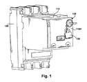
- a motor operator 110 is shown installed on a circuit breaker 100.
- a circuit breaker 100 a motor operator 110 is shown installed on a circuit breaker 100.
- the embodiments disclosed will be described with reference to the drawings, it should be understood that the embodiments disclosed can be embodied in many alternate forms. In addition, any suitable size, shape or type of elements or materials could be used. It should also be understood that while the exemplary embodiments are described herein with respect to motor operator 110, that the exemplary embodiments can be equally applied to any suitable circuit breaker accessory.
- the exemplary embodiments provide a user friendly lock assembly 120 for a circuit breaker accessory such as, for example, motor operator 110 that can be easily installed in the field.
- the lock assembly can be installed on the housing 110H of the motor operator 110 without removing or opening the housing 110H of the motor operator 110.
- the lock assembly 120 may be configured to engage any suitable portion of the motor operator mechanism for selectively disabling the motor operator and preventing unauthorized operation of the motor operator.
- the lock assembly 120 may be used in lieu of or in conjunction with other lockout devices such as a padlock 130.
- the lock assembly includes a keyed lock 200 and a lock mounting device in the form of a lock housing 230.
- the lock mounting device, or housing 230 is a cylindrical housing having a body 230B with a center aperture 230A.
- the lock housing 230 may be formed in any suitable manner of any suitable material including but not limited to, plastics, metals and composites.
- a first end 320 of the housing includes a collar 230C that extends radially outward away from the body 230B so as to form a shoulder 230S between the collar 230C and body 230B.
- the lock housing 230 includes at least one tab 300 extending radially outward from the collar 230C.
- the tab 300 may have any suitable configuration for interfacing with the motor operator housing 110H for substantially preventing rotation of the lock housing 230 when the lock assembly 120 is installed on the motor operator housing 110H as will be described below.
- relative movement between the lock mounting device, also referred to as the lock housing 230, and the motor operator housing 110H may be achieved in any suitable manner.
- the lock housing 230 may also include at least one resilient member 310 integrally formed in the body 230B adjacent the collar 230C.
- the resilient member 310 may be affixed to the lock housing 230 in any suitable manner.
- the lock housing 230 includes two resilient members 310 disposed substantially opposite one another on the lock housing 230.
- each of the resilient members 310 includes a lip 400 that extends radially outward from the body 230B.
- the lip 400 is spaced apart from the shoulder 230S by a suitable distance D so that the lip 400 and the shoulder 230S form respective channels 630.
- Each channel 630 is configured so that a portion of the motor operator housing 110H is accepted in the channel 630 for retaining the lock assembly 120 on the motor operator housing 110H as will be described below.
- the lock housing 230 may have any suitable configuration.
- the keyed lock 200 may be any suitable lock including but not limited to Ronis and Proflux key locks.
- the keyed lock 200 includes a lock body 210, key 200K and a cam 260.
- the lock body 210 may include at least one orientation surface such as, for exemplary purposes only, flat surfaces 210F formed in the lock body 210 for substantially preventing rotation of the lock body 210 within the lock housing 230.
- the flat surfaces 210F of the lock body 210 substantially contact corresponding orientation surfaces, such as flat surfaces 610, formed on an inner wall 620 of the aperture 230A of the lock housing 230.
- the lock body 210 may include at least one slot (not shown) formed in the lock body 210 that is configured to substantially engage a corresponding tab of the lock housing 500 (which may be substantially similar to lock housing 230), such as tab 510, that extends radially inward from the inner wall 620 of the aperture 230A for substantially preventing rotation of the lock body 210 within the lock housing 230 ( Fig. 5 ).
- a corresponding tab of the lock housing 500 which may be substantially similar to lock housing 230
- tab 510 that extends radially inward from the inner wall 620 of the aperture 230A for substantially preventing rotation of the lock body 210 within the lock housing 230 ( Fig. 5 ).
- relative movement between the lock body 210 and the lock housing 230 may be prevented in any suitable manner.
- the lock body 210 may include a lock body lip 210L1 that is configured to substantially engage a retaining feature in the form of a lip 230L disposed on the inner wall 620 of the aperture for preventing the lock body 210 from passing through the aperture.
- the flat surfaces 210F may form shoulders 210L2 that are configured to substantially abut shoulders 610S formed by the flat surfaces 610 on the inner wall 620 of the aperture 230A for preventing the lock body 210 from passing through the aperture 230A.
- the lock body 210 is inserted into the aperture 230A of the lock housing 230 so that the key 200K (e.g. the keyed end of the lock body) is adjacent to or facing the same direction as the first end 320 of the lock housing 230.
- the key 200K e.g. the keyed end of the lock body
- the lock body 210 is inserted into the lock housing 230 at least a portion of the lock body 210 and a shaft 220 of the lock extends from a second end 330 of the lock housing 230.
- At least the portion of the lock body that extends from the second end 330 of the lock housing 230 may be threaded for accepting a nut 240.
- the nut 240 abuts the second end 330 of the lock housing 230 and works in conjunction with the lip 210L1 and/or shoulder 210L2 for securing the lock body 210 to the lock housing 230.
- the lock body may include a slot configured to accept a clip where the clip abuts the second end 330 of the lock housing 230 for securing the lock body 210 in the lock housing 230.
- the lock body may include resilient members that engage or snap into suitable features of the lock housing for securing the lock body into the housing.
- any suitable fastening device may be used to secure the lock body 210 within the lock housing 230. Referring also to Fig.
- FIG. 7 an exemplary illustration of the lock body 210 being secured within the lock housing 230 is shown.
- a portion of the lock housing 230 e.g. the portion of the lock housing 230 forming the flat surface 610 is sandwiched between the shoulders 210L2 of the lock body 210 and the nut 240 for securing the lock body 210 within the lock housing 230.
- lock body 210 may be flush with or extend past the first end of the lock housing 230.
- the cam 260 may be configured to engage any suitable portion of the motor operator mechanism for disabling the motor operator 110 and preventing unauthorized use of the motor operator 110.
- the cam 260 may be fit over shaft 220 and secured to the shaft in any suitable manner.
- the cam 260 includes an aperture that conforms to a shape of the shaft 220 such that the cam 260 is non-rotatable relative to the shaft 220.
- the shaft 220 includes threads for accepting a nut 270 for securing the cam 260 to the shaft 220 where the nut 270 sandwiches the cam between the nut 270 and a shoulder formed in the shaft 220.
- Suitable washers or bushings 250 may be added between the cam 260 and the lock body 210 for any suitable purpose including, but not limited to, adjusting a distance between the cam 260 and, for example, the shoulder 230S of the lock housing 230.
- the washers 250 (in lieu of the shoulder formed in the shaft 220) may work in conjunction with the nut 270 for securing the cam 260 to the shaft 220.
- the cam 260 may be rotated relative to the lock body 210 (and the lock housing 230) for selectively disabling the motor operator 110 (when the lock assembly 120 is installed on the motor operator housing 110H) by inserting the key 200K into the lock body 210 and turning the key 200K.
- the motor operator housing 110H includes a recess 700 configured to accept the lock assembly 120.
- the recess 700 includes a lip 710 that extends radially inward so as to form an aperture 900.
- the aperture is blocked by a knockout 800 that is minimally attached to the lip 710 so that the knockout is easily removed from the aperture 900.
- the recess also includes a slot 810 configured to accept the tab 300 of the lock housing 230.
- the knockout 800 is removed from the aperture 900 in any suitable manner without opening or removing the motor operator housing 110H from the motor operator 110.
- the lock assembly 120 is inserted through the aperture 900 in the direction of arrow A.
- the tab 300 of the lock housing is aligned with the slot 810 in the motor operator housing 110H and the resilient members 310 are biased radially inward by the lip 710 of the recess 700.
- the resilient member lips 400 pass by the lip 710 of the recess 700 the resilient members 310 snap back into their unbiased position so that the lips 400 are located below and substantially contact a bottom surface 700B of the recess 700 as the shoulder 230S of the collar 230C substantially contacts the lip 710 as best seen in Fig. 7 .
- the resilient member lips 400 and the shoulder 230S capture the lip 710 of the recess 700 in the channel 630 for securing the lock assembly 120 on the motor operator housing 110H while the interaction between the tab 300 of the lock housing 230 and the slot 810 prevent rotation of the lock housing 230 and lock body 210 relative to the motor operator housing 110H.
- the cam 260 may then be rotated using the key 200K to selectively engage and disable the motor operator mechanism.
Landscapes
- Switch Cases, Indication, And Locking (AREA)
- Motor Or Generator Frames (AREA)
- Breakers (AREA)
Abstract
Description
- The subject matter described herein relates generally to circuit breaker accessories and, more particularly, to lock assemblies for circuit breaker accessories.
- It is known in the art to provide molded case circuit breakers for electrical systems. The circuit breaker is operative to disengage the electrical system under certain operating conditions. The use of accessories such as, for exemplary purposes only, motor operators to allow the motor-assisted operation of electrical circuit breakers is well known. The motor operator allows the circuit breaker to be operated remotely and to be opened, closed or reset after tripping of the circuit breaker.
- The motor operator is typically secured to the top of a circuit breaker housing. A lever within the motor operator mechanically interacts with a circuit breaker operating handle, which extends from the circuit breaker housing. The lever is operatively connected to a motor within the motor operator. The motor drives the lever, which, in turn, moves the operating handle to operate the circuit breaker. The operating handle is moved between "on", "off", and "reset" positions, depending on the rotational direction of the motor.
- A plurality of buttons external to the motor operator controls electrical current to the motor. The rotational direction of the motor is changed depending on which of these buttons is selected by operating personnel. Thus, the operating personnel can select one button to place the operating handle in the "on" position, and another button to place the operating handle in the "off" or "reset" positions.
- When the handle is moved to the "on" position, electrical contacts within the circuit breaker are brought into contact with each other, allowing electrical current to flow through the circuit breaker. When the handle is moved to the "off" position, the electrical contacts are separated, stopping the flow of electrical current through the circuit breaker. When the handle is moved to the "reset" position, an operating mechanism within the circuit breaker is reset, as is necessary after the operating mechanism has tripped in response to an overcurrent condition in the electrical circuit being protected by the circuit breaker.
- In one example, the circuit breaker accessory such as the motor operator described above may include one or more lockout devices such as padlocks or keyed cylinders for preventing unauthorized operation of the motor operator. In one example, the lockout devices may disable the motor operator mechanism in any suitable manner. Generally the padlocks are inserted through an aperture in a piece of, for example, the motor operator mechanism that protrudes through the motor operator housing or cover. The keyed cylinders are generally installed by opening the housing of, for example, the motor operator and assembling the keyed cylinder onto the housing.
- It would be advantageous to be able to install a keyed cylinder onto a circuit breaker accessory in the field without removing or opening the housing of the circuit breaker accessory.
- In accordance with one exemplary embodiment, a lock housing for a circuit breaker accessory housing includes a body having a aperture configured to receive a keyed lock, a collar circumscribing the aperture at a first end of the housing, the collar extending radially outward from the body, and at least one resilient member integral to the housing, the at least one resilient member configured to engage the circuit breaker accessory housing.
- In accordance with another exemplary embodiment, a lock assembly for a circuit breaker accessory housing is disclosed, the housing comprising a retaining feature, wherein the lock assembly includes a keyed lock and a lock housing having an aperture configured to retain the keyed lock, a collar circumscribing the aperture; and at least one resilient member adjacent the aperture, wherein the collar and the at least one resilient member cooperate to capture the retaining feature.
- In accordance with another exemplary embodiment, a circuit breaker accessory includes a circuit breaker accessory housing having an aperture and a lip surrounding the aperture, and a lock assembly secured to the circuit breaker accessory housing, the lock assembly configured to selectively disable the circuit breaker accessory, wherein the lock assembly includes a keyed lock, and a lock housing having an aperture configured to retain the keyed lock, a collar circumscribing the aperture, and at least one resilient member adjacent the aperture, wherein the collar and the at least one resilient member cooperate to capture the lip of the circuit breaker accessory housing.
- In accordance with still another exemplary embodiment, a method of installing a lock assembly on a circuit breaker accessory housing includes inserting the lock assembly through an aperture in a surface of the circuit breaker accessory housing without opening the circuit breaker accessory housing, and capturing a lip of the aperture within a channel of the lock assembly such that the lip is substantially contacted on a first side by a resilient member of the lock assembly and on a second opposite side by a collar of the lock assembly..
- The following detailed description is made with reference to the accompanying drawings, in which:
-
Fig. 1 is a schematic illustration of a circuit breaker accessory coupled to a circuit breaker in accordance with an exemplary embodiment; -
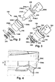
Fig. 2 is an exploded illustration of a lock assembly in accordance with an exemplary embodiment; -
Fig. 3 is a schematic illustration of the lock assembly ofFig. 2 in accordance with an exemplary embodiment; -
Fig. 4 is a schematic illustration of a portion of the lock assembly ofFig. 2 in accordance with an exemplary embodiment; -
Fig. 5 is a schematic illustration of a portion of the lock assembly ofFig. 2 in accordance with an exemplary embodiment; -
Fig. 6 is a schematic illustration of a portion of the lock assembly ofFig. 2 in accordance with an exemplary embodiment; -
Fig. 7 is a schematic sectional illustration of the lock assembly ofFig. 2 and a portion of the circuit breaker accessory ofFig. 1 in accordance with an exemplary embodiment; and -
Figs. 8 through 11 illustrate an exemplary installation of a key assembly in accordance with an exemplary embodiment. - In one exemplary embodiment, referring to
Fig. 1 amotor operator 110 is shown installed on acircuit breaker 100. Although the embodiments disclosed will be described with reference to the drawings, it should be understood that the embodiments disclosed can be embodied in many alternate forms. In addition, any suitable size, shape or type of elements or materials could be used. It should also be understood that while the exemplary embodiments are described herein with respect tomotor operator 110, that the exemplary embodiments can be equally applied to any suitable circuit breaker accessory. - The exemplary embodiments provide a user
friendly lock assembly 120 for a circuit breaker accessory such as, for example,motor operator 110 that can be easily installed in the field. In accordance with an exemplary embodiment the lock assembly can be installed on thehousing 110H of themotor operator 110 without removing or opening thehousing 110H of themotor operator 110. Thelock assembly 120 may be configured to engage any suitable portion of the motor operator mechanism for selectively disabling the motor operator and preventing unauthorized operation of the motor operator. Thelock assembly 120 may be used in lieu of or in conjunction with other lockout devices such as apadlock 130. - Referring to
Figs. 2-6 the lock assembly includes a keyedlock 200 and a lock mounting device in the form of alock housing 230. The lock mounting device, orhousing 230 is a cylindrical housing having abody 230B with acenter aperture 230A. Thelock housing 230 may be formed in any suitable manner of any suitable material including but not limited to, plastics, metals and composites. Afirst end 320 of the housing includes acollar 230C that extends radially outward away from thebody 230B so as to form ashoulder 230S between thecollar 230C andbody 230B. Thelock housing 230 includes at least onetab 300 extending radially outward from thecollar 230C. Thetab 300 may have any suitable configuration for interfacing with themotor operator housing 110H for substantially preventing rotation of thelock housing 230 when thelock assembly 120 is installed on themotor operator housing 110H as will be described below. In other examples, relative movement between the lock mounting device, also referred to as thelock housing 230, and themotor operator housing 110H may be achieved in any suitable manner. Thelock housing 230 may also include at least oneresilient member 310 integrally formed in thebody 230B adjacent thecollar 230C. In other examples theresilient member 310 may be affixed to thelock housing 230 in any suitable manner. In this example, thelock housing 230 includes tworesilient members 310 disposed substantially opposite one another on thelock housing 230. In other examples there may be more than tworesilient members 310 having any suitable positional relationship with each other. Each of theresilient members 310 includes alip 400 that extends radially outward from thebody 230B. Thelip 400 is spaced apart from theshoulder 230S by a suitable distance D so that thelip 400 and theshoulder 230S formrespective channels 630. Eachchannel 630 is configured so that a portion of themotor operator housing 110H is accepted in thechannel 630 for retaining thelock assembly 120 on themotor operator housing 110H as will be described below. In other examples thelock housing 230 may have any suitable configuration. - The keyed
lock 200 may be any suitable lock including but not limited to Ronis and Proflux key locks. In one example, thekeyed lock 200 includes alock body 210, key 200K and acam 260. Thelock body 210 may include at least one orientation surface such as, for exemplary purposes only,flat surfaces 210F formed in thelock body 210 for substantially preventing rotation of thelock body 210 within thelock housing 230. In this example, theflat surfaces 210F of thelock body 210 substantially contact corresponding orientation surfaces, such asflat surfaces 610, formed on aninner wall 620 of theaperture 230A of thelock housing 230. In other examples thelock body 210 may include at least one slot (not shown) formed in thelock body 210 that is configured to substantially engage a corresponding tab of the lock housing 500 (which may be substantially similar to lock housing 230), such astab 510, that extends radially inward from theinner wall 620 of theaperture 230A for substantially preventing rotation of thelock body 210 within the lock housing 230 (Fig. 5 ). In still other examples, relative movement between thelock body 210 and thelock housing 230 may be prevented in any suitable manner. In one example, thelock body 210 may include a lock body lip 210L1 that is configured to substantially engage a retaining feature in the form of alip 230L disposed on theinner wall 620 of the aperture for preventing thelock body 210 from passing through the aperture. In another example, theflat surfaces 210F may form shoulders 210L2 that are configured to substantially abutshoulders 610S formed by theflat surfaces 610 on theinner wall 620 of theaperture 230A for preventing thelock body 210 from passing through theaperture 230A. - In accordance with an exemplary embodiment, the
lock body 210 is inserted into theaperture 230A of thelock housing 230 so that the key 200K (e.g. the keyed end of the lock body) is adjacent to or facing the same direction as thefirst end 320 of thelock housing 230. Whenlock body 210 is inserted into thelock housing 230 at least a portion of thelock body 210 and ashaft 220 of the lock extends from asecond end 330 of thelock housing 230. At least the portion of the lock body that extends from thesecond end 330 of thelock housing 230 may be threaded for accepting anut 240. Thenut 240 abuts thesecond end 330 of thelock housing 230 and works in conjunction with the lip 210L1 and/or shoulder 210L2 for securing thelock body 210 to thelock housing 230. In one example, the lock body may include a slot configured to accept a clip where the clip abuts thesecond end 330 of thelock housing 230 for securing thelock body 210 in thelock housing 230. In another example, the lock body may include resilient members that engage or snap into suitable features of the lock housing for securing the lock body into the housing. In still other examples, any suitable fastening device may be used to secure thelock body 210 within thelock housing 230. Referring also toFig. 7 , an exemplary illustration of thelock body 210 being secured within thelock housing 230 is shown. In this example, a portion of the lock housing 230 (e.g. the portion of thelock housing 230 forming the flat surface 610) is sandwiched between the shoulders 210L2 of thelock body 210 and thenut 240 for securing thelock body 210 within thelock housing 230. - It is noted that while the exemplary embodiments describe the lock body as being recessed relative to the
first end 320 of thelock housing 230, in other examples thelock body 210 may be flush with or extend past the first end of thelock housing 230. - The
cam 260 may be configured to engage any suitable portion of the motor operator mechanism for disabling themotor operator 110 and preventing unauthorized use of themotor operator 110. Thecam 260 may be fit overshaft 220 and secured to the shaft in any suitable manner. In one example, thecam 260 includes an aperture that conforms to a shape of theshaft 220 such that thecam 260 is non-rotatable relative to theshaft 220. In one example, theshaft 220 includes threads for accepting anut 270 for securing thecam 260 to theshaft 220 where thenut 270 sandwiches the cam between thenut 270 and a shoulder formed in theshaft 220. Suitable washers orbushings 250 may be added between thecam 260 and thelock body 210 for any suitable purpose including, but not limited to, adjusting a distance between thecam 260 and, for example, theshoulder 230S of thelock housing 230. The washers 250 (in lieu of the shoulder formed in the shaft 220) may work in conjunction with thenut 270 for securing thecam 260 to theshaft 220. Thecam 260 may be rotated relative to the lock body 210 (and the lock housing 230) for selectively disabling the motor operator 110 (when thelock assembly 120 is installed on themotor operator housing 110H) by inserting the key 200K into thelock body 210 and turning the key 200K. - Referring now to
Figs. 7-11 an exemplary installation of thelock assembly 120 will be described. In this example, themotor operator housing 110H includes arecess 700 configured to accept thelock assembly 120. Therecess 700 includes alip 710 that extends radially inward so as to form anaperture 900. The aperture is blocked by aknockout 800 that is minimally attached to thelip 710 so that the knockout is easily removed from theaperture 900. The recess also includes aslot 810 configured to accept thetab 300 of thelock housing 230. During installation of thelock assembly 120, theknockout 800 is removed from theaperture 900 in any suitable manner without opening or removing themotor operator housing 110H from themotor operator 110. Thelock assembly 120 is inserted through theaperture 900 in the direction of arrow A. As thelock housing 230 is inserted through theaperture 900 thetab 300 of the lock housing is aligned with theslot 810 in themotor operator housing 110H and theresilient members 310 are biased radially inward by thelip 710 of therecess 700. As theresilient member lips 400 pass by thelip 710 of therecess 700 theresilient members 310 snap back into their unbiased position so that thelips 400 are located below and substantially contact abottom surface 700B of therecess 700 as theshoulder 230S of thecollar 230C substantially contacts thelip 710 as best seen inFig. 7 . Theresilient member lips 400 and theshoulder 230S capture thelip 710 of therecess 700 in thechannel 630 for securing thelock assembly 120 on themotor operator housing 110H while the interaction between thetab 300 of thelock housing 230 and theslot 810 prevent rotation of thelock housing 230 and lockbody 210 relative to themotor operator housing 110H. Thecam 260 may then be rotated using the key 200K to selectively engage and disable the motor operator mechanism. - While exemplary embodiments have been described in connection with what are presently considered to be the most practical and preferred embodiments, it is to be understood that the embodiments are not limited to those disclosed herein. Rather, the embodiments described are intended to cover all of the various modifications and equivalent arrangements included within the spirit and scope of the appended claims.
- Various aspects of the present invention are defined in the following numbered clauses:
- 1. A lock housing for a lock for a circuit breaker accessory housing, the lock housing comprising:
- a body having an aperture configured to receive the lock;
- a collar about the aperture at a first end of the lock housing, the collar extending radially outward from the lock housing; and
- at least one resilient member integral to the lock housing, the at least one resilient member configured to engage the circuit breaker accessory housing.
- 2. The lock housing of clause 1, further comprising at least one orientation surface disposed within the aperture configured to substantially prevent relative movement between the lock housing and the lock.
- 3. The lock housing of clause 2, further comprising a second end, wherein the orientation surface is adjacent to the second end the orientation surface, further comprising at least one surface formed on a wall of the aperture.
- 4. The lock housing of clause 2 or clause 3, wherein the orientation surface is a tab extending radially inward from the wall of the aperture.
- 5. The lock housing of any one of the preceding clauses, further comprising a shelf disposed within the aperture to at least partially retain the lock.
- 6. The lock housing of any one of the preceding clauses, further comprising a tab extending radially outward from the collar, the tab configured to engage the circuit breaker accessory housing and substantially prevent rotation of the housing.
- 7. A lock assembly for an accessory housing, the housing comprising a retention feature, wherein the lock assembly comprises:
- a lock;
- a lock housing comprising:
- an aperture configured to retain the lock;
- a collar about the aperture; and
- at least one resilient member adjacent the aperture,
- 8. The lock assembly of clause 7, wherein:
- the lock includes a body comprising a first orientation surface; and
- the aperture comprising an inner wall having a second orientation surface, wherein the first orientation surface and second orientation surface substantially prevent rotation of the body within the aperture.
- 9. The lock assembly of clause 7 or clause 8, wherein the lock housing includes a tab extending radially outward from the collar, the tab configured to engage a recess in the accessory housing.
- 10. The lock assembly of any one of clauses 7 to 9, wherein:
- the collar comprises a shoulder configured to contact a first side of the retention feature; and
- the at least one resilient member being configured to contact a second side of the retaining feature.
- 11. The lock assembly of any one of clauses 7 to 10, wherein:
- the lock housing comprises a first and second end, the collar being disposed at the first end;
- the lock comprises a body having a first shoulder;
- the aperture comprises an inner wall having a second shoulder configured to interface with the first shoulder; and
- a fastener coupled to the body for securing the body within the aperture.
- 12. The lock assembly of any one of clauses 7 to 11, wherein the lock includes a cam configured to selectively disable a mechanism housed within the circuit breaker accessory housing.
- 13. A circuit breaker accessory comprising:
- a circuit breaker accessory housing having an aperture;
- a lip proximate the aperture;
- a lock assembly secured to the circuit breaker accessory housing, the lock assembly configured to selectively disable the circuit breaker accessory, wherein the lock assembly includes,
- a lock; and
- a lock housing having:
- an aperture configured to retain the lock;
- a collar about the aperture; and
- at least one resilient member adjacent the aperture,
- 14. The circuit breaker accessory of clause 13, wherein:
- the lock comprises a body, the body including a first orientation surface; and
- the lock housing aperture includes an inner wall having a second orientation surface, wherein the first orientation surface and second orientation surface cooperate to substantially prevent rotation of the body within the lock housing aperture.
- 15. The circuit breaker accessory of clause 13 or clause 14, wherein the lock housing includes a tab configured to extend radially outward from the collar, the recess being configured to engage the tab to prevent rotation of the lock housing.
- 16. The circuit breaker accessory of any one of clauses 13 to 15, wherein the at least one resilient member is integrally formed with the lock housing.
- 17. The circuit breaker accessory of any one of clauses 13 to 16, wherein:
- the collar comprises a shoulder configured to contact a first side of the lip of the circuit breaker accessory housing; and
- the at least one resilient member comprising a resilient member lip configured to contact the lip of the circuit breaker accessory housing, the shoulder and resilient member lip being oriented to capture the lip of the circuit breaker accessory housing.
- 18. The circuit breaker accessory of any one of clauses 13 to 17, wherein:
- the lock housing comprises a first and second end, the collar being disposed at the first end;
- the keyed lock comprises a body having a first shoulder;
- the aperture comprises an inner wall having a second shoulder configured to interface with the first shoulder; and
- a fastener abutting the second end is coupled to the body to secure the body within the aperture.
- 19. The circuit breaker accessory of any one of clauses 13 to 18, wherein the lock includes a cam configured to selectively disable a mechanism housed within the circuit breaker accessory housing.
- 20. The circuit breaker accessory of any one of clauses 13 to 19, wherein the lock assembly is securable within the recess with the circuit breaker accessory housing closed.
- 21. A method of installing a lock assembly on a circuit breaker accessory housing, the method comprising:
- inserting the lock assembly through an aperture in a surface of the circuit breaker accessory housing without opening the circuit breaker accessory housing; and
- capturing a lip of the aperture within a channel of the lock assembly such that the lip is substantially contacted on a first side by a resilient member of the lock assembly and on a second side by a collar of the lock assembly.
- 22. The method of clause 21, further comprising inserting a keyed lock within a lock housing for forming the lock assembly, where a body of the keyed lock is non-rotatably secured to the lock housing.
Claims (10)
- A lock housing (230) for a lock (200) for a circuit breaker accessory housing (110H), the lock housing (230) comprising:a body (230B) having an aperture (230A) configured to receive the lock (200);a collar (230C) about the aperture (230A) at a first end of the lock housing (230), the collar (230C) extending radially outward from the lock housing (230); andat least one resilient member (310) integral to the lock housing (230), the at least one resilient member (310) configured to engage the circuit breaker accessory housing (110H).
- The lock housing (230) of claim 1, further comprising at least one orientation surface disposed within the aperture (230A) configured to substantially prevent relative movement between the lock housing (230) and the lock (200).
- The lock housing (230) of claim 1 or claim 2, further comprising a tab (300) extending radially outward from the collar (230C), the tab (300) configured to engage the circuit breaker accessory housing (110H) and substantially prevent rotation of the housing (230).
- A lock assembly (120) for an accessory housing (110H), the housing (110H) comprising a retention feature, wherein the lock assembly (120) comprises:a lock (200);a lock housing (230) comprising:wherein the collar (230C) and the at least one resilient member (310) cooperate to capture the retention feature.an aperture (230A) configured to retain the lock (200);a collar (230C) about the aperture (230A); andat least one resilient member (310) adjacent the aperture (230A),
- The lock assembly (120) of claim 4, wherein:the lock (200) includes a body (230B) comprising a first orientation surface; andthe aperture (230A) comprising an inner wall having a second orientation surface, wherein the first orientation surface and second orientation surface substantially prevent rotation of the body (230B) within the aperture (230A).
- The lock assembly (120) of claim 4 or claim 5, wherein the lock housing (230) includes a tab (300) extending radially outward from the collar (230C), the tab (300) configured to engage a recess in the accessory housing (110H).
- The lock assembly (120) of any one of claims 4 to 6, wherein the lock (200) includes a cam (260) configured to selectively disable a mechanism housed within the circuit breaker accessory housing (110H).
- A circuit breaker accessory comprising:a circuit breaker accessory housing (110H) having an aperture (230A);a lip proximate the aperture (230A);a lock assembly (120) secured to the circuit breaker accessory housing (110H), the lock assembly (120) configured to selectively disable the circuit breaker accessory, wherein the lock assembly (120) includes,a lock (200); anda lock housing (230) having:wherein the collar (230C) and the at least one resilient member (310) cooperate to capture the lip of the circuit breaker accessory housing (110H).an aperture (230A) configured to retain the lock (200);a collar (230C) about the aperture (230A); andat least one resilient member (310) adjacent the aperture (230A),
- The circuit breaker accessory of claim 8, wherein the at least one resilient member (310) is integrally formed with the lock housing (230).
- The circuit breaker accessory of claim 8 or claim 9, wherein the lock (200) includes a cam (260) configured to selectively disable a mechanism housed within the circuit breaker accessory housing (110H).
Priority Applications (1)
| Application Number | Priority Date | Filing Date | Title |
|---|---|---|---|
| PL10161344T PL2249362T3 (en) | 2009-05-01 | 2010-04-28 | Lock mounting device |
Applications Claiming Priority (1)
| Application Number | Priority Date | Filing Date | Title |
|---|---|---|---|
| US12/434,252 US8183479B2 (en) | 2009-05-01 | 2009-05-01 | Lock mounting device |
Publications (3)
| Publication Number | Publication Date |
|---|---|
| EP2249362A2 true EP2249362A2 (en) | 2010-11-10 |
| EP2249362A3 EP2249362A3 (en) | 2010-12-08 |
| EP2249362B1 EP2249362B1 (en) | 2012-08-22 |
Family
ID=42370886
Family Applications (1)
| Application Number | Title | Priority Date | Filing Date |
|---|---|---|---|
| EP10161344A Active EP2249362B1 (en) | 2009-05-01 | 2010-04-28 | Lock mounting device |
Country Status (4)
| Country | Link |
|---|---|
| US (1) | US8183479B2 (en) |
| EP (1) | EP2249362B1 (en) |
| CN (1) | CN101876225B (en) |
| PL (1) | PL2249362T3 (en) |
Families Citing this family (6)
| Publication number | Priority date | Publication date | Assignee | Title |
|---|---|---|---|---|
| US8598477B2 (en) | 2009-10-13 | 2013-12-03 | Barton L. Garvin | Universal switch restraint device |
| US8937259B2 (en) | 2009-10-13 | 2015-01-20 | Barton L. Garvin | Universal electrical circuit breaker locking device |
| KR101060786B1 (en) * | 2009-11-19 | 2011-08-30 | 엘에스산전 주식회사 | Lock of circuit breaker |
| CN102832061B (en) * | 2012-08-23 | 2014-11-19 | 德力西电气有限公司 | Space-saving brake separating lock |
| CN103871762B (en) * | 2012-12-13 | 2016-04-13 | 西门子公司 | breaker |
| US9812268B2 (en) * | 2016-02-11 | 2017-11-07 | Siemens Aktiengesellschaft | Systems and methods for locking a circuit breaker |
Family Cites Families (14)
| Publication number | Priority date | Publication date | Assignee | Title |
|---|---|---|---|---|
| US1774628A (en) * | 1925-06-17 | 1930-09-02 | Albert & J M Anderson Mfg Co | Manhole switch |
| US4554421A (en) * | 1984-01-09 | 1985-11-19 | Westinghouse Electric Corp. | Molded case circuit breaker with handle lock |
| US4803314A (en) * | 1986-12-22 | 1989-02-07 | Carlingswitch, Inc. | Momentary rotary switch |
| US5146056A (en) * | 1991-04-29 | 1992-09-08 | Kuczynski Robert A | Snap-in bracket for circuit breaker |
| US5166651A (en) * | 1991-07-26 | 1992-11-24 | General Electric Company | Molded case circuit breaker arc exhaust gas controller |
| US5693923A (en) * | 1996-04-15 | 1997-12-02 | Eaton Corporation | Motor operator for electrical switches |
| US5905239A (en) * | 1996-08-19 | 1999-05-18 | Eaton Corporation | Motor operator with burn-out protection |
| US5769208A (en) * | 1996-11-29 | 1998-06-23 | Griffith; Charles E. | Lockable assembly for engaging and disengaging a motor operator with an overhead distribution gang switch |
| US6446475B1 (en) * | 2000-06-12 | 2002-09-10 | Itt Manufacturing Enterprises, Inc. | Switchlock assembly with snap-in cam |
| US6791040B1 (en) * | 2003-09-15 | 2004-09-14 | Eaton Corporation | Locking assembly for an electrical switching apparatus |
| DE102005005393A1 (en) * | 2005-02-02 | 2006-08-10 | IKON GmbH Präzisionstechnik | Cylinder lock, has electrical switch arranged with or at cylindrical housing and exhibiting pin, which is pressable by key directly or indirectly in ON-position to detect presence of key |
| US7271355B2 (en) * | 2005-11-01 | 2007-09-18 | Honeywell International Inc. | Locking mechanism for a safety switch |
| WO2008055254A2 (en) | 2006-11-01 | 2008-05-08 | Board Of Regents, The University Of Texas System | Formulations and methods for oral delivery of proteins |
| US20080277249A1 (en) * | 2007-05-10 | 2008-11-13 | Antonio Zubieta | Circuit breaker with improved lock-off accessory |
-
2009
- 2009-05-01 US US12/434,252 patent/US8183479B2/en not_active Expired - Fee Related
-
2010
- 2010-04-28 EP EP10161344A patent/EP2249362B1/en active Active
- 2010-04-28 PL PL10161344T patent/PL2249362T3/en unknown
- 2010-04-29 CN CN201010175157.XA patent/CN101876225B/en active Active
Non-Patent Citations (1)
| Title |
|---|
| None |
Also Published As
| Publication number | Publication date |
|---|---|
| PL2249362T3 (en) | 2013-01-31 |
| CN101876225A (en) | 2010-11-03 |
| EP2249362B1 (en) | 2012-08-22 |
| US20100276261A1 (en) | 2010-11-04 |
| US8183479B2 (en) | 2012-05-22 |
| CN101876225B (en) | 2014-01-29 |
| EP2249362A3 (en) | 2010-12-08 |
Similar Documents
| Publication | Publication Date | Title |
|---|---|---|
| EP2249362B1 (en) | Lock mounting device | |
| US6194983B1 (en) | Molded case circuit breaker with current flow indicating handle mechanism | |
| US6423912B1 (en) | Manually operated device having a turning handle for electrical switching devices | |
| CA1272501A (en) | Door mounted circuit breaker operating apparatus | |
| US6797903B1 (en) | Extended rotary handle operator | |
| EP1531484B1 (en) | Fuse block with integral door sensing rotary disconnect | |
| US8664552B2 (en) | Lockable turning handle | |
| CA2509477C (en) | Fuse block with integral door sensing rotary disconnect | |
| US8859917B2 (en) | Electrical switch latch assembly | |
| EP1194938A2 (en) | Locking device for molded case circuit breakers | |
| EP2472547B1 (en) | Locking device for use with a circuit breaker and method of assembly | |
| US20080277249A1 (en) | Circuit breaker with improved lock-off accessory | |
| CN103201807A (en) | Rotary interlock mechanism for electrical switches | |
| US20060278504A1 (en) | Mountable lockout device | |
| US6949711B1 (en) | Selector switch knob with lock ring assembly | |
| US9053876B2 (en) | Lockable manually-operated actuator for electrical switching devices | |
| US9177732B2 (en) | Flexible cable assembly with improved manufacturability | |
| EP2874173B1 (en) | Flexible cable assembly providing local lockout | |
| EP4250324B1 (en) | Rotary lockout tagout latch system | |
| EP0992048B1 (en) | Circuit breaker movable actuator blocking and securing means | |
| GB2149972A (en) | Hand-operated device for an electric switch | |
| EP2472540B1 (en) | Switching assembly having an interlock device for a selector switch | |
| CN103282987A (en) | Locking device and switch with locking device | |
| CN209747371U (en) | Circuit breaker safety lock | |
| EP2242079B1 (en) | Device for mounting an accessory device to a circuit breaker |
Legal Events
| Date | Code | Title | Description |
|---|---|---|---|
| PUAI | Public reference made under article 153(3) epc to a published international application that has entered the european phase |
Free format text: ORIGINAL CODE: 0009012 |
|
| PUAL | Search report despatched |
Free format text: ORIGINAL CODE: 0009013 |
|
| AK | Designated contracting states |
Kind code of ref document: A2 Designated state(s): AT BE BG CH CY CZ DE DK EE ES FI FR GB GR HR HU IE IS IT LI LT LU LV MC MK MT NL NO PL PT RO SE SI SK SM TR |
|
| AX | Request for extension of the european patent |
Extension state: AL BA ME RS |
|
| AK | Designated contracting states |
Kind code of ref document: A3 Designated state(s): AT BE BG CH CY CZ DE DK EE ES FI FR GB GR HR HU IE IS IT LI LT LU LV MC MK MT NL NO PL PT RO SE SI SK SM TR |
|
| AX | Request for extension of the european patent |
Extension state: AL BA ME RS |
|
| RIC1 | Information provided on ipc code assigned before grant |
Ipc: H01H 9/24 20060101AFI20101001BHEP Ipc: H01H 27/06 20060101ALI20101029BHEP |
|
| 17P | Request for examination filed |
Effective date: 20110608 |
|
| GRAP | Despatch of communication of intention to grant a patent |
Free format text: ORIGINAL CODE: EPIDOSNIGR1 |
|
| RIN1 | Information on inventor provided before grant (corrected) |
Inventor name: POMMERENCKE, LARS Inventor name: MITTU, MAHADEVA Inventor name: RAJAURIA, SAMIR |
|
| GRAS | Grant fee paid |
Free format text: ORIGINAL CODE: EPIDOSNIGR3 |
|
| GRAA | (expected) grant |
Free format text: ORIGINAL CODE: 0009210 |
|
| AK | Designated contracting states |
Kind code of ref document: B1 Designated state(s): AT BE BG CH CY CZ DE DK EE ES FI FR GB GR HR HU IE IS IT LI LT LU LV MC MK MT NL NO PL PT RO SE SI SK SM TR |
|
| REG | Reference to a national code |
Ref country code: GB Ref legal event code: FG4D |
|
| REG | Reference to a national code |
Ref country code: CH Ref legal event code: EP |
|
| REG | Reference to a national code |
Ref country code: IE Ref legal event code: FG4D |
|
| REG | Reference to a national code |
Ref country code: AT Ref legal event code: REF Ref document number: 572337 Country of ref document: AT Kind code of ref document: T Effective date: 20120915 |
|
| REG | Reference to a national code |
Ref country code: DE Ref legal event code: R096 Ref document number: 602010002387 Country of ref document: DE Effective date: 20121018 |
|
| REG | Reference to a national code |
Ref country code: NL Ref legal event code: VDEP Effective date: 20120822 |
|
| REG | Reference to a national code |
Ref country code: AT Ref legal event code: MK05 Ref document number: 572337 Country of ref document: AT Kind code of ref document: T Effective date: 20120822 |
|
| REG | Reference to a national code |
Ref country code: LT Ref legal event code: MG4D Effective date: 20120822 |
|
| PG25 | Lapsed in a contracting state [announced via postgrant information from national office to epo] |
Ref country code: AT Free format text: LAPSE BECAUSE OF FAILURE TO SUBMIT A TRANSLATION OF THE DESCRIPTION OR TO PAY THE FEE WITHIN THE PRESCRIBED TIME-LIMIT Effective date: 20120822 Ref country code: FI Free format text: LAPSE BECAUSE OF FAILURE TO SUBMIT A TRANSLATION OF THE DESCRIPTION OR TO PAY THE FEE WITHIN THE PRESCRIBED TIME-LIMIT Effective date: 20120822 Ref country code: LT Free format text: LAPSE BECAUSE OF FAILURE TO SUBMIT A TRANSLATION OF THE DESCRIPTION OR TO PAY THE FEE WITHIN THE PRESCRIBED TIME-LIMIT Effective date: 20120822 Ref country code: NO Free format text: LAPSE BECAUSE OF FAILURE TO SUBMIT A TRANSLATION OF THE DESCRIPTION OR TO PAY THE FEE WITHIN THE PRESCRIBED TIME-LIMIT Effective date: 20121122 Ref country code: HR Free format text: LAPSE BECAUSE OF FAILURE TO SUBMIT A TRANSLATION OF THE DESCRIPTION OR TO PAY THE FEE WITHIN THE PRESCRIBED TIME-LIMIT Effective date: 20120822 Ref country code: IS Free format text: LAPSE BECAUSE OF FAILURE TO SUBMIT A TRANSLATION OF THE DESCRIPTION OR TO PAY THE FEE WITHIN THE PRESCRIBED TIME-LIMIT Effective date: 20121222 |
|
| REG | Reference to a national code |
Ref country code: PL Ref legal event code: T3 |
|
| PG25 | Lapsed in a contracting state [announced via postgrant information from national office to epo] |
Ref country code: BE Free format text: LAPSE BECAUSE OF FAILURE TO SUBMIT A TRANSLATION OF THE DESCRIPTION OR TO PAY THE FEE WITHIN THE PRESCRIBED TIME-LIMIT Effective date: 20120822 Ref country code: PT Free format text: LAPSE BECAUSE OF FAILURE TO SUBMIT A TRANSLATION OF THE DESCRIPTION OR TO PAY THE FEE WITHIN THE PRESCRIBED TIME-LIMIT Effective date: 20121224 Ref country code: GR Free format text: LAPSE BECAUSE OF FAILURE TO SUBMIT A TRANSLATION OF THE DESCRIPTION OR TO PAY THE FEE WITHIN THE PRESCRIBED TIME-LIMIT Effective date: 20121123 Ref country code: SI Free format text: LAPSE BECAUSE OF FAILURE TO SUBMIT A TRANSLATION OF THE DESCRIPTION OR TO PAY THE FEE WITHIN THE PRESCRIBED TIME-LIMIT Effective date: 20120822 Ref country code: SE Free format text: LAPSE BECAUSE OF FAILURE TO SUBMIT A TRANSLATION OF THE DESCRIPTION OR TO PAY THE FEE WITHIN THE PRESCRIBED TIME-LIMIT Effective date: 20120822 Ref country code: LV Free format text: LAPSE BECAUSE OF FAILURE TO SUBMIT A TRANSLATION OF THE DESCRIPTION OR TO PAY THE FEE WITHIN THE PRESCRIBED TIME-LIMIT Effective date: 20120822 |
|
| PG25 | Lapsed in a contracting state [announced via postgrant information from national office to epo] |
Ref country code: NL Free format text: LAPSE BECAUSE OF FAILURE TO SUBMIT A TRANSLATION OF THE DESCRIPTION OR TO PAY THE FEE WITHIN THE PRESCRIBED TIME-LIMIT Effective date: 20120822 |
|
| PG25 | Lapsed in a contracting state [announced via postgrant information from national office to epo] |
Ref country code: EE Free format text: LAPSE BECAUSE OF FAILURE TO SUBMIT A TRANSLATION OF THE DESCRIPTION OR TO PAY THE FEE WITHIN THE PRESCRIBED TIME-LIMIT Effective date: 20120822 Ref country code: CZ Free format text: LAPSE BECAUSE OF FAILURE TO SUBMIT A TRANSLATION OF THE DESCRIPTION OR TO PAY THE FEE WITHIN THE PRESCRIBED TIME-LIMIT Effective date: 20120822 Ref country code: ES Free format text: LAPSE BECAUSE OF FAILURE TO SUBMIT A TRANSLATION OF THE DESCRIPTION OR TO PAY THE FEE WITHIN THE PRESCRIBED TIME-LIMIT Effective date: 20121203 Ref country code: DK Free format text: LAPSE BECAUSE OF FAILURE TO SUBMIT A TRANSLATION OF THE DESCRIPTION OR TO PAY THE FEE WITHIN THE PRESCRIBED TIME-LIMIT Effective date: 20120822 Ref country code: RO Free format text: LAPSE BECAUSE OF FAILURE TO SUBMIT A TRANSLATION OF THE DESCRIPTION OR TO PAY THE FEE WITHIN THE PRESCRIBED TIME-LIMIT Effective date: 20120822 |
|
| PG25 | Lapsed in a contracting state [announced via postgrant information from national office to epo] |
Ref country code: SK Free format text: LAPSE BECAUSE OF FAILURE TO SUBMIT A TRANSLATION OF THE DESCRIPTION OR TO PAY THE FEE WITHIN THE PRESCRIBED TIME-LIMIT Effective date: 20120822 |
|
| PLBE | No opposition filed within time limit |
Free format text: ORIGINAL CODE: 0009261 |
|
| STAA | Information on the status of an ep patent application or granted ep patent |
Free format text: STATUS: NO OPPOSITION FILED WITHIN TIME LIMIT |
|
| 26N | No opposition filed |
Effective date: 20130523 |
|
| PG25 | Lapsed in a contracting state [announced via postgrant information from national office to epo] |
Ref country code: BG Free format text: LAPSE BECAUSE OF FAILURE TO SUBMIT A TRANSLATION OF THE DESCRIPTION OR TO PAY THE FEE WITHIN THE PRESCRIBED TIME-LIMIT Effective date: 20121122 |
|
| REG | Reference to a national code |
Ref country code: DE Ref legal event code: R097 Ref document number: 602010002387 Country of ref document: DE Effective date: 20130523 |
|
| PG25 | Lapsed in a contracting state [announced via postgrant information from national office to epo] |
Ref country code: CY Free format text: LAPSE BECAUSE OF FAILURE TO SUBMIT A TRANSLATION OF THE DESCRIPTION OR TO PAY THE FEE WITHIN THE PRESCRIBED TIME-LIMIT Effective date: 20120822 Ref country code: MC Free format text: LAPSE BECAUSE OF FAILURE TO SUBMIT A TRANSLATION OF THE DESCRIPTION OR TO PAY THE FEE WITHIN THE PRESCRIBED TIME-LIMIT Effective date: 20120822 |
|
| REG | Reference to a national code |
Ref country code: IE Ref legal event code: MM4A |
|
| PG25 | Lapsed in a contracting state [announced via postgrant information from national office to epo] |
Ref country code: IE Free format text: LAPSE BECAUSE OF NON-PAYMENT OF DUE FEES Effective date: 20130428 |
|
| PGFP | Annual fee paid to national office [announced via postgrant information from national office to epo] |
Ref country code: FR Payment date: 20140417 Year of fee payment: 5 Ref country code: IT Payment date: 20140424 Year of fee payment: 5 |
|
| REG | Reference to a national code |
Ref country code: CH Ref legal event code: PL |
|
| GBPC | Gb: european patent ceased through non-payment of renewal fee |
Effective date: 20140428 |
|
| PG25 | Lapsed in a contracting state [announced via postgrant information from national office to epo] |
Ref country code: CH Free format text: LAPSE BECAUSE OF NON-PAYMENT OF DUE FEES Effective date: 20140430 Ref country code: LI Free format text: LAPSE BECAUSE OF NON-PAYMENT OF DUE FEES Effective date: 20140430 Ref country code: GB Free format text: LAPSE BECAUSE OF NON-PAYMENT OF DUE FEES Effective date: 20140428 |
|
| PG25 | Lapsed in a contracting state [announced via postgrant information from national office to epo] |
Ref country code: MT Free format text: LAPSE BECAUSE OF FAILURE TO SUBMIT A TRANSLATION OF THE DESCRIPTION OR TO PAY THE FEE WITHIN THE PRESCRIBED TIME-LIMIT Effective date: 20120822 |
|
| PG25 | Lapsed in a contracting state [announced via postgrant information from national office to epo] |
Ref country code: SM Free format text: LAPSE BECAUSE OF FAILURE TO SUBMIT A TRANSLATION OF THE DESCRIPTION OR TO PAY THE FEE WITHIN THE PRESCRIBED TIME-LIMIT Effective date: 20120822 |
|
| PG25 | Lapsed in a contracting state [announced via postgrant information from national office to epo] |
Ref country code: TR Free format text: LAPSE BECAUSE OF FAILURE TO SUBMIT A TRANSLATION OF THE DESCRIPTION OR TO PAY THE FEE WITHIN THE PRESCRIBED TIME-LIMIT Effective date: 20120822 |
|
| PG25 | Lapsed in a contracting state [announced via postgrant information from national office to epo] |
Ref country code: HU Free format text: LAPSE BECAUSE OF FAILURE TO SUBMIT A TRANSLATION OF THE DESCRIPTION OR TO PAY THE FEE WITHIN THE PRESCRIBED TIME-LIMIT; INVALID AB INITIO Effective date: 20100428 Ref country code: LU Free format text: LAPSE BECAUSE OF NON-PAYMENT OF DUE FEES Effective date: 20130428 Ref country code: MK Free format text: LAPSE BECAUSE OF FAILURE TO SUBMIT A TRANSLATION OF THE DESCRIPTION OR TO PAY THE FEE WITHIN THE PRESCRIBED TIME-LIMIT Effective date: 20120822 |
|
| PGFP | Annual fee paid to national office [announced via postgrant information from national office to epo] |
Ref country code: PL Payment date: 20150402 Year of fee payment: 6 |
|
| PG25 | Lapsed in a contracting state [announced via postgrant information from national office to epo] |
Ref country code: IT Free format text: LAPSE BECAUSE OF NON-PAYMENT OF DUE FEES Effective date: 20150428 |
|
| REG | Reference to a national code |
Ref country code: FR Ref legal event code: ST Effective date: 20151231 |
|
| PG25 | Lapsed in a contracting state [announced via postgrant information from national office to epo] |
Ref country code: FR Free format text: LAPSE BECAUSE OF NON-PAYMENT OF DUE FEES Effective date: 20150430 |
|
| PG25 | Lapsed in a contracting state [announced via postgrant information from national office to epo] |
Ref country code: PL Free format text: LAPSE BECAUSE OF NON-PAYMENT OF DUE FEES Effective date: 20160428 |
|
| REG | Reference to a national code |
Ref country code: DE Ref legal event code: R082 Ref document number: 602010002387 Country of ref document: DE Representative=s name: DENNEMEYER & ASSOCIATES S.A., DE Ref country code: DE Ref legal event code: R081 Ref document number: 602010002387 Country of ref document: DE Owner name: ABB S.P.A., IT Free format text: FORMER OWNER: GENERAL ELECTRIC COMPANY, SCHENECTADY, NY, US Ref country code: DE Ref legal event code: R082 Ref document number: 602010002387 Country of ref document: DE Representative=s name: PRINZ & PARTNER MBB PATENTANWAELTE RECHTSANWAE, DE Ref country code: DE Ref legal event code: R081 Ref document number: 602010002387 Country of ref document: DE Owner name: ABB SCHWEIZ AG, CH Free format text: FORMER OWNER: GENERAL ELECTRIC COMPANY, SCHENECTADY, N.Y., US Ref country code: DE Ref legal event code: R081 Ref document number: 602010002387 Country of ref document: DE Owner name: ABB SCHWEIZ AG, CH Free format text: FORMER OWNER: GENERAL ELECTRIC COMPANY, SCHENECTADY, NY, US |
|
| REG | Reference to a national code |
Ref country code: DE Ref legal event code: R081 Ref document number: 602010002387 Country of ref document: DE Owner name: ABB S.P.A., IT Free format text: FORMER OWNER: ABB SCHWEIZ AG, BADEN, CH Ref country code: DE Ref legal event code: R082 Ref document number: 602010002387 Country of ref document: DE Representative=s name: DENNEMEYER & ASSOCIATES S.A., DE |
|
| PGFP | Annual fee paid to national office [announced via postgrant information from national office to epo] |
Ref country code: DE Payment date: 20250422 Year of fee payment: 16 |