EP2249189A1 - Optical connector - Google Patents
Optical connector Download PDFInfo
- Publication number
- EP2249189A1 EP2249189A1 EP08872849A EP08872849A EP2249189A1 EP 2249189 A1 EP2249189 A1 EP 2249189A1 EP 08872849 A EP08872849 A EP 08872849A EP 08872849 A EP08872849 A EP 08872849A EP 2249189 A1 EP2249189 A1 EP 2249189A1
- Authority
- EP
- European Patent Office
- Prior art keywords
- optical connector
- optical fiber
- protection sleeve
- ferrule
- optical
- Prior art date
- Legal status (The legal status is an assumption and is not a legal conclusion. Google has not performed a legal analysis and makes no representation as to the accuracy of the status listed.)
- Granted
Links
Images




Classifications
-
- G—PHYSICS
- G02—OPTICS
- G02B—OPTICAL ELEMENTS, SYSTEMS OR APPARATUS
- G02B6/00—Light guides; Structural details of arrangements comprising light guides and other optical elements, e.g. couplings
- G02B6/24—Coupling light guides
- G02B6/36—Mechanical coupling means
- G02B6/38—Mechanical coupling means having fibre to fibre mating means
- G02B6/3807—Dismountable connectors, i.e. comprising plugs
- G02B6/3833—Details of mounting fibres in ferrules; Assembly methods; Manufacture
- G02B6/3846—Details of mounting fibres in ferrules; Assembly methods; Manufacture with fibre stubs
-
- G—PHYSICS
- G02—OPTICS
- G02B—OPTICAL ELEMENTS, SYSTEMS OR APPARATUS
- G02B6/00—Light guides; Structural details of arrangements comprising light guides and other optical elements, e.g. couplings
- G02B6/24—Coupling light guides
- G02B6/255—Splicing of light guides, e.g. by fusion or bonding
- G02B6/2558—Reinforcement of splice joint
-
- G—PHYSICS
- G02—OPTICS
- G02B—OPTICAL ELEMENTS, SYSTEMS OR APPARATUS
- G02B6/00—Light guides; Structural details of arrangements comprising light guides and other optical elements, e.g. couplings
- G02B6/24—Coupling light guides
- G02B6/36—Mechanical coupling means
- G02B6/38—Mechanical coupling means having fibre to fibre mating means
- G02B6/3807—Dismountable connectors, i.e. comprising plugs
- G02B6/3887—Anchoring optical cables to connector housings, e.g. strain relief features
- G02B6/38875—Protection from bending or twisting
-
- G—PHYSICS
- G02—OPTICS
- G02B—OPTICAL ELEMENTS, SYSTEMS OR APPARATUS
- G02B6/00—Light guides; Structural details of arrangements comprising light guides and other optical elements, e.g. couplings
- G02B6/24—Coupling light guides
- G02B6/36—Mechanical coupling means
- G02B6/38—Mechanical coupling means having fibre to fibre mating means
- G02B6/3807—Dismountable connectors, i.e. comprising plugs
- G02B6/3887—Anchoring optical cables to connector housings, e.g. strain relief features
- G02B6/3888—Protection from over-extension or over-compression
-
- G—PHYSICS
- G02—OPTICS
- G02B—OPTICAL ELEMENTS, SYSTEMS OR APPARATUS
- G02B6/00—Light guides; Structural details of arrangements comprising light guides and other optical elements, e.g. couplings
- G02B6/24—Coupling light guides
- G02B6/36—Mechanical coupling means
- G02B6/38—Mechanical coupling means having fibre to fibre mating means
- G02B6/3807—Dismountable connectors, i.e. comprising plugs
- G02B6/381—Dismountable connectors, i.e. comprising plugs of the ferrule type, e.g. fibre ends embedded in ferrules, connecting a pair of fibres
- G02B6/3818—Dismountable connectors, i.e. comprising plugs of the ferrule type, e.g. fibre ends embedded in ferrules, connecting a pair of fibres of a low-reflection-loss type
- G02B6/3821—Dismountable connectors, i.e. comprising plugs of the ferrule type, e.g. fibre ends embedded in ferrules, connecting a pair of fibres of a low-reflection-loss type with axial spring biasing or loading means
-
- G—PHYSICS
- G02—OPTICS
- G02B—OPTICAL ELEMENTS, SYSTEMS OR APPARATUS
- G02B6/00—Light guides; Structural details of arrangements comprising light guides and other optical elements, e.g. couplings
- G02B6/24—Coupling light guides
- G02B6/36—Mechanical coupling means
- G02B6/38—Mechanical coupling means having fibre to fibre mating means
- G02B6/3807—Dismountable connectors, i.e. comprising plugs
- G02B6/3895—Dismountable connectors, i.e. comprising plugs identification of connection, e.g. right plug to the right socket or full engagement of the mating parts
Definitions
- the present invention relates to an optical connector that houses and holds a fusion-spliced portion, in which a short optical fiber that is fitted previously to an optical connector ferrule and a coated optical fiber are fusion spliced together, therein,
- the optical connector In the private optical cable, or the like, the optical connector must be fitted to the optical fiber cable on the spot,
- Patent Literature 1 As one mode of the structures used to connect the optical connector ferrule to the end of the coated optical fiber on the spot, there is the optical connector shown in Patent Literature 1 (see FIG.13 ).
- an optical connector 110 shown in Patent Literature 1 a short optical fiber 103 that is fitted in advance to an optical connector ferrule 102, and a coated optical fiber 100 on site are connected by the fusion splicing. Then, the periphery of a fusion-spliced portion 105 is covered with a protection sleeve 101 and is reinforced with it.
- a connector housing 121 has such a configuration that this housing can house respective elements from the optical connector ferrule 102 to a part of the coated optical fiber 100 located in the rear of the protection sleeve 101.
- the connector housing 121 has a plug frame 122 for housing the optical connector ferrule 102 in a state that its top end is projected, a boot 123 for housing an end portion of the coated optical fiber 100, and a cylindrical stop ring 124 whose one end is fitted into the plug frame 122 and integrated with this plug frame and whose other end is fitted into the boot 123 and integrated with this boot.
- the optical connector ferrule 102 located in the plug frame 122 is energized to the top end side by a compression coil spring 125.
- This compression coil spring 125 keeps a contact pressure between the optical connector ferrule 102 and the optical connector ferrule on the opposite-side optical connector within a specified range, while allowing the optical connector ferrule 102 to move back at a time of connecting the connector.
- the end portion of the coated optical fiber 100 on site is inserted previously into the protection sleeve 101 that protects the fusion-spliced portion.
- respective coatings of the end portion of the short optical fiber 103, which is fitted previously to the optical connector ferrule 102 being held in the plug frame such as the SC connector, or the like, and the end portion of the coated optical fiber 100 are stripped over a predetermined length. Then, respective stripped end portions are butt connected mutually, and then are fusion spliced together.
- the protection sleeve 101 being fitted on the coated optical fiber 100 is moved onto the fusion-spliced portion 105 such that the fusion- spliced portion 105 is covered with the protection sleeve 101 and is brought into a reinforced state.
- the optical connector 110 can protect the fusion-spliced portion 105 without fail.
- a length of coating-stripped parts 100a, 103a of the end portions of the fusion-spliced optical fibers must be set to about 10 mm in the above connection respectively.
- a length of the protection sleeve 101 in order to cause the protection sleeve 101 to cover surely the coated portion of each optical fiber, a length of the protection sleeve 101 must be set such that the coated portion of each optical fiber and the protection sleeve 101 are overlapped with each other by about 10 mm.
- a length of the protection sleeve 101 exceeds 40 mm or more.
- the optical connector 110 is extended to exceed L+40 mm that contains a length L of the exposed coated portion of the short optical fiber 103 and a length 40 mm of the protection sleeve 101.
- L+40 mm contains a length L of the exposed coated portion of the short optical fiber 103 and a length 40 mm of the protection sleeve 101.
- a length dimension of the protection sleeve 101 should be shortened. In this case, the fixed position of the protection sleeve 101 is displaced in the axial direction due to skill difference, wrong work, etc.
- the periphery of the fusion-spliced portion 105 is covered with the protection sleeve 101 made of the thermal shrinkage material, while applying the heating to cause the shrinkage. At that time, in some cases an air is confined in the protection sleeve, and bubbles are generated to cause a bending stress in the optical fiber.
- an optical connector for housing and holding a fusion-spliced portion, in which a short optical fiber that is fitted to an optical connector ferrule and a coated optical fiber are fusion spliced together, herein, wherein one end of a protection sleeve made of a thermal shrinkage material, which is slipped onto the short optical fiber and the coated optical fiber and covers a periphery of the fusion-spliced portion, is coupled to the optical connector ferrule, and an air escape hole that is communicated with an inside of the protection sleeve is provided in the optical connector ferrule.
- a top end portion, in which a coating is stripped, of the short optical fiber is inserted into an optical fiber insertion hole of the optical connector ferrule, and a boundary part between the top end portion and the coating is adhered and secured to the optical fiber insertion hole.
- the optical connector ferrule has a ferrule main body, a diameter extended portion which is coupled integrally to the ferrule main body, and a coupling projection which is joined to one end of the diameter-extended portion and onto which the protection sleeve is fitted, and the coating which is stripped from the top end portion and removed from the fusion-spliced portion of the short optical fiber is still left at least in the coupling projection.
- one end of the protection sleeve is coupled to the optical connector ferrule. Therefore, the positioning of the protection sleeve that sets the fusion-spliced portion in the center position is made precisely, irrespective of a degree of skill of the worker on site. As a result, an overlapped length between the end portion of the protection sleeve and the coated portion of the coated optical fiber can be reduced, and thus a length of the optical connector can be made compact by reducing largely a length of the protection sleeve. Therefore, on account of the compactification of the optical connector, the fittability of the optical connector into the small-sized cabinet, or the like can be improved.
- the air escape hole that communicates with the inside of the protection sleeve is provided to the optical connector ferrule to which the protection sleeve is coupled. Therefore, even though an air is confined in the protection sleeve made of the thermal shrinkage material when this protection sleeve is arranged over the fusion-spliced portion and is thermally shrunk, the confined air can be exhausted to the outside through this air escape hole. As a result, such an event never happens that a bending stress is caused in the optical fiber due to the remaining of bubbles in the protection sleeve.
- optical connector 3: coated optical fiber
- 5 short optical fiber
- 7a top end shaft portion (ferrule main body)
- 7b diameter-extended portion
- 7c sleeve coupling projection (coupling projection)
- 7d optical fiber insertion hole
- 7e hole
- 7f air escape hole
- 7g optical fiber guiding portion
- 13 fusion-spliced portion
- 25 thermal shrinkage tube
- 70 optical cord
- 83 plug frame
- 85 optical connector ferrule
- 87 protection sleeve
- 95 boot
- FIG.1 is a perspective external view of an embodiment of an optical connector according to the present invention
- FIG.2 is an exploded side view of the optical connector shown in FIG.
- FIG.3(a) is a longitudinal sectional view of the optical connector shown in FIG.1
- FIG.3(b) is a pertinent longitudinal sectional view of a variation in which a reinforcing tube is fitted
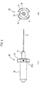
- FIG.4(a) is a side view of an optical connector ferrule
- FIG.4(b) is a front view of the optical connector ferrule when viewed from the short optical fiber side
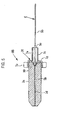
- FIG.5 is a longitudinal sectional view of the optical connector ferrule shown in FIG.4 .
- An optical connector of this embodiment can be applied to both the cord type in which an optical cord 70 is connected, and the coated fiber type in which a coated optical fiber 3 is connected.
- cord type optical connecter (referred simply to as the "optical connecter” hereinafter) 1 will be explained.
- the optical connector 1 of this embodiment is fitted to an exposed end portion of the coated optical fiber 3, from which a jacket 72 (see FIG.3 ) of the optical cord 70 on site is removed by a predetermined length.
- this optical connector 1 includes an SC connector knob 81, a plug frame 83, a fiber built-in ferrule (optical connector ferrule) 85, a protection sleeve 87 having thermal shrinkability, a ferrule presser bar spring 89, a rear housing 91, a caulking ring 93, and a boot 95 as principal members.
- the plug frame 83 houses and holds the optical connector ferrule 85 to which a short optical fiber 5 is fitted previously.
- the protection sleeve 87 covers an outer periphery of a fusion-spliced portion 13 (see FIG.3 ) of the coated optical fiber 3 and the short optical fiber 5 to protect the fusion-spliced portion 13.
- the rear housing 91 has an internal space 17 in which the protection sleeve 87 is arranged, and is integrated with a plug frame 9 when its top end is coupled to the plug frame 83.
- the boot 95 houses the end portion and its neighborhood of the coated optical fiber 3, which is fusion spliced to the short optical fiber 5, to protect the coated optical fiber 3. Also, the boot 95 is integrated with the rear housing 91 when its top end is coupled to a base end of the rear housing 91.
- the short optical fiber 5 is fitted such that its center axis is aligned with a top end shaft portion 7a in such a fashion that a diameter-extended portion 7b whose outer diameter is extended is provided in the rear of the top end shaft portion 7a that is butt connected to the optical connector ferrule on the opposite side.
- a sleeve coupling projection 7c used to couple the protection sleeve 87 described later is provided on the outer periphery on the base end side from which the short optical fiber 5 of the optical connector ferrule 85 is protruded.
- the top end shaft portion 7a of the zirconia ferrule acting as a ferrule main body is fitted into a concave portion formed in the diameter-extended portion 7b, and is coupled integrally to the diameter-extended portion 7b.
- An optical fiber insertion hole 7d as a fine hole into which the short optical fiber 5 is inserted to position is formed in the top end shaft portion (zirconia ferrule) 7a to pass therethrough.
- a hole 7e whose inner diameter is larger than the optical fiber insertion hole 7d is formed in the sleeve coupling projection 7c to extend to a concave portion of the diameter-extended portion 7b, and is communicated with the optical fiber insertion hole 7d. Also, an air escape hole 7f through which the concave portion of the diameter-extended portion 7b and the outside are communicated mutually is formed in the diameter-extended portion 7b of the optical connector ferrule 85.
- An optical fiber guiding portion 7g that is shaped into a taper surface to make the insertion of the short optical fiber 5 easy is formed on the fiber introducing side of the optical fiber insertion hole 7d into which the short optical fiber 5 is inserted.
- a notched groove 7h is formed in outer edges of the diameter-extended portion 7b in the diameter direction respectively. This notched groove 7h is used to prevent the turning of the ferrule main body and position this ferrule main body at a time of polishing.
- the assembly of the above optical connector ferrule 85 is done by inverting the short optical fiber 5 from the rear end side of the optical connector ferrule 85 and then arranging a glass fiber part 5b, which is exposed by striping off a coating 5a on the top end side, in the optical fiber insertion hole 7d.
- the position of the coating 5a is set in such a way that a top end portion of the coating 5a (a boundary part between the coating 5a and the glass fiber part 5b) is positioned in the optical fiber guiding portion 7g.
- the short optical fiber 5 is adhered/fixed by injecting an adhesive 10 into the optical fiber insertion hole 7d and the optical fiber guiding portion 7g.
- the adhesive 10 is not filled into the hole 7e of the sleeve coupling projection 7c not to adhere/fix the short optical fiber 5. Then, in order to fusion splice the short optical fiber 5 to the coated optical fiber 3 on the opposite site, the coating 5a of the end portion of the short optical fiber 5 extended from the rear end of the optical connector ferrule 85 is stripped off, and whereby the assembly is completed. That is, the coating 5a of the short optical fiber 5 exists at least in the hole 7e of the sleeve coupling projection 7c.
- the assembled optical connector ferrule 85 is inserted into an opening of the plug frame 83 on the base end side.
- the front end of the diameter- extended portion 7b comes in touch with a diameter-reduced portion 9a that is provided to protrude into the inner peripheral area of the plug frame 83, and thus the optical connector ferrule 85 is brought into a state that the its forward movement is restricted.
- the position of the optical connector ferrule 85 is restricted in a state that its top end is protruded from the top end of the plug frame 83 merely by a predetermined length L1
- a dust cap 22 is put on the top end of the optical connector ferrule 85 being positioned in the plug frame 83, and is fitted thereto.
- This dust cap 22 prevents such an event that a dust, and the like adhere to the fiber end surface during the safekeeping, or the like.
- the illustration of the dust cap 22 is omitted except FIG.1 .
- a mirror polishing is applied in advance to the top end surface of the optical connector ferrule 85, and thus the polishing process on the spot can be omitted.
- the ferrule presser bar spring 89 is inserted into the plug frame 83 into which the optical connector ferrule 85 is inserted.
- the ferrule presser bar spring 89 is formed of a compression coil spring that is put between the rear housing 91, which is engaged with the plug frame 83, and the diameter- extended portion 7b of the optical connector ferrule 85, and is held between them.
- the ferrule presser bar spring 89 brings the diameter-extended portion 7b of the optical connector ferrule 85 into contact with the diameter-reduced portion 9a of the plug frame 83, and simultaneously supports elastically this diameter-extended portion 7b to move backward.
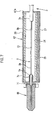
- FIG.6(a) is a longitudinal sectional view of the optical connector ferrule shown in FIG.5 and the protection sleeve connected to this optical connector ferrule
- FIG.6(b) is a cross sectional view of the protection sleeve taken along an A-A line in FIG.6(a)
- FIG.7 is a longitudinal sectional view of the protection sleeve prior to the thermal shrinking process.
- the protection sleeve 87 is illustrated in a slightly exaggerated manner with respect to the optical connector ferrule 85.
- the fusion-spliced portion 13 is formed by butting the part 5b in which the coating 5a is stripped at the end portion of the short optical fiber 5, and a part 3b in which a coating 3a is stripped at the end portion of the coated optical fiber 3, and then fusion splicing the butted fiber end surfaces.
- the end surface of the short optical fiber 5 from which the coating 5a is stripped is mirror-finished previously by either a cleavage caused by applying a bending stress to the optical fiber or the polishing, and thus the mirror polishing on the spot can be omitted.
- the edge of the end surface of the short optical fiber 5 should be cut by the electric- discharge machining before the fusion splicing. This is because a chipping produced from the edge by the polishing can be prevented. Further, the short optical fiber 5 is conveyed to the spot in a state that the coating is removed from the fiber. Therefore, it is preferable that the carbon-coated fiber should be employed as the short optical fiber 5. This is because a reduction of strength caused due to scratches or moisture absorption can be suppressed. Also, it is preferable that the short optical fiber 5 should be formed of the fiber whose MFD is reduced and which is tough to the bending.
- the protection sleeve 87 has a thermal shrinkage tube 25, a stem 27 that is passed through the thermal shrinkage tube 25, and an adhesive tube 29 (see FIG.7 ) through which the optical fiber is passed.
- the thermal shrinkage tube 25 is coupled onto the sleeve coupling projection 7c of the optical connector ferrule 85.
- the coated optical fiber 3 is fitted into the optical connector 1 in a state that the jacket 72 of the optical cord 70 is removed from the end portion by a predetermined length.
- the protection sleeve 87 covers the outer periphery of the coated optical fiber 3 on the other end side where the protection sleeve 87 is not coupled to the optical connector ferrule 85.
- the thermal shrinkage tube 25 When the thermal shrinkage tube 25 is heated up to a predetermined temperature by the heating machine, this tube thermally shrinks and adheres closely to the inserted stem 27. Also, the thermal shrinkage tube 25 thermally shrinks to cause the stem 27 to contact tightly to the sleeve coupling projection 7c of the optical connector ferrule 85, and also adheres closely to the outer periphery of the coated optical fiber 3. When both ends (parts that adhere closely to the optical connector ferrule 85 and the coated optical fiber 3 respectively) shrink quickly than the center portion in the axial direction while the thermal shrinkage tube 25 thermally shrinks, an air is confined in the protection sleeve 87 and the sleeve coupling projection 7c, and thus the bubbles are generated.
- one of characterizing structures of the present invention resides in that the air escape hole 7f is provided in the diameter-extended portion 7b of the optical connector ferrule 85. Accordingly, the remaining air in the sleeve can be escaped from the air escape hole 7f to the outside via the hole 7e in the sleeve coupling projection 7c and the concave portion in the diameter-extended portion 7b. Therefore, as shown in FIG.5 , the adhesive is not injected into the hole 7e in the sleeve coupling projection 7c, and the air flow path is intentionally ensured. As a result, the coating 5a is not stripped from the short optical fiber 5 that is kept in a non-adhered state, and the coating 5a still remains in the sleeve coupling projection 7c to keep the strength.
- the reason why the adhesive is not injected into the hole 7e in the sleeve coupling projection 7c is given as follows. That is, when the injection of the adhesive is not strictly managed while, upon assembling the optical connector ferrule 85, the adhesive is filled into the hole 7e in the sleeve coupling projection 7c to hold the inserted short optical fiber 5, the ununiform injection of the adhesive causes a difference in a curing/shrinking force around the fiber.
- the curing/shrinking force generated on the side where the more adhesive is injected becomes stronger than that generated on the side where the less adhesive is injected, and therefore the short optical fiber 5 leans to the inner wall side on which the more adhesive is injected in the internal space of the hole 7e. As a result, it is possible that a bend loss is caused in the short optical fiber 5.
- the characterizing structures of the present invention resides in that, as already described above, the short optical fiber 5 is held in the optical connector ferrule 85 by the adhesive 10 that is filled only in the optical fiber insertion hole 7d and the optical fiber guiding portion 7g of the optical connector ferrule 85. Accordingly, the short optical fiber 5 is never inclined in the internal space of the hole 7e, due to a difference in the curing/shrinking force of the adhesive. Also, even if the short optical fiber 5 is inclined to contact the inner wall surface of the hole 7e, the strength of the short optical fiber 5 can be still kept by the coating 5a.
- the adhesive tube 29 is softened by the heating that is applied in thermally shrinking the thermal shrinkage tube 25. This softened adhesive tube 29 serves as the adhesive that fills a clearance 34 between the thermal shrinkage tube 25 and the stem 27.
- the protection sleeve 87 positions the thermal shrinkage tube 25, the stem 27, and the adhesive tube 29 in a state that the end portion of the stem 27 and the end portion of the adhesive tube 29 are aligned in position with one end of the protection sleeve 87. Then, the protection sleeve 87 is fixed to the sleeve coupling projection 7c of the optical connector ferrule 85 in this positioned state. Both end portions of the adhesive tube 29 and the stem 27 may be press-fitted or be deposited onto the optical connector ferrule 85 instead of the adhesion, and may be fixed integrally with this ferrule.
- Respective length dimensions of the short optical fiber 5 and the thermal shrinkage tube 25, the stem 27, and the adhesive tube 29 of the protection sleeve 87 are set in such a way that, when the protection sleeve 87 is coupled to the sleeve coupling projection 7c on the base end of the optical connector ferrule 85, the fusion-spliced portion 13 is positioned just in the substantially middle position of the protection sleeve 87 in the length direction.
- the protection sleeve 87 is moved to cover the fusion- spliced portion 13 after the short optical fiber 5 and the coated optical fiber 3 are fusion spliced together, and is brought into contact with the optical connector ferrule 85. Then, the heat is applied to the thermal shrinkage tube 25 such that the coated optical fiber 3 and the short optical fiber 5 are fixed in a state that these components are put longitudinally along the stem 27. In this manner, dimensions of respective components are set in such a manner that, when the thermal shrinkage tube 25 is thermally shrunk, the end portion of the thermal shrinkage tube 25 overlaps with the coating 3a of the coated optical fiber 3 and the sleeve coupling projection 7c by 2 mm or more.
- the rear housing 91 is a cylindrical structure that covers the periphery of the protection sleeve 87, and is formed of resin in terms of the injection molding, or the like.
- the top end of the rear housing 91 constitutes a cylinder portion 91a that is fitted into the base end of the plug frame 83.
- an engaging claw 91b that engages with an engaged hole 83a, which is cut on the outer periphery of the base end of the plug frame 83, when the cylinder portion 91a is fitted into the base end of the plug frame 83 is provide to the cylinder portion 91a.
- the rear housing 91 is moved and put on the protection sleeve 87 after the protection sleeve 87 is subjected to the thermal shrinking process.
- the rear housing 91 is coupled integrally to the plug frame 83 by engaging the engaging claw 91b on the top end side with the engaged hole 83a of the plug frame 83.
- the SC connector knob 81 acting as the knob portion in connecting the connector is put on the outer periphery of the plug frame 83 to which the rear housing 91 is coupled, and fitted thereto.
- the SC connector knob 81 is an exterior component that provides an external appearance of the optical connector 1 on the top end side.
- a nonskid knurl 33a for facilitating the grasping of the knob is formed on both outer side surfaces of the SC connector knob 81.
- the boot 95 protects the optical cord 70 such that a sharp bending is not acted to the optical cord 70 that is extended to the rear side of the rear housing 91.
- the boot 95 is coupled integrally to the rear housing 91 when its top end is fitted onto or screwed onto the base end of the rear housing 91.
- the rear housing 91 may be formed integrally with the rear housing 91 by means of the resin injection molding.
- a space 35 (see FIG.3 ) for allowing the protection sleeve 87 to move back is formed between other, end 87a (see FIG.6 ) of the protection sleeve 87 and an inner wall end in the boot 95 opposing to this other end 87a.
- the boot 95 may be constructed such that a reinforcing tube 37 that is put on the optical cord 70 may be inserted into the backside of the inner wall end, and fitted thereon.
- a disconnection preventing portion 37a whose diameter is extended is provided to the top end of the reinforcing tube 37. Because the disconnection preventing portion 37a engages with the inner wall end in the boot 95, a moving action of the reinforcing tube 37 is restricted.
- the reinforcing tube 37 is formed of a tube that has adequate elasticity, and prevents such an event that the optical cord 70 is bent sharply.
- An orientation mark 97a is provided to the side surface of the diameter-extended portion 7b of the optical connector ferrule 85.
- an orientation mark 97b and a sight recess 99 are provided to the sidewall of the plug frame 83.
- the jacket 72 located on the end portion of the optical cord 70 is stripped largely. This is because the work in the fusion splice on site should be improved, upon fusion-splicing the short optical fiber 5 of the optical connector ferrule 85 and the coated optical fiber 3 that is exposed by removing the jacket 72 from the optical cord 70 on site.
- the coated optical fiber 3 whose outer periphery is covered with a high tensile-strength fiber (Kevlar (registered trademark)) 74 is exposed.
- the high tensile-strength fiber 74 and the jacket 72 are cut into a predetermined length, and are fitted into a rear end portion 91c of the rear housing 91.
- the caulking ring 93 is put on the outer periphery of the fitted jacket 72, and the caulking ring 93 is caulked in the diameter reducing direction. Since the diameter of the caulking ring 93 is decreased, the jacket 72 and the high tensile-strength fiber 74 are press-fitted into the caulking ring 93 and the rear end portion 91c, and are fixed to the rear housing 91.
- FIG.8 is a longitudinal sectional view showing a structure of a variation in which the optical connector shown in FIG.2 is applied to the coated fiber type.
- the optical connector 1 according to the present embodiment can also be employed as the coated fiber type.
- a shape of the SC connector knob 81 is slightly different and that the caulking ring 93 used to fix the high tensile-strength fiber 74 and the jacket 72 is not needed, remaining components in this variation are similar to those in the above embodiment.
- the reference numeral 37 denotes the reinforcing tube for the coated optical fiber 3.
- one end of the protection sleeve 87 is coupled to the optical connector ferrule 85. Therefore, the positioning of the protection sleeve 87 is made precisely, irrespective of a degree of skill of the worker on site. As a result, an overlapped length between the end portion of the protection sleeve 87 and the coated portion of the coated optical fiber 3 can be reduced up to about 3 mm, and thus a length of the optical connector 1 can be made compact by reducing largely a length of the protection sleeve 87. Therefore, on account of the compactification of the optical connector, the fittability of the optical connector 1 into the small-sized aerial closure, or the like can be improved.
- the protection sleeve 87 for covering the peripheries of the short optical fiber 5 and the fusion-spliced portion 13 is coupled to the optical connector ferrule 85.
- the protection sleeve 87 also moves back together with the optical connector ferrule 85.
- a large compressive load is never applied to the short optical fiber 5.
- it can be prevented that a large bending load is applied to the short optical fiber 5 being fitted to the optical connector ferrule 85, at a time of the connector connecting work.
- the problems of an increase of bend loss, a breakage, etc. of the optical fiber can be avoided.
- the optical connector 1 of the present embodiment is constructed such that the protection sleeve 87 includes the thermal shrinkage tube 25, and the stem 27 and the adhesive tube 29 both being passed through the thermal shrinkage tube 25, and also the protection sleeve 87 is coupled to the optical connector ferrule 85.
- the protection sleeve 87 is coupled to the sleeve coupling projection 7c of the optical connector ferrule 85, and then the protection sleeve 87 can hold firmly the fusion-spliced portion 13 between the short optical fiber 5 and the coated optical fiber 3 on site in a state that these components are put longitudinally along the stem 27, when such a simple operation that the thermal shrinkage tube 25 provided on its outer periphery is thermally shrunk by the heating process using the heating machine is applied.
- the fusion-spliced portion 13 can be reinforced strongly with the protection sleeve 87. In other words, the fusion-spliced portion 13 can be protected simply and firmly by the protection sleeve 87 even on the spot where it is difficult to get the working equipment, and the like ready.
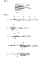
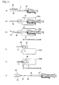
- FIG.10(a) to (e) are process charts explaining the procedures of assembling the optical connector shown in FIG.2
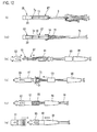
- FIG.11(f) to (k) are process charts explaining the procedures of assembling the optical connector shown in FIG.2
- FIG.12(l) to (q) are process charts explaining the procedures of assembling the optical connector shown in Fig.2 .
- first respective portions of the boot 95, the caulking ring 93, the rear housing 91, and the ferrule presser bar spring 89 are inserted in order into the end portion of the optical cord 70 on site.
- the jacket 72 on the top end side of the optical cord 70 is removed, and the extra high tensile-strength fiber 74 is cut away.
- a slit 103 is made in the jacket 72 in the axial direction to cut up the jacket 72.
- the jacket 72 and the exposed high tensile-strength fiber 74 are tucked up not to be a hindrance in the later operations.
- the protection sleeve 87 is slipped onto the coated optical fiber 3.
- the coating 3a is stripped from the coated optical fiber 3, which is extended from the protection sleeve 87, to expose the glass fiber part 3b, and then the part 3b is cleaned.
- the protection sleeve 87 and the coated optical fiber 3 are set in a fusion fiber holder 105A.
- the glass fiber part 3b is mirror-cut into a predetermined length, and then the protection sleeve 87 and the coated optical fiber 3 are set in the fusion splicing machine (not shown).
- the optical connector ferrule 85 in which the short optical fiber 5 is built is set in a ferrule holder 105B.
- a reference numeral 22 denotes the dust cap.
- the ferrule holder 105B that holds the optical connector ferrule 85 is set in the fusion splicing machine (not shown).
- the part 3b, in which the coating 3a is stripped, of the coated optical fiber 3 and the part 5b, in which the coating 5a is stripped, of the short optical fiber 5 in the optical connector ferrule 85 are butted together, and these stripped parts are fusion spliced together by the fusion splicing machine.
- the top end of the protection sleeve 87 is fitted onto the sleeve coupling projection 7c in the optical connector ferrule 85 to cover the fusion-spliced portion 13, and then the protection sleeve 87 is thermally shrunk. Then, as shown in FIG.12(m) , the tucked-up portions of the high tensile-strength fiber 74 and the jacket 72 are restored.
- the dust cap 22 is removed from the optical connector ferrule 85, then the plug frame 83 is inserted from the top end side of the optical connector ferrule, 85, and then the rear housing 91 is fitted into the plug frame 83 while holding the ferrule presser bar spring 99 therein. Then, as shown in FIG.12(o) , the high tensile-strength fiber 74 and the jacket 72 are put on the rear end portion 91c of the rear housing 91.
- the caulking ring 93 is press-fitted, and the high tensile-strength fiber 74 and the jacket 72 are fixed to the rear end portion 91c.
- the SC connector knob 81 and the boot 95 are coupled to the plug frame 83 and the rear housing 91 respectively, and thus the assembly of the optical connector 1 is completed.
Landscapes
- Physics & Mathematics (AREA)
- General Physics & Mathematics (AREA)
- Optics & Photonics (AREA)
- Engineering & Computer Science (AREA)
- Plasma & Fusion (AREA)
- Mechanical Coupling Of Light Guides (AREA)
Abstract
Description
- The present invention relates to an optical connector that houses and holds a fusion-spliced portion, in which a short optical fiber that is fitted previously to an optical connector ferrule and a coated optical fiber are fusion spliced together, therein,
- In the private optical cable, or the like, the optical connector must be fitted to the optical fiber cable on the spot,
- In the prior art, as one mode of the structures used to connect the optical connector ferrule to the end of the coated optical fiber on the spot, there is the optical connector shown in Patent Literature 1 (see
FIG.13 ).
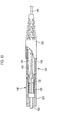
In anoptical connector 110 shown inPatent Literature 1, a shortoptical fiber 103 that is fitted in advance to anoptical connector ferrule 102, and a coatedoptical fiber 100 on site are connected by the fusion splicing. Then, the periphery of a fusion-splicedportion 105 is covered with aprotection sleeve 101 and is reinforced with it.
Then, aconnector housing 121 has such a configuration that this housing can house respective elements from theoptical connector ferrule 102 to a part of the coatedoptical fiber 100 located in the rear of theprotection sleeve 101.
Also, theconnector housing 121 has aplug frame 122 for housing theoptical connector ferrule 102 in a state that its top end is projected, aboot 123 for housing an end portion of the coatedoptical fiber 100, and acylindrical stop ring 124 whose one end is fitted into theplug frame 122 and integrated with this plug frame and whose other end is fitted into theboot 123 and integrated with this boot. Theoptical connector ferrule 102 located in theplug frame 122 is energized to the top end side by acompression coil spring 125. Thiscompression coil spring 125 keeps a contact pressure between theoptical connector ferrule 102 and the optical connector ferrule on the opposite-side optical connector within a specified range, while allowing theoptical connector ferrule 102 to move back at a time of connecting the connector. - In connecting the coated optical fiber end and the optical connector ferrule in the above
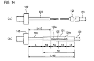
optical connector 110, the end portion of the coatedoptical fiber 100 on site, from which the connector housing is omitted as shown inFIG.14(a) , is inserted previously into theprotection sleeve 101 that protects the fusion-spliced portion. Then, respective coatings of the end portion of the shortoptical fiber 103, which is fitted previously to theoptical connector ferrule 102 being held in the plug frame such as the SC connector, or the like, and the end portion of the coatedoptical fiber 100 are stripped over a predetermined length. Then, respective stripped end portions are butt connected mutually, and then are fusion spliced together. Then, as shown inFIG.14(b) , theprotection sleeve 101 being fitted on the coatedoptical fiber 100 is moved onto the fusion-splicedportion 105 such that the fusion- splicedportion 105 is covered with theprotection sleeve 101 and is brought into a reinforced state. As a result, theoptical connector 110 can protect the fusion-splicedportion 105 without fail. -
- Patent Literature 1: Japanese Patent Application Publication:
JP-A-2002-82257 - However, on account of the alignment and the positioning using the jig, a length of coating-stripped
parts protection sleeve 101 to cover surely the coated portion of each optical fiber, a length of theprotection sleeve 101 must be set such that the coated portion of each optical fiber and theprotection sleeve 101 are overlapped with each other by about 10 mm. - That is, a length of the
protection sleeve 101 exceeds 40 mm or more. As a result, theoptical connector 110 is extended to exceed L+40 mm that contains a length L of the exposed coated portion of the shortoptical fiber 103 and alength 40 mm of theprotection sleeve 101. In some cases, it is difficult to ensure an enough housing space, and it becomes difficult to install the fusion-spliced portion into a small-sized cabinet, or the like.
Here, it may be considered that, in order to prevent the extension of theoptical connector 110, a length dimension of theprotection sleeve 101 should be shortened.
In this case, the fixed position of theprotection sleeve 101 is displaced in the axial direction due to skill difference, wrong work, etc. of the worker on site, and therefore there is a risk that the bare optical fiber is exposed. For this reason, an overlapped length of the protection sleeve 101 onto the coated portion of each coated optical fiber cannot be shortened so much.
Therefore, such a problem still remains that the above approach has little effect on the shortening of theprotection sleeve 101, or the like, and also it is difficult to fit the fusion-spliced portion into the cabinet, or the like. - Further, in the case of the above
optical connector 110, upon manufacturing the optical connector, the periphery of the fusion-splicedportion 105 is covered with theprotection sleeve 101 made of the thermal shrinkage material, while applying the heating to cause the shrinkage. At that time, in some cases an air is confined in the protection sleeve, and bubbles are generated to cause a bending stress in the optical fiber. - It is an object of the present invention to provide an optical connector capable of improving fittability into a small-sized cabinet, or the like and also avoiding problems of an increase of bend loss, a breakage, etc. of an optical fiber.
- In order to achieve the object, an optical connector according to the present invention is an optical connector for housing and holding a fusion-spliced portion, in which a short optical fiber that is fitted to an optical connector ferrule and a coated optical fiber are fusion spliced together, herein,
wherein one end of a protection sleeve made of a thermal shrinkage material, which is slipped onto the short optical fiber and the coated optical fiber and covers a periphery of the fusion-spliced portion, is coupled to the optical connector ferrule, and an air escape hole that is communicated with an inside of the protection sleeve is provided in the optical connector ferrule. - In the optical connector according to the present invention, it is preferable that a top end portion, in which a coating is stripped, of the short optical fiber is inserted into an optical fiber insertion hole of the optical connector ferrule, and a boundary part between the top end portion and the coating is adhered and secured to the optical fiber insertion hole.
- In the optical connector according to the present invention, it is preferable that the optical connector ferrule has a ferrule main body, a diameter extended portion which is coupled integrally to the ferrule main body, and a coupling projection which is joined to one end of the diameter-extended portion and onto which the protection sleeve is fitted, and
the coating which is stripped from the top end portion and removed from the fusion-spliced portion of the short optical fiber is still left at least in the coupling projection. - According to the optical connector of the present invention, one end of the protection sleeve is coupled to the optical connector ferrule. Therefore, the positioning of the protection sleeve that sets the fusion-spliced portion in the center position is made precisely, irrespective of a degree of skill of the worker on site. As a result, an overlapped length between the end portion of the protection sleeve and the coated portion of the coated optical fiber can be reduced, and thus a length of the optical connector can be made compact by reducing largely a length of the protection sleeve.
Therefore, on account of the compactification of the optical connector, the fittability of the optical connector into the small-sized cabinet, or the like can be improved. - Also, the air escape hole that communicates with the inside of the protection sleeve is provided to the optical connector ferrule to which the protection sleeve is coupled. Therefore, even though an air is confined in the protection sleeve made of the thermal shrinkage material when this protection sleeve is arranged over the fusion-spliced portion and is thermally shrunk, the confined air can be exhausted to the outside through this air escape hole.
As a result, such an event never happens that a bending stress is caused in the optical fiber due to the remaining of bubbles in the protection sleeve. -
-
FIG.1 is a perspective external view of an embodiment of an optical connector according to the present invention. -
FIG.2 is an exploded side view of the embodiment of the optical connector according to the present invention. -
FIG.3(a) is a longitudinal sectional view of the optical connector shown inFIG.2 , andFIG.3(b) is a pertinent longitudinal sectional view of a variation in which a reinforcing tube is fitted. -
FIG.4(a) is a side view of an optical connector ferrule, andFIG.4(b) is a front view of the optical connector ferrule, when viewed from the short optical fiber side. -
FIG.5 is a longitudinal sectional view of the optical connector ferrule shown inFIG.4 . -
FIG.6(a) is a longitudinal sectional view of the optical connector ferrule shown inFIG.4 , andFIG.6(b) is a cross sectional view of the protection sleeve connected to the optical connector ferrule -
FIG.7 is a longitudinal sectional view of the protection sleeve prior to the thermal shrinking process. -
FIG.8 is a longitudinal sectional view showing a structure of a variation in which the optical connector shown inFIG.2 is applied to the coated fiber type. -
FIG.9 is a longitudinal sectional view of the optical connector ferrule in which the adhesive is injected ununiformly. -
FIG.10(a) to (e) are process charts explaining the procedures of assembling the optical connector shown inFIG.2 . -
FIG.11(f) to (k) are process charts explaining the procedures of assembling the optical connector shown inFIG.2 . -
FIG.12(l) to (q) are process charts explaining the procedures of assembling the optical connector shown inFIG.2 . -
FIG.13 is a view explaining a prior art structure that a short optical fiber that is fitted in advance to an optical connector ferrule, and a coated optical fiber are connected by the fusion splicing.. -
FIG.14 is a view explaining a prior art optical connector. - 1: optical connector, 3: coated optical fiber, 5: short optical fiber, 7a: top end shaft portion (ferrule main body), 7b: diameter-extended portion, 7c: sleeve coupling projection (coupling projection), 7d: optical fiber insertion hole, 7e: hole, 7f: air escape hole, 7g: optical fiber guiding portion, 13: fusion-spliced portion, 25: thermal shrinkage tube, 70: optical cord, 83: plug frame, 85: optical connector ferrule, 87: protection sleeve, 95: boot
- A preferred embodiment of an optical connector according to the present invention will be explained in detail with reference to the drawings hereinafter.
FIG.1 is a perspective external view of an embodiment of an optical connector according to the present invention,FIG.2 is an exploded side view of the optical connector shown inFIG. 1 ,FIG.3(a) is a longitudinal sectional view of the optical connector shown inFIG.1 ,FIG.3(b) is a pertinent longitudinal sectional view of a variation in which a reinforcing tube is fitted,FIG.4(a) is a side view of an optical connector ferrule,FIG.4(b) is a front view of the optical connector ferrule when viewed from the short optical fiber side, andFIG.5 is a longitudinal sectional view of the optical connector ferrule shown inFIG.4 .
An optical connector of this embodiment can be applied to both the cord type in which anoptical cord 70 is connected, and the coated fiber type in which a coatedoptical fiber 3 is connected. Except that a shape of the SC connector knob described later is slightly different, respective components that are substantially common to those of the cord type optical connecter are employed in the coated fiber type optical connecter. In the following explanation, mainly the cord type optical connecter (referred simply to as the "optical connecter" hereinafter) 1 will be explained. - The
optical connector 1 of this embodiment is fitted to an exposed end portion of the coatedoptical fiber 3, from which a jacket 72 (seeFIG.3 ) of theoptical cord 70 on site is removed by a predetermined length. From its top end side (the left side inFIG.2 ) coupled to the opposite side optical connector, thisoptical connector 1 includes anSC connector knob 81, aplug frame 83, a fiber built-in ferrule (optical connector ferrule) 85, aprotection sleeve 87 having thermal shrinkability, a ferrulepresser bar spring 89, arear housing 91, acaulking ring 93, and aboot 95 as principal members. - An outline of the above principal members will be described hereinafter. The
plug frame 83 houses and holds theoptical connector ferrule 85 to which a shortoptical fiber 5 is fitted previously. Theprotection sleeve 87 covers an outer periphery of a fusion-spliced portion 13 (seeFIG.3 ) of the coatedoptical fiber 3 and the shortoptical fiber 5 to protect the fusion-splicedportion 13. Therear housing 91 has aninternal space 17 in which theprotection sleeve 87 is arranged, and is integrated with a plug frame 9 when its top end is coupled to theplug frame 83. Theboot 95 houses the end portion and its neighborhood of the coatedoptical fiber 3, which is fusion spliced to the shortoptical fiber 5, to protect the coatedoptical fiber 3. Also, theboot 95 is integrated with therear housing 91 when its top end is coupled to a base end of therear housing 91. - Further, details of the above principal members will be described hereunder. In the
optical connector ferrule 85, the shortoptical fiber 5 is fitted such that its center axis is aligned with a topend shaft portion 7a in such a fashion that a diameter-extendedportion 7b whose outer diameter is extended is provided in the rear of the topend shaft portion 7a that is butt connected to the optical connector ferrule on the opposite side. Also, asleeve coupling projection 7c used to couple theprotection sleeve 87 described later is provided on the outer periphery on the base end side from which the shortoptical fiber 5 of theoptical connector ferrule 85 is protruded. - As shown in
FIG.4 andFIG.5 , in theoptical connector ferrule 85, the topend shaft portion 7a of the zirconia ferrule acting as a ferrule main body is fitted into a concave portion formed in the diameter-extendedportion 7b, and is coupled integrally to the diameter-extendedportion 7b. An opticalfiber insertion hole 7d as a fine hole into which the shortoptical fiber 5 is inserted to position is formed in the top end shaft portion (zirconia ferrule) 7a to pass therethrough. Ahole 7e whose inner diameter is larger than the opticalfiber insertion hole 7d is formed in thesleeve coupling projection 7c to extend to a concave portion of the diameter-extendedportion 7b, and is communicated with the opticalfiber insertion hole 7d. Also, anair escape hole 7f through which the concave portion of the diameter-extendedportion 7b and the outside are communicated mutually is formed in the diameter-extendedportion 7b of theoptical connector ferrule 85. An opticalfiber guiding portion 7g that is shaped into a taper surface to make the insertion of the shortoptical fiber 5 easy is formed on the fiber introducing side of the opticalfiber insertion hole 7d into which the shortoptical fiber 5 is inserted. Also, as shown inFIG.4(b) , a notchedgroove 7h is formed in outer edges of the diameter-extendedportion 7b in the diameter direction respectively. This notchedgroove 7h is used to prevent the turning of the ferrule main body and position this ferrule main body at a time of polishing. - The assembly of the above
optical connector ferrule 85 is done by inverting the shortoptical fiber 5 from the rear end side of theoptical connector ferrule 85 and then arranging aglass fiber part 5b, which is exposed by striping off acoating 5a on the top end side, in the opticalfiber insertion hole 7d. At that time, as shown inFIG.5 , the position of thecoating 5a is set in such a way that a top end portion of thecoating 5a (a boundary part between thecoating 5a and theglass fiber part 5b) is positioned in the opticalfiber guiding portion 7g. Then, the shortoptical fiber 5 is adhered/fixed by injecting an adhesive 10 into the opticalfiber insertion hole 7d and the opticalfiber guiding portion 7g. In this case, the adhesive 10 is not filled into thehole 7e of thesleeve coupling projection 7c not to adhere/fix the shortoptical fiber 5. Then, in order to fusion splice the shortoptical fiber 5 to the coatedoptical fiber 3 on the opposite site, thecoating 5a of the end portion of the shortoptical fiber 5 extended from the rear end of theoptical connector ferrule 85 is stripped off, and whereby the assembly is completed. That is, thecoating 5a of the shortoptical fiber 5 exists at least in thehole 7e of thesleeve coupling projection 7c. - The assembled
optical connector ferrule 85 is inserted into an opening of theplug frame 83 on the base end side. At that time, as shown inFIG.3 , the front end of the diameter- extendedportion 7b comes in touch with a diameter-reduced portion 9a that is provided to protrude into the inner peripheral area of theplug frame 83, and thus theoptical connector ferrule 85 is brought into a state that the its forward movement is restricted. In this state, the position of theoptical connector ferrule 85 is restricted in a state that its top end is protruded from the top end of theplug frame 83 merely by a predetermined length L1, - Then, a
dust cap 22 is put on the top end of theoptical connector ferrule 85 being positioned in theplug frame 83, and is fitted thereto. Thisdust cap 22 prevents such an event that a dust, and the like adhere to the fiber end surface during the safekeeping, or the like. The illustration of thedust cap 22 is omitted exceptFIG.1 .
In this case, a mirror polishing is applied in advance to the top end surface of theoptical connector ferrule 85, and thus the polishing process on the spot can be omitted. - The ferrule
presser bar spring 89 is inserted into theplug frame 83 into which theoptical connector ferrule 85 is inserted. The ferrulepresser bar spring 89 is formed of a compression coil spring that is put between therear housing 91, which is engaged with theplug frame 83, and the diameter- extendedportion 7b of theoptical connector ferrule 85, and is held between them. The ferrulepresser bar spring 89 brings the diameter-extendedportion 7b of theoptical connector ferrule 85 into contact with the diameter-reduced portion 9a of theplug frame 83, and simultaneously supports elastically this diameter-extendedportion 7b to move backward. -
FIG.6(a) is a longitudinal sectional view of the optical connector ferrule shown inFIG.5 and the protection sleeve connected to this optical connector ferrule,FIG.6(b) is a cross sectional view of the protection sleeve taken along an A-A line inFIG.6(a) , andFIG.7 is a longitudinal sectional view of the protection sleeve prior to the thermal shrinking process. Here, inFIG.7 , in order to clarify the thermal shrinkage action, theprotection sleeve 87 is illustrated in a slightly exaggerated manner with respect to theoptical connector ferrule 85.
The fusion-splicedportion 13 is formed by butting thepart 5b in which thecoating 5a is stripped at the end portion of the shortoptical fiber 5, and apart 3b in which acoating 3a is stripped at the end portion of the coatedoptical fiber 3, and then fusion splicing the butted fiber end surfaces.
Here, the end surface of the shortoptical fiber 5 from which thecoating 5a is stripped is mirror-finished previously by either a cleavage caused by applying a bending stress to the optical fiber or the polishing, and thus the mirror polishing on the spot can be omitted. - Also, it is preferable that the edge of the end surface of the short
optical fiber 5 should be cut by the electric- discharge machining before the fusion splicing. This is because a chipping produced from the edge by the polishing can be prevented. Further, the shortoptical fiber 5 is conveyed to the spot in a state that the coating is removed from the fiber. Therefore, it is preferable that the carbon-coated fiber should be employed as the shortoptical fiber 5. This is because a reduction of strength caused due to scratches or moisture absorption can be suppressed. Also, it is preferable that the shortoptical fiber 5 should be formed of the fiber whose MFD is reduced and which is tough to the bending. - As shown in
FIG.6(b) , theprotection sleeve 87 has athermal shrinkage tube 25, astem 27 that is passed through thethermal shrinkage tube 25, and an adhesive tube 29 (seeFIG.7 ) through which the optical fiber is passed. Thethermal shrinkage tube 25 is coupled onto thesleeve coupling projection 7c of theoptical connector ferrule 85. The coatedoptical fiber 3 is fitted into theoptical connector 1 in a state that thejacket 72 of theoptical cord 70 is removed from the end portion by a predetermined length. Theprotection sleeve 87 covers the outer periphery of the coatedoptical fiber 3 on the other end side where theprotection sleeve 87 is not coupled to theoptical connector ferrule 85. - When the
thermal shrinkage tube 25 is heated up to a predetermined temperature by the heating machine, this tube thermally shrinks and adheres closely to the insertedstem 27. Also, thethermal shrinkage tube 25 thermally shrinks to cause thestem 27 to contact tightly to thesleeve coupling projection 7c of theoptical connector ferrule 85, and also adheres closely to the outer periphery of the coatedoptical fiber 3.
When both ends (parts that adhere closely to theoptical connector ferrule 85 and the coatedoptical fiber 3 respectively) shrink quickly than the center portion in the axial direction while thethermal shrinkage tube 25 thermally shrinks, an air is confined in theprotection sleeve 87 and thesleeve coupling projection 7c, and thus the bubbles are generated. - As described previously, one of characterizing structures of the present invention resides in that the
air escape hole 7f is provided in the diameter-extendedportion 7b of theoptical connector ferrule 85. Accordingly, the remaining air in the sleeve can be escaped from theair escape hole 7f to the outside via thehole 7e in thesleeve coupling projection 7c and the concave portion in the diameter-extendedportion 7b. Therefore, as shown inFIG.5 , the adhesive is not injected into thehole 7e in thesleeve coupling projection 7c, and the air flow path is intentionally ensured. As a result, thecoating 5a is not stripped from the shortoptical fiber 5 that is kept in a non-adhered state, and thecoating 5a still remains in thesleeve coupling projection 7c to keep the strength. - Also, the reason why the adhesive is not injected into the
hole 7e in thesleeve coupling projection 7c is given as follows. That is, when the injection of the adhesive is not strictly managed while, upon assembling theoptical connector ferrule 85, the adhesive is filled into thehole 7e in thesleeve coupling projection 7c to hold the inserted shortoptical fiber 5, the ununiform injection of the adhesive causes a difference in a curing/shrinking force around the fiber. Thus, as shown inFIG.9 , the curing/shrinking force generated on the side where the more adhesive is injected becomes stronger than that generated on the side where the less adhesive is injected, and therefore the shortoptical fiber 5 leans to the inner wall side on which the more adhesive is injected in the internal space of thehole 7e. As a result, it is possible that a bend loss is caused in the shortoptical fiber 5. - Therefore, the characterizing structures of the present invention resides in that, as already described above, the short
optical fiber 5 is held in theoptical connector ferrule 85 by the adhesive 10 that is filled only in the opticalfiber insertion hole 7d and the opticalfiber guiding portion 7g of theoptical connector ferrule 85. Accordingly, the shortoptical fiber 5 is never inclined in the internal space of thehole 7e, due to a difference in the curing/shrinking force of the adhesive. Also, even if the shortoptical fiber 5 is inclined to contact the inner wall surface of thehole 7e, the strength of the shortoptical fiber 5 can be still kept by thecoating 5a.
Here, theadhesive tube 29 is softened by the heating that is applied in thermally shrinking thethermal shrinkage tube 25. This softenedadhesive tube 29 serves as the adhesive that fills aclearance 34 between thethermal shrinkage tube 25 and thestem 27. - As shown in
FIG.7 , theprotection sleeve 87 positions thethermal shrinkage tube 25, thestem 27, and theadhesive tube 29 in a state that the end portion of thestem 27 and the end portion of theadhesive tube 29 are aligned in position with one end of theprotection sleeve 87. Then, theprotection sleeve 87 is fixed to thesleeve coupling projection 7c of theoptical connector ferrule 85 in this positioned state.
Both end portions of theadhesive tube 29 and thestem 27 may be press-fitted or be deposited onto theoptical connector ferrule 85 instead of the adhesion, and may be fixed integrally with this ferrule. - Respective length dimensions of the short
optical fiber 5 and thethermal shrinkage tube 25, thestem 27, and theadhesive tube 29 of theprotection sleeve 87 are set in such a way that, when theprotection sleeve 87 is coupled to thesleeve coupling projection 7c on the base end of theoptical connector ferrule 85, the fusion-splicedportion 13 is positioned just in the substantially middle position of theprotection sleeve 87 in the length direction. - The
protection sleeve 87 is moved to cover the fusion- splicedportion 13 after the shortoptical fiber 5 and the coatedoptical fiber 3 are fusion spliced together, and is brought into contact with theoptical connector ferrule 85. Then, the heat is applied to thethermal shrinkage tube 25 such that the coatedoptical fiber 3 and the shortoptical fiber 5 are fixed in a state that these components are put longitudinally along thestem 27.
In this manner, dimensions of respective components are set in such a manner that, when thethermal shrinkage tube 25 is thermally shrunk, the end portion of thethermal shrinkage tube 25 overlaps with thecoating 3a of the coatedoptical fiber 3 and thesleeve coupling projection 7c by 2 mm or more. - The
rear housing 91 is a cylindrical structure that covers the periphery of theprotection sleeve 87, and is formed of resin in terms of the injection molding, or the like. The top end of therear housing 91 constitutes acylinder portion 91a that is fitted into the base end of theplug frame 83. Then, an engagingclaw 91b that engages with anengaged hole 83a, which is cut on the outer periphery of the base end of theplug frame 83, when thecylinder portion 91a is fitted into the base end of theplug frame 83 is provide to thecylinder portion 91a.
Therear housing 91 is moved and put on theprotection sleeve 87 after theprotection sleeve 87 is subjected to the thermal shrinking process. Then, therear housing 91 is coupled integrally to theplug frame 83 by engaging the engagingclaw 91b on the top end side with the engagedhole 83a of theplug frame 83. - The
SC connector knob 81 acting as the knob portion in connecting the connector is put on the outer periphery of theplug frame 83 to which therear housing 91 is coupled, and fitted thereto. TheSC connector knob 81 is an exterior component that provides an external appearance of theoptical connector 1 on the top end side. Anonskid knurl 33a for facilitating the grasping of the knob is formed on both outer side surfaces of theSC connector knob 81. - The
boot 95 protects theoptical cord 70 such that a sharp bending is not acted to theoptical cord 70 that is extended to the rear side of therear housing 91. Theboot 95 is coupled integrally to therear housing 91 when its top end is fitted onto or screwed onto the base end of therear housing 91.
In this case, therear housing 91 may be formed integrally with therear housing 91 by means of the resin injection molding. - A space 35 (see
FIG.3 ) for allowing theprotection sleeve 87 to move back is formed between other,end 87a (seeFIG.6 ) of theprotection sleeve 87 and an inner wall end in theboot 95 opposing to thisother end 87a.
In this case, as shown inFIG.3(b) , theboot 95 may be constructed such that a reinforcingtube 37 that is put on theoptical cord 70 may be inserted into the backside of the inner wall end, and fitted thereon.
Adisconnection preventing portion 37a whose diameter is extended is provided to the top end of the reinforcingtube 37. Because thedisconnection preventing portion 37a engages with the inner wall end in theboot 95, a moving action of the reinforcingtube 37 is restricted. The reinforcingtube 37 is formed of a tube that has adequate elasticity, and prevents such an event that theoptical cord 70 is bent sharply. - An
orientation mark 97a is provided to the side surface of the diameter-extendedportion 7b of theoptical connector ferrule 85. In contrast, anorientation mark 97b and asight recess 99 are provided to the sidewall of theplug frame 83. When theorientation mark 97b is aligned with theorientation mark 97a while checking theorientation mark 97a through thesight recess 99, theoptical connector ferrule 85 can be fitted into theplug frame 83 in a normal attitude. - In the
optical connector 1, thejacket 72 located on the end portion of theoptical cord 70 is stripped largely. This is because the work in the fusion splice on site should be improved, upon fusion-splicing the shortoptical fiber 5 of theoptical connector ferrule 85 and the coatedoptical fiber 3 that is exposed by removing thejacket 72 from theoptical cord 70 on site. When thejacket 72 located on the end portion is stripped (removed) from theoptical cord 70, the coatedoptical fiber 3 whose outer periphery is covered with a high tensile-strength fiber (Kevlar (registered trademark)) 74 is exposed. - The high tensile-
strength fiber 74 and thejacket 72 are cut into a predetermined length, and are fitted into arear end portion 91c of therear housing 91. Thecaulking ring 93 is put on the outer periphery of the fittedjacket 72, and thecaulking ring 93 is caulked in the diameter reducing direction. Since the diameter of thecaulking ring 93 is decreased, thejacket 72 and the high tensile-strength fiber 74 are press-fitted into thecaulking ring 93 and therear end portion 91c, and are fixed to therear housing 91. -
FIG.8 is a longitudinal sectional view showing a structure of a variation in which the optical connector shown inFIG.2 is applied to the coated fiber type.
As already described above, theoptical connector 1 according to the present embodiment can also be employed as the coated fiber type. In this case, except that a shape of theSC connector knob 81 is slightly different and that thecaulking ring 93 used to fix the high tensile-strength fiber 74 and thejacket 72 is not needed, remaining components in this variation are similar to those in the above embodiment. Here, inFIG.8 , thereference numeral 37 denotes the reinforcing tube for the coatedoptical fiber 3. - According to the
optical connector 1 explained in the above, one end of theprotection sleeve 87 is coupled to theoptical connector ferrule 85. Therefore, the positioning of theprotection sleeve 87 is made precisely, irrespective of a degree of skill of the worker on site. As a result, an overlapped length between the end portion of theprotection sleeve 87 and the coated portion of the coatedoptical fiber 3 can be reduced up to about 3 mm, and thus a length of theoptical connector 1 can be made compact by reducing largely a length of theprotection sleeve 87.
Therefore, on account of the compactification of the optical connector, the fittability of theoptical connector 1 into the small-sized aerial closure, or the like can be improved. - Also, the
protection sleeve 87 for covering the peripheries of the shortoptical fiber 5 and the fusion-splicedportion 13 is coupled to theoptical connector ferrule 85. When theoptical connector ferrule 85 comes into contact with the optical connector ferrule on the opposite side and moves back during connecting the connector, theprotection sleeve 87 also moves back together with theoptical connector ferrule 85. Hence, a large compressive load is never applied to the shortoptical fiber 5.
As a result, it can be prevented that a large bending load is applied to the shortoptical fiber 5 being fitted to theoptical connector ferrule 85, at a time of the connector connecting work. Also, the problems of an increase of bend loss, a breakage, etc. of the optical fiber can be avoided. - Also, the
optical connector 1 of the present embodiment is constructed such that theprotection sleeve 87 includes thethermal shrinkage tube 25, and thestem 27 and theadhesive tube 29 both being passed through thethermal shrinkage tube 25, and also theprotection sleeve 87 is coupled to theoptical connector ferrule 85. - Then, one end of the
protection sleeve 87 is coupled to thesleeve coupling projection 7c of theoptical connector ferrule 85, and then theprotection sleeve 87 can hold firmly the fusion-splicedportion 13 between the shortoptical fiber 5 and the coatedoptical fiber 3 on site in a state that these components are put longitudinally along thestem 27, when such a simple operation that thethermal shrinkage tube 25 provided on its outer periphery is thermally shrunk by the heating process using the heating machine is applied. As a result, the fusion-splicedportion 13 can be reinforced strongly with theprotection sleeve 87.
In other words, the fusion-splicedportion 13 can be protected simply and firmly by theprotection sleeve 87 even on the spot where it is difficult to get the working equipment, and the like ready. - Next, procedures of assembling the
optical connector 1 having the above structure will be explained hereunder.
FIG.10(a) to (e) are process charts explaining the procedures of assembling the optical connector shown inFIG.2 ,FIG.11(f) to (k) are process charts explaining the procedures of assembling the optical connector shown inFIG.2 , andFIG.12(l) to (q) are process charts explaining the procedures of assembling the optical connector shown inFig.2 .
In assembling theoptical connector 1, as shown, inFIG.10(a) , first respective portions of theboot 95, thecaulking ring 93, therear housing 91, and the ferrulepresser bar spring 89 are inserted in order into the end portion of theoptical cord 70 on site. - Then, as shown in
FIG.10(b) , thejacket 72 on the top end side of theoptical cord 70 is removed, and the extra high tensile-strength fiber 74 is cut away. Then, as shown inFIG.10(c) , aslit 103 is made in thejacket 72 in the axial direction to cut up thejacket 72. Then, as shown inFIG.10(d) , thejacket 72 and the exposed high tensile-strength fiber 74 are tucked up not to be a hindrance in the later operations. Then, as shown inFIG.10(e) , theprotection sleeve 87 is slipped onto the coatedoptical fiber 3. - Then, as shown in
FIG.11(f) , thecoating 3a is stripped from the coatedoptical fiber 3, which is extended from theprotection sleeve 87, to expose theglass fiber part 3b, and then thepart 3b is cleaned. Then, as shown inFIG.11(g) , theprotection sleeve 87 and the coatedoptical fiber 3 are set in afusion fiber holder 105A. Then, as shown inFIG.11(h) , theglass fiber part 3b is mirror-cut into a predetermined length, and then theprotection sleeve 87 and the coatedoptical fiber 3 are set in the fusion splicing machine (not shown). - Meanwhile, as shown in
FIG.11(i) , theoptical connector ferrule 85 in which the shortoptical fiber 5 is built is set in aferrule holder 105B. Here, inFIG.11(i) , areference numeral 22 denotes the dust cap. Then, as shown inFIG.11(j) , theferrule holder 105B that holds theoptical connector ferrule 85 is set in the fusion splicing machine (not shown). Then, as shown inFIG.11(k) , thepart 3b, in which thecoating 3a is stripped, of the coatedoptical fiber 3 and thepart 5b, in which thecoating 5a is stripped, of the shortoptical fiber 5 in theoptical connector ferrule 85 are butted together, and these stripped parts are fusion spliced together by the fusion splicing machine. - Then, as shown in
FIG.12(l) , the top end of theprotection sleeve 87 is fitted onto thesleeve coupling projection 7c in theoptical connector ferrule 85 to cover the fusion-splicedportion 13, and then theprotection sleeve 87 is thermally shrunk. Then, as shown inFIG.12(m) , the tucked-up portions of the high tensile-strength fiber 74 and thejacket 72 are restored. - Then, as shown in
FIG.12(n) , thedust cap 22 is removed from theoptical connector ferrule 85, then theplug frame 83 is inserted from the top end side of the optical connector ferrule, 85, and then therear housing 91 is fitted into theplug frame 83 while holding the ferrulepresser bar spring 99 therein. Then, as shown inFIG.12(o) , the high tensile-strength fiber 74 and thejacket 72 are put on therear end portion 91c of therear housing 91. - Then, as shown in
FIG.12(p) , thecaulking ring 93 is press-fitted, and the high tensile-strength fiber 74 and thejacket 72 are fixed to therear end portion 91c. Finally, theSC connector knob 81 and theboot 95 are coupled to theplug frame 83 and therear housing 91 respectively, and thus the assembly of theoptical connector 1 is completed. - The present invention is explained in detail with reference to the particular embodiments as above. But it is apparent for those skilled in the art that various variations and modifications can be applied without departing from a spirit and a scope of the present invention.
This application is based upon Japanese Patent Application (Patent Application No.2008-050009
Claims (3)
- An optical connector for housing and holding a fusion-spliced portion, in which a short optical fiber that is fitted to an optical connector ferrule and a coated optical fiber are fusion spliced together, therein,
wherein one end of a protection sleeve made of a thermal shrinkage material, which is slipped onto the short optical fiber and the coated optical fiber and covers a periphery of the fusion-spliced portion, is coupled to the optical connector ferrule, and an air escape hole that is communicated with an inside of the protection sleeve is provided in the optical connector ferrule. - An optical connector according to claim 1, wherein a top end portion, in which a coating is stripped, of the short optical fiber is inserted into an optical fiber insertion hole of the optical connector ferrule, and a boundary part between the top end portion and the coating is adhered and secured to the optical fiber insertion hole.
- An optical connector according to claim 1 or 2, wherein the optical connector ferrule has a ferrule main body, a diameter extended portion which is coupled integrally to the ferrule main body, and a coupling projection which is joined to one end of the diameter-extended portion and onto which the protection sleeve is fitted, and
the coating which is stripped from the top end portion and removed from the fusion-spliced portion of the short optical fiber is still left at least in the coupling projection.
Applications Claiming Priority (2)
| Application Number | Priority Date | Filing Date | Title |
|---|---|---|---|
| JP2008050009A JP4719755B2 (en) | 2008-02-29 | 2008-02-29 | Optical connector |
| PCT/JP2008/073019 WO2009107306A1 (en) | 2008-02-29 | 2008-12-17 | Optical connector |
Publications (3)
| Publication Number | Publication Date |
|---|---|
| EP2249189A1 true EP2249189A1 (en) | 2010-11-10 |
| EP2249189A4 EP2249189A4 (en) | 2014-12-17 |
| EP2249189B1 EP2249189B1 (en) | 2017-08-16 |
Family
ID=41015713
Family Applications (1)
| Application Number | Title | Priority Date | Filing Date |
|---|---|---|---|
| EP08872849.8A Active EP2249189B1 (en) | 2008-02-29 | 2008-12-17 | Optical connector |
Country Status (8)
| Country | Link |
|---|---|
| US (1) | US8317406B2 (en) |
| EP (1) | EP2249189B1 (en) |
| JP (1) | JP4719755B2 (en) |
| CN (1) | CN101978300B (en) |
| BR (1) | BRPI0822327B1 (en) |
| ES (1) | ES2643028T3 (en) |
| TW (1) | TWI427344B (en) |
| WO (1) | WO2009107306A1 (en) |
Cited By (6)
| Publication number | Priority date | Publication date | Assignee | Title |
|---|---|---|---|---|
| WO2012041840A1 (en) | 2010-10-01 | 2012-04-05 | Huber+Suhner Ag | Plug-in connector |
| CN102866467A (en) * | 2011-07-05 | 2013-01-09 | 朴撰卨 | Optical fiber connector |
| EP2594974A1 (en) * | 2011-11-21 | 2013-05-22 | Chan Soul Park | Optical connector |
| CN103616746A (en) * | 2013-12-04 | 2014-03-05 | 南京华脉科技有限公司 | Device for installing electronic tag on FC optical fiber connector |
| WO2016132008A1 (en) * | 2015-02-17 | 2016-08-25 | Telefonica, S.A. | Optical connector device for outside installation |
| EP3460550A1 (en) * | 2011-11-23 | 2019-03-27 | ADC Telecommunications, Inc. | Multi-fiber fiber optic connector |
Families Citing this family (42)
| Publication number | Priority date | Publication date | Assignee | Title |
|---|---|---|---|---|
| JP5369053B2 (en) * | 2009-10-28 | 2013-12-18 | Seiオプティフロンティア株式会社 | Optical connector |
| JP5460347B2 (en) * | 2010-01-19 | 2014-04-02 | 古河電気工業株式会社 | Reinforcing sleeve for optical fiber |
| JP5398560B2 (en) * | 2010-01-25 | 2014-01-29 | 株式会社フジクラ | Optical connector and assembly method thereof |
| KR101038195B1 (en) | 2010-07-08 | 2011-06-01 | 박찬설 | Fiber Optic Connector and How to Assemble It |
| JP5916996B2 (en) * | 2010-12-28 | 2016-05-11 | Seiオプティフロンティア株式会社 | Optical connector and optical connector assembling method |
| JP5759183B2 (en) | 2011-01-14 | 2015-08-05 | Seiオプティフロンティア株式会社 | Optical connector and assembly method thereof |
| ES2395358B1 (en) | 2011-02-08 | 2014-04-25 | Tyco Electronics Corporation | SINGLE ACTION CONNECTOR |
| KR20140004759A (en) | 2011-02-17 | 2014-01-13 | 타이코 일렉트로닉스 레이켐 비브이비에이 | Portable device for attaching a connector to an optical fiber |
| CN102289037B (en) * | 2011-08-29 | 2013-01-16 | 深圳市特发信息光网科技股份有限公司 | Field hot-melting quick connector for optical fibers |
| JP2013114001A (en) * | 2011-11-28 | 2013-06-10 | Fujikura Ltd | Optical fiber cable with connector, assembly method of optical fiber cable with connector |
| JP5452781B1 (en) * | 2012-06-28 | 2014-03-26 | オリンパスメディカルシステムズ株式会社 | Scanning endoscope and method of manufacturing scanning endoscope |
| CN103576246B (en) * | 2012-08-03 | 2015-06-10 | 鸿富锦精密工业(深圳)有限公司 | Optical fiber connector |
| US8939654B2 (en) * | 2012-09-27 | 2015-01-27 | Adc Telecommunications, Inc. | Ruggedized multi-fiber fiber optic connector with sealed dust cap |
| CN102928922B (en) * | 2012-11-01 | 2014-01-29 | 南京普天天纪楼宇智能有限公司 | Rapid hot melt type optical fiber connector |
| CN102928923B (en) * | 2012-11-01 | 2014-01-29 | 南京普天天纪楼宇智能有限公司 | Hot-melt field-assembled optical fiber connector |
| JP6082599B2 (en) * | 2013-01-11 | 2017-02-15 | 古河電気工業株式会社 | Optical connector and optical connector manufacturing method |
| US9411110B2 (en) * | 2013-02-06 | 2016-08-09 | Corning Optical Communications LLC | Fiber optic connector cover and fiber optic assembly including same |
| US9389370B2 (en) | 2013-03-21 | 2016-07-12 | 3M Innovative Properties Company | Optical connector for jacketed cables |
| JP5937141B2 (en) | 2013-05-29 | 2016-06-22 | 住友電気工業株式会社 | Method for manufacturing catheter for optical coherence tomography apparatus, and catheter for optical coherence tomography apparatus |
| MX2016000942A (en) | 2013-07-22 | 2016-07-05 | Adc Telecommunications Inc | Fiber optic cable and connector assembly including integrated enhanced functionality. |
| US9829647B2 (en) | 2013-07-22 | 2017-11-28 | Commscope Technologies Llc | Expanded beam fiber optic connector, and cable assembly, and methods for manufacturing |
| WO2015095872A1 (en) * | 2013-12-20 | 2015-06-25 | Afl Telecommunications Llc | Splice-on optical connector for outside plant drop cable |
| US10209459B2 (en) | 2014-09-26 | 2019-02-19 | Commscope Telecommunications (Shanghai) Co., Ltd. | Optical fiber connector and assembly method therefor |
| CN104965262B (en) * | 2015-06-17 | 2017-05-03 | 深圳日海通讯技术股份有限公司 | Optical fiber connector and manufacturing method thereof |
| CN105372765B (en) * | 2015-07-31 | 2018-01-16 | 中航光电科技股份有限公司 | The joints of optical fibre |
| JP6159429B1 (en) | 2016-01-18 | 2017-07-05 | 株式会社フジクラ | Optical connector and optical connector manufacturing method |
| TWI669548B (en) * | 2016-08-01 | 2019-08-21 | 偉電科技股份有限公司 | Multi-core SC connector and socket |
| JP6968110B2 (en) * | 2017-02-10 | 2021-11-17 | 富士フイルム株式会社 | Optical connector and photoacoustic wave generator |
| JP2019066724A (en) * | 2017-10-03 | 2019-04-25 | 株式会社フジクラ | Cable with connector and method for manufacturing connector |
| WO2021011666A1 (en) | 2019-07-17 | 2021-01-21 | Commscope Technologies Llc | Tuned fiber optic connector |
| EP3999890A4 (en) | 2019-07-17 | 2023-08-16 | CommScope Technologies LLC | Fiber optic connector with anti-wicking epoxy tube |
| CN114207495B (en) | 2019-07-17 | 2024-11-26 | 康普技术有限责任公司 | Fiber optic connector with overmolded lead-in tube |
| WO2021011651A1 (en) * | 2019-07-17 | 2021-01-21 | Commscope Technologies Llc | Fiber optic connector with epoxy tube with axial float |
| KR102326928B1 (en) * | 2019-09-25 | 2021-11-16 | 유씨엘 주식회사 | Optical connector plug for field assembly waterproof for outdoor use and its outside assemblying process |
| WO2021084982A1 (en) * | 2019-11-01 | 2021-05-06 | 株式会社フジクラ | Wiring with fusion-type optical connector and method for manufacturing wiring with fusion-type optical connector |
| US12523821B2 (en) | 2021-04-08 | 2026-01-13 | Commscope Technologies Llc | Telecommunications connector with latch release mechanism |
| US12416766B2 (en) | 2022-11-01 | 2025-09-16 | Panduit Corp. | Fusion spliced connector |
| WO2025053077A1 (en) * | 2023-09-08 | 2025-03-13 | 住友電工オプティフロンティア株式会社 | Optical fiber holder, stub holder, and fusion splicer |
| EP4776042A1 (en) | 2023-09-08 | 2026-07-15 | Sumitomo Electric Optifrontier Co., Ltd. | Optical connector and pin keeper |
| WO2025053090A1 (en) * | 2023-09-08 | 2025-03-13 | 住友電工オプティフロンティア株式会社 | Fusion sleeve and method for manufacturing optical connector |
| KR20260109953A (en) | 2024-01-26 | 2026-07-13 | 스미토모 덴코 옵티프론티어 가부시키가이샤 | Method for manufacturing alignment parts, assembly parts, and optical connectors |
| JP2025153166A (en) * | 2024-03-29 | 2025-10-10 | 住友電工オプティフロンティア株式会社 | Optical connector and optical connector installation method |
Family Cites Families (16)
| Publication number | Priority date | Publication date | Assignee | Title |
|---|---|---|---|---|
| JPS6418113A (en) * | 1987-07-13 | 1989-01-20 | Nippon Telegraph & Telephone | Method and device for assembling optical connector |
| JPH0792537B2 (en) * | 1988-02-24 | 1995-10-09 | 日本電信電話株式会社 | Ferrule for optical connector |
| US5201019A (en) * | 1991-07-15 | 1993-04-06 | Amphenol Corporation | Fiber optic splice connection and a method of making same |
| JP2758808B2 (en) | 1993-05-28 | 1998-05-28 | 日本電気 株式会社 | Ferrule structure for optical fiber connector |
| CA2226052A1 (en) * | 1997-02-13 | 1998-08-13 | Diamond Sa | Plug for an optical fiber plug connector and method of its manufacture |
| EP0939327A3 (en) * | 1998-02-27 | 2002-02-13 | Siemens Aktiengesellschaft | Optical fibre connector and method of manufacture thereof |
| JP3765688B2 (en) * | 1999-06-16 | 2006-04-12 | 富士通株式会社 | Optical fiber connection mechanism, optical fiber structure, and optical fiber connection method |
| JP3293594B2 (en) | 1999-06-29 | 2002-06-17 | 住友電気工業株式会社 | Apparatus and method for heating protective member of optical fiber fusion spliced part |
| DE19933740C2 (en) * | 1999-07-19 | 2003-10-30 | Ccs Technology Inc | Optical fiber connector and method for connection to the end of an optical fiber |
| JP2002082257A (en) * | 2000-09-06 | 2002-03-22 | Sumitomo Electric Ind Ltd | Optical connectors and optical connector parts |
| US7329049B2 (en) * | 2005-12-27 | 2008-02-12 | Corning Cable Systems Llc | Splice connector for verifying an acceptable splice termination |
| US7264410B1 (en) * | 2006-03-16 | 2007-09-04 | Corning Cable Systems Llc | Dual function splice component for mechanical splice connector |
| JP5184865B2 (en) * | 2006-11-13 | 2013-04-17 | 住友電気工業株式会社 | Optical connector |
| US7934874B2 (en) * | 2006-11-13 | 2011-05-03 | Sumitomo Electric Industries, Ltd. | Holder, fusion-splicing apparatus, and manufacturing method of optical connector |
| JP4816471B2 (en) * | 2007-01-25 | 2011-11-16 | 住友電気工業株式会社 | Fiber optic protective sleeve |
| JP5103213B2 (en) * | 2007-02-09 | 2012-12-19 | 株式会社フジクラ | Optical fiber cable with connector, optical connector, and method of assembling optical connector |
-
2008
- 2008-02-29 JP JP2008050009A patent/JP4719755B2/en active Active
- 2008-12-17 EP EP08872849.8A patent/EP2249189B1/en active Active
- 2008-12-17 BR BRPI0822327-0A patent/BRPI0822327B1/en active IP Right Grant
- 2008-12-17 US US12/920,060 patent/US8317406B2/en active Active
- 2008-12-17 CN CN2008801276967A patent/CN101978300B/en active Active
- 2008-12-17 WO PCT/JP2008/073019 patent/WO2009107306A1/en not_active Ceased
- 2008-12-17 ES ES08872849.8T patent/ES2643028T3/en active Active
-
2009
- 2009-01-22 TW TW098102622A patent/TWI427344B/en active
Cited By (13)
| Publication number | Priority date | Publication date | Assignee | Title |
|---|---|---|---|---|
| WO2012041840A1 (en) | 2010-10-01 | 2012-04-05 | Huber+Suhner Ag | Plug-in connector |
| CN102866467A (en) * | 2011-07-05 | 2013-01-09 | 朴撰卨 | Optical fiber connector |
| EP2594974A1 (en) * | 2011-11-21 | 2013-05-22 | Chan Soul Park | Optical connector |
| US9069140B2 (en) | 2011-11-21 | 2015-06-30 | Chan Soul Park | Optical connector |
| US11237331B2 (en) | 2011-11-23 | 2022-02-01 | Commscope Technologies Llc | Multi-fiber fiber optic connector |
| US12468095B2 (en) | 2011-11-23 | 2025-11-11 | Commscope Technologies Llc | Multi-fiber fiber optic connector |
| US12019282B2 (en) | 2011-11-23 | 2024-06-25 | Commscope Technologies Llc | Multi-fiber fiber optic connector |
| EP3460550A1 (en) * | 2011-11-23 | 2019-03-27 | ADC Telecommunications, Inc. | Multi-fiber fiber optic connector |
| US10451817B2 (en) | 2011-11-23 | 2019-10-22 | Commscope Technologies Llc | Multi-fiber fiber optic connector |
| US10782487B2 (en) | 2011-11-23 | 2020-09-22 | Commscope Technologies Llc | Multi-fiber fiber optic connector |
| CN103616746A (en) * | 2013-12-04 | 2014-03-05 | 南京华脉科技有限公司 | Device for installing electronic tag on FC optical fiber connector |
| CN103616746B (en) * | 2013-12-04 | 2015-04-29 | 中国联合网络通信有限公司北京市分公司 | Device for installing electronic tag on FC optical fiber connector |
| WO2016132008A1 (en) * | 2015-02-17 | 2016-08-25 | Telefonica, S.A. | Optical connector device for outside installation |
Also Published As
| Publication number | Publication date |
|---|---|
| JP2009205100A (en) | 2009-09-10 |
| CN101978300B (en) | 2013-04-17 |
| BRPI0822327B1 (en) | 2021-09-14 |
| BRPI0822327A2 (en) | 2015-06-16 |
| TWI427344B (en) | 2014-02-21 |
| CN101978300A (en) | 2011-02-16 |
| EP2249189B1 (en) | 2017-08-16 |
| US8317406B2 (en) | 2012-11-27 |
| ES2643028T3 (en) | 2017-11-21 |
| WO2009107306A1 (en) | 2009-09-03 |
| JP4719755B2 (en) | 2011-07-06 |
| EP2249189A4 (en) | 2014-12-17 |
| TW200944855A (en) | 2009-11-01 |
| US20110008003A1 (en) | 2011-01-13 |
Similar Documents
| Publication | Publication Date | Title |
|---|---|---|
| EP2249189B1 (en) | Optical connector | |
| US7934874B2 (en) | Holder, fusion-splicing apparatus, and manufacturing method of optical connector | |
| JP5192094B2 (en) | Optical connector | |
| US8408811B2 (en) | Fusion-splice fiber optic connectors and related tools | |
| CN201152902Y (en) | Optical fiber connector | |
| CN102576133B (en) | Optical connector | |
| CA2692809A1 (en) | Fusion-splice fiber optic connectors and related tools | |
| US9360633B2 (en) | Method for assembling optical connector | |
| EP4616238A1 (en) | Fusion spliced optical connector |
Legal Events
| Date | Code | Title | Description |
|---|---|---|---|
| PUAI | Public reference made under article 153(3) epc to a published international application that has entered the european phase |
Free format text: ORIGINAL CODE: 0009012 |
|
| 17P | Request for examination filed |
Effective date: 20100827 |
|
| AK | Designated contracting states |
Kind code of ref document: A1 Designated state(s): AT BE BG CH CY CZ DE DK EE ES FI FR GB GR HR HU IE IS IT LI LT LU LV MC MT NL NO PL PT RO SE SI SK TR |
|
| AX | Request for extension of the european patent |
Extension state: AL BA MK RS |
|
| DAX | Request for extension of the european patent (deleted) | ||
| A4 | Supplementary search report drawn up and despatched |
Effective date: 20141118 |
|
| RIC1 | Information provided on ipc code assigned before grant |
Ipc: G02B 6/255 20060101ALI20141112BHEP Ipc: G02B 6/38 20060101AFI20141112BHEP |
|
| GRAP | Despatch of communication of intention to grant a patent |
Free format text: ORIGINAL CODE: EPIDOSNIGR1 |
|
| STAA | Information on the status of an ep patent application or granted ep patent |
Free format text: STATUS: GRANT OF PATENT IS INTENDED |
|
| INTG | Intention to grant announced |
Effective date: 20170317 |
|
| RIN1 | Information on inventor provided before grant (corrected) |
Inventor name: SHIBATA, MASAHIRO Inventor name: YOKOMACHI, YUKIHIRO Inventor name: TAMEKUNI, YOSHIKYO Inventor name: HONMA, TOSHIHIKO Inventor name: WATANABE, TSUTOMU |
|
| GRAS | Grant fee paid |
Free format text: ORIGINAL CODE: EPIDOSNIGR3 |
|
| GRAA | (expected) grant |
Free format text: ORIGINAL CODE: 0009210 |
|
| STAA | Information on the status of an ep patent application or granted ep patent |
Free format text: STATUS: THE PATENT HAS BEEN GRANTED |
|
| AK | Designated contracting states |
Kind code of ref document: B1 Designated state(s): AT BE BG CH CY CZ DE DK EE ES FI FR GB GR HR HU IE IS IT LI LT LU LV MC MT NL NO PL PT RO SE SI SK TR |
|
| REG | Reference to a national code |
Ref country code: GB Ref legal event code: FG4D |
|
| REG | Reference to a national code |
Ref country code: CH Ref legal event code: EP |
|
| REG | Reference to a national code |
Ref country code: IE Ref legal event code: FG4D |
|
| REG | Reference to a national code |
Ref country code: AT Ref legal event code: REF Ref document number: 919604 Country of ref document: AT Kind code of ref document: T Effective date: 20170915 |
|
| REG | Reference to a national code |
Ref country code: DE Ref legal event code: R096 Ref document number: 602008051691 Country of ref document: DE |
|
| REG | Reference to a national code |
Ref country code: FR Ref legal event code: PLFP Year of fee payment: 10 |
|
| REG | Reference to a national code |
Ref country code: ES Ref legal event code: FG2A Ref document number: 2643028 Country of ref document: ES Kind code of ref document: T3 Effective date: 20171121 |
|
| REG | Reference to a national code |
Ref country code: NL Ref legal event code: MP Effective date: 20170816 |
|
| REG | Reference to a national code |
Ref country code: LT Ref legal event code: MG4D |
|
| REG | Reference to a national code |
Ref country code: AT Ref legal event code: MK05 Ref document number: 919604 Country of ref document: AT Kind code of ref document: T Effective date: 20170816 |
|
| PG25 | Lapsed in a contracting state [announced via postgrant information from national office to epo] |
Ref country code: SE Free format text: LAPSE BECAUSE OF FAILURE TO SUBMIT A TRANSLATION OF THE DESCRIPTION OR TO PAY THE FEE WITHIN THE PRESCRIBED TIME-LIMIT Effective date: 20170816 Ref country code: AT Free format text: LAPSE BECAUSE OF FAILURE TO SUBMIT A TRANSLATION OF THE DESCRIPTION OR TO PAY THE FEE WITHIN THE PRESCRIBED TIME-LIMIT Effective date: 20170816 Ref country code: NL Free format text: LAPSE BECAUSE OF FAILURE TO SUBMIT A TRANSLATION OF THE DESCRIPTION OR TO PAY THE FEE WITHIN THE PRESCRIBED TIME-LIMIT Effective date: 20170816 Ref country code: NO Free format text: LAPSE BECAUSE OF FAILURE TO SUBMIT A TRANSLATION OF THE DESCRIPTION OR TO PAY THE FEE WITHIN THE PRESCRIBED TIME-LIMIT Effective date: 20171116 Ref country code: FI Free format text: LAPSE BECAUSE OF FAILURE TO SUBMIT A TRANSLATION OF THE DESCRIPTION OR TO PAY THE FEE WITHIN THE PRESCRIBED TIME-LIMIT Effective date: 20170816 Ref country code: LT Free format text: LAPSE BECAUSE OF FAILURE TO SUBMIT A TRANSLATION OF THE DESCRIPTION OR TO PAY THE FEE WITHIN THE PRESCRIBED TIME-LIMIT Effective date: 20170816 |
|
| PG25 | Lapsed in a contracting state [announced via postgrant information from national office to epo] |
Ref country code: BG Free format text: LAPSE BECAUSE OF FAILURE TO SUBMIT A TRANSLATION OF THE DESCRIPTION OR TO PAY THE FEE WITHIN THE PRESCRIBED TIME-LIMIT Effective date: 20171116 Ref country code: PL Free format text: LAPSE BECAUSE OF FAILURE TO SUBMIT A TRANSLATION OF THE DESCRIPTION OR TO PAY THE FEE WITHIN THE PRESCRIBED TIME-LIMIT Effective date: 20170816 Ref country code: GR Free format text: LAPSE BECAUSE OF FAILURE TO SUBMIT A TRANSLATION OF THE DESCRIPTION OR TO PAY THE FEE WITHIN THE PRESCRIBED TIME-LIMIT Effective date: 20171117 Ref country code: LV Free format text: LAPSE BECAUSE OF FAILURE TO SUBMIT A TRANSLATION OF THE DESCRIPTION OR TO PAY THE FEE WITHIN THE PRESCRIBED TIME-LIMIT Effective date: 20170816 Ref country code: IS Free format text: LAPSE BECAUSE OF FAILURE TO SUBMIT A TRANSLATION OF THE DESCRIPTION OR TO PAY THE FEE WITHIN THE PRESCRIBED TIME-LIMIT Effective date: 20171216 |
|
| PG25 | Lapsed in a contracting state [announced via postgrant information from national office to epo] |
Ref country code: CZ Free format text: LAPSE BECAUSE OF FAILURE TO SUBMIT A TRANSLATION OF THE DESCRIPTION OR TO PAY THE FEE WITHIN THE PRESCRIBED TIME-LIMIT Effective date: 20170816 Ref country code: RO Free format text: LAPSE BECAUSE OF FAILURE TO SUBMIT A TRANSLATION OF THE DESCRIPTION OR TO PAY THE FEE WITHIN THE PRESCRIBED TIME-LIMIT Effective date: 20170816 Ref country code: DK Free format text: LAPSE BECAUSE OF FAILURE TO SUBMIT A TRANSLATION OF THE DESCRIPTION OR TO PAY THE FEE WITHIN THE PRESCRIBED TIME-LIMIT Effective date: 20170816 |
|
| REG | Reference to a national code |
Ref country code: DE Ref legal event code: R097 Ref document number: 602008051691 Country of ref document: DE |
|
| PG25 | Lapsed in a contracting state [announced via postgrant information from national office to epo] |
Ref country code: SK Free format text: LAPSE BECAUSE OF FAILURE TO SUBMIT A TRANSLATION OF THE DESCRIPTION OR TO PAY THE FEE WITHIN THE PRESCRIBED TIME-LIMIT Effective date: 20170816 Ref country code: EE Free format text: LAPSE BECAUSE OF FAILURE TO SUBMIT A TRANSLATION OF THE DESCRIPTION OR TO PAY THE FEE WITHIN THE PRESCRIBED TIME-LIMIT Effective date: 20170816 |
|
| PLBE | No opposition filed within time limit |
Free format text: ORIGINAL CODE: 0009261 |
|
| STAA | Information on the status of an ep patent application or granted ep patent |
Free format text: STATUS: NO OPPOSITION FILED WITHIN TIME LIMIT |
|
| 26N | No opposition filed |
Effective date: 20180517 |
|
| REG | Reference to a national code |
Ref country code: CH Ref legal event code: PL |
|
| PG25 | Lapsed in a contracting state [announced via postgrant information from national office to epo] |
Ref country code: SI Free format text: LAPSE BECAUSE OF FAILURE TO SUBMIT A TRANSLATION OF THE DESCRIPTION OR TO PAY THE FEE WITHIN THE PRESCRIBED TIME-LIMIT Effective date: 20170816 |
|
| REG | Reference to a national code |
Ref country code: IE Ref legal event code: MM4A |
|
| PG25 | Lapsed in a contracting state [announced via postgrant information from national office to epo] |
Ref country code: MT Free format text: LAPSE BECAUSE OF NON-PAYMENT OF DUE FEES Effective date: 20171217 Ref country code: LU Free format text: LAPSE BECAUSE OF NON-PAYMENT OF DUE FEES Effective date: 20171217 |
|
| REG | Reference to a national code |
Ref country code: BE Ref legal event code: MM Effective date: 20171231 |
|
| PG25 | Lapsed in a contracting state [announced via postgrant information from national office to epo] |
Ref country code: IE Free format text: LAPSE BECAUSE OF NON-PAYMENT OF DUE FEES Effective date: 20171217 |
|
| PG25 | Lapsed in a contracting state [announced via postgrant information from national office to epo] |
Ref country code: BE Free format text: LAPSE BECAUSE OF NON-PAYMENT OF DUE FEES Effective date: 20171231 Ref country code: CH Free format text: LAPSE BECAUSE OF NON-PAYMENT OF DUE FEES Effective date: 20171231 Ref country code: LI Free format text: LAPSE BECAUSE OF NON-PAYMENT OF DUE FEES Effective date: 20171231 |
|
| PG25 | Lapsed in a contracting state [announced via postgrant information from national office to epo] |
Ref country code: MC Free format text: LAPSE BECAUSE OF FAILURE TO SUBMIT A TRANSLATION OF THE DESCRIPTION OR TO PAY THE FEE WITHIN THE PRESCRIBED TIME-LIMIT Effective date: 20170816 Ref country code: HU Free format text: LAPSE BECAUSE OF FAILURE TO SUBMIT A TRANSLATION OF THE DESCRIPTION OR TO PAY THE FEE WITHIN THE PRESCRIBED TIME-LIMIT; INVALID AB INITIO Effective date: 20081217 |
|
| PG25 | Lapsed in a contracting state [announced via postgrant information from national office to epo] |
Ref country code: CY Free format text: LAPSE BECAUSE OF NON-PAYMENT OF DUE FEES Effective date: 20170816 |
|
| PG25 | Lapsed in a contracting state [announced via postgrant information from national office to epo] |
Ref country code: TR Free format text: LAPSE BECAUSE OF FAILURE TO SUBMIT A TRANSLATION OF THE DESCRIPTION OR TO PAY THE FEE WITHIN THE PRESCRIBED TIME-LIMIT Effective date: 20170816 |
|
| PG25 | Lapsed in a contracting state [announced via postgrant information from national office to epo] |
Ref country code: PT Free format text: LAPSE BECAUSE OF FAILURE TO SUBMIT A TRANSLATION OF THE DESCRIPTION OR TO PAY THE FEE WITHIN THE PRESCRIBED TIME-LIMIT Effective date: 20170816 |
|
| PG25 | Lapsed in a contracting state [announced via postgrant information from national office to epo] |
Ref country code: HR Free format text: LAPSE BECAUSE OF FAILURE TO SUBMIT A TRANSLATION OF THE DESCRIPTION OR TO PAY THE FEE WITHIN THE PRESCRIBED TIME-LIMIT Effective date: 20170816 |
|
| P01 | Opt-out of the competence of the unified patent court (upc) registered |
Effective date: 20230515 |
|
| PGFP | Annual fee paid to national office [announced via postgrant information from national office to epo] |
Ref country code: DE Payment date: 20251028 Year of fee payment: 18 |
|
| PGFP | Annual fee paid to national office [announced via postgrant information from national office to epo] |
Ref country code: GB Payment date: 20251030 Year of fee payment: 18 |
|
| PGFP | Annual fee paid to national office [announced via postgrant information from national office to epo] |
Ref country code: IT Payment date: 20251121 Year of fee payment: 18 |
|
| PGFP | Annual fee paid to national office [announced via postgrant information from national office to epo] |
Ref country code: FR Payment date: 20251110 Year of fee payment: 18 |
|
| PGFP | Annual fee paid to national office [announced via postgrant information from national office to epo] |
Ref country code: ES Payment date: 20260108 Year of fee payment: 18 |