EP2249023A1 - Fuel rail heating system of a combustion engine and fuel injection system - Google Patents
Fuel rail heating system of a combustion engine and fuel injection system Download PDFInfo
- Publication number
- EP2249023A1 EP2249023A1 EP09006191A EP09006191A EP2249023A1 EP 2249023 A1 EP2249023 A1 EP 2249023A1 EP 09006191 A EP09006191 A EP 09006191A EP 09006191 A EP09006191 A EP 09006191A EP 2249023 A1 EP2249023 A1 EP 2249023A1
- Authority
- EP
- European Patent Office
- Prior art keywords
- fuel
- rail
- pipe
- fuel rail
- designed
- Prior art date
- Legal status (The legal status is an assumption and is not a legal conclusion. Google has not performed a legal analysis and makes no representation as to the accuracy of the status listed.)
- Withdrawn
Links
Images

Classifications
-
- F—MECHANICAL ENGINEERING; LIGHTING; HEATING; WEAPONS; BLASTING
- F02—COMBUSTION ENGINES; HOT-GAS OR COMBUSTION-PRODUCT ENGINE PLANTS
- F02M—SUPPLYING COMBUSTION ENGINES IN GENERAL WITH COMBUSTIBLE MIXTURES OR CONSTITUENTS THEREOF
- F02M31/00—Apparatus for thermally treating combustion-air, fuel, or fuel-air mixture
- F02M31/02—Apparatus for thermally treating combustion-air, fuel, or fuel-air mixture for heating
- F02M31/16—Other apparatus for heating fuel
-
- F—MECHANICAL ENGINEERING; LIGHTING; HEATING; WEAPONS; BLASTING
- F02—COMBUSTION ENGINES; HOT-GAS OR COMBUSTION-PRODUCT ENGINE PLANTS
- F02M—SUPPLYING COMBUSTION ENGINES IN GENERAL WITH COMBUSTIBLE MIXTURES OR CONSTITUENTS THEREOF
- F02M55/00—Fuel-injection apparatus characterised by their fuel conduits or their venting means; Arrangements of conduits between fuel tank and pump F02M37/00
- F02M55/02—Conduits between injection pumps and injectors, e.g. conduits between pump and common-rail or conduits between common-rail and injectors
- F02M55/025—Common rails
-
- F—MECHANICAL ENGINEERING; LIGHTING; HEATING; WEAPONS; BLASTING
- F02—COMBUSTION ENGINES; HOT-GAS OR COMBUSTION-PRODUCT ENGINE PLANTS
- F02M—SUPPLYING COMBUSTION ENGINES IN GENERAL WITH COMBUSTIBLE MIXTURES OR CONSTITUENTS THEREOF
- F02M2700/00—Supplying, feeding or preparing air, fuel, fuel air mixtures or auxiliary fluids for a combustion engine; Use of exhaust gas; Compressors for piston engines
- F02M2700/43—Arrangements for supplying air, fuel or auxiliary fluids to a combustion space of mixture compressing engines working with liquid fuel
- F02M2700/4302—Arrangements for supplying air, fuel or auxiliary fluids to a combustion space of mixture compressing engines working with liquid fuel whereby air and fuel are sucked into the mixture conduit
- F02M2700/434—Heating or cooling devices
- F02M2700/4342—Heating devices
- F02M2700/4357—Heating devices by other means
-
- F—MECHANICAL ENGINEERING; LIGHTING; HEATING; WEAPONS; BLASTING
- F02—COMBUSTION ENGINES; HOT-GAS OR COMBUSTION-PRODUCT ENGINE PLANTS
- F02M—SUPPLYING COMBUSTION ENGINES IN GENERAL WITH COMBUSTIBLE MIXTURES OR CONSTITUENTS THEREOF
- F02M53/00—Fuel-injection apparatus characterised by having heating, cooling or thermally-insulating means
- F02M53/04—Injectors with heating, cooling, or thermally-insulating means
-
- Y—GENERAL TAGGING OF NEW TECHNOLOGICAL DEVELOPMENTS; GENERAL TAGGING OF CROSS-SECTIONAL TECHNOLOGIES SPANNING OVER SEVERAL SECTIONS OF THE IPC; TECHNICAL SUBJECTS COVERED BY FORMER USPC CROSS-REFERENCE ART COLLECTIONS [XRACs] AND DIGESTS
- Y02—TECHNOLOGIES OR APPLICATIONS FOR MITIGATION OR ADAPTATION AGAINST CLIMATE CHANGE
- Y02T—CLIMATE CHANGE MITIGATION TECHNOLOGIES RELATED TO TRANSPORTATION
- Y02T10/00—Road transport of goods or passengers
- Y02T10/10—Internal combustion engine [ICE] based vehicles
- Y02T10/12—Improving ICE efficiencies
Definitions
- the invention relates to a fuel rail heating system of an internal combustion engine and a fuel injection system.
- the fuel injection system can be designed to supply fuel to the internal combustion engine.
- a fuel accumulator to which fuel injectors are connected and which has a relatively large volume.
- a fuel accumulator is often referred to as a fuel rail.
- the fuel injection system includes the fuel rail and the fuel injector.
- Known fuel rails comprise a hollow body with recesses, wherein the fuel injectors are arranged.
- WO 2006/130938 A1 discloses a fuel-heating assembly for an internal combustion engine, which comprises a fuel rail linked to a fuel entry which is connected to a fuel pressurization system, in the fuel rail a fuel outlet is present, which is in fluid communication with at least one injection valve, at least one heating element which is inserted in the fuel rail, and one heat transfer region in which the heating element is inserted.
- the object of the invention is to create a fuel rail heating system which is simply to be manufactured and that enables a precise dosing of fuel.
- a further object of the invention is to create a fuel injection system of a combustion engine.
- a fuel rail heating system of a combustion engine comprising a fuel rail with a main tube, the main tube having a longitudinal central axis, two axial ends and a fuel rail cavity being designed to contain fuel, a pipe being hydraulically arranged between the two axial ends of the fuel rail and having a pipe cavity, the pipe and the fuel rail forming a common pipe-fuel-rail-circuit to enable a common fuel circulation in the cavities, and a heating device.
- the heating device is thermally coupled to the main tube and/or the pipe and is designed to heat the fuel in the pipe-fuel-rail-circuit.
- a circulation pump is hydraulically arranged in the pipe-fuel-rail-circuit.
- the circulation pump is designed to enable a forced common fuel circulation in the pipe cavity and the fuel rail cavity. This has the advantage that a high heat transfer rate from the heating device to the fuel in the cavities is possible.
- the pipe has an outer surface and the heating device is arranged at the outer surface.
- the heating device is arranged at the outer surface.
- the heating device is arranged in at least one of the cavities. This has the advantage that a high heat transfer rate from the heating device directly to the fuel is possible.
- the invention is distinguished by a fuel injection system of a combustion engine comprising a fuel rail heating system according to the first aspect, a feed pump being designed to feed fuel out from a fuel tank, a high pressure pump being arranged hydraulically downstream the feed pump and being designed to pump fuel into a fuel rail of the fuel rail heating system, and at least one fuel injector being hydraulically coupled to the fuel rail.
- a booster pump is arranged hydraulically downstream the high pressure pump and hydraulically upstream the fuel rail. The booster pump is designed to obtain a desired fuel pressure in the fuel rail.
- FIG. 1 shows a fuel feed device 10 which is assigned to an internal combustion engine 22 of a vehicle. It includes a fuel tank 12 that is connected via a fuel line to a fuel feed pump 14. A high pressure pump 15 is arranged hydraulically downstream the output of the feed pump 14. The output of the high pressure pump 15 is hydraulically coupled to a fuel inlet 16 of a fuel rail 18.
- Fuel injectors 20 are coupled to the fuel rail 18.
- the fuel is fed to the fuel injectors 20 via the fuel rail 18.
- the fuel injectors 20 have a sealed connection to the fuel rail 18.
- the fuel injectors 20 are designed to be coupled to an electrical supply to actuate an actuator unit of the fuel injector 20.
- the actuator unit comprises a coil 24 which is coupable to the electrical supply by pins 26 as can be seen in Figures 2 and 3 .
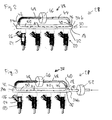
- FIGS. 2 and 3 show a fuel injection system 28 with the fuel rail 18 in detail.
- the fuel rail 18 comprises an inlet portion 30 which is arranged at a main tube 32 of the fuel rail 18.
- the main tube 32 has a longitudinal central axis A and a first axial end 34a and a second axial end 34b.
- the main tube 32 of the fuel rail 18 has a main tube cavity 36.
- the cross section of the main tube 32 can be of any shape, in particular of a circular or square shape.
- the main tube 32 is designed to contain fuel.
- the fuel injection system 28 has a fuel rail heating system 38.
- the fuel rail heating system 38 comprises the fuel rail 18, a pipe 40 and a heating device 48.
- the pipe 40 is hydraulically arranged between the two axial ends 34a, 34b of the fuel rail 18.
- the pipe 40 has an outer surface 42 and a pipe cavity 44.
- the pipe 40 and/or the main tube 32 are of a material comprising a metal.
- the pipe 40 and the fuel rail 18 are forming a common pipe-fuel-rail-circuit 50.
- the common pipe-fuel-rail-circuit 50 makes it possible that fuel can flow through the cavities 36, 44.
- a circulation pump 46 is hydraulically arranged in the pipe-fuel-rail-circuit 50.
- the circulation pump 46 can pump fuel through the both cavities 36, 44.
- the circulation pump 46 is hydraulically arranged in the pipe 40 thereby dividing the pipe 40 in two parts.
- the circulation pump 46 can be arranged hydraulically between the pipe 40 and the fuel rail 18.
- the heating device 48 is arranged at the outer surface 42 of the pipe 40. Consequently, the heating device 48 is thermally coupled to the pipe 40. In further embodiments, the heating device 48 is arranged at an outer surface of the main tube 32. In particular, if the pipe 40 and/or the main tube 32 are of a material comprising a metal, it is possible that the heat can flow with a high heat transfer rate from the heating device 48 to the fuel in the pipe cavity 44 and/or the main tube cavity 36. Consequently, the heating device 48 can heat up the fuel in the pipe-fuel-rail-circuit 50.
- the heating device 48 is arranged inside at least one of the main tube cavity 36 and pipe cavity 44. This enables that the heat can be transferred directly from the heating device 48 to the fuel in the pipe cavity 44 and/or the main tube cavity 36.
- FIG 3 shows a fuel injection system of a combustion engine 22 with a booster pump 52.
- the booster pump 52 is arranged hydraulically downstream the high pressure pump 15 and upstream the fuel rail 18. With the booster pump 52 a desired fuel pressure in the fuel rail 18 can be achieved. By this a good fuel spray is available from the fuel injector 20 due to a high pressure and a high temperature of the fuel. This is relevant in particular in view of fuels which comprise alcohols as ethanol in particular during the start period of the combustion engine 22.
- the fuel is heated up with the waste heat of the coil 24 of the injector 20 being coupled to the electrical supply, e.g. a battery, prior a cold start phase, the fuel being trapped inside the injector 20 can also be heated up very well.
- the electrical supply e.g. a battery
- Heating up the fuel with the described fuel rail heating system 38 comprises the described advantages in particular in view of fuels which include alcohols, e.g. ethanol, during cold start conditions of the combustion engine.
- fuels which include alcohols, e.g. ethanol
Landscapes
- Engineering & Computer Science (AREA)
- Chemical & Material Sciences (AREA)
- Combustion & Propulsion (AREA)
- Mechanical Engineering (AREA)
- General Engineering & Computer Science (AREA)
- Fuel-Injection Apparatus (AREA)
Abstract
Fuel rail heating system (38) of a combustion engine (22) comprising a fuel rail (18) with a main tube (32), the main tube (32) having a longitudinal central axis (A), two axial ends (34a, 34b) and a fuel rail cavity (36) being designed to contain fuel, a pipe (40) being hydraulically arranged between the two axial ends (34, 34a, 34b) of the fuel rail (18) and having a pipe cavity (44), the pipe (40) and the fuel rail (18) forming a common pipe-fuel-rail-circuit (50) to enable a common fuel circulation in the cavities (36, 44), and a heating device (48). The heating device (48) is thermally coupled to the main tube (32) and/or the pipe (40) and is designed to heat the fuel in the pipe-fuel-rail-circuit (50).
Description
- Fuel rail heating system of a combustion engine and Fuel injection system
- The invention relates to a fuel rail heating system of an internal combustion engine and a fuel injection system.
- Internal combustion engines with fuel injection systems are in widespread use. The fuel injection system can be designed to supply fuel to the internal combustion engine.
- In order to keep pressure fluctuations during the operation of the internal combustion engine at a very low level, internal combustion engines are supplied with a fuel accumulator to which fuel injectors are connected and which has a relatively large volume. Such a fuel accumulator is often referred to as a fuel rail. The fuel injection system includes the fuel rail and the fuel injector. Known fuel rails comprise a hollow body with recesses, wherein the fuel injectors are arranged.
-
WO 2006/130938 A1 discloses a fuel-heating assembly for an internal combustion engine, which comprises a fuel rail linked to a fuel entry which is connected to a fuel pressurization system, in the fuel rail a fuel outlet is present, which is in fluid communication with at least one injection valve, at least one heating element which is inserted in the fuel rail, and one heat transfer region in which the heating element is inserted. - The object of the invention is to create a fuel rail heating system which is simply to be manufactured and that enables a precise dosing of fuel.
- A further object of the invention is to create a fuel injection system of a combustion engine.
- The objects are achieved by the features of the independent claims. Advantageous embodiments of the invention are given in the sub-claims.
- According to a first aspect the invention is distinguished by a fuel rail heating system of a combustion engine comprising a fuel rail with a main tube, the main tube having a longitudinal central axis, two axial ends and a fuel rail cavity being designed to contain fuel, a pipe being hydraulically arranged between the two axial ends of the fuel rail and having a pipe cavity, the pipe and the fuel rail forming a common pipe-fuel-rail-circuit to enable a common fuel circulation in the cavities, and a heating device. The heating device is thermally coupled to the main tube and/or the pipe and is designed to heat the fuel in the pipe-fuel-rail-circuit.
- This has the advantage that a good heat transfer from the heating device to the fuel in the pipe cavity and the fuel rail cavity through the common pipe-fuel-rail-circuit is possible. In particular, a good movement of the fuel in the pipe-fuel-rail-circuit is possible. Consequently, a fast heating of the fuel in particular in the fuel rail is possible. This enables good cold start properties of the combustion engine in particular in view of fuels which comprise alcohols. Furthermore, only small variations in the construction compared to conventional fuel rails are necessary. Consequently, a low cost solution for the heating systems for fuel rails is possible.
- In an advantageous embodiment a circulation pump is hydraulically arranged in the pipe-fuel-rail-circuit. The circulation pump is designed to enable a forced common fuel circulation in the pipe cavity and the fuel rail cavity. This has the advantage that a high heat transfer rate from the heating device to the fuel in the cavities is possible.
- In a further advantageous embodiment the pipe has an outer surface and the heating device is arranged at the outer surface. This is a simple arrangement of the heating device at the pipes. In the case that the pipes are of a metal or comprise a metal a high heat transfer rate from the heating device to the fuel particular in the pipe cavity is possible. Furthermore, a large heat transfer surface between the heating device and the fuel is available.
- In a further advantageous embodiment the heating device is arranged in at least one of the cavities. This has the advantage that a high heat transfer rate from the heating device directly to the fuel is possible.
- According to a second aspect the invention is distinguished by a fuel injection system of a combustion engine comprising a fuel rail heating system according to the first aspect, a feed pump being designed to feed fuel out from a fuel tank, a high pressure pump being arranged hydraulically downstream the feed pump and being designed to pump fuel into a fuel rail of the fuel rail heating system, and at least one fuel injector being hydraulically coupled to the fuel rail. A booster pump is arranged hydraulically downstream the high pressure pump and hydraulically upstream the fuel rail. The booster pump is designed to obtain a desired fuel pressure in the fuel rail.
- This has the advantage that a good fuel spray is available from the injector due to a high pressure and a high temperature of the fuel, in particular in view of fuels which comprise alcohols and during cold start conditions of the combustion engine.
- Exemplary embodiments of the invention are explained in the following with the aid of schematic drawings. These are as follows:
-
Figure 1 an internal combustion engine with a fuel injection system in a schematic view, -
Figure 2 a first embodiment of a fuel rail heating system of the internal combustion engine in a schematic view, and -
Figure 3 a second embodiment of the fuel rail heating system in a schematic view. - Elements of the same design and function that occur in different illustrations are identified by the same reference character.
-
Figure 1 shows afuel feed device 10 which is assigned to aninternal combustion engine 22 of a vehicle. It includes afuel tank 12 that is connected via a fuel line to afuel feed pump 14. Ahigh pressure pump 15 is arranged hydraulically downstream the output of thefeed pump 14. The output of thehigh pressure pump 15 is hydraulically coupled to afuel inlet 16 of afuel rail 18. -
Fuel injectors 20 are coupled to thefuel rail 18. The fuel is fed to thefuel injectors 20 via thefuel rail 18. Thefuel injectors 20 have a sealed connection to thefuel rail 18. Thefuel injectors 20 are designed to be coupled to an electrical supply to actuate an actuator unit of thefuel injector 20. Preferably, the actuator unit comprises acoil 24 which is coupable to the electrical supply bypins 26 as can be seen inFigures 2 and 3 . -
Figures 2 and 3 show afuel injection system 28 with thefuel rail 18 in detail. - The
fuel rail 18 comprises aninlet portion 30 which is arranged at amain tube 32 of thefuel rail 18. Themain tube 32 has a longitudinal central axis A and a first axial end 34a and a secondaxial end 34b. - The
main tube 32 of thefuel rail 18 has amain tube cavity 36. The cross section of themain tube 32 can be of any shape, in particular of a circular or square shape. Themain tube 32 is designed to contain fuel. - The
fuel injection system 28 has a fuelrail heating system 38. The fuelrail heating system 38 comprises thefuel rail 18, apipe 40 and aheating device 48. - The
pipe 40 is hydraulically arranged between the twoaxial ends 34a, 34b of thefuel rail 18. Thepipe 40 has anouter surface 42 and apipe cavity 44. Preferably, thepipe 40 and/or themain tube 32 are of a material comprising a metal. - The
pipe 40 and thefuel rail 18 are forming a common pipe-fuel-rail-circuit 50. The common pipe-fuel-rail-circuit 50 makes it possible that fuel can flow through thecavities - A
circulation pump 46 is hydraulically arranged in the pipe-fuel-rail-circuit 50. Thecirculation pump 46 can pump fuel through the bothcavities Figures 2 and 3 thecirculation pump 46 is hydraulically arranged in thepipe 40 thereby dividing thepipe 40 in two parts. In further embodiments, thecirculation pump 46 can be arranged hydraulically between thepipe 40 and thefuel rail 18. - Preferably, the
heating device 48 is arranged at theouter surface 42 of thepipe 40. Consequently, theheating device 48 is thermally coupled to thepipe 40. In further embodiments, theheating device 48 is arranged at an outer surface of themain tube 32. In particular, if thepipe 40 and/or themain tube 32 are of a material comprising a metal, it is possible that the heat can flow with a high heat transfer rate from theheating device 48 to the fuel in thepipe cavity 44 and/or themain tube cavity 36. Consequently, theheating device 48 can heat up the fuel in the pipe-fuel-rail-circuit 50. - In further embodiments, the
heating device 48 is arranged inside at least one of themain tube cavity 36 andpipe cavity 44. This enables that the heat can be transferred directly from theheating device 48 to the fuel in thepipe cavity 44 and/or themain tube cavity 36. -
Figure 3 shows a fuel injection system of acombustion engine 22 with abooster pump 52. Thebooster pump 52 is arranged hydraulically downstream thehigh pressure pump 15 and upstream thefuel rail 18. With the booster pump 52 a desired fuel pressure in thefuel rail 18 can be achieved. By this a good fuel spray is available from thefuel injector 20 due to a high pressure and a high temperature of the fuel. This is relevant in particular in view of fuels which comprise alcohols as ethanol in particular during the start period of thecombustion engine 22. - In the following the function of the fuel
rail heating system 38 will be described in detail: - The fuel comes from the
inlet portion 30 and enters thefuel rail 18 at thesecond end 34b. Due to thehydraulic pump 46 the fuel is pumped through the pipe-fuel-rail-circuit 50 in a counterclockwise direction. Coming from thesecond end 34b of thefuel rail 18 the fuel enters thepipe 40. The heat of theheating device 48 being arranged at theouter surface 42 of thepipe 40 is transferred to the fuel in thepipe 40 and therefore, the fuel is heated up by theheating device 48. Due to the arrangement of the heating device 48 a fast heating of the fuel in thepipe 40 is possible. The heated fuel leaves thepipe 40 and enters thefuel rail 18 at the first end 34a. Depending on the fuel demand of theinjectors 20 the heated fuel can leave thefuel rail 18 through thefuel injectors 20 or is again passing thepipe 40 of the pipe-fuel-rail-circuit 50. - In the embodiment of
Figure 3 with thebooster pump 52 being arranged hydraulically downstream thehigh pressure pump 15 and upstream the fuel rail 18 a very high pressure is available in thefuel rail 18. Therefore and due to the high temperature of the fuel in thefuel rail 18 the fuel can be atomized in a very good manner and a well-distributed fuel spray in the combustion chamber of thecombustion engine 22 is available from thefuel injector 20. - Furthermore, if the fuel is heated up with the waste heat of the
coil 24 of theinjector 20 being coupled to the electrical supply, e.g. a battery, prior a cold start phase, the fuel being trapped inside theinjector 20 can also be heated up very well. - Heating up the fuel with the described fuel
rail heating system 38 comprises the described advantages in particular in view of fuels which include alcohols, e.g. ethanol, during cold start conditions of the combustion engine. - Although this invention is in particular described for
fuel rails 18 made of metal it can be applied tofuel rails 18 made of plastics as well.
Claims (5)
- Fuel rail heating system (38) of a combustion engine (22) comprising- a fuel rail (18) with a main tube (32), the main tube (32) having a longitudinal central axis (A), two axial ends (34a, 34b) and a fuel rail cavity (36) being designed to contain fuel,- a pipe (40) being hydraulically arranged between the two axial ends (34a, 34b) of the fuel rail (18) and having a pipe cavity (44), the pipe (40) and the fuel rail (18) forming a common pipe-fuel-rail-circuit (50) to enable a common fuel circulation in the cavities (36, 44), and- a heating device (48) being thermally coupled to the main tube (32) and/or the pipe (40) and being designed to heat the fuel in the pipe-fuel-rail-circuit (50).
- Fuel rail heating system (38) according to claim 1, wherein a circulation pump (46) is hydraulically arranged in the pipe-fuel-rail-circuit (50) and is designed to enable a forced common fuel circulation in the cavities (36, 44).
- Fuel rail heating system (38) according to claim 1 or 2, wherein the pipe (40) has an outer surface (42) and the heating device (48) is arranged at the outer surface (42).
- Fuel rail heating system (38) according to one of the preceding claims, wherein the heating device (48) is arranged in at least one of the cavities (36, 44).
- Fuel injection system (28) of a combustion engine (22) comprising- a fuel rail heating system (38) according to one of the preceding claims,- a feed pump (14) being designed to feed fuel out from a fuel tank (12),- a high pressure pump (15) being arranged hydraulically downstream the feed pump (14) and being designed to pump fuel into a fuel rail (18) of the fuel rail heating system (38), and- at least one fuel injector (20) being hydraulically coupled to the fuel rail (18),
wherein a booster pump (52) is arranged hydraulically downstream the high pressure pump (15) and hydraulically upstream the fuel rail (18) and is designed to obtain a desired fuel pressure in the fuel rail (18).
Priority Applications (1)
| Application Number | Priority Date | Filing Date | Title |
|---|---|---|---|
| EP09006191A EP2249023A1 (en) | 2009-05-06 | 2009-05-06 | Fuel rail heating system of a combustion engine and fuel injection system |
Applications Claiming Priority (1)
| Application Number | Priority Date | Filing Date | Title |
|---|---|---|---|
| EP09006191A EP2249023A1 (en) | 2009-05-06 | 2009-05-06 | Fuel rail heating system of a combustion engine and fuel injection system |
Publications (1)
| Publication Number | Publication Date |
|---|---|
| EP2249023A1 true EP2249023A1 (en) | 2010-11-10 |
Family
ID=41081121
Family Applications (1)
| Application Number | Title | Priority Date | Filing Date |
|---|---|---|---|
| EP09006191A Withdrawn EP2249023A1 (en) | 2009-05-06 | 2009-05-06 | Fuel rail heating system of a combustion engine and fuel injection system |
Country Status (1)
| Country | Link |
|---|---|
| EP (1) | EP2249023A1 (en) |
Citations (5)
| Publication number | Priority date | Publication date | Assignee | Title |
|---|---|---|---|---|
| GB2112458A (en) * | 1981-12-28 | 1983-07-20 | Ford Motor Co | Diesel engine heated fuel injection system |
| DE20113565U1 (en) * | 2001-08-16 | 2002-02-28 | Elsbett AG, 91177 Thalmässing | Injection device for a self-igniting engine operated with regenerative fuel |
| DE20113323U1 (en) * | 2001-08-20 | 2003-01-02 | Winkelmann, Karlheinrich, Dipl.-Ing. (TH), 33617 Bielefeld | Fuel preheater for internal combustion engines comprises a heat exchanger, through which the fuel of an internal combustion engine is pumped, heat exchanger being preheated by engine oil before being injected into the cylinder head |
| DE10140069A1 (en) * | 2001-08-16 | 2003-02-27 | Elsbett Ag | Independent heater for heating cold vegetable oil fuel before and/or while starting self-igniting common rail injection engine |
| WO2006130938A1 (en) | 2005-06-06 | 2006-12-14 | Robert Bosch Limitada | A fuel-heating assembly and method for the pre-heating of fuel of an internal combustion engine |
-
2009
- 2009-05-06 EP EP09006191A patent/EP2249023A1/en not_active Withdrawn
Patent Citations (5)
| Publication number | Priority date | Publication date | Assignee | Title |
|---|---|---|---|---|
| GB2112458A (en) * | 1981-12-28 | 1983-07-20 | Ford Motor Co | Diesel engine heated fuel injection system |
| DE20113565U1 (en) * | 2001-08-16 | 2002-02-28 | Elsbett AG, 91177 Thalmässing | Injection device for a self-igniting engine operated with regenerative fuel |
| DE10140069A1 (en) * | 2001-08-16 | 2003-02-27 | Elsbett Ag | Independent heater for heating cold vegetable oil fuel before and/or while starting self-igniting common rail injection engine |
| DE20113323U1 (en) * | 2001-08-20 | 2003-01-02 | Winkelmann, Karlheinrich, Dipl.-Ing. (TH), 33617 Bielefeld | Fuel preheater for internal combustion engines comprises a heat exchanger, through which the fuel of an internal combustion engine is pumped, heat exchanger being preheated by engine oil before being injected into the cylinder head |
| WO2006130938A1 (en) | 2005-06-06 | 2006-12-14 | Robert Bosch Limitada | A fuel-heating assembly and method for the pre-heating of fuel of an internal combustion engine |
Similar Documents
| Publication | Publication Date | Title |
|---|---|---|
| US7874282B2 (en) | Coupling device and fuel supply arrangement | |
| US6776140B2 (en) | Fuel supply installation in the form of a common-rail system of an internal combustion engine having a plurality of cylinders | |
| US20190085806A1 (en) | Valve For A High-Pressure Pump For A Motor Vehicle | |
| EP2093412B1 (en) | Coupling device | |
| EP2694797B1 (en) | Pump unit for supplying fuel, preferably diesel oil, from a containing tank to an internal combustion engine | |
| EP2652328B1 (en) | Pump unit for feeding fuel, preferably diesel fuel, from a storage tank to an internal combustion engine | |
| JP2010528205A (en) | Manufacturing and installation method of high pressure liquid LPG fuel supply device and dual or mixed fuel supply system | |
| WO2009009846A1 (en) | Fuel rail | |
| US9371824B2 (en) | Dosing device | |
| US9556843B2 (en) | Fuel injection nozzle | |
| EP2093413A1 (en) | Coupling device | |
| EP2375052B1 (en) | Fuel injector assembly | |
| US8302888B2 (en) | Fuel injector | |
| US20090301438A1 (en) | Fuel rail of a combustion engine | |
| JP2016520764A (en) | Fuel piping configuration of common rail fuel supply system | |
| EP2372140B1 (en) | Coupling device | |
| EP2249023A1 (en) | Fuel rail heating system of a combustion engine and fuel injection system | |
| EP1612406B1 (en) | An injection system for an internal combustion engine | |
| CN101688503A (en) | Fuel injectors with runner inserts | |
| US8069841B2 (en) | Coupling arrangement and fuel injector | |
| EP2385241B1 (en) | Pulsation damper | |
| CN102713238B (en) | Injection valves for fluids | |
| CN106870164A (en) | A kind of aero-engine fuel regulator | |
| JP5263135B2 (en) | Fuel injection valve | |
| EP2204573A1 (en) | Fuel supply system |
Legal Events
| Date | Code | Title | Description |
|---|---|---|---|
| PUAI | Public reference made under article 153(3) epc to a published international application that has entered the european phase |
Free format text: ORIGINAL CODE: 0009012 |
|
| AK | Designated contracting states |
Kind code of ref document: A1 Designated state(s): AT BE BG CH CY CZ DE DK EE ES FI FR GB GR HR HU IE IS IT LI LT LU LV MC MK MT NL NO PL PT RO SE SI SK TR |
|
| AX | Request for extension of the european patent |
Extension state: AL BA RS |
|
| 17P | Request for examination filed |
Effective date: 20110510 |
|
| 17Q | First examination report despatched |
Effective date: 20110525 |
|
| D17P | Request for examination filed (deleted) | ||
| STAA | Information on the status of an ep patent application or granted ep patent |
Free format text: STATUS: THE APPLICATION IS DEEMED TO BE WITHDRAWN |
|
| 18D | Application deemed to be withdrawn |
Effective date: 20110510 |