EP2248408B2 - Lifting mechanism - Google Patents
Lifting mechanism Download PDFInfo
- Publication number
- EP2248408B2 EP2248408B2 EP10004424.7A EP10004424A EP2248408B2 EP 2248408 B2 EP2248408 B2 EP 2248408B2 EP 10004424 A EP10004424 A EP 10004424A EP 2248408 B2 EP2248408 B2 EP 2248408B2
- Authority
- EP
- European Patent Office
- Prior art keywords
- arm
- valve
- lifting mechanism
- mechanism according
- operational condition
- Prior art date
- Legal status (The legal status is an assumption and is not a legal conclusion. Google has not performed a legal analysis and makes no representation as to the accuracy of the status listed.)
- Active
Links
Images


Classifications
-
- A—HUMAN NECESSITIES
- A01—AGRICULTURE; FORESTRY; ANIMAL HUSBANDRY; HUNTING; TRAPPING; FISHING
- A01B—SOIL WORKING IN AGRICULTURE OR FORESTRY; PARTS, DETAILS, OR ACCESSORIES OF AGRICULTURAL MACHINES OR IMPLEMENTS, IN GENERAL
- A01B63/00—Lifting or adjusting devices or arrangements for agricultural machines or implements
- A01B63/02—Lifting or adjusting devices or arrangements for agricultural machines or implements for implements mounted on tractors
- A01B63/10—Lifting or adjusting devices or arrangements for agricultural machines or implements for implements mounted on tractors operated by hydraulic or pneumatic means
-
- A—HUMAN NECESSITIES
- A01—AGRICULTURE; FORESTRY; ANIMAL HUSBANDRY; HUNTING; TRAPPING; FISHING
- A01B—SOIL WORKING IN AGRICULTURE OR FORESTRY; PARTS, DETAILS, OR ACCESSORIES OF AGRICULTURAL MACHINES OR IMPLEMENTS, IN GENERAL
- A01B63/00—Lifting or adjusting devices or arrangements for agricultural machines or implements
- A01B63/14—Lifting or adjusting devices or arrangements for agricultural machines or implements for implements drawn by animals or tractors
- A01B63/24—Tools or tool-holders adjustable relatively to the frame
- A01B63/32—Tools or tool-holders adjustable relatively to the frame operated by hydraulic or pneumatic means without automatic control
-
- A—HUMAN NECESSITIES
- A01—AGRICULTURE; FORESTRY; ANIMAL HUSBANDRY; HUNTING; TRAPPING; FISHING
- A01D—HARVESTING; MOWING
- A01D34/00—Mowers; Mowing apparatus of harvesters
- A01D34/01—Mowers; Mowing apparatus of harvesters characterised by features relating to the type of cutting apparatus
- A01D34/02—Mowers; Mowing apparatus of harvesters characterised by features relating to the type of cutting apparatus having reciprocating cutters
- A01D34/24—Lifting devices for the cutter-bar
- A01D34/246—Hydraulic lifting devices
-
- A—HUMAN NECESSITIES
- A01—AGRICULTURE; FORESTRY; ANIMAL HUSBANDRY; HUNTING; TRAPPING; FISHING
- A01D—HARVESTING; MOWING
- A01D34/00—Mowers; Mowing apparatus of harvesters
- A01D34/01—Mowers; Mowing apparatus of harvesters characterised by features relating to the type of cutting apparatus
- A01D34/412—Mowers; Mowing apparatus of harvesters characterised by features relating to the type of cutting apparatus having rotating cutters
- A01D34/63—Mowers; Mowing apparatus of harvesters characterised by features relating to the type of cutting apparatus having rotating cutters having cutters rotating about a vertical axis
- A01D34/64—Mowers; Mowing apparatus of harvesters characterised by features relating to the type of cutting apparatus having rotating cutters having cutters rotating about a vertical axis mounted on a vehicle, e.g. a tractor, or drawn by an animal or a vehicle
- A01D34/66—Mowers; Mowing apparatus of harvesters characterised by features relating to the type of cutting apparatus having rotating cutters having cutters rotating about a vertical axis mounted on a vehicle, e.g. a tractor, or drawn by an animal or a vehicle with two or more cutters
- A01D34/661—Mounting means
Definitions
- the present invention relates to a lifting mechanism and in particular, but not exclusively, to a lifting mechanism for a mower, such as an agricultural mower.
- an agricultural mower comprising a cutter unit having a number of rotating cutter discs, a support arm for supporting the cutter unit and a mounting structure for mounting the mower on a tractor.
- the support arm is attached to the mounting structure through a pivot that allows the position of the cutter unit to be adjusted.
- the cutter unit may for example be adjusted to a cutting position in which it engages the ground, a headland position in which the cutter unit is slightly raised from the ground to allow the tractor to turn when it reaches the headland (the edge of a field), and a transport position in which the cutter unit is folded behind the tractor.
- the cutter unit When the cutter unit is in the cutting position, it usually extends outwards to one side of the tractor: lifting the cutter unit to the transport position allows the tractor to drive down a public road without the cutter unit extending outwards beyond the tractor.
- a hydraulic cylinder is usually provided to lift the cutter unit from the cutting position to the headland position or the transport position.
- a support spring is also usually provided, which carries part of the weight of the cutter unit when it is in the cutting position. This allows the cutter unit to rest lightly on the ground (for example with a force of about 100kgs) and follow the contours of the ground during a mowing operation.
- the stop can be displaced (for example with a control cord) to allow the cutter unit to be lifted past the stop to the transport position.
- the arm is pressed against the stop with the full force of the hydraulic system. We have found that this places very high loads on the mechanism, which in time can cause components of the mechanism to fail.
- EP0839443 discloses a cutting machine fitted with an automatic retractable stop.
- the actuator is arranged to close the valve as the arm reaches the second position, thereby preventing further movement of the arm.
- a mechanical stop is not required and therefore the large stresses encountered in earlier mechanisms that use a mechanical stop are avoided. This makes the mechanism more reliable and less likely to fail.
- operation of the actuator and the valve is designed to ensure that when the pressure of the hydraulic drive fluid is reversed, the arm returns to the first position.
- the lifting mechanism may be designed for use with an agricultural mower or any other suitable apparatus.
- the second arm position is a headland position.
- the arm is arranged for movement to a third position, which is a raised, non-working position.
- the third position is a transport position. In the case of a mower, this allows the cutter unit to be folded behind the tractor, allowing it to be driven down a public road.
- the lifting mechanism includes a control means that is operable to allow movement of the arm beyond the second position to the third position.
- the control means thus over-rides normal operation of the valve, which prevents further movement when the arm reaches the second position.
- the control means is constructed and arranged to move the valve to a third operational condition in which flow is permitted.
- the valve is arranged such that when it is in the third operational condition, the flow of hydraulic fluid is permitted at a reduced flow rate, as compared to the flow rate when the valve is in the first operational condition, and hydraulic fluid is directed through a flow restrictor. This ensures that movement of the arm to the third position takes place at a relatively slow speed, to avoid placing excessive mechanical stresses on the mechanism.
- the lifting mechanism may be designed for use with an agricultural mower or any other suitable apparatus, in which the first position is a working position and the second position is a raised non-working position.
- the arm is arranged to pivot about a substantially horizontal pivot axis.
- the third position is a transport position. In the case of a mower, this allows the cutter unit to be folded behind the tractor, allowing it to be driven down a public road.
- the second position is a headland position. For a mower this allows the cutter unit to be raised slightly above the ground, allowing the tractor to make a sharp turn.
- control means comprises a manual control, for example a control cord operable from the cab of a tractor, which moves the valve to the third operational condition.
- control means may comprise an electrical control, for example a control switch operable from the cab of a tractor, which operates an actuator to move the valve to the third operational condition
- the actuator is constructed and arranged to hold the valve in the second condition if operation of the control means ceases while the arm is between the second and third positions.
- This provides a safety feature, which ensures that movement of the arm to and from the third position cannot take place accidentally, for example if the hydraulic controls are inadvertently actuated.
- the control means is released during movement of the arm between the second and third positions, movement of the arm will immediately cease.
- the hydraulic drive means includes a lost motion mechanism that permits limited pivoting movement of the arm in the first position. In the case of a mower, this allows the cutter unit to follow the contours of the ground during a mowing operation.
- the hydraulic drive means is constructed and arranged to act between the mounting structure and the arm.
- the lifting mechanism includes a support element for supporting the arm in the first position.
- the support element comprises a spring.
- the support mechanism carries some of the weight of the arm and any mechanism carried by the arm. In the case of a mower, this ensures that the cutter unit rests relatively lightly on the ground, to avoid excessive drag.
- a mower including a lifting mechanism according to any one of the preceding statements of invention, and a cutter unit attached to and supported by the arm.
- the support structure is arranged for attachment to, or is attached to, a tractor.
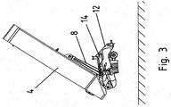
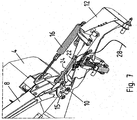
- the lifting mechanism 2 is attached to a conventional cutter unit 4, which may for example be similar to that described in WO99/18769A .
- the cutter unit 4 includes a housing that contains a number of rotating cutter discs (not shown). It may optionally also include a conditioner unit (not shown).
- the cutter unit 4 is attached through a pivot 6 to a support arm 8. The pivot 6 allows the cutter unit 4 to rock so that it can follow the contours of the ground during a mowing operation.
- the arm 8 is attached through a pivot 10 to a mounting structure 12, which in use is mounted on a tractor (not shown).
- a tractor not shown
- the mower unit is mounted on the rear of a tractor, although it can alternatively be mounted on the front or side of a tractor.
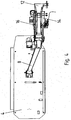
- the pivot 10 allows the arm 8 to be lifted from the working position shown in Figures 1 , 4 and 6 to a headland position shown in Figures 2 , 5 and 7 or a transport position shown in Figures 3 and 8 .
- the cutter unit 4 engages the ground so that the rotating cutters sever the standing crops close to ground level.
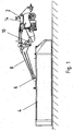
- the lifting mechanism includes a hydraulic cylinder 14 that is attached at a first end 14a to a pivot on the mounting structure 12.
- the second end 14b of the hydraulic cylinder 14 is attached to an actuating lever 15, which is attached to a pivot point 8a on the arm.
- a stop 8b is provided on the arm, for engagement with the lever 15 when the arm is lifted.
- the hydraulic cylinder 14 can be actuated to lift the cutter unit 4 from the working position to the headland position or the transport position. By reversing the flow of fluid through the hydraulic system, the cutter unit 4 can be returned to the working position.
- the lifting mechanism also includes a strong coil spring 16, one end of which is attached to the support structure 12, the other end being attached through an adjustable chain 18 to the arm 8.
- the spring 16 When the mower is in the working position, the spring 16 is in tension and partially supports the weight of the cutter unit 4, so that the cutter unit rests only lightly against the ground. This allows the cutter unit to follow the contours of the ground during mowing.
- a gap is provided between the lever 15 and the stop 8b. This gap provides a lost motion mechanism in the connection between the hydraulic cylinder 14 and the arm 8 to allow for movement of the arm 8 during mowing.
- the hydraulic cylinder 14 is connected to a hydraulic system that includes a control valve 20 having a control lever 22.
- the valve 20 controls the flow of hydraulic fluid to and from the cylinder 14, as will be described in more detail below.
- the valve 20 is operated by an actuator rod 24 that is attached to the second end 14b of the piston rod.
- the actuator rod 24 is withdrawn from contact with the lever 22, which is held in an anticlockwise-rotated direction by a biasing spring 26. This places the valve in a first operative condition, illustrated in Figure 9 .
- a control cord 28 is attached to the lever 22. This cord 28 extends to a position where it can be reached by an operator, for example within the cab of the tractor. Pulling the cord 28 allows the operator to rotate the valve lever 22 clockwise, thus overriding the biasing spring 26 and the actuator rod 24.
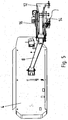
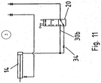
- valve lever 22 In order to lift the arm 8 to the transport position shown in Figure 8 , the valve lever 22 must be rotated further in a clockwise direction to place the valve in a third operational condition as illustrated in Figure 11 . This is achieved by pulling the control cord 28, as shown in Figure 8 . If the control cord 28 is subsequently released, the valve lever 22 will rotate anticlockwise under action of the spring 26 until it contacts the actuator rod 24, thus returning the valve 20 to the second operational condition.
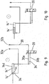
- the hydraulic circuit of the lifting mechanism is shown in Figures 9 to 11 .
- the circuit includes the hydraulic cylinder 14, the valve 20, a number of fluid flow lines 30 and two connectors 32a, 32b for connecting the hydraulic circuit to the hydraulic drive system of a tractor (not shown).
- a number of flow restriction valves 34 are provided in certain of the fluid flow lines 30.
- the hydraulic cylinder 14 is conventional and comprises a piston 14c and a cylinder barrel 14d, wherein the piston 14c divides the internal volume of the cylinder barrel 14d into a left hand chamber 14' and a right hand chamber 14".
- the left hand chamber 14' is connected directly to the first connector 32a and the right hand chamber 14" is connected via the valve 20 to the second connector 32b.
- the valve 20 has three operational conditions.
- the valve is shown in the first operational condition, in which hydraulic fluid can flow to and from the right hand chamber 14" of the hydraulic cylinder 14 through a first unrestricted flow line 30a.
- the valve is shown in the second operational condition in which the valve is closed, preventing any flow of fluid to or from the right hand chamber 14".
- the valve is shown in the third operational condition, in which hydraulic fluid can flow to and from right hand chamber 14" through a second flow line 30b that includes a flow restriction valve 34.
- the cutter unit 4 is placed in the working position shown in Figures 1 , 4 and 6 .
- the valve 20 is in the first operating condition illustrated in Figure 9 , which permits unrestricted flow of hydraulic fluid to and from the hydraulic cylinder 14. This allows the cutter unit to be raised or lowered by adjusting the pressure in the left hand chamber 14' of the hydraulic cylinder through the first connector 32a. The fluid displaced from the right hand chamber 14" flows to and from an unpressurised reservoir through the second connector 32b.
- the hydraulic drive system is usually set to extend the piston 14c fully, as shown in Figure 9 . In this position, owing to the provision of a lost motion mechanism between the piston rod and the arm 8, the hydraulic cylinder does not exert any force on the arm. The arm can therefore rotate to a limited degree about the arm pivot 10.
- the weight of the cutter unit 4 is supported partially by the spring 16, so that the cutter unit rests lightly on the ground.
- the hydraulic cylinder 14 When the tractor reaches a headland, the hydraulic cylinder 14 is operated to lift the cutter unit 4 to the headland position shown in Figures 2 , 5 and 7 . Fluid is supplied under pressure to the left hand chamber 14' from the first connector 32a, forcing the piston 14c to the right and lifting the arm 8. As the arm 8 nears the headland position, the actuator rod 24 engages the valve lever 22 and rotates it clockwise against the bias of the spring 26. This moves the valve 20 towards the second operational condition shown in Figure 10 .
- the actuator rod 24 is set so that when the arm 8 reaches the headland position, the valve 20 closes to prevent fluid escaping from the right hand chamber 14", thereby preventing further movement of the arm 8. This locks the arm in the headland position.
- the pressure supplied to the left hand chamber 14' is reduced.
- the weight of the arm 8 and the cutter unit 4 is then sufficient to pull the piston 14c to the left, forcing fluid back through the first connector 32a and creating a partial vacuum in the right hand chamber 14".
- the actuator rod 24 disengages the valve 20, allowing it to return to the first operational condition shown in Figure 9 . This allows the cutter unit 4 to be lowered again to the working position.
- the control cord 28 in order to raise the arm 8 to the transport position, the control cord 28 must be operated to move the valve 20 to the third operational condition as shown in Figure 11 .
- This allows hydraulic fluid to flow to and from the hydraulic cylinder 14 through the restrictor valve 34 in the second flow line 30b.
- the restrictor valve 34 limits the flow rate of hydraulic fluid, ensuring that movement of the arm 8 between the headland position and the transport position is relatively slow. This in turn ensures that the stresses induced in the mechanism by operation of the lifting mechanism are greatly reduced, thereby reducing the risk of mechanical failure.
- valve 20 will return to the second operational condition shown in Figure 10 under the bias of the spring 26. This cuts off the flow of hydraulic fluid, preventing further movement of the arm. The arm cannot then be moved until the control cord 28 is pulled again, to move the valve 20 to the third operational condition. This acts as a safety feature ensuring that the mower cannot be lowered accidentally by inadvertently activating the tractor hydraulics. The mower will only move from the transport position if the control cord 28 is pulled and the tractor hydraulics are operated at the same time.
- valve control cord 28 may be replaced by an electrical control, for example a switch operable from the cab that operates the valve via an electrical actuator.
Landscapes
- Life Sciences & Earth Sciences (AREA)
- Environmental Sciences (AREA)
- Engineering & Computer Science (AREA)
- Mechanical Engineering (AREA)
- Soil Sciences (AREA)
- Zoology (AREA)
- Lifting Devices For Agricultural Implements (AREA)
- Harvester Elements (AREA)
Priority Applications (1)
| Application Number | Priority Date | Filing Date | Title |
|---|---|---|---|
| PL10004424T PL2248408T5 (pl) | 2009-04-29 | 2010-04-27 | Mechanizm podnoszący |
Applications Claiming Priority (1)
| Application Number | Priority Date | Filing Date | Title |
|---|---|---|---|
| GB0907357.8A GB2469836B (en) | 2009-04-29 | 2009-04-29 | Lifting mechanism |
Publications (4)
| Publication Number | Publication Date |
|---|---|
| EP2248408A2 EP2248408A2 (en) | 2010-11-10 |
| EP2248408A3 EP2248408A3 (en) | 2013-12-04 |
| EP2248408B1 EP2248408B1 (en) | 2015-02-11 |
| EP2248408B2 true EP2248408B2 (en) | 2019-04-03 |
Family
ID=40791983
Family Applications (1)
| Application Number | Title | Priority Date | Filing Date |
|---|---|---|---|
| EP10004424.7A Active EP2248408B2 (en) | 2009-04-29 | 2010-04-27 | Lifting mechanism |
Country Status (4)
| Country | Link |
|---|---|
| EP (1) | EP2248408B2 (pl) |
| DK (1) | DK2248408T4 (pl) |
| GB (1) | GB2469836B (pl) |
| PL (1) | PL2248408T5 (pl) |
Families Citing this family (4)
| Publication number | Priority date | Publication date | Assignee | Title |
|---|---|---|---|---|
| FR2993136B1 (fr) * | 2012-07-12 | 2015-04-10 | Kuhn Sa | Machine de coupe comportant un dispositif de deplacement perfectionne |
| DE102014104379A1 (de) * | 2014-03-28 | 2015-10-01 | Claas Saulgau Gmbh | Arbeitsgerät zum Ankuppeln an eine landwirtschaftliche Arbeitsmaschine |
| US11297765B2 (en) | 2018-07-02 | 2022-04-12 | Deere & Company | Suspension compliance to reduce frame loading |
| US10820511B2 (en) | 2018-07-05 | 2020-11-03 | Deere & Company | Wing locking with hydraulic blocker valve |
Citations (8)
| Publication number | Priority date | Publication date | Assignee | Title |
|---|---|---|---|---|
| US2755776A (en) † | 1955-05-10 | 1956-07-24 | Leroy A Morris | Stroke control for hydraulic cylinder |
| GB1019398A (en) † | 1962-07-16 | 1966-02-09 | Int Harvester Co | Hydraulic system for farm tractors |
| GB2145912A (en) † | 1983-07-19 | 1985-04-11 | Amazonen Werke Dreyer H | An agricultural apparatus comprising a combination of agricultural implements |
| EP0839443A1 (fr) † | 1996-10-31 | 1998-05-06 | Kuhn S.A. | Machine de coupe |
| EP1050205A1 (de) † | 1999-05-05 | 2000-11-08 | Claas Saulgau Gmbh | Heuwerbungsmaschine |
| EP1209365A2 (en) † | 2000-11-27 | 2002-05-29 | Lely Enterprises AG | A method of controlling a control cylinder, as well as an agricultural machine for applying said method |
| DE20219242U1 (de) † | 2002-12-12 | 2003-02-20 | Wilhelm Stoll Maschinenfabrik Gmbh, 38268 Lengede | Heuwerbungsmaschine |
| NL1020593C2 (nl) † | 2002-05-14 | 2003-11-17 | Lely Entpr Ag | Werkwijze voor het aansturen van een bedieningscilinder, een landbouwmachine waarin deze werkwijze wordt toegepast, alsmede inrichting voor het bedienen van een bedieningscilinder. |
Family Cites Families (7)
| Publication number | Priority date | Publication date | Assignee | Title |
|---|---|---|---|---|
| GB1014969A (en) * | 1963-11-23 | 1965-12-31 | Harrison Mcgregor And Guest Lt | An improvement in or relating to mowing machines |
| US4048789A (en) * | 1976-07-09 | 1977-09-20 | Cartner Jack O | Mower attachment for tractors |
| EP0734645A3 (en) * | 1995-03-01 | 1996-11-20 | Freudendahl J Fab As | Hanging agricultural implement |
| GB9721311D0 (en) | 1997-10-09 | 1997-12-10 | Kverneland Taarup As | Multi-disc mowing machine |
| FR2794934B1 (fr) * | 1999-06-17 | 2001-08-10 | Kuhn Sa | Machine agricole du type faucheuse ou faucheuse- conditionnneuse comportant un organe d'amortissement |
| DE20109019U1 (de) * | 2001-05-30 | 2001-08-16 | Gebr. Pöttinger GmbH, 86899 Landsberg | Mähwerk |
| DE20316727U1 (de) * | 2003-10-30 | 2004-01-08 | Fella-Werke Gmbh & Co. Kg | Hebekinematik |
-
2009
- 2009-04-29 GB GB0907357.8A patent/GB2469836B/en active Active
-
2010
- 2010-04-27 EP EP10004424.7A patent/EP2248408B2/en active Active
- 2010-04-27 DK DK10004424.7T patent/DK2248408T4/da active
- 2010-04-27 PL PL10004424T patent/PL2248408T5/pl unknown
Patent Citations (8)
| Publication number | Priority date | Publication date | Assignee | Title |
|---|---|---|---|---|
| US2755776A (en) † | 1955-05-10 | 1956-07-24 | Leroy A Morris | Stroke control for hydraulic cylinder |
| GB1019398A (en) † | 1962-07-16 | 1966-02-09 | Int Harvester Co | Hydraulic system for farm tractors |
| GB2145912A (en) † | 1983-07-19 | 1985-04-11 | Amazonen Werke Dreyer H | An agricultural apparatus comprising a combination of agricultural implements |
| EP0839443A1 (fr) † | 1996-10-31 | 1998-05-06 | Kuhn S.A. | Machine de coupe |
| EP1050205A1 (de) † | 1999-05-05 | 2000-11-08 | Claas Saulgau Gmbh | Heuwerbungsmaschine |
| EP1209365A2 (en) † | 2000-11-27 | 2002-05-29 | Lely Enterprises AG | A method of controlling a control cylinder, as well as an agricultural machine for applying said method |
| NL1020593C2 (nl) † | 2002-05-14 | 2003-11-17 | Lely Entpr Ag | Werkwijze voor het aansturen van een bedieningscilinder, een landbouwmachine waarin deze werkwijze wordt toegepast, alsmede inrichting voor het bedienen van een bedieningscilinder. |
| DE20219242U1 (de) † | 2002-12-12 | 2003-02-20 | Wilhelm Stoll Maschinenfabrik Gmbh, 38268 Lengede | Heuwerbungsmaschine |
Also Published As
| Publication number | Publication date |
|---|---|
| GB2469836A (en) | 2010-11-03 |
| EP2248408A2 (en) | 2010-11-10 |
| GB0907357D0 (en) | 2009-06-10 |
| PL2248408T5 (pl) | 2019-07-31 |
| DK2248408T3 (en) | 2015-03-09 |
| PL2248408T3 (pl) | 2015-09-30 |
| EP2248408B1 (en) | 2015-02-11 |
| DK2248408T4 (da) | 2019-05-13 |
| EP2248408A3 (en) | 2013-12-04 |
| GB2469836B (en) | 2012-10-17 |
Similar Documents
| Publication | Publication Date | Title |
|---|---|---|
| US7730705B2 (en) | Electro-hydraulic lift mechanism for lawn mower deck | |
| EP2656716B1 (en) | Pull-type crop harvesting machine transport system where the machine remains balanced on transport wheels and the hitch as the transport system is deployed | |
| US7716906B2 (en) | Single lever mower deck height-of-cut control | |
| US10655302B2 (en) | Valve assembly for work attachment | |
| EP2248408B2 (en) | Lifting mechanism | |
| US6431231B1 (en) | Hydraulically controlled stump grinder | |
| EP2654395B1 (en) | Hydraulic arrangement for a lifting unit | |
| US20080141640A1 (en) | Flip up arrangement for a mower deck | |
| EP0941647B1 (en) | Four bar linkage mounting for mowers | |
| US5822960A (en) | Reel mower | |
| JP6598292B2 (ja) | 草刈機 | |
| US3417555A (en) | Automatic table height control | |
| US7340877B2 (en) | Cutter unit support roller | |
| JPS608648Y2 (ja) | 昇降装置 | |
| US20250212715A1 (en) | Transport hydraulic pressure used to block retraction of header tilt cylinder | |
| CA1318508C (en) | Single lever control for selectively effecting lifting of multiple cutting units of a mower | |
| JPH0541621Y2 (pl) | ||
| JPH0115289Y2 (pl) | ||
| JP2502554Y2 (ja) | コンバインにおける後刈刃の昇降装置 | |
| JP4232271B2 (ja) | 農作業機 | |
| US20050193702A1 (en) | Brush cutter emergency stop system | |
| JPH0333211Y2 (pl) | ||
| JPS5820089Y2 (ja) | 刈取収穫機の操作装置 | |
| JPS6131623Y2 (pl) | ||
| JPH0525386Y2 (pl) |
Legal Events
| Date | Code | Title | Description |
|---|---|---|---|
| PUAI | Public reference made under article 153(3) epc to a published international application that has entered the european phase |
Free format text: ORIGINAL CODE: 0009012 |
|
| AK | Designated contracting states |
Kind code of ref document: A2 Designated state(s): AT BE BG CH CY CZ DE DK EE ES FI FR GB GR HR HU IE IS IT LI LT LU LV MC MK MT NL NO PL PT RO SE SI SK SM TR |
|
| AX | Request for extension of the european patent |
Extension state: AL BA ME RS |
|
| PUAL | Search report despatched |
Free format text: ORIGINAL CODE: 0009013 |
|
| AK | Designated contracting states |
Kind code of ref document: A3 Designated state(s): AT BE BG CH CY CZ DE DK EE ES FI FR GB GR HR HU IE IS IT LI LT LU LV MC MK MT NL NO PL PT RO SE SI SK SM TR |
|
| AX | Request for extension of the european patent |
Extension state: AL BA ME RS |
|
| RIC1 | Information provided on ipc code assigned before grant |
Ipc: A01B 63/10 20060101ALI20131028BHEP Ipc: A01D 34/66 20060101AFI20131028BHEP |
|
| 17P | Request for examination filed |
Effective date: 20131220 |
|
| RBV | Designated contracting states (corrected) |
Designated state(s): AT BE BG CH CY CZ DE DK EE ES FI FR GB GR HR HU IE IS IT LI LT LU LV MC MK MT NL NO PL PT RO SE SI SK SM TR |
|
| GRAP | Despatch of communication of intention to grant a patent |
Free format text: ORIGINAL CODE: EPIDOSNIGR1 |
|
| INTG | Intention to grant announced |
Effective date: 20141029 |
|
| GRAS | Grant fee paid |
Free format text: ORIGINAL CODE: EPIDOSNIGR3 |
|
| GRAA | (expected) grant |
Free format text: ORIGINAL CODE: 0009210 |
|
| AK | Designated contracting states |
Kind code of ref document: B1 Designated state(s): AT BE BG CH CY CZ DE DK EE ES FI FR GB GR HR HU IE IS IT LI LT LU LV MC MK MT NL NO PL PT RO SE SI SK SM TR |
|
| REG | Reference to a national code |
Ref country code: GB Ref legal event code: FG4D |
|
| REG | Reference to a national code |
Ref country code: CH Ref legal event code: EP |
|
| REG | Reference to a national code |
Ref country code: DK Ref legal event code: T3 Effective date: 20150305 |
|
| REG | Reference to a national code |
Ref country code: NL Ref legal event code: T3 Ref country code: IE Ref legal event code: FG4D |
|
| REG | Reference to a national code |
Ref country code: AT Ref legal event code: REF Ref document number: 709631 Country of ref document: AT Kind code of ref document: T Effective date: 20150315 |
|
| REG | Reference to a national code |
Ref country code: DE Ref legal event code: R096 Ref document number: 602010022177 Country of ref document: DE Effective date: 20150326 |
|
| REG | Reference to a national code |
Ref country code: FR Ref legal event code: PLFP Year of fee payment: 6 |
|
| REG | Reference to a national code |
Ref country code: LT Ref legal event code: MG4D |
|
| PG25 | Lapsed in a contracting state [announced via postgrant information from national office to epo] |
Ref country code: ES Free format text: LAPSE BECAUSE OF FAILURE TO SUBMIT A TRANSLATION OF THE DESCRIPTION OR TO PAY THE FEE WITHIN THE PRESCRIBED TIME-LIMIT Effective date: 20150211 Ref country code: NO Free format text: LAPSE BECAUSE OF FAILURE TO SUBMIT A TRANSLATION OF THE DESCRIPTION OR TO PAY THE FEE WITHIN THE PRESCRIBED TIME-LIMIT Effective date: 20150511 Ref country code: HR Free format text: LAPSE BECAUSE OF FAILURE TO SUBMIT A TRANSLATION OF THE DESCRIPTION OR TO PAY THE FEE WITHIN THE PRESCRIBED TIME-LIMIT Effective date: 20150211 Ref country code: LT Free format text: LAPSE BECAUSE OF FAILURE TO SUBMIT A TRANSLATION OF THE DESCRIPTION OR TO PAY THE FEE WITHIN THE PRESCRIBED TIME-LIMIT Effective date: 20150211 Ref country code: SE Free format text: LAPSE BECAUSE OF FAILURE TO SUBMIT A TRANSLATION OF THE DESCRIPTION OR TO PAY THE FEE WITHIN THE PRESCRIBED TIME-LIMIT Effective date: 20150211 |
|
| PG25 | Lapsed in a contracting state [announced via postgrant information from national office to epo] |
Ref country code: IS Free format text: LAPSE BECAUSE OF FAILURE TO SUBMIT A TRANSLATION OF THE DESCRIPTION OR TO PAY THE FEE WITHIN THE PRESCRIBED TIME-LIMIT Effective date: 20150611 Ref country code: LV Free format text: LAPSE BECAUSE OF FAILURE TO SUBMIT A TRANSLATION OF THE DESCRIPTION OR TO PAY THE FEE WITHIN THE PRESCRIBED TIME-LIMIT Effective date: 20150211 Ref country code: GR Free format text: LAPSE BECAUSE OF FAILURE TO SUBMIT A TRANSLATION OF THE DESCRIPTION OR TO PAY THE FEE WITHIN THE PRESCRIBED TIME-LIMIT Effective date: 20150512 |
|
| REG | Reference to a national code |
Ref country code: PL Ref legal event code: T3 |
|
| PG25 | Lapsed in a contracting state [announced via postgrant information from national office to epo] |
Ref country code: SK Free format text: LAPSE BECAUSE OF FAILURE TO SUBMIT A TRANSLATION OF THE DESCRIPTION OR TO PAY THE FEE WITHIN THE PRESCRIBED TIME-LIMIT Effective date: 20150211 Ref country code: RO Free format text: LAPSE BECAUSE OF FAILURE TO SUBMIT A TRANSLATION OF THE DESCRIPTION OR TO PAY THE FEE WITHIN THE PRESCRIBED TIME-LIMIT Effective date: 20150211 Ref country code: EE Free format text: LAPSE BECAUSE OF FAILURE TO SUBMIT A TRANSLATION OF THE DESCRIPTION OR TO PAY THE FEE WITHIN THE PRESCRIBED TIME-LIMIT Effective date: 20150211 |
|
| REG | Reference to a national code |
Ref country code: DE Ref legal event code: R026 Ref document number: 602010022177 Country of ref document: DE |
|
| PLBI | Opposition filed |
Free format text: ORIGINAL CODE: 0009260 |
|
| PG25 | Lapsed in a contracting state [announced via postgrant information from national office to epo] |
Ref country code: LU Free format text: LAPSE BECAUSE OF FAILURE TO SUBMIT A TRANSLATION OF THE DESCRIPTION OR TO PAY THE FEE WITHIN THE PRESCRIBED TIME-LIMIT Effective date: 20150427 Ref country code: MC Free format text: LAPSE BECAUSE OF FAILURE TO SUBMIT A TRANSLATION OF THE DESCRIPTION OR TO PAY THE FEE WITHIN THE PRESCRIBED TIME-LIMIT Effective date: 20150211 |
|
| REG | Reference to a national code |
Ref country code: CH Ref legal event code: PL |
|
| 26 | Opposition filed |
Opponent name: OCTROOIBUREAU VAN DER LELY N.V. Effective date: 20151106 |
|
| PLAX | Notice of opposition and request to file observation + time limit sent |
Free format text: ORIGINAL CODE: EPIDOSNOBS2 |
|
| PG25 | Lapsed in a contracting state [announced via postgrant information from national office to epo] |
Ref country code: LI Free format text: LAPSE BECAUSE OF NON-PAYMENT OF DUE FEES Effective date: 20150430 Ref country code: CH Free format text: LAPSE BECAUSE OF NON-PAYMENT OF DUE FEES Effective date: 20150430 |
|
| REG | Reference to a national code |
Ref country code: AT Ref legal event code: UEP Ref document number: 709631 Country of ref document: AT Kind code of ref document: T Effective date: 20150211 |
|
| PG25 | Lapsed in a contracting state [announced via postgrant information from national office to epo] |
Ref country code: SI Free format text: LAPSE BECAUSE OF FAILURE TO SUBMIT A TRANSLATION OF THE DESCRIPTION OR TO PAY THE FEE WITHIN THE PRESCRIBED TIME-LIMIT Effective date: 20150211 |
|
| PLAF | Information modified related to communication of a notice of opposition and request to file observations + time limit |
Free format text: ORIGINAL CODE: EPIDOSCOBS2 |
|
| REG | Reference to a national code |
Ref country code: FR Ref legal event code: PLFP Year of fee payment: 7 |
|
| REG | Reference to a national code |
Ref country code: DE Ref legal event code: R082 Ref document number: 602010022177 Country of ref document: DE Representative=s name: HERNANDEZ, YORCK, DIPL.-ING., DE |
|
| PG25 | Lapsed in a contracting state [announced via postgrant information from national office to epo] |
Ref country code: BE Free format text: LAPSE BECAUSE OF FAILURE TO SUBMIT A TRANSLATION OF THE DESCRIPTION OR TO PAY THE FEE WITHIN THE PRESCRIBED TIME-LIMIT Effective date: 20150211 |
|
| PLBB | Reply of patent proprietor to notice(s) of opposition received |
Free format text: ORIGINAL CODE: EPIDOSNOBS3 |
|
| PG25 | Lapsed in a contracting state [announced via postgrant information from national office to epo] |
Ref country code: MT Free format text: LAPSE BECAUSE OF FAILURE TO SUBMIT A TRANSLATION OF THE DESCRIPTION OR TO PAY THE FEE WITHIN THE PRESCRIBED TIME-LIMIT Effective date: 20150211 |
|
| REG | Reference to a national code |
Ref country code: FR Ref legal event code: PLFP Year of fee payment: 8 |
|
| PG25 | Lapsed in a contracting state [announced via postgrant information from national office to epo] |
Ref country code: BG Free format text: LAPSE BECAUSE OF FAILURE TO SUBMIT A TRANSLATION OF THE DESCRIPTION OR TO PAY THE FEE WITHIN THE PRESCRIBED TIME-LIMIT Effective date: 20150211 Ref country code: SM Free format text: LAPSE BECAUSE OF FAILURE TO SUBMIT A TRANSLATION OF THE DESCRIPTION OR TO PAY THE FEE WITHIN THE PRESCRIBED TIME-LIMIT Effective date: 20150211 Ref country code: HU Free format text: LAPSE BECAUSE OF FAILURE TO SUBMIT A TRANSLATION OF THE DESCRIPTION OR TO PAY THE FEE WITHIN THE PRESCRIBED TIME-LIMIT; INVALID AB INITIO Effective date: 20100427 |
|
| PG25 | Lapsed in a contracting state [announced via postgrant information from national office to epo] |
Ref country code: CY Free format text: LAPSE BECAUSE OF FAILURE TO SUBMIT A TRANSLATION OF THE DESCRIPTION OR TO PAY THE FEE WITHIN THE PRESCRIBED TIME-LIMIT Effective date: 20150211 |
|
| PG25 | Lapsed in a contracting state [announced via postgrant information from national office to epo] |
Ref country code: PT Free format text: LAPSE BECAUSE OF FAILURE TO SUBMIT A TRANSLATION OF THE DESCRIPTION OR TO PAY THE FEE WITHIN THE PRESCRIBED TIME-LIMIT Effective date: 20150611 |
|
| PG25 | Lapsed in a contracting state [announced via postgrant information from national office to epo] |
Ref country code: TR Free format text: LAPSE BECAUSE OF FAILURE TO SUBMIT A TRANSLATION OF THE DESCRIPTION OR TO PAY THE FEE WITHIN THE PRESCRIBED TIME-LIMIT Effective date: 20150211 |
|
| PLAB | Opposition data, opponent's data or that of the opponent's representative modified |
Free format text: ORIGINAL CODE: 0009299OPPO |
|
| R26 | Opposition filed (corrected) |
Opponent name: OCTROOIBUREAU VAN DER LELY N.V. Effective date: 20151106 |
|
| REG | Reference to a national code |
Ref country code: FR Ref legal event code: PLFP Year of fee payment: 9 |
|
| PG25 | Lapsed in a contracting state [announced via postgrant information from national office to epo] |
Ref country code: MK Free format text: LAPSE BECAUSE OF FAILURE TO SUBMIT A TRANSLATION OF THE DESCRIPTION OR TO PAY THE FEE WITHIN THE PRESCRIBED TIME-LIMIT Effective date: 20150211 |
|
| PUAH | Patent maintained in amended form |
Free format text: ORIGINAL CODE: 0009272 |
|
| STAA | Information on the status of an ep patent application or granted ep patent |
Free format text: STATUS: PATENT MAINTAINED AS AMENDED |
|
| 27A | Patent maintained in amended form |
Effective date: 20190403 |
|
| AK | Designated contracting states |
Kind code of ref document: B2 Designated state(s): AT BE BG CH CY CZ DE DK EE ES FI FR GB GR HR HU IE IS IT LI LT LU LV MC MK MT NL NO PL PT RO SE SI SK SM TR |
|
| REG | Reference to a national code |
Ref country code: DE Ref legal event code: R102 Ref document number: 602010022177 Country of ref document: DE |
|
| REG | Reference to a national code |
Ref country code: DK Ref legal event code: T4 Effective date: 20190507 |
|
| REG | Reference to a national code |
Ref country code: NL Ref legal event code: FP |
|
| REG | Reference to a national code |
Ref country code: AT Ref legal event code: UEP Ref document number: 709631 Country of ref document: AT Kind code of ref document: T Effective date: 20190403 |
|
| P01 | Opt-out of the competence of the unified patent court (upc) registered |
Effective date: 20230525 |
|
| PGFP | Annual fee paid to national office [announced via postgrant information from national office to epo] |
Ref country code: NL Payment date: 20250418 Year of fee payment: 16 |
|
| PGFP | Annual fee paid to national office [announced via postgrant information from national office to epo] |
Ref country code: FI Payment date: 20250424 Year of fee payment: 16 |
|
| PGFP | Annual fee paid to national office [announced via postgrant information from national office to epo] |
Ref country code: DE Payment date: 20250422 Year of fee payment: 16 Ref country code: PL Payment date: 20250418 Year of fee payment: 16 |
|
| PGFP | Annual fee paid to national office [announced via postgrant information from national office to epo] |
Ref country code: DK Payment date: 20250429 Year of fee payment: 16 Ref country code: GB Payment date: 20250423 Year of fee payment: 16 |
|
| PGFP | Annual fee paid to national office [announced via postgrant information from national office to epo] |
Ref country code: IT Payment date: 20250424 Year of fee payment: 16 |
|
| PGFP | Annual fee paid to national office [announced via postgrant information from national office to epo] |
Ref country code: FR Payment date: 20250424 Year of fee payment: 16 |
|
| PGFP | Annual fee paid to national office [announced via postgrant information from national office to epo] |
Ref country code: AT Payment date: 20250423 Year of fee payment: 16 |
|
| PGFP | Annual fee paid to national office [announced via postgrant information from national office to epo] |
Ref country code: CZ Payment date: 20250423 Year of fee payment: 16 |
|
| PGFP | Annual fee paid to national office [announced via postgrant information from national office to epo] |
Ref country code: IE Payment date: 20250422 Year of fee payment: 16 |