EP2247050A2 - Apparatus and method for decoding orthogonal space-time block codes which are robust against timing errors - Google Patents
Apparatus and method for decoding orthogonal space-time block codes which are robust against timing errors Download PDFInfo
- Publication number
- EP2247050A2 EP2247050A2 EP09168680A EP09168680A EP2247050A2 EP 2247050 A2 EP2247050 A2 EP 2247050A2 EP 09168680 A EP09168680 A EP 09168680A EP 09168680 A EP09168680 A EP 09168680A EP 2247050 A2 EP2247050 A2 EP 2247050A2
- Authority
- EP
- European Patent Office
- Prior art keywords
- channel status
- complex
- status information
- matrix
- complex matrix
- Prior art date
- Legal status (The legal status is an assumption and is not a legal conclusion. Google has not performed a legal analysis and makes no representation as to the accuracy of the status listed.)
- Withdrawn
Links
- 238000000034 method Methods 0.000 title claims abstract description 15
- 239000011159 matrix material Substances 0.000 claims abstract description 49
- 125000004122 cyclic group Chemical group 0.000 claims abstract description 28
- 239000013598 vector Substances 0.000 claims abstract description 26
- 230000005540 biological transmission Effects 0.000 description 12
- 238000003780 insertion Methods 0.000 description 6
- 230000037431 insertion Effects 0.000 description 6
- 238000010586 diagram Methods 0.000 description 5
- 230000006866 deterioration Effects 0.000 description 4
- 238000005562 fading Methods 0.000 description 4
- 239000013256 coordination polymer Substances 0.000 description 3
- 238000004891 communication Methods 0.000 description 2
- 230000000694 effects Effects 0.000 description 2
- 238000005516 engineering process Methods 0.000 description 2
- 238000007476 Maximum Likelihood Methods 0.000 description 1
- 239000000969 carrier Substances 0.000 description 1
- 238000001914 filtration Methods 0.000 description 1
- 230000007774 longterm Effects 0.000 description 1
- 238000010295 mobile communication Methods 0.000 description 1
Images


Classifications
-
- H—ELECTRICITY
- H04—ELECTRIC COMMUNICATION TECHNIQUE
- H04L—TRANSMISSION OF DIGITAL INFORMATION, e.g. TELEGRAPHIC COMMUNICATION
- H04L1/00—Arrangements for detecting or preventing errors in the information received
- H04L1/02—Arrangements for detecting or preventing errors in the information received by diversity reception
- H04L1/06—Arrangements for detecting or preventing errors in the information received by diversity reception using space diversity
- H04L1/0618—Space-time coding
- H04L1/0637—Properties of the code
- H04L1/0643—Properties of the code block codes
-
- H—ELECTRICITY
- H04—ELECTRIC COMMUNICATION TECHNIQUE
- H04L—TRANSMISSION OF DIGITAL INFORMATION, e.g. TELEGRAPHIC COMMUNICATION
- H04L27/00—Modulated-carrier systems
- H04L27/26—Systems using multi-frequency codes
- H04L27/2601—Multicarrier modulation systems
- H04L27/2647—Arrangements specific to the receiver only
-
- H—ELECTRICITY
- H04—ELECTRIC COMMUNICATION TECHNIQUE
- H04L—TRANSMISSION OF DIGITAL INFORMATION, e.g. TELEGRAPHIC COMMUNICATION
- H04L1/00—Arrangements for detecting or preventing errors in the information received
- H04L1/0001—Systems modifying transmission characteristics according to link quality, e.g. power backoff
- H04L1/0023—Systems modifying transmission characteristics according to link quality, e.g. power backoff characterised by the signalling
- H04L1/0026—Transmission of channel quality indication
-
- H—ELECTRICITY
- H04—ELECTRIC COMMUNICATION TECHNIQUE
- H04L—TRANSMISSION OF DIGITAL INFORMATION, e.g. TELEGRAPHIC COMMUNICATION
- H04L1/00—Arrangements for detecting or preventing errors in the information received
- H04L1/02—Arrangements for detecting or preventing errors in the information received by diversity reception
- H04L1/06—Arrangements for detecting or preventing errors in the information received by diversity reception using space diversity
- H04L1/0618—Space-time coding
- H04L1/0631—Receiver arrangements
-
- H—ELECTRICITY
- H04—ELECTRIC COMMUNICATION TECHNIQUE
- H04L—TRANSMISSION OF DIGITAL INFORMATION, e.g. TELEGRAPHIC COMMUNICATION
- H04L1/00—Arrangements for detecting or preventing errors in the information received
- H04L1/02—Arrangements for detecting or preventing errors in the information received by diversity reception
- H04L1/06—Arrangements for detecting or preventing errors in the information received by diversity reception using space diversity
- H04L1/0618—Space-time coding
- H04L1/0637—Properties of the code
- H04L1/0668—Orthogonal systems, e.g. using Alamouti codes
Definitions
- the present invention relates to a decoding apparatus and method using orthogonal space-time block codes (OSTBCs) robust against timing errors, and more particularly, to a decoding apparatus and method that may prevent a performance deterioration, caused by timing errors, using an orthogonality of OSTBCs.
- OSTBCs orthogonal space-time block codes
- the communication reliability may be maximized.
- the above scheme is referred to as an orthogonal space-time block code (OSTBC) scheme and is adopted for a plurality of mobile communication technology standards such as a 3 rd Generation Partnership Project (3GPP) Long Term Evolution (LTE), and the like.
- 3GPP 3 rd Generation Partnership Project
- LTE Long Term Evolution
- the OSTBC scheme may configure an optimal maximum likelihood decoding with a low linear filtering in an aspect of an error rate
- a channel status may vary upon circumstances such as a multi-path fading phenomenon.
- the channel status may have a frequency selectivity.
- the orthogonality may be broken in the reception end and thereby the effect may decrease.
- An aspect of the present invention provides a decoding apparatus and method that may combine channel status information while orthogonal space-time block codes (OSTBCs) are transmitted, using an orthogonality of the OSTBCs, so that a timing error may not affect a decoding result, and thereby may prevent a performance deterioration, caused by the timing error, when receiving the OSTBCs.
- OSTBCs orthogonal space-time block codes
- a decoding apparatus using OSTBCs robust against timing errors including: a cyclic prefix removal unit to receive a signal, and to remove a cyclic prefix in the received signal; an inverse discrete Fourier transform (IDFT) unit to apply an IDFR to the signal in which the cyclic prefix is removed; a guard band removal unit to remove, a guard band in the inverse discrete Fourier transformed signal, and to generate a complex matrix; a channel estimation unit to transmit a carrier corresponding to the complex matrix and channel status information associated with transmit and receive antennas; and a decoder to calculate a channel status vector with respect to a complex symbol included in the complex matrix, using the channel status information, and to calculate an inner product between the channel status vector and the complex matrix, to thereby restore the complex symbol.
- IDFT inverse discrete Fourier transform
- OSTBCs space-time block codes
- FIG. 1 is a block diagram illustrating an example of an encoding apparatus using orthogonal space-time block codes (OSTBCs) in an orthogonal frequency division multiplexing (OFDM) system according to an embodiment of the present invention.
- OSTBCs orthogonal space-time block codes
- OFDM orthogonal frequency division multiplexing
- the encoding apparatus may include an encoder 110, a plurality of guard band insertion units 120, a plurality of discrete Fourier transform (DFT) units 130, and a plurality of cyclic prefix insertion units 140.
- an encoder 110 may include an encoder 110, a plurality of guard band insertion units 120, a plurality of discrete Fourier transform (DFT) units 130, and a plurality of cyclic prefix insertion units 140.
- DFT discrete Fourier transform
- a number of each of the guard band insertions units 120, the DFT units 130, and the cyclic prefix insertion units 140 may be the same as a number of transmit antennas used in the encoding apparatus, and thereby correspond to the transmit antennas, respectively.
- Each row of the complex matrix C and a transmit antenna connected to the cyclic prefix insertion unit 140 may have a one-to-one correspondence relationship.
- An adjacent column of the complex matrix C may map an adjacent carrier.
- each element of the complex matrix C may be expressed by a linear combination of complex symbols x 0 .x S -1 and complex conjugates.
- G may be an M x N complex matrix
- Tr(G) denotes a sum of diagonal elements of the complex matrix G.
- the guard band insertion unit 120 may insert a guard band into the complex matrix.
- the DFT unit 130 may apply a DFT to the complex matrix with the inserted guard band.
- the cyclic prefix unit 140 may insert a cyclic prefix into the discrete Fourier transformed complex matrix to generate a transmission signal, and may transmit the transmission signal via the transmit antenna.
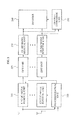
- FIG. 2 is a block diagram illustrating an example of a decoding apparatus using OSTBCs robust against timing errors according to an embodiment of the present invention.
- the decoding apparatus denotes an apparatus that may decode a transmission signal transmitted from an encoding apparatus of an OFDM system using the OSTBCs.
- the decoding apparatus may include a plurality of cyclic prefix removal units 210, a plurality of inverse DFT (IDPT) units 220, a plurality of guard band removal units 230, a synchronization unit 240, a channel estimation unit 250, and a decoder 260.
- IDPT inverse DFT
- a number of each of the cyclic prefix removal units 210, the IDFT units 220, and the guard band units 230 may be the same as a number of receive antennas used in the decoding apparatus, and thus may correspond to the receive antennas, respectively.
- the cyclic prefix removal unit 210 may receive the transmission signal via the receive antenna, and remove a cyclic prefix in the transmission signal.
- the IDFT unit 220 may apply an IDFT to the transmission signal in which the cyclic prefix is removed.
- the guard band removal unit 230 may remove a guard band in the inverse discrete Fourier transformed transmission signal to generate a complex matrix R.
- the synchronization unit 240 may extract a DFT window in an information symbol included in the transmission signal, and transmit the extracted DFT window to the cyclic prefix removal unit 210.
- the information symbol may be an OFDM symbol.
- the synchronization unit 240 may extract the DFT window in the information symbol using a reference signal.
- an information symbol 310 included in a transmission signal may include a DFT window 320 and a cyclic prefix interval CP 330.
- a start point 321 of the DFT window 320 when a start point 321 of the DFT window 320 is located behind an end point 331 of the cyclic prefix interval CP 330, interference may occur in a subsequent information symbol.
- a phase ramp of a radio channel status may occur in a frequency domain.
- the channel estimation unit 250 may provide the decoder 260 with channel status information H k associated with transmit and receive antennas, and a carrier corresponding to the complex matrix R,
- the channel status information H k may correspond to information of a matrix structure.
- k denotes an index of a carrier in a block
- rows and columns of the channel status information H k may correspond to transmit antennas and receive antennas, respectively.
- the channel status information H k may correspond to channel status information obtained while the cyclic prefix removal unit 210 receives the transmission signal.
- the decoder 260 may calculate a channel status vector with respect to a complex symbol included in the complex matrix R, using the channel status information H k , and calculate an inner product between the channel status vector and the complex matrix R to thereby restore the complex symbol that is input into the encoder 110, and the complex matrix C that is a matrix of the complex symbol.
- the decoder 260 may estimate c k using r k and H k .
- the decoder 260 may generate channel status information matrices with respect to the complex symbol based on the channel status information, Specifically, the decoder 260 may apply H k to the following Equation 6, and generate channel status information matrices H ⁇ k A and H ⁇ k B including channel status information associated with complex symbol vectors x and x t* .
- H ⁇ k A H k ⁇ A k
- H ⁇ k B H k ⁇ B k .
- Equation 7 H ⁇ k A ⁇ x + H ⁇ k B ⁇ x t * + w k .
- the decoder 260 may calculate an inner product between the channel status information matrices H ⁇ k A and H ⁇ k B , and the complex matrix R according to the following Equation 8, and thereby restore the complex symbol.
- ⁇ H 0 ⁇ F denotes a Frobeniuos norm with respect to H 0 , and is defined as a sum of square values of absolute values of elements of H 0 .
- the decoder 260 may apply H k corresponding to each subcarrier index, instead of using a representative value with the assumption that H k is a constant with respect to k.
- An estimate X ⁇ with respect to the complex symbol vector may be expressed by the following Equation 9, using the above Equation 6, Equation 7, and Equation 8.
- Equation 9 An estimate X ⁇ with respect to the complex symbol vector may be expressed by the following Equation 9, using the above Equation 6, Equation 7, and Equation 8.
- an interference component may be offset and only a transmitted symbol vector and a white noise component may remain.
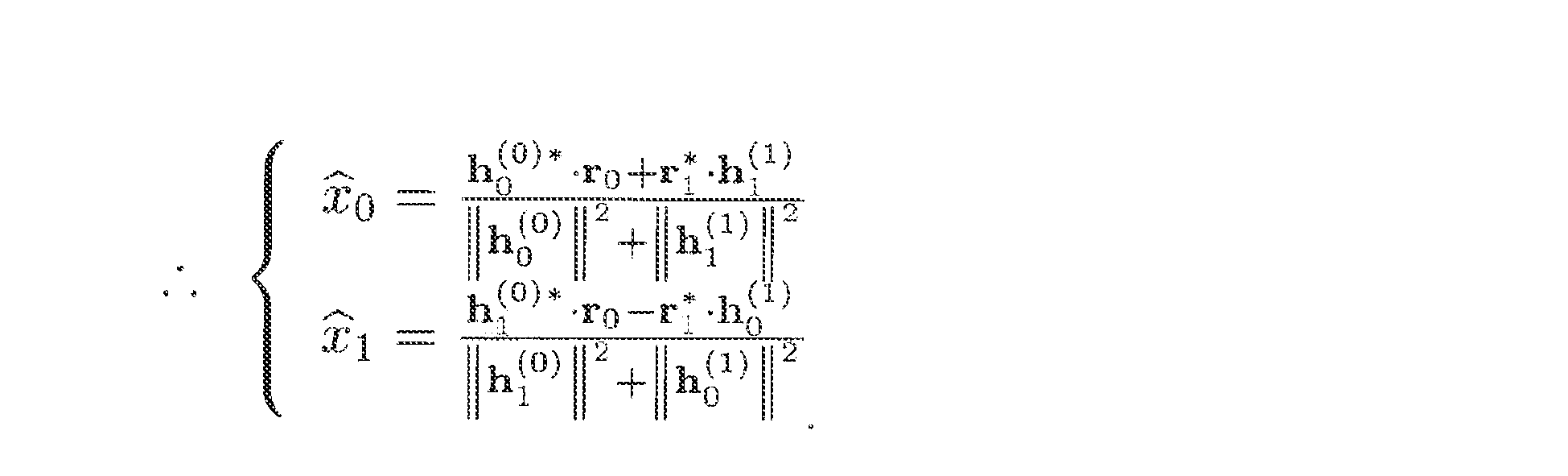
- the decoder 260 may use an Alamouti code to decode a 2 x 2 complex matrix, as shown in the following Equation 10.
- h n ( k ) denotes an n th column vector constituting the complex matrix H k .
- the decoder 260 may decode information, transmitted from the encoding apparatus using four transmit antennas, as given by the following Equation 11;
- C x 0 x 1 x 2 / 2 x 2 / 2 ⁇ x 1 * x 0 * x 2 / 2 ⁇ x 2 / 2 x 2 * / 2 - x 0 - x 0 * - x 1 - x 1 * / 2 - x 1 - x 1 * + x 0 - x 0 * / 2 x 2 * / 2 - x 2 * / 2 x 1 + x 1 * - x 0 - x 0 * / 2 - x 0 * / 2 - x 0 * - x 1 + x 1 * - x 0 - x 0 * / 2 - x 0 * - x 1 + x 1 * / 2 ⁇ r 0 r 1 r
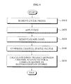
- FIG. 4 is a flowchart illustrating a decoding method using OSTBCs robust against timing errors according to an embodiment of the present invention.
- the decoding method may be performed by components constituting the decoding apparatus of FIG 2 .
- the cyclic prefix removal unit 210 may remove a cyclic prefix in a signal received via a receive antenna.
- the IDFT unit 220 may apply an IDFT to the signal in which the cyclic prefix is removed.
- the guard band removal unit 420 may remove a guard band in the inverse discrete Fourier transformed signal to generate a complex matrix R.
- the decoder 260 may generate a channel status vector offsetting an interference component. Specifically, the decoder 260 may receive, from the channel estimation unit 250, channel status information associated with a carrier corresponding to the complex matrix and transmit and receive antennas, and multiply corresponding channel status information and a matrix designating an OSTBC, for example, A k and B k of the above Equation 4, based on a carrier unit, and thereby may generate the channel status vector offsetting the interference component.
- OSTBC matrix designating an OSTBC
- a decoding apparatus and method may combine channel status information while OSTBCs are transmitted, using an orthogonality of the OSTBCs, so that a timing error may not affect a decoding result, and thereby may prevent a performance deterioration, caused by the timing error, when receiving the OSTBCs.
Landscapes
- Engineering & Computer Science (AREA)
- Computer Networks & Wireless Communication (AREA)
- Signal Processing (AREA)
- Quality & Reliability (AREA)
- Radio Transmission System (AREA)
Abstract
Provided is an apparatus and method for decoding orthogonal space-time block codes (OSTBCs), which are robust against timing errors, The decoding apparatus may include: a cyclic prefix removal unit; an inverse discrete Fourier transform (IDFT) unit; a guard band removal unit which generates a complex matrix; a channel estimation unit to transmit a carrier corresponding to the complex matrix and channel status information associated with transmit and receive antennas; and a decoder to calculate a channel status vector with respect to a complex symbol included in the complex matrix, using the channel status information, and to calculate the inner product of the channel status vector and the complex matrix, to restore the complex symbol.
Description
- The present invention relates to a decoding apparatus and method using orthogonal space-time block codes (OSTBCs) robust against timing errors, and more particularly, to a decoding apparatus and method that may prevent a performance deterioration, caused by timing errors, using an orthogonality of OSTBCs.
- According to a research regarding a decoding apparatus transmitting complex symbols using a plurality of transmit antennas to enhance a communication reliability, in a scheme where symbol vectors transmitted via the transmit antennas, respectively, are orthogonal to each other, the communication reliability may be maximized. The above scheme is referred to as an orthogonal space-time block code (OSTBC) scheme and is adopted for a plurality of mobile communication technology standards such as a 3rd Generation Partnership Project (3GPP) Long Term Evolution (LTE), and the like.
- When a channel status is uniformly maintained within a frequency band used for transmission of a code block, the OSTBC scheme may configure an optimal maximum likelihood decoding with a low linear filtering in an aspect of an error rate, However, a channel status may vary upon circumstances such as a multi-path fading phenomenon. In the multi-path fading phenomenon, since distribution paths having a different delay time between a transmission end and a reception end due to a reflector and the like are formed, the channel status may have a frequency selectivity. When the channel status varies, the orthogonality may be broken in the reception end and thereby the effect may decrease.
- Also, even in a case where the multi-path fading phenomenon is negligible due to a small delay time difference between the distribution paths, when a timing error occurs, a certain phase difference may occur in a channel status between adjacent carriers whereby the orthogonality may be broken in the reception end and the effect may decrease.
- In this instance, an arbitrariness of the frequency selectivity of the channel status is great due to the multi-path fading phenomenon and thus there are some constraints on removing the arbitrariness. However, a change caused by the timing error has a regularity and thus may be different from the aforementioned example.
- Accordingly, there is a need for a decoding apparatus and method that may perform decoding using an orthogonality of OSTBCs, so that a timing error may not affect a decoding result
- An aspect of the present invention provides a decoding apparatus and method that may combine channel status information while orthogonal space-time block codes (OSTBCs) are transmitted, using an orthogonality of the OSTBCs, so that a timing error may not affect a decoding result, and thereby may prevent a performance deterioration, caused by the timing error, when receiving the OSTBCs.
- According to an aspect of the present invention, there is provided a decoding apparatus using OSTBCs robust against timing errors, the decoding apparatus including: a cyclic prefix removal unit to receive a signal, and to remove a cyclic prefix in the received signal; an inverse discrete Fourier transform (IDFT) unit to apply an IDFR to the signal in which the cyclic prefix is removed; a guard band removal unit to remove, a guard band in the inverse discrete Fourier transformed signal, and to generate a complex matrix; a channel estimation unit to transmit a carrier corresponding to the complex matrix and channel status information associated with transmit and receive antennas; and a decoder to calculate a channel status vector with respect to a complex symbol included in the complex matrix, using the channel status information, and to calculate an inner product between the channel status vector and the complex matrix, to thereby restore the complex symbol.
- According to embodiments of the present invention, it is possible to combine channel status information while orthogonal space-time block codes (OSTBCs) are transmitted, using an orthogonality of the OSTBCs, so that a timing error may not affect a decoding result, and thereby may prevent a performance deterioration, caused by the timing error, when receiving the OSTBCs.
- These and/or other aspects, features, and advantages of the invention will become apparent and more readily appreciated from the following description of exemplary embodiments, taken in conjunction with the accompanying drawings of which:
-
FIG. 1 is a block diagram illustrating an example of an encoding apparatus using orthogonal space-time block codes (OSTBCs) in an orthogonal frequency division multiplexing (OFDM) system according to an embodiment of the present invention; -
FIG 2 is a block diagram illustrating an example of a decoding apparatus using OSTBCs robust against timing errors according to an embodiment of the present invention; -
FIG. 3 is a diagram illustrating a configuration of an information symbol included in a received signal in a decoding apparatus using OSTBCs robust against timing errors according to an embodiment of the present invention; and -
FIG. 4 is a flowchart illustrating a decoding method using OSTBCs robust against timing errors according to an embodiment of the present invention. - Reference will now be made in detail to exemplary embodiments of the present invention, examples of which are illustrated in the accompanying drawings, wherein like reference numerals refer to the like elements throughout. Exemplary embodiments are described below to explain the present invention by referring to the figures.
-
FIG. 1 is a block diagram illustrating an example of an encoding apparatus using orthogonal space-time block codes (OSTBCs) in an orthogonal frequency division multiplexing (OFDM) system according to an embodiment of the present invention. - As shown in
FIG. 1 , the encoding apparatus may include anencoder 110, a plurality of guardband insertion units 120, a plurality of discrete Fourier transform (DFT)units 130, and a plurality of cyclicprefix insertion units 140. - Here, a number of each of the guard
band insertions units 120, theDFT units 130, and the cyclicprefix insertion units 140 may be the same as a number of transmit antennas used in the encoding apparatus, and thereby correspond to the transmit antennas, respectively. - The
encoder 110 may map an N x K complex matrix C and a symbol block Xl = [x 0(l) ··· x S-1(l)] t including S complex symbols using an OSTBC technology. Each row of the complex matrix C and a transmit antenna connected to the cyclicprefix insertion unit 140 may have a one-to-one correspondence relationship. An adjacent column of the complex matrix C may map an adjacent carrier. - Here, when a conjugate transpose and a transpose are expressed by x* and x1 with respect to a complex vector x, and a block index l is omitted, each element of the complex matrix C may be expressed by a linear combination of complex symbols x 0 .....x S-1 and complex conjugates. Specifically, complex matrices Ak and Bk satisfying the following Equation 1 may exist:

where ck denotes a kth column vector of the complex matrix C, and k denotes an integer greater than or equal to zero and less than K. - Also, row vectors of the complex matrix C may be orthogonal to each other and may have a norm. Specifically, the row vectors may satisfy the following Equation 2:

- Also, according to the above Equation 1 and Equation 2, the complex matrix C may satisfy the following Equation 3 and Equation 4:


- Here, G may be an M x N complex matrix, and Tr(G) denotes a sum of diagonal elements of the complex matrix G.
- The guard
band insertion unit 120 may insert a guard band into the complex matrix. - The
DFT unit 130 may apply a DFT to the complex matrix with the inserted guard band. - The
cyclic prefix unit 140 may insert a cyclic prefix into the discrete Fourier transformed complex matrix to generate a transmission signal, and may transmit the transmission signal via the transmit antenna. -
FIG. 2 is a block diagram illustrating an example of a decoding apparatus using OSTBCs robust against timing errors according to an embodiment of the present invention. - The decoding apparatus denotes an apparatus that may decode a transmission signal transmitted from an encoding apparatus of an OFDM system using the OSTBCs. Referring to
FIG 2 , the decoding apparatus may include a plurality of cyclicprefix removal units 210, a plurality of inverse DFT (IDPT)units 220, a plurality of guardband removal units 230, asynchronization unit 240, achannel estimation unit 250, and adecoder 260. - Here, a number of each of the cyclic
prefix removal units 210, theIDFT units 220, and theguard band units 230 may be the same as a number of receive antennas used in the decoding apparatus, and thus may correspond to the receive antennas, respectively. - The cyclic
prefix removal unit 210 may receive the transmission signal via the receive antenna, and remove a cyclic prefix in the transmission signal. - The
IDFT unit 220 may apply an IDFT to the transmission signal in which the cyclic prefix is removed. - The guard
band removal unit 230 may remove a guard band in the inverse discrete Fourier transformed transmission signal to generate a complex matrix R. - The
synchronization unit 240 may extract a DFT window in an information symbol included in the transmission signal, and transmit the extracted DFT window to the cyclicprefix removal unit 210. Here, the information symbol may be an OFDM symbol. - Specifically, the
synchronization unit 240 may extract the DFT window in the information symbol using a reference signal. - As shown in
FIG 3 , aninformation symbol 310 included in a transmission signal may include a DFTwindow 320 and a cyclicprefix interval CP 330. - Here, when a
start point 321 of the DFTwindow 320 is located behind anend point 331 of the cyclicprefix interval CP 330, interference may occur in a subsequent information symbol. When thestart point 321 of the DFTwindow 320 is located ahead of theend point 331 of the cyclicprefix interval CP 330, a phase ramp of a radio channel status may occur in a frequency domain. - The
channel estimation unit 250 may provide thedecoder 260 with channel status information Hk associated with transmit and receive antennas, and a carrier corresponding to the complex matrix R, - The channel status information Hk may correspond to information of a matrix structure. Here, k denotes an index of a carrier in a block, and rows and columns of the channel status information Hk may correspond to transmit antennas and receive antennas, respectively.
- Also, the channel status information Hk may correspond to channel status information obtained while the cyclic
prefix removal unit 210 receives the transmission signal. - The
decoder 260 may calculate a channel status vector with respect to a complex symbol included in the complex matrix R, using the channel status information Hk, and calculate an inner product between the channel status vector and the complex matrix R to thereby restore the complex symbol that is input into theencoder 110, and the complex matrix C that is a matrix of the complex symbol. - A kth column vector rk of the complex matrix R transmitted from the
guard band 230 to thedecoder 260 may satisfy the following Equation 5:
where ck denotes a kth column of the complex matrix C, and wk denotes white noise according to a normal distribution. Specifically, thedecoder 260 may estimate ck using rk and Hk. - The
decoder 260 may generate channel status information matrices with respect to the complex symbol based on the channel status information, Specifically, thedecoder 260 may apply Hk to the following Equation 6, and generate channel status information matrices


- Here, k denotes a subcarrier index of a block, and the complex vector rk may satisfy the following Equation 7, derived from the above Equation 5 and Equation 6:

- The
decoder 260 may calculate an inner product between the channel status information matrices


- While calculating the channel status information matrices


decoder 260 may apply Hk corresponding to each subcarrier index, instead of using a representative value with the assumption that Hk is a constant with respect to k. - An estimate X̂ with respect to the complex symbol vector may be expressed by the following Equation 9, using the above Equation 6, Equation 7, and Equation 8. Here, due to a characteristic of OSTBCs described in the above Equation 3 and Equation 4, where, only H k *H k are uniform regardless of a fact that a value of H k varies with respect to k, an interference component may be offset and only a transmitted symbol vector and a white noise component may remain.
- In particular, when a relationship of H k = ψ(k) · H 0 where υ(k)*υ(k) = 1 is established due to a timing error, the condition that H k * H k should be uniform is satisfied. Therefore, it can be known that a decoding method proposed in the present invention is robust against the timing error. Also, when a unitary matrix V satisfying H k = V H0 exists, the interference component may be offset.

- For example, the
decoder 260 may use an Alamouti code to decode a 2 x 2 complex matrix, as shown in the following Equation 10. Here, h n (k) denotes an nth column vector constituting the complex matrix H k .
- Also, the decoder 260 may decode information, transmitted from the encoding apparatus using four transmit antennas, as given by the following Equation 11;


-
FIG. 4 is a flowchart illustrating a decoding method using OSTBCs robust against timing errors according to an embodiment of the present invention. The decoding method may be performed by components constituting the decoding apparatus ofFIG 2 . - In operation S410, the cyclic
prefix removal unit 210 may remove a cyclic prefix in a signal received via a receive antenna. - In operation S420, the
IDFT unit 220 may apply an IDFT to the signal in which the cyclic prefix is removed. - In operation S430, the guard
band removal unit 420 may remove a guard band in the inverse discrete Fourier transformed signal to generate a complex matrix R. - In operation S440, the
decoder 260 may generate a channel status vector offsetting an interference component. Specifically, thedecoder 260 may receive, from thechannel estimation unit 250, channel status information associated with a carrier corresponding to the complex matrix and transmit and receive antennas, and multiply corresponding channel status information and a matrix designating an OSTBC, for example, Ak and Bk of the above Equation 4, based on a carrier unit, and thereby may generate the channel status vector offsetting the interference component. - As described above, according to an embodiment of the present invention, there may be provided a decoding apparatus and method that may combine channel status information while OSTBCs are transmitted, using an orthogonality of the OSTBCs, so that a timing error may not affect a decoding result, and thereby may prevent a performance deterioration, caused by the timing error, when receiving the OSTBCs.
- Although a few exemplary embodiments of the present invention have been shown and described, the present invention is not limited to the described exemplary embodiments. Instead, it would be appreciated by those skilled in the art that changes may be made to these exemplary embodiments without departing from the principles
of the invention, the scope of which is defined by the claims and their equivalents.
Claims (7)
- A decoding apparatus using orthogonal space-time block codes robust against timing errors, the decoding apparatus comprising:a cyclic prefix removal unit to receive a signal, and to remove a cyclic prefix in the received signal;an inverse discrete Fourier transform (IDFT) unit to apply an IDFT to the signal in which the cyclic prefix is removed;a guard band removal unit to remove a guard band in the inverse discrete Fourier transformed signal, and to generate a complex matrix;a channel estimation unit to transmit a carrier corresponding to the complex matrix and channel status information associated with transmit and receive antennas; anda decoder to calculate a channel status vector with respect to a complex symbol included in the complex matrix, using the channel status information, and to calculate an inner product between the channel status vector and the complex matrix, to thereby restore the complex symbol.
- The decoding apparatus of claim 1, wherein the channel status information is associated with a channel status while the cyclic prefix removal unit receives the signal.
- The decoding apparatus of claim 1, wherein the channel status information is in a form of a matrix that includes a row corresponding to the receive antenna and a column corresponding to the transmit antenna.
- The decoding apparatus of claim 3, wherein the decoder generates channel status information matrices with respect to complex symbols based on the channel status information, and combines the channel status information matrices to constitute, the channel status vector that is a single information matrix.
- A decoding method using orthogonal space-time block codes robust against timing errors, the method comprising:generating a complex matrix based on a received signal;transmitting a carrier corresponding to the complex matrix and channel status information associated with transmit and receive antennas;calculating a channel status vector with respect to a complex symbol included in the complex matrix, using the channel status information; andcalculating an inner product between the channel status vector and the complex matrix to restore the complex symbol.
- The method of claim 5, wherein the calculating of the channel status vector comprises:multiplying the channel status information and a complex number of the complex symbol to generate channel status information matrices with respect to the complex symbol; andcombining the channel status information matrices to generate the channel status vector that is a single information matrix.
- The method of claim 5, wherein the generating of the complex matrix comprises:removing a cyclic prefix in the received signal;applying an IDFT to the signal in which the cyclic prefix is removed; andremoving a guard band in the inverse discrete Fourier transformed signal to generate the complex matrix.
Applications Claiming Priority (1)
| Application Number | Priority Date | Filing Date | Title |
|---|---|---|---|
| KR1020090038066A KR101236616B1 (en) | 2009-04-30 | 2009-04-30 | Decoder and decoding method using orthogonal space-time block codes robust to timing errors |
Publications (1)
| Publication Number | Publication Date |
|---|---|
| EP2247050A2 true EP2247050A2 (en) | 2010-11-03 |
Family
ID=42358683
Family Applications (1)
| Application Number | Title | Priority Date | Filing Date |
|---|---|---|---|
| EP09168680A Withdrawn EP2247050A2 (en) | 2009-04-30 | 2009-08-26 | Apparatus and method for decoding orthogonal space-time block codes which are robust against timing errors |
Country Status (3)
| Country | Link |
|---|---|
| US (1) | US20100278277A1 (en) |
| EP (1) | EP2247050A2 (en) |
| KR (1) | KR101236616B1 (en) |
Families Citing this family (2)
| Publication number | Priority date | Publication date | Assignee | Title |
|---|---|---|---|---|
| US10211953B2 (en) * | 2017-02-07 | 2019-02-19 | Qualcomm Incorporated | Antenna diversity schemes |
| US10614609B2 (en) * | 2017-07-19 | 2020-04-07 | Mediatek Inc. | Method and apparatus for reduction of artifacts at discontinuous boundaries in coded virtual-reality images |
Family Cites Families (6)
| Publication number | Priority date | Publication date | Assignee | Title |
|---|---|---|---|---|
| EP1283614A1 (en) * | 2001-08-10 | 2003-02-12 | TELEFONAKTIEBOLAGET L M ERICSSON (publ) | Channel estimation in a multicarrier transmit diversity system |
| US7301893B2 (en) | 2001-11-21 | 2007-11-27 | Texas Instruments Incorporated | Linear space-time block code with block STTD structure |
| US7756002B2 (en) * | 2003-01-30 | 2010-07-13 | Texas Instruments Incorporated | Time-frequency interleaved orthogonal frequency division multiplexing ultra wide band physical layer |
| CN101496332B (en) * | 2006-07-20 | 2015-11-25 | 英特尔公司 | Method and apparatus for improving multi-carrier MIMO channel performance using Hadamard transform |
| US8275055B2 (en) * | 2007-11-20 | 2012-09-25 | Her Majesty The Queen In Right Of Canada, As Represented By The Minister Of Industry, Through The Communications Research Centre Canada | Receiver for differentially modulated multicarrier signals |
| US20100226448A1 (en) * | 2009-03-05 | 2010-09-09 | Paul Wilkinson Dent | Channel extrapolation from one frequency and time to another |
-
2009
- 2009-04-30 KR KR1020090038066A patent/KR101236616B1/en not_active Expired - Fee Related
- 2009-08-25 US US12/547,035 patent/US20100278277A1/en not_active Abandoned
- 2009-08-26 EP EP09168680A patent/EP2247050A2/en not_active Withdrawn
Also Published As
| Publication number | Publication date |
|---|---|
| KR101236616B1 (en) | 2013-02-22 |
| KR20100119116A (en) | 2010-11-09 |
| US20100278277A1 (en) | 2010-11-04 |
Similar Documents
| Publication | Publication Date | Title |
|---|---|---|
| JP5027255B2 (en) | Ratio data emission method, radiators and receivers using the method | |
| US10187124B2 (en) | Beam-change indication for channel estimation enhancement | |
| US7269127B2 (en) | Preamble structures for single-input, single-output (SISO) and multi-input, multi-output (MIMO) communication systems | |
| EP1821481B1 (en) | OFDM - MIMO radio frequency transmission system | |
| US8654879B2 (en) | Multi-antenna channel estimation method based on polyphase decomposition | |
| US8548101B2 (en) | Demodulation method and demodulator for orthogonal frequency multiplexing—multiple input multiple output system | |
| US20150055725A1 (en) | Pilot Design for Wireless System | |
| EP2158736B1 (en) | OFDM-MIMO radio frequency transmission system | |
| EP2755349A1 (en) | Scattered pilot pattern and channel estimation method for MIMO-OFDM systems | |
| US20060227891A1 (en) | Method of channel estimation for MIMO-OFDM using phase rotated low overhead preamble | |
| EP1415428B1 (en) | Channel estimation in a multi carrier transmit diversity system | |
| US20110207399A1 (en) | Cyclic prefix schemes | |
| US9350590B2 (en) | Method, system and apparatus for carrier frequency offset correction and channel estimation | |
| CN105049095B (en) | The diversity receiving/transmission method and device of SC-MIMO system double fluid triantennaries or four antennas | |
| EP1804410B1 (en) | Apparatus and method for transmitting and receiving a signal in a wireless communcation system | |
| US9136920B2 (en) | Reception apparatus and reception method | |
| US8073070B2 (en) | Multi-pilot generation method and detection method in multi-antenna communication system | |
| US20100278277A1 (en) | Decoding apparatus and method using orthogonal space-time block codes robust timing errors | |
| EP2398200A1 (en) | Method and device for transferring data and information enabling an estimate of a wireless link | |
| US7403571B2 (en) | Method for eliminating reception interference signal of space-time block coded orthogonal frequency division-multiplexing system in high-speed mobile channel | |
| US11652542B2 (en) | Device and method for inserting quadruplet and device and method for extracting quadruplet | |
| KR20140046707A (en) | Method for muti antenna relay transmission/reception for ofdm system | |
| KR101288927B1 (en) | Transmitter and Receiver thereof | |
| EP2319217B1 (en) | Method and apparatus for receiving numerical signals transmitted by coded frequency division multiplexing for transmission systems, in particular of the spatial diversity type | |
| KR101233281B1 (en) | Transmitter and Receiver thereof |
Legal Events
| Date | Code | Title | Description |
|---|---|---|---|
| PUAI | Public reference made under article 153(3) epc to a published international application that has entered the european phase |
Free format text: ORIGINAL CODE: 0009012 |
|
| AK | Designated contracting states |
Kind code of ref document: A2 Designated state(s): AT BE BG CH CY CZ DE DK EE ES FI FR GB GR HR HU IE IS IT LI LT LU LV MC MK MT NL NO PL PT RO SE SI SK SM TR |
|
| AX | Request for extension of the european patent |
Extension state: AL BA RS |
|
| STAA | Information on the status of an ep patent application or granted ep patent |
Free format text: STATUS: THE APPLICATION HAS BEEN WITHDRAWN |
|
| 18W | Application withdrawn |
Effective date: 20120706 |