EP2246936A1 - Antenna and wireless communication device - Google Patents
Antenna and wireless communication device Download PDFInfo
- Publication number
- EP2246936A1 EP2246936A1 EP09703740A EP09703740A EP2246936A1 EP 2246936 A1 EP2246936 A1 EP 2246936A1 EP 09703740 A EP09703740 A EP 09703740A EP 09703740 A EP09703740 A EP 09703740A EP 2246936 A1 EP2246936 A1 EP 2246936A1
- Authority
- EP
- European Patent Office
- Prior art keywords
- antenna
- radiation
- conductor
- resonance frequency
- ghz
- Prior art date
- Legal status (The legal status is an assumption and is not a legal conclusion. Google has not performed a legal analysis and makes no representation as to the accuracy of the status listed.)
- Withdrawn
Links
Images




Classifications
-
- H—ELECTRICITY
- H01—ELECTRIC ELEMENTS
- H01Q—ANTENNAS, i.e. RADIO AERIALS
- H01Q9/00—Electrically-short antennas having dimensions not more than twice the operating wavelength and consisting of conductive active radiating elements
- H01Q9/04—Resonant antennas
- H01Q9/30—Resonant antennas with feed to end of elongated active element, e.g. unipole
- H01Q9/42—Resonant antennas with feed to end of elongated active element, e.g. unipole with folded element, the folded parts being spaced apart a small fraction of the operating wavelength
-
- H—ELECTRICITY
- H01—ELECTRIC ELEMENTS
- H01Q—ANTENNAS, i.e. RADIO AERIALS
- H01Q1/00—Details of, or arrangements associated with, antennas
- H01Q1/12—Supports; Mounting means
- H01Q1/22—Supports; Mounting means by structural association with other equipment or articles
- H01Q1/24—Supports; Mounting means by structural association with other equipment or articles with receiving set
- H01Q1/241—Supports; Mounting means by structural association with other equipment or articles with receiving set used in mobile communications, e.g. GSM
- H01Q1/242—Supports; Mounting means by structural association with other equipment or articles with receiving set used in mobile communications, e.g. GSM specially adapted for hand-held use
- H01Q1/243—Supports; Mounting means by structural association with other equipment or articles with receiving set used in mobile communications, e.g. GSM specially adapted for hand-held use with built-in antennas
-
- H—ELECTRICITY
- H01—ELECTRIC ELEMENTS
- H01Q—ANTENNAS, i.e. RADIO AERIALS
- H01Q1/00—Details of, or arrangements associated with, antennas
- H01Q1/36—Structural form of radiating elements, e.g. cone, spiral, umbrella; Particular materials used therewith
-
- H—ELECTRICITY
- H01—ELECTRIC ELEMENTS
- H01Q—ANTENNAS, i.e. RADIO AERIALS
- H01Q5/00—Arrangements for simultaneous operation of antennas on two or more different wavebands, e.g. dual-band or multi-band arrangements
- H01Q5/30—Arrangements for providing operation on different wavebands
- H01Q5/307—Individual or coupled radiating elements, each element being fed in an unspecified way
- H01Q5/342—Individual or coupled radiating elements, each element being fed in an unspecified way for different propagation modes
- H01Q5/357—Individual or coupled radiating elements, each element being fed in an unspecified way for different propagation modes using a single feed point
Definitions
- the present invention relates to an antenna that is used in a wireless communication device such as a mobile phone handset that transmits and receives radio signals. More particularly, the present invention relates to an antenna that operates in frequency multibands such as the GSM band of 880 MHz to 960 MHz, the DCS band of 1710 MHz to 1880 MHz, the PCS band of 1850 MHz to 1990 MHz, and the UMTS band of 1920 MHz to 2170 MHz.
- frequency multibands such as the GSM band of 880 MHz to 960 MHz, the DCS band of 1710 MHz to 1880 MHz, the PCS band of 1850 MHz to 1990 MHz, and the UMTS band of 1920 MHz to 2170 MHz.
- antennas that can cope with multibands that are used in a mobile phone handset have been suggested.
- Examples of such antennas include antennas each having meandered slots formed on a meandered patch (see Non-Patent Document 1, for example), monopole slot antennas (see Non-Patent Document 2, for example), antennas each using a plurality of monopoles (see Non-Patent Documents 3, 4, and 5, for example), planar inverted F antennas (PIFA) (see Non-Patent Document 6, for example), and fractal antennas (see Non-Patent Document 7, for example).
- PIFA planar inverted F antennas
- Multiband antennas to be used in wireless communication devices must cope with GSM (880 MHz to 960 MHz), DCS (1710 MHz to 1880 MHz), PCS (1850 MHz to 1990 MHz), and UMTS (1920 MHz to 2170 MHz).
- the second resonance frequency band needs to be a wide band of 1710 MHz to 2170 MHz, with DCS, PCS, and UMTS being combined.
- An antenna to be mounted on a wireless communication device is required to be small in size.
- a multiband antenna is required to have such input characteristics as to secure consistency in each band, and is further required to maintain the highest possible omnidirectionality in each band.
- An antenna that has meandered slots formed on a meandered patch needs a three-dimensional installation space.
- the radiation patterns greatly vary with frequency changes, and omnidirectionality cannot be maintained.
- Non-Patent Document 2 In a monopole slot antenna (see Non-Patent Document 2, for example), slots need to be formed on a ground substrate, and therefore, it is necessary to perform processing on the substrate. Also, the radiation patterns depend on frequency, and therefore, omnidirectionality cannot be maintained.
- Non-Patent Documents 3, 4, and 5, for example a PIFA (see Non-Patent Document 6, for example), and a fractal antenna (see Non-Patent Document 7, for example)
- the radiation patterns depend on frequency, and therefore, omnidirectionality cannot be maintained as in a monopole slot antenna.
- the present invention aims to provide an antenna that is small in size, has such input characteristics as to secure consistency in each band, and is capable of maintaining omnidirectionality, and a wireless communication device that has the antenna mounted thereon.
- the inventor discovered that, if a lower arm or an upper arm is formed by folding an arm-like radiation conductor, and the radiation conductor has meandered portions, the second resonance frequency band including the high-order resonance frequency shifts to the lower frequency side or becomes wider, without a change in the first resonance frequency band including the low-order resonance frequency.
- the meandered portions are protruding portions that protrude in a direction perpendicular to the lower arm, the upper arm, or the shorting pin extending along a straight line that keeps a fixed distance from the grounded conductor.
- Each of the meandered portions may have a U-like shape, a V-like shape, or an L-like shape that is cut off at a top end.
- An antenna according to the present invention includes: a grounded conductor; a shorting pin that is formed with a conductor; and a radiation conductor that has one end connected to the grounded conductor via the shorting pin, has the other end left open, and receives power supplied from a feeding point located at the one end.
- the radiation conductor is folded at a portion between the one end and the other end, and forms a lower arm closer to the grounded conductor and a folded upper arm, with at least part of the lower arm and the upper arm having a meandered portion.
- the antenna By forming the folded upper arm and lower arm, the antenna can be made smaller in size. Also, since at least part of the upper arm or the lower arm has a meandered portion, the high-order resonance frequency can shift to the lower frequency side. Thus, the antenna according to the present invention can be small-sized and secure consistency in the input characteristics of each band. Further, omnidirectionality is maintained.
- the shorting pin has a meandered portion. According to this invention, the second resonance frequency band can be made wider.
- the radiation conductor and the shorting pin are formed with one continuous conductor line. This antenna can be easily manufactured.
- the radiation conductor is placed in the same plane as the grounded conductor.
- the grounded conductor and the radiation conductor can be formed on the same substrate.
- the radiation conductor is placed in a different plane from the grounded conductor.
- the radiation conductor can be formed on a different substrate from the grounded conductor, without a change in the resonance frequency characteristics.
- the antenna can be made smaller in size.
- the radiation conductor or the shorting pin is folded at least once along a straight line that runs parallel to the extending direction of the lower arm or the upper arm. According to this invention, the antenna can be made smaller in size and then mounted on a device, without a change in the resonance frequency characteristics.
- the folded radiation conductor is fixed to a dielectric material. According to this invention, the mounting of the antenna can be made easier, and the total length of the radiation conductor can be reduced.
- the radiation conductor is a metal line or a metal film that is formed on a flexible substrate.
- a metal line the antenna can be easily manufactured.
- a metal film the antenna can be easily manufactured by a printing technique.
- a wireless communication device includes the antenna according to the present invention. This wireless communication device can cover multibands with the small-sized antenna.
- an antenna that is small in size, has such input characteristics as to secure consistency in each band, and is capable of maintaining omnidirectionality, and a wireless communication device.
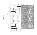
- Fig. 1 shows an example of an antenna according to this embodiment.
- the antenna 101 according to this embodiment includes a grounded conductor 11, a radiation conductor 12, and a shorting pin 13.
- the antenna 101 has the shorting pin 13 provided between the grounded conductor 11 and the radiation conductor 12.
- the shorting pin 13 is formed with the portion between the edge of the grounded conductor 11 and a feeding point 23.
- the radiation conductor 12 has one end 21 connected to the shorting pin 13, and has the other end 22 left open.
- the radiation conductor 12 is roughly divided into a lower arm 24 and an upper arm 25 formed by bending the edge of the lower arm 24.
- a meandered structure is used. Power is supplied to the grounded conductor 11 and the radiation conductor 12 of the antenna 101 via the power feeder 14.
- the one end 21 of the radiation conductor 12 is connected to the power feeder 14, and has power supplied from the feeding point 23.
- the radiation conductor 12 has the one end 21 connected to the grounded conductor 11 via the shorting pin 13, and has the other end 22 left open.
- the total length of the radiation conductor 12 contributes to the operation in the first resonance frequency band including the low-order resonance frequency.
- the total length of the radiation conductor 12 is ⁇ 1 /4.
- ⁇ 1 is the wavelength of the free space of electromagnetic waves at the center frequency of the first resonance frequency band.
- the wavelength is shortened, and therefore, the wavelength ⁇ 1 is a shortened wavelength.
- the first resonance frequency band can be adjusted by arranging the length of the radiation conductor 12.
- the radiation conductor 12 is folded at a portion between the one end 21 and the other end 22, so as to form the lower arm 24 and the upper arm 25. Since the radiation conductor 12 is folded, the antenna can be made smaller.
- the lower arm 24 is the portion of the radiation conductor 12 closest to the grounded conductor 11.
- the upper arm 25 is the folded portion of the radiation conductor 12. If the upper arm 25 is not formed by bending the edge of the lower arm 24, the high-order resonance frequency f 2 is almost three times higher than the low-order resonance frequency f 1 . Accordingly, if the low-order resonance frequency f 1 is 0.9 GHz, the high-order resonance frequency f 2 is 2.7 GHz, and the objective cannot be achieved.
- the second resonance frequency band can be adjusted to a frequency band suitable for multiband operations, and accordingly, the antenna 101 can be used in multiband operations.
- the lower arm 24 is bent in a meandered fashion, and extends along a straight line that keeps a fixed distance from the grounded conductor 11. For example, as shown in Fig. 1 , if the portion of the grounded conductor 11 closest to the radiation conductor 12 is the edge of the grounded conductor 11, the lower arm 24 extends along a straight line parallel to the edge of the grounded conductor 11. Also, as shown in Fig. 14(b) , if the portion of the grounded conductor 11 closest to the radiation conductor 12 is a plane of the ground conductor 11, the lower arm 24 extends along a straight line existing in a plane parallel to the plane of the grounded conductor 11.
- the upper arm 25 is bent in a meandered fashion, and extends in a direction that is parallel to but is opposite from the extending direction of the lower arm 24. As long as the extending directions of the lower arm 24 and the upper arm 25 are parallel to each other but are opposite from each other, the folded portion of the lower arm 24 and the upper arm 25 may not have a bent form, but may be a curved form such as a semicircular form or a shape like half a doughnut.
- At least part of the lower arm 24 or the upper arm 25 has meandered portions 26.
- the meandered portions 26 of the lower arm 24 protrude toward the upper arm 25.
- the meandered portions 26 of the upper arm 25 protrude toward the lower arm 24.
- the volume of the antenna 101 can be made smaller. Accordingly, the antenna 101 is suitable as a small-size antenna that has a limited installation space.
- the positions and number of the meandered portions 26 are adjusted, so as to change the resonance frequency of the antenna.
- the second resonance frequency band including the high-order resonance frequency can be adjusted.
- resonance frequencies can be put into the frequency band to be used by mobile phone handsets.
- the antenna 101 can have the second resonance frequency band that covers GSM, DCS, PCS, and UMTS.
- the high-order resonance frequency shifts toward the lower frequency side.
- further meandered portions 26 may be formed at the upper arm 25 or the lower arm 24, so that the high-order resonance frequency further shifts toward the lower frequency side, with almost no changes being made to the low-order resonance frequency.
- the high-order resonance frequency can be caused to further shift toward the lower frequency side.
- meandered portions 26 at the lower arm 24 rather than the upper arm 25 the high-order resonance frequency can be caused to easily shift toward the lower frequency side.
- the antenna 101 can be adjusted so that consistency can be ensured in a desired frequency band, and the radiation characteristics of the antenna 101 are substantially omnidirectional, as will be apparent from the later described embodiments and examples. This is because the positions of the meandered portions 26 of the upper arm 25 and the lower arm 24 are changed so as to change the position of the current distribution contributing to radiation, and accordingly, the directionality of the radiation characteristics can be adjusted.
- the shorting pin 13 causes short-circuiting between the grounded conductor 11 and the radiation conductor 12.
- the shorting pin 13 has meandered portions 26.
- meandered portions 26 are formed at portions of the shorting pin 13 that are parallel to the edge of the grounded conductor 11.
- the resonance frequency band of the antenna 101 can be greatly widened.
- the second resonance frequency band including the high-order resonance frequency can be greatly widened.
- the radiation characteristics can be made substantially omnidirectional.
- the radiation conductor 12 and the shorting pin 13 are formed with a single continuous conductor line. It is also preferable that the radiation conductor 12 is formed with a metal line or a metal film.
- the antenna 101 is formed with a single metal line without a branch. This structure may be formed with a very thin metal film or a metal wire. In such a case, the antenna can be produced at very low costs.
- the radiation conductor 12 is formed with a metal film, it is preferable that the radiation conductor 12 is formed on a flexible substrate. If the radiation conductor 12 is formed on a flexible substrate, the radiation conductor 12 can be easily folded while maintaining the meandered portions 26.
- the antenna 101 Even if the antenna 101 is placed in an arbitrary position relative to the grounded conductor 11, the position hardly affects the characteristics. This gives a high degree of freedom to the installation position of the antenna 101, and makes the antenna design easier.
- the radiation conductor 12 may be placed in the same plane as the grounded conductor 11. Since the radiation conductor 12 is placed in the same plane as the grounded conductor 11, the grounded conductor 11 and the radiation conductor 12 can be formed on the same substrate. Alternatively, the radiation conductor 12 may be placed in a plane different from the plane in which the grounded conductor 11 is placed.
- the antenna 101 can be made smaller in size, without a change in the resonance frequency characteristics.
- the radiation conductor 12 is folded at least once along a straight line parallel to the extending direction of the lower arm 24 or the upper arm 25, or a straight line keeping a fixed distance from the nearest portion of the grounded conductor 11.
- the resonance frequency characteristics are not affected by folding the radiation conductor 12 along a straight line that keeps a fixed distance from the nearest portion of the grounded conductor 11. Accordingly, the antenna 101 can be made smaller in size, without a change being made to the resonance frequency characteristics.
- the folded radiation conductor 12 is fixed to a dielectric material. Since the radiation conductor 12 is fixed, the meandered portions 26 can be maintained.
- the radiation conductor 12 may be fixed to the edge of the substrate, for example.
- a circuit in a wireless communication device may be formed with a stack structure, and the surface of the circuit may be shielded so that the radiation conductor 12 can be fixed to the surrounding area of the circuit. Even if a shock is applied to the wireless communication device, the meandered portions 26 can be maintained, since the radiation conductor 12 is fixed. Also, since a dielectric material exists near the radiation conductor 12, the low-order resonance frequency can be made lower. Thus, the first resonance frequency band of the antenna can also be adjusted.
- Fig. 2 shows an example of an antenna according to this embodiment: Fig. 2 (a) shows the structure of the antenna; Fig. 2 (b) shows the input characteristics of the antenna; and Fig. 2(c) and Fig. 2(d) show the radiation characteristics in the x-y plane.
- the upper arm has five meandered portions.
- the size of the grounded conductor 11 is 70 ⁇ 40 mm 2 .
- the distance between the radiation conductor 12 and the grounded conductor 11 is 3 mm.
- the shorting pin 13 is connected to the edge of the grounded conductor 11.
- the power feeder 14 is connected to a spot that is located 8 mm inside from the edge of the grounded conductor 11 to which the shorting pin 13 is connected.
- the radiation conductor 12 is a planar structure, and the size of the entire radiation conductor 12 is 40 ⁇ 15 mm 2 .
- the radiation conductor 12 is formed with one line.
- the width of the radiation conductor 12 is 2 mm.
- the distance between each two adjacent portions of the radiation conductor 12 is 2 mm.
- the thickness of the radiation conductor 12 is equal to or greater than the skin depth observed at 0.9 GHz.
- the radiation conductor 12 is copper foil of 10 ⁇ m or greater in thickness.
- the radiation conductor 12 is integrally formed with the shorting pin 13. The same applies to the later described embodiments.
- the input characteristics of an antenna shown in Fig. 2 (b) are the result of a simulation of the input characteristics of the antenna 102, and are represented by the absolute values of the scattering parameter S 11 .
- the characteristic impedance of the system at the feeding point 23 of the antenna 102 is 50 ⁇ .
- the resonance frequencies at which the scattering parameter S 11 becomes small are approximately 0.85 GHz and approximately 2.00 GHz.
- the radiation characteristics in the x-y plane shown in Fig. 2(c) are the result of a simulation at the low-order resonance frequency of 0.85 GHz.
- the radiation characteristics in the x-y plane shown in Fig. 2(d) are the result of a simulation at the high-order resonance frequency of 2.00 GHz.
- the radiation characteristics are represented in the polar coordinates shown in Fig. 3 .
- the directionality in the entire structure and ⁇ -direction is as indicated by a radiation pattern 122a
- the directionality in the ⁇ -direction is as indicated by a radiation pattern 122b.
- the directionality in the entire structure and ⁇ -direction is as indicated by a radiation pattern 122c, and the directionality in the ⁇ -direction is as indicated by a radiation pattern 122d.
- excellent omnidirectionality is achieved at either resonance frequency.
- Fig. 4 shows an example of an antenna according to this embodiment: Fig. 4 (a) shows the structure of the antenna; Fig. 4(b) shows the input characteristics of the antenna; and Fig. 4(c) and Fig. 4(d) show the radiation characteristics in the x-y plane.
- the upper arm has four meandered portions, and the lower arm has one meandered portion.
- the other aspects of this structure such as the size of the grounded conductor 11, the distance between the radiation conductor 12 and the grounded conductor 11, the positions of the shorting pin 13 and the power feeder 14, the width of the radiation conductor 12, and the distance between each two adjacent portions of the radiation conductor 12, are the same as those in the second embodiment.
- the input characteristics of an antenna shown in Fig. 4 (b) are the result of a simulation of the input characteristics of the antenna 103, and are represented by the absolute values of the scattering parameter S 11 .
- the resonance frequencies at which the scattering parameter S 11 becomes small are approximately 0.85 GHz and approximately 1.95 GHz.
- the high-order resonance frequency of the antenna 103 is lower than that of the input characteristics of the antenna 102 shown in Fig. 2(b) .
- the radiation characteristics in the x-y plane shown in Fig. 4(c) are the result of a simulation at the low-order resonance frequency of 0.85 GHz.
- the radiation characteristics in the x-y plane shown in Fig. 4(d) are the result of a simulation at the high-order resonance frequency of 1.95 GHz.
- the radiation characteristics are represented in the polar coordinates shown in Fig. 3 .
- the directionality in the entire structure and ⁇ -direction is as indicated by a radiation pattern 124a
- the directionality in the ⁇ -direction is as indicated by a radiation pattern 124b.
- the directionality in the entire structure and ⁇ -direction is as indicated by a radiation pattern 124c, and the directionality in the ⁇ -direction is as indicated by a radiation pattern 124d.
- excellent omnidirectionality is achieved at either resonance frequency.
- Fig. 5 shows an example of an antenna according to this embodiment: Fig. 5 (a) shows the structure of the antenna; Fig. 5(b) shows the input characteristics of the antenna; and Fig. 5(c) and Fig. 5(d) show the radiation characteristics in the x-y plane.
- the upper arm has three meandered portions, and the lower arm has two meandered portions.
- the other aspects of this structure such as the size of the grounded conductor 11, the distance between the radiation conductor 12 and the grounded conductor 11, the positions of the shorting pin 13 and the power feeder 14, the width of the radiation conductor 12, and the distance between each two adjacent portions of the radiation conductor 12, are the same as those in the second embodiment.
- the input characteristics of an antenna shown in Fig. 5 (b) are the result of a simulation of the input characteristics of the antenna 104, and are represented by the absolute values of the scattering parameter S 11 .
- the resonance frequencies at which the scattering parameter S 11 becomes small are approximately 0.85 GHz and approximately 1.80 GHz.
- the high-order resonance frequency of the antenna 104 moves to the low frequency side that is lower than the input characteristics of the antenna 103 shown in Fig. 4(b) .
- the radiation characteristics in the x-y plane shown in Fig. 5(c) are the result of a simulation at the low-order resonance frequency of 0.85 GHz.
- the radiation characteristics in the x-y plane shown in Fig. 5(d) are the result of a simulation at the high-order resonance frequency of 1.80 GHz.
- the radiation characteristics are represented in the polar coordinates shown in Fig. 3 .
- the directionality in the entire structure and ⁇ -direction is as indicated by a radiation pattern 125a
- the directionality in the ⁇ -direction is as indicated by a radiation pattern 125b.
- the directionality in the entire structure and ⁇ -direction is as indicated by a radiation pattern 125c, and the directionality in the ⁇ -direction is as indicated by a radiation pattern 125d.
- excellent omnidirectionality is achieved at either resonance frequency.
- Fig. 6 shows an example of an antenna according to this embodiment: Fig. 6 (a) shows the structure of the antenna; Fig. 6(b) shows the input characteristics of the antenna; and Fig. 6(c) and Fig. 6(d) show the radiation characteristics in the x-y plane.
- the upper arm has two meandered portions, and the lower arm has three meandered portions.
- the other aspects of this structure such as the size of the grounded conductor 11, the distance between the radiation conductor 12 and the grounded conductor 11, the positions of the shorting pin 13 and the power feeder 14, the width of the radiation conductor 12, and the distance between each two adjacent portions of the radiation conductor 12, are the same as those in the second embodiment.
- the input characteristics of an antenna shown in Fig. 6 (b) are the result of a simulation of the input characteristics of the antenna 105, and are represented by the absolute values of the scattering parameter S 11 .
- the resonance frequencies at which the scattering parameter S 11 becomes small are approximately 0.85 GHz and approximately 1.70 GHz.
- the high-order resonance frequency of the antenna 105 is lower than that of the input characteristics of the antenna 104 of the fourth embodiment shown in Fig. 5(b) .
- the radiation characteristics in the x-y plane shown in Fig. 6(c) are the result of a simulation at the low-order resonance frequency of 0.85 GHz.
- the radiation characteristics in the x-y plane shown in Fig. 6(d) are the result of a simulation at the high-order resonance frequency of 1.70 GHz.
- the radiation characteristics are represented in the polar coordinates shown in Fig. 3 .
- the directionality in the entire structure and ⁇ -direction is as indicated by a radiation pattern 126a
- the directionality in the ⁇ -direction is as indicated by a radiation pattern 126b.
- the directionality in the entire structure and ⁇ -direction is as indicated by a radiation pattern 126c, and the directionality in the ⁇ -direction is as indicated by a radiation pattern 126d.
- excellent omnidirectionality is achieved at either resonance frequency.
- Fig. 7 shows an example of an antenna according to this embodiment: Fig. 7 (a) shows the structure of the antenna; Fig. 7(b) shows the input characteristics of the antenna; and Fig. 7(c) and Fig. 7(d) show the radiation characteristics in the x-y plane.
- the antenna 106 has the same structure as the antenna 102 shown in Fig. 2 , except that the upper arm is bent once along a straight line parallel to the extending direction of the upper arm. In a case where the plane of the grounded conductor 11 is the x-y plane, the bent upper arm is in the x-y plane. The bent line is located at a position that is 8 mm away from the base of the lower arm.
- the volume of the space occupied by the radiation conductor 12 is 40 ⁇ 8 ⁇ 7 mm 3 .
- the upper arm is not necessarily bent.
- the lower arm or the shorting pin may be bent. The same applies to the later described embodiments.
- the input characteristics of an antenna shown in Fig. 7 (b) are the result of a simulation of the input characteristics of the antenna 106, and are represented by the absolute values of the scattering parameter S 11 .
- the resonance frequencies at which the scattering parameter S 11 becomes small are approximately 0.90 GHz and approximately 2.00 GHz.
- the resonance frequencies of the antenna 106 hardly differ from those of the antenna 102 shown in Fig. 2 .
- the radiation characteristics in the x-y plane shown in Fig. 7(c) are the result of a simulation at the low-order resonance frequency of 0.90 GHz.
- the radiation characteristics in the x-y plane shown in Fig. 7(d) are the result of a simulation at the high-order resonance frequency of 2.00 GHz.
- the radiation characteristics are represented in the polar coordinates shown in Fig. 3 .
- the directionality in the entire structure and ⁇ -direction is as indicated by a radiation pattern 127a
- the directionality in the ⁇ -direction is as indicated by a radiation pattern 127b.
- the directionality in the entire structure and ⁇ -direction is as indicated by a radiation pattern 127c
- the directionality in the ⁇ -direction is as indicated by a radiation pattern 127d.
- excellent omnidirectionality is achieved at either resonance frequency.
- the bent radiation conductor 12 may be wound around a dielectric material. By doing so, not only the antenna shape can be maintained, but also the antenna size can be reduced by the dielectric material.
- Fig. 8 shows an example of an antenna according to this embodiment: Fig. 8 (a) shows the structure of the antenna; Fig. 8(b) shows the input characteristics of the antenna; and Fig. 8(c) and Fig. 8(d) show the radiation characteristics in the x-y plane.
- the antenna 107 has the same structure as the antenna 102 shown in Fig. 2 , except that the upper arm is bent twice along straight lines parallel to the extending direction of the upper arm. The first one of the bent lines is located at a position that is 5 mm away from the base of the lower arm, and the second one of the bent lines is located at a position that is further 5 mm away from the first bent line.
- the volume of the space occupied by the radiation conductor 12 is 40 ⁇ 5 ⁇ 5 mm 3 .
- the input characteristics of an antenna shown in Fig. 8 (b) are the result of a simulation of the input characteristics of the antenna 107, and are represented by the absolute values of the scattering parameter S 11 .
- the resonance frequencies at which the scattering parameter S 11 becomes small are approximately 0.90 GHz and approximately 2.00 GHz.
- the resonance frequencies of the antenna 107 hardly differ from those of the antenna 102 shown in Fig. 2 .
- the radiation characteristics in the x-y plane shown in Fig. 8(c) are the result of a simulation at the low-order resonance frequency of 0.90 GHz.
- the radiation characteristics in the x-y plane shown in Fig. 8(d) are the result of a simulation at the high-order resonance frequency of 2.00 GHz.
- the radiation characteristics are represented in the polar coordinates shown in Fig. 3 .
- the directionality in the entire structure and ⁇ -direction is as indicated by a radiation pattern 128a
- the directionality in the ⁇ -direction is as indicated by a radiation pattern 128b.
- the directionality in the entire structure and ⁇ -direction is as indicated by a radiation pattern 128c, and the directionality in the ⁇ -direction is as indicated by a radiation pattern 128d.
- excellent omnidirectionality is achieved at either resonance frequency.
- the bent radiation conductor 12 may be wound around a dielectric material. By doing so, not only the meandered portion of the radiation conductor 12 can be maintained, but also the antenna size can be reduced by the dielectric material.
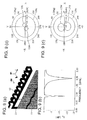
- Fig. 9 shows an example of an antenna according to this embodiment: Fig. 9 (a) shows the structure of the antenna; Fig. 9(b) shows the input characteristics of the antenna; and Fig. 9(c) and Fig. 9(d) show the radiation characteristics in the x-y plane.
- the antenna 108 has the same structure as the antenna 102 shown in Fig. 2 , except that the upper arm is bent three times along straight lines parallel to the extending direction of the upper arm.
- the first one of the bent lines is located at a position that is 4 mm away from the base of the lower arm, the second one of the bent lines is located at a position that is further 4 mm away from the first bent line, and the third one of the bent lines is located at a position that is further 4 mm away from the second bent line.
- the volume of the space occupied by the radiation conductor 12 is 40 ⁇ 4 ⁇ 4 mm 3 .
- the input characteristics of an antenna shown in Fig. 9 (b) are the result of a simulation of the input characteristics of the antenna 108, and are represented by the absolute values of the scattering parameter S 11 .
- the resonance frequencies at which the scattering parameter S 11 becomes small are approximately 0.90 GHz and approximately 2.00 GHz.
- the resonance frequencies of the antenna 108 hardly differ from those of the antenna 102 shown in Fig. 2 .
- the radiation characteristics in the x-y plane shown in Fig. 9(c) are the result of a simulation at the low-order resonance frequency of 0.90 GHz.
- the radiation characteristics in the x-y plane shown in Fig. 9(d) are the result of a simulation at the high-order resonance frequency of 2.00 GHz.
- the radiation characteristics are represented in the polar coordinates shown in Fig. 3 .
- the directionality in the entire structure and ⁇ -direction is as indicated by a radiation pattern 129a
- the directionality in the ⁇ -direction is as indicated by a radiation pattern 129b.
- the directionality in the entire structure and ⁇ -direction is as indicated by a radiation pattern 129c, and the directionality in the ⁇ -direction is as indicated by a radiation pattern 129d.
- excellent omnidirectionality is achieved in either frequency band.
- the bent radiation conductor 12 may be wound around a dielectric material. By doing so, not only the antenna shape can be maintained, but also the antenna size can be reduced by the dielectric material.
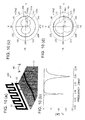
- Fig. 10 shows an example of an antenna according to this embodiment: Fig. 10 (a) shows the structure of the antenna; Fig. 10 (b) shows the input characteristics of the antenna; and Fig. 10 (c) and Fig. 10 (d) show the radiation characteristics in the x-y plane.
- the antenna 109 has the same structure as the antenna 102 shown in Fig. 2 , except that the radiation conductor 12 is placed perpendicular to the grounded conductor 11. For example, in a case where coordinate axes are adjusted to the radiation conductor 12, and the radiation conductor 12 is placed in the x-z plane, the ground conductor 11 is placed in the x-y plane.
- the input characteristics of an antenna shown in Fig. 10(b) are the result of a simulation of the input characteristics of the antenna 109, and are represented by the absolute values of the scattering parameter S 11 .
- the resonance frequencies at which the scattering parameter S 11 becomes small are approximately 0.85 GHz and approximately 2.00 GHz.
- the resonance frequencies of the antenna 109 hardly differ from those of the antenna 102 shown in Fig. 2 .
- the radiation characteristics in the x-y plane shown in Fig. 10(c) are the result of a simulation at the low-order resonance frequency of 0.85 GHz.
- the radiation characteristics in the x-y plane shown in Fig. 10(d) are the result of a simulation at the high-order resonance frequency of 2.00 GHz.
- the radiation characteristics are represented in the polar coordinates shown in Fig. 3 .
- the directionality in the entire structure is as indicated by a radiation pattern 130a
- the directionality in the ⁇ -direction is as indicated by a radiation pattern 130e
- the directionality in the ⁇ -direction is as indicated by a radiation pattern 130b.
- the directionality in the entire structure is as indicated by a radiation pattern 130c
- the directionality in the ⁇ -direction is as indicated by a radiation pattern 130f
- the directionality in the ⁇ -direction is as indicated by a radiation pattern 130d.
- excellent omnidirectionality is achieved at either resonance frequency.
- Fig. 11 shows an example of an antenna according to this embodiment: Fig. 11(a) shows the structure of the antenna; Fig. 11(b) shows the input characteristics of the antenna; and Fig. 11 (c) and Fig. 11(d) show the radiation characteristics in the x-y plane.
- the antenna 110 has the same structure as the antenna 105 shown in Fig. 6 , except that the upper arm has one meandered portions, reduced from two, and the shorting pin 13 has a meandered portion.
- the power feeder 14 is at a distance of 11 mm from the connecting point between the shorting pin 13 and the grounded conductor 11, so as to keep consistency.
- the antenna 110 is the same as the antenna 105, except that the shorting pin 13 is a meandered portion.
- the input characteristics of an antenna shown in Fig. 11(b) are the result of a simulation of the input characteristics of the antenna 110, and are represented by the absolute values of the scattering parameter S 11 .
- the resonance frequencies at which the scattering parameter S 11 becomes small are approximately 0.85 GHz and approximately 1.80 GHz.
- ⁇ -5 dB is the band from 1.45 GHz to 1.95 GHz.
- ⁇ -5 dB is the band from 1.55 GHz to 1.85 GHz in the antenna 105 shown in Fig. 6 , the second resonance frequency band is greatly widened in the antenna 110.
- the radiation characteristics in the x-y plane shown in Fig. 11(c) are the result of a simulation at the low-order resonance frequency of 0.85 GHz.
- the radiation characteristics in the x-y plane shown in Fig. 11(d) are the result of a simulation at the high-order resonance frequency of 1.80 GHz.
- the radiation characteristics are represented in the polar coordinates shown in Fig. 3 .
- the directionality in the entire structure and ⁇ -direction is as indicated by a radiation pattern 131a
- the directionality in the ⁇ -direction is as indicated by a radiation pattern 131b.
- the directionality in the entire structure and ⁇ -direction is as indicated by a radiation pattern 131c
- the directionality in the ⁇ -direction is as indicated by a radiation pattern 131d.
- excellent omnidirectionality is achieved at either resonance frequency.
- the radiation patterns 131a, 131b, 131c, and 131d are substantially the same as the radiation patterns 126a, 126b, 126c, and 126d of the antenna 105 shown in Fig. 6 .
- Fig. 12 shows an example of an antenna according to this embodiment: Fig. 12 (a) shows the structure of the antenna; Fig. 12 (b) shows the input characteristics of the antenna; and Fig. 12 (c) and Fig. 12 (d) show the radiation characteristics in the x-y plane.
- the lower arm has one meandered portion
- the upper arm has two meandered portions
- the shorting pin 13 has one meandered portion, with the findings in the second through the tenth embodiments being applied to this embodiment.
- the input characteristics of an antenna shown in Fig. 12(b) are the result of a simulation of the input characteristics of the antenna 111, and are represented by the absolute values of the scattering parameter S 11 .
- ⁇ -5 dB is the band from 0.88 GHz to 0.96 GHz
- the second resonance frequency band is the band from 1.75 GHz to 2.18 GHz.
- the first resonance frequency band and the second resonance frequency band cover GSM, PCS, and UMTS.
- the radiation characteristics in the x-y plane shown in Fig. 12(c) are the result of a simulation at the low-order resonance frequency of 0.92 GHz.
- the radiation characteristics in the x-y plane shown in Fig. 12(d) are the result of a simulation at the high-order resonance frequency of 1.94 GHz.
- the radiation characteristics are represented in the polar coordinates shown in Fig. 3 .
- the directionality in the entire structure and ⁇ -direction is as indicated by a radiation pattern 132a
- the directionality in the ⁇ -direction is as indicated by a radiation pattern 132b.
- the directionality in the entire structure and ⁇ -direction is as indicated by a radiation pattern 132c, and the directionality in the ⁇ -direction is as indicated by a radiation pattern 132d.
- excellent omnidirectionality is achieved at either resonance frequency.
- Fig. 13 shows an example of an antenna according to this embodiment: Fig. 13 (a) shows the structure of the antenna; Fig. 13 (b) shows the input characteristics of the antenna; and Fig. 13 (c) and Fig. 13 (d) show the radiation characteristics in the x-y plane.
- the lower arm has three meandered portions, the upper arm has one meandered portion, and the shorting pin 13D has one meandered portion, with the findings in the second through the tenth embodiments being applied to this embodiment.
- the input characteristics of an antenna shown in Fig. 13(b) are the result of a simulation of the input characteristics of the antenna 112, and are represented by the absolute values of the scattering parameter S 11 .
- ⁇ -5 dB is the band from 0.88 GHz to 0.96 GHz
- the second resonance frequency band is the band from 1.55 GHz to 2.12 GHz.
- the first resonance frequency band and the second resonance frequency band cover GSM, DCS, and PCS.
- the radiation characteristics in the x-y plane shown in Fig. 13(c) are the result of a simulation at the low-order resonance frequency of 0.92 GHz.
- the radiation characteristics in the x-y plane shown in Fig. 13(d) are the result of a simulation at the high-order resonance frequency of 1.94 GHz.
- the radiation characteristics are represented in the polar coordinates shown in Fig. 3 .
- the directionality in the entire structure and ⁇ -direction is as indicated by a radiation pattern 133a
- the directionality in the ⁇ -direction is as indicated by a radiation pattern 133b.
- the directionality in the entire structure and ⁇ -direction is as indicated by a radiation pattern 133c
- the directionality in the ⁇ -direction is as indicated by a radiation pattern 133d.
- excellent omnidirectionality is achieved at either resonance frequency.
- FIG. 14 shows other examples of antenna structures.
- the antenna 113 shown in Fig. 14(a) is the same as the antenna 102 of the second embodiment, except that the radiation conductor 12 has a smaller width.
- the antenna 114 shown in Fig. 14 (c) is the same as the antenna 102 of the second embodiment, except that the plane of the radiation conductor 12 deviates from the plane of the grounded conductor 11, and the radiation conductor 12 is located in a different plane from the plane of the grounded conductor 11.
- the antenna 14(b) is the same as the antenna 102 of the second embodiment, except that the radiation conductor 12 is perpendicular to the grounded conductor 11, and is placed in a different plane from the plane of the grounded conductor 11. Further, the radiation conductor 12 is placed inside the grounded conductor 11.
- the antenna 116 shown in Fig. 14 (d) is the same as the antenna 107 of the seventh embodiment, except that the bent width in the x-y plane is smaller.
- Each of the antennas 113, 114, 115, and 116 has substantially the same input characteristics and directionality as the antenna 102 of the second embodiment.
- Fig. 15 is a schematic view of a wireless communication device according to this embodiment: Fig. 15 (a) shows an example of a transmission device; and Fig. 15(b) shows an example of a reception device.
- the transmission device shown in Fig. 15 (a) includes a transmission antenna 37.
- the wireless communication device may be a transmission and reception device such as a mobile phone handset.
- the transmission antenna 37 and the reception antenna 41 can share one antenna to be a shared antenna.
- the transmission antenna 37 or the reception antenna 41 is formed with the antenna according to one of the first through the thirteenth embodiments. With this arrangement, the wireless communication device can be small in size, have such input characteristics as to secure consistency in each band, and maintain omnidirectionality.
- a local oscillation circuit 31 generates carries of 130 MHz in frequency.
- a modulation circuit 32 modulates the carries generated from the local oscillation circuit 31, in accordance with input data.
- a local oscillation circuit 33 generates carrier waves at 1.8 GHz in frequency.
- a mixer 34 frequency-transforms the signals output from the modulation circuit 32 at the oscillating frequency of 1.8 GHz of the local oscillation circuit 33.
- a bandpass filter 35 removes noise from the RF signals output from the mixer 34, and a RF amplifier 36 amplifies the signals output from the bandpass filter 35.
- the transmission antenna 37 transmits the signals output from the RF amplifier 36 as radio signals. Having the above structure and functions, the wireless communication device according to this embodiment can transmit radio signals.
- the frequencies generated by the local oscillation circuit 33 can cover not only DCS including 1.8 GHz, but also the frequencies used in multibands such as GSM, PCS, and UMTS. Thus, radio signals of frequencies corresponding to frequency multibands can be transmitted.
- the reception antenna 41 receives radio signals.
- a bandpass filter 42 removes noise from the signals output from the reception antenna 41.
- a RF amplifier 43 amplifies the signals output from the bandpass filter 42.
- a local oscillation circuit 44 generates carrier waves at the frequency of 1.8 GHz.
- a mixer 45 performs a frequency transform on the signals output from the RF amplifier 43 at the oscillation frequency of 1.8 GHz of the local oscillation circuit 44.
- a bandpass filter 46 removes noise from the signals output from the mixer 45.
- An IF amplifier 47 amplifies the signals output from the bandpass filter 46.
- a demodulation circuit 48 demodulates the signals output from the IF amplifier 47. Having the above structure and functions, the wireless communication device according to this embodiment can receive radio signals.
- the frequencies generated by the local oscillation circuit 44 can cover not only DCS including 1.8 GHz, but also the frequencies used in multibands such as GSM, PCS, and UMTS. Thus, radio signals of frequencies corresponding to frequency multibands can be transmitted.
- the antenna described in the eleventh embodiment was manufactured, and the input characteristics were measured.
- the antenna was formed with a metal wire made of copper.
- the diameter of the metal wire was 1.3 mm.
- Fig. 16 shows the values of the actually measured input characteristics of the antenna according to Example 1.
- the input characteristics are represented by the absolute values of the scattering parameter S 11 .
- ⁇ -5 dB is the band from 0.88 GHz to 0.96 GHz
- the second resonance frequency band is the band from 1.69 GHz to 2.35 GHz.
- the first resonance frequency band and the second resonance frequency band cover GSM, DCS, PCS, and UMTS.
- the same results were also obtained with a metal film made of copper. Since the values obtained through the actual measurement show excellent consistency with the corresponding simulation results, it is apparent that the other simulation results also have high reliability.
- the antenna described in the twelfth embodiment was manufactured, and the input characteristics were measured.
- the antenna was formed with a metal wire made of copper.
- the diameter of the metal wire was 1.3 mm.
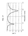
- Fig. 17 shows the values of the actually measured input characteristics of the antenna according to Example 2.
- the input characteristics are represented by the absolute values of the scattering parameter S 11 .
- ⁇ -5 dB is the band from 0.88 GHz to 1.02 GHz
- the second resonance frequency band is the band from 1.70 GHz to 2.18 GHz.
- the first resonance frequency band and the second resonance frequency band cover GSM, DCS, PCS, and UMTS.
- the same results were also obtained with a metal film made of copper. Since the values obtained through the actual measurement show excellent consistency with the corresponding simulation results, it is apparent that the other simulation results also have high reliability.
- the present invention provides an antenna that is mounted on an information terminal such as a mobile phone handset, a PDA, or a notebook PC, and enables efficient transmission and reception of radio signals in mobile phone multibands such as the GSM band from 880 MHz to 960 MHz, the DCS band from 1710 MHz to 1880 MHz, the PCS band from 1850 MHz to 1990 MHz, and the UMTS band from 1920 MHz to 2170 MHz.
- an information terminal such as a mobile phone handset, a PDA, or a notebook PC
- mobile phone multibands such as the GSM band from 880 MHz to 960 MHz, the DCS band from 1710 MHz to 1880 MHz, the PCS band from 1850 MHz to 1990 MHz, and the UMTS band from 1920 MHz to 2170 MHz.
Landscapes
- Engineering & Computer Science (AREA)
- Computer Networks & Wireless Communication (AREA)
- Waveguide Aerials (AREA)
- Support Of Aerials (AREA)
Abstract
Description
- The present invention relates to an antenna that is used in a wireless communication device such as a mobile phone handset that transmits and receives radio signals. More particularly, the present invention relates to an antenna that operates in frequency multibands such as the GSM band of 880 MHz to 960 MHz, the DCS band of 1710 MHz to 1880 MHz, the PCS band of 1850 MHz to 1990 MHz, and the UMTS band of 1920 MHz to 2170 MHz.
- Various kinds of antennas that can cope with multibands that are used in a mobile phone handset have been suggested. Examples of such antennas include antennas each having meandered slots formed on a meandered patch (see
Non-Patent Document 1, for example), monopole slot antennas (see Non-Patent Document 2, for example), antennas each using a plurality of monopoles (seeNon-Patent Documents 3, 4, and 5, for example), planar inverted F antennas (PIFA) (seeNon-Patent Document 6, for example), and fractal antennas (see Non-Patent Document 7, for example). - Multiband antennas to be used in wireless communication devices must cope with GSM (880 MHz to 960 MHz), DCS (1710 MHz to 1880 MHz), PCS (1850 MHz to 1990 MHz), and UMTS (1920 MHz to 2170 MHz). The second resonance frequency band needs to be a wide band of 1710 MHz to 2170 MHz, with DCS, PCS, and UMTS being combined.
- Non-Patent Document 1: I-T. Tang, D-B. Lin, W-L. Chen, J-H. Horng, and C-M. Li, "Compact five-band meandered PIFA by using meandered slots structure", IEEE AP-S Int. Symp., pp. 635-656, 2007
- Non-Patent Document 2: C-I. Lin, K-L. Wong, and S-H. Yeh, "Printed monopole slot antenna for multiband operation in the mobile phone", IEEE AP-S Int. Symp., pp. 629-632, 2007
- Non-Patent Document 3: C-H. Wu and K-L. Wong, "Low-profile printed monopole antenna for penta-band operation in the mobile phone", IEEE AP-S Int. Symp., pp. 3540-3543, 2007
- Non-Patent Document 4: H. Deng and Z. Feng, "A triple-band compact monopole antenna for mobile handsets", IEEE AP-S Int. Symp., pp. 2069-2072, 2007
- Non-Patent Document 5: H-C. Tung, T-F. Chen, C-Y. Chang, C-Y. Lin, and T-F. Huang, "Shorted monopole antenna for curved shape phone housing in clamshell phone", IEEE AP-S Int. Symp., pp. 1060-1063, 2007
- Non-Patent Document 6: H-J. Lee, S-H. Cho, J-K. Park, Y-H. Cho, J-M. Kim, K-H. Lee, I-Y. Lee, andJ-S. Kim, "The compact quad-band planar internal antenna for mobile handsets", IEEE AP-S Int. Symp., pp. 2045-2048, 2007
- Non-Patent Document 7 S. Yoon, C. Jung, Y. Kim, and F. D. Flaviis, "Triple-band fractal antenna design for handset system", IEEE AP-S Int. Symp., pp. 813-816, 2007
- An antenna to be mounted on a wireless communication device is required to be small in size. A multiband antenna is required to have such input characteristics as to secure consistency in each band, and is further required to maintain the highest possible omnidirectionality in each band.
- An antenna that has meandered slots formed on a meandered patch (see Non-Patent
Document 1, for example) needs a three-dimensional installation space. In such an antenna, the radiation patterns greatly vary with frequency changes, and omnidirectionality cannot be maintained. - In a monopole slot antenna (see Non-Patent Document 2, for example), slots need to be formed on a ground substrate, and therefore, it is necessary to perform processing on the substrate. Also, the radiation patterns depend on frequency, and therefore, omnidirectionality cannot be maintained.
- In an antenna using a plurality of monopoles (see Non-Patent
Documents 3, 4, and 5, for example), a PIFA (see Non-PatentDocument 6, for example), and a fractal antenna (see Non-Patent Document 7, for example), the radiation patterns depend on frequency, and therefore, omnidirectionality cannot be maintained as in a monopole slot antenna. - In view of the above circumstances, the present invention aims to provide an antenna that is small in size, has such input characteristics as to secure consistency in each band, and is capable of maintaining omnidirectionality, and a wireless communication device that has the antenna mounted thereon. Means to Solve the Problems
- The inventor discovered that, if a lower arm or an upper arm is formed by folding an arm-like radiation conductor, and the radiation conductor has meandered portions, the second resonance frequency band including the high-order resonance frequency shifts to the lower frequency side or becomes wider, without a change in the first resonance frequency band including the low-order resonance frequency. The inventor also discovered that omnidirectionality is maintained with such a structure. Here, the meandered portions are protruding portions that protrude in a direction perpendicular to the lower arm, the upper arm, or the shorting pin extending along a straight line that keeps a fixed distance from the grounded conductor. Each of the meandered portions may have a U-like shape, a V-like shape, or an L-like shape that is cut off at a top end.
- An antenna according to the present invention includes: a grounded conductor; a shorting pin that is formed with a conductor; and a radiation conductor that has one end connected to the grounded conductor via the shorting pin, has the other end left open, and receives power supplied from a feeding point located at the one end. The radiation conductor is folded at a portion between the one end and the other end, and forms a lower arm closer to the grounded conductor and a folded upper arm, with at least part of the lower arm and the upper arm having a meandered portion.
- By forming the folded upper arm and lower arm, the antenna can be made smaller in size. Also, since at least part of the upper arm or the lower arm has a meandered portion, the high-order resonance frequency can shift to the lower frequency side. Thus, the antenna according to the present invention can be small-sized and secure consistency in the input characteristics of each band. Further, omnidirectionality is maintained.
- In the antenna according to the present invention, it is preferable that the shorting pin has a meandered portion.
According to this invention, the second resonance frequency band can be made wider. - In the antenna according to the present invention, it is preferable that the radiation conductor and the shorting pin are formed with one continuous conductor line.
This antenna can be easily manufactured. - In the antenna according to the present invention, it is preferable that the radiation conductor is placed in the same plane as the grounded conductor.
According to this invention, the grounded conductor and the radiation conductor can be formed on the same substrate. - In the antenna according to the present invention, it is preferable that the radiation conductor is placed in a different plane from the grounded conductor.
According to this invention, the radiation conductor can be formed on a different substrate from the grounded conductor, without a change in the resonance frequency characteristics. Thus, the antenna can be made smaller in size. - In the antenna according to the present invention, it is preferable that the radiation conductor or the shorting pin is folded at least once along a straight line that runs parallel to the extending direction of the lower arm or the upper arm.
According to this invention, the antenna can be made smaller in size and then mounted on a device, without a change in the resonance frequency characteristics. - In the antenna according to the present invention, it is preferable that the folded radiation conductor is fixed to a dielectric material.
According to this invention, the mounting of the antenna can be made easier, and the total length of the radiation conductor can be reduced. - In the antenna according to the present invention, it is preferable that the radiation conductor is a metal line or a metal film that is formed on a flexible substrate.
With a metal line, the antenna can be easily manufactured. With a metal film, the antenna can be easily manufactured by a printing technique. - A wireless communication device according to the present invention includes the antenna according to the present invention.
This wireless communication device can cover multibands with the small-sized antenna. - According to the present invention, it is possible to provide an antenna that is small in size, has such input characteristics as to secure consistency in each band, and is capable of maintaining omnidirectionality, and a wireless communication device.
-
-
Fig. 1 shows an example of an antenna according to a first embodiment; -
Fig. 2 shows an example of an antenna according to a second embodiment:Fig. 2 (a) shows the structure of the antenna;Fig. 2 (b) shows the input characteristics of the antenna; andFig. 2(c) and Fig. 2(d) show the radiation characteristics in the x-y plane; -
Fig. 3 shows the polar coordinates used in this embodiment; -
Fig. 4 shows an example of an antenna according to a third embodiment:Fig. 4 (a) shows the structure of the antenna;Fig. 4(b) shows the input characteristics of the antenna; andFig. 4(c) and Fig. 4(d) show the radiation characteristics in the x-y plane; -
Fig. 5 shows an example of an antenna according to a fourth embodiment:Fig. 5 (a) shows the structure of the antenna;Fig. 5(b) shows the input characteristics of the antenna; andFig. 5(c) and Fig. 5(c) show the radiation characteristics in the x-y plane; -
Fig. 6 shows an example of an antenna according to a fifth embodiment:Fig. 6 (a) shows the structure of the antenna;Fig. 6(b) shows the input characteristics of the antenna; andFig. 6(c) and Fig. 6(d) show the radiation characteristics in the x-y plane; -
Fig. 7 shows an example of an antenna according to a sixth embodiment:Fig. 7 (a) shows the structure of the antenna;Fig. 7(b) shows the input characteristics of the antenna; andFig. 7(c) and Fig. 7(d) show the radiation characteristics in the x-y plane; -
Fig. 8 shows an example of an antenna according to a seventh embodiment:Fig. 8(a) shows the structure of the antenna;Fig. 8(b) shows the input characteristics of the antenna; andFig. 8(c) and Fig. 8(d) show the radiation characteristics in the x-y plane; -
Fig. 9 shows an example of an antenna according to an eighth embodiment:Fig. 9 (a) shows the structure of the antenna;Fig. 9(b) shows the input characteristics of the antenna; andFig. 9(c) and Fig. 9(d) show the radiation characteristics in the x-y plane; -
Fig. 10 shows an example of an antenna according to a ninth embodiment:Fig. 10 (a) shows the structure of the antenna;Fig. 10 (b) shows the input characteristics of the antenna; andFig. 10 (c) and Fig. 10 (d) show the radiation characteristics in the x-y plane; -
Fig. 11 shows an example of an antenna according to a tenth embodiment:Fig. 11(a) shows the structure of the antenna;Fig. 11(b) shows the input characteristics of the antenna; andFig. 11(c) and Fig. 11(d) show the radiation characteristics in the x-y plane; -
Fig. 12 shows an example of an antenna according to an eleventh embodiment:Fig. 12(a) shows the structure of the antenna;Fig. 12(b) shows the input characteristics of the antenna; andFig. 12(c) and Fig. 12(d) show the radiation characteristics in the x-y plane; -
Fig. 13 shows an example of an antenna according to a twelfth embodiment:Fig. 13(a) shows the structure of the antenna;Fig. 13(b) shows the input characteristics of the antenna; andFig. 13(c) and Fig. 13(d) show the radiation characteristics in the x-y plane; -
Fig. 14 shows examples of antenna structures:Fig. 14 (a) shows an example in which the width of the radiation conductor is smaller;Fig. 14 (b) shows an example in which the radiation conductor is placed perpendicular to the grounded conductor;Fig. 14(c) shows an example in which the radiation conductor is placed in a plane different from the grounded conductor; andFig. 14(d) shows an example in which the bent portion of the radiation conductor is narrower than that of the seventh embodiment; -
Fig. 15 is a schematic view of a wireless communication device according to a fourteenth embodiment:Fig. 15 (a) shows an example of a transmission device; andFig. 15(b) shows an example of a reception device; -
Fig. 16 shows the values of the input characteristics of the antenna actually measured in the first embodiment; and -
Fig. 17 shows the values of the input characteristics of the antenna actually measured in the second embodiment. -
- 11: grounded conductor
- 12: radiation conductor
- 13: shorting pin
- 14: power feeder
- 21: one end
- 22: the other end
- 23: feeding point
- 24: lower arm
- 25: upper arm
- 26: meandered portion
- 31: local oscillation circuit
- 32: modulation circuit
- 33: local oscillation circuit
- 34: mixer
- 35: bandpass filter
- 36: RF amplifier
- 37: transmission antenna
- 41: reception antenna
- 42: bandpass filter
- 43: RF amplifier
- 44: local oscillation circuit
- 45: mixer
- 46: bandpass filter
- 47: IF amplifier
- 48: demodulation circuit
- 101, 102, 103, 104, 105, 106, 107, 108, 109, 110, 111, 112, 113,
- 114, 115, 116: antenna
- The following is a description of embodiments of the present invention, with reference to the accompanying drawings. The embodiments described below are merely examples of structures according to the present invention, and the present invention is not limited to the following embodiments.
-
Fig. 1 shows an example of an antenna according to this embodiment. Theantenna 101 according to this embodiment includes a groundedconductor 11, aradiation conductor 12, and a shortingpin 13. Theantenna 101 has the shortingpin 13 provided between the groundedconductor 11 and theradiation conductor 12. The shortingpin 13 is formed with the portion between the edge of the groundedconductor 11 and afeeding point 23. Theradiation conductor 12 has oneend 21 connected to the shortingpin 13, and has theother end 22 left open. Theradiation conductor 12 is roughly divided into alower arm 24 and anupper arm 25 formed by bending the edge of thelower arm 24. To reduce the size of theantenna 101, a meandered structure is used. Power is supplied to the groundedconductor 11 and theradiation conductor 12 of theantenna 101 via thepower feeder 14. The oneend 21 of theradiation conductor 12 is connected to thepower feeder 14, and has power supplied from thefeeding point 23. - The
radiation conductor 12 has the oneend 21 connected to the groundedconductor 11 via the shortingpin 13, and has theother end 22 left open. The total length of theradiation conductor 12 contributes to the operation in the first resonance frequency band including the low-order resonance frequency. For example, the total length of theradiation conductor 12 is λ1/4. Here, λ1 is the wavelength of the free space of electromagnetic waves at the center frequency of the first resonance frequency band. In a case where a dielectric material exists near theradiation conductor 12, the wavelength is shortened, and therefore, the wavelength λ1 is a shortened wavelength. In this manner, in theantenna 101, the first resonance frequency band can be adjusted by arranging the length of theradiation conductor 12. - The
radiation conductor 12 is folded at a portion between the oneend 21 and theother end 22, so as to form thelower arm 24 and theupper arm 25. Since theradiation conductor 12 is folded, the antenna can be made smaller. Thelower arm 24 is the portion of theradiation conductor 12 closest to the groundedconductor 11. Theupper arm 25 is the folded portion of theradiation conductor 12. If theupper arm 25 is not formed by bending the edge of thelower arm 24, the high-order resonance frequency f2 is almost three times higher than the low-order resonance frequency f1. Accordingly, if the low-order resonance frequency f1 is 0.9 GHz, the high-order resonance frequency f2 is 2.7 GHz, and the objective cannot be achieved. Since theupper arm 25 is formed by bending the edge of thelower arm 24, the high-order resonance frequency greatly shifts to the lower frequency side, compared with the high-order resonance frequency observed in a case where the folded portion is not formed. With this arrangement, the second resonance frequency band can be adjusted to a frequency band suitable for multiband operations, and accordingly, theantenna 101 can be used in multiband operations. - The
lower arm 24 is bent in a meandered fashion, and extends along a straight line that keeps a fixed distance from the groundedconductor 11. For example, as shown inFig. 1 , if the portion of the groundedconductor 11 closest to theradiation conductor 12 is the edge of the groundedconductor 11, thelower arm 24 extends along a straight line parallel to the edge of the groundedconductor 11. Also, as shown inFig. 14(b) , if the portion of the groundedconductor 11 closest to theradiation conductor 12 is a plane of theground conductor 11, thelower arm 24 extends along a straight line existing in a plane parallel to the plane of the groundedconductor 11. Theupper arm 25 is bent in a meandered fashion, and extends in a direction that is parallel to but is opposite from the extending direction of thelower arm 24. As long as the extending directions of thelower arm 24 and theupper arm 25 are parallel to each other but are opposite from each other, the folded portion of thelower arm 24 and theupper arm 25 may not have a bent form, but may be a curved form such as a semicircular form or a shape like half a doughnut. - At least part of the
lower arm 24 or theupper arm 25 has meanderedportions 26. The meanderedportions 26 of thelower arm 24 protrude toward theupper arm 25. The meanderedportions 26 of theupper arm 25 protrude toward thelower arm 24. With the meanderedportions 26 being formed, the volume of theantenna 101 can be made smaller. Accordingly, theantenna 101 is suitable as a small-size antenna that has a limited installation space. Further, in theantenna 101, the positions and number of the meanderedportions 26 are adjusted, so as to change the resonance frequency of the antenna. Particularly, the second resonance frequency band including the high-order resonance frequency can be adjusted. With the use of the principles, resonance frequencies can be put into the frequency band to be used by mobile phone handsets. For example, theantenna 101 can have the second resonance frequency band that covers GSM, DCS, PCS, and UMTS. - Since the
radiation conductor 12 is folded, the high-order resonance frequency shifts toward the lower frequency side. In this situation, further meanderedportions 26 may be formed at theupper arm 25 or thelower arm 24, so that the high-order resonance frequency further shifts toward the lower frequency side, with almost no changes being made to the low-order resonance frequency. Here, by increasing the number of meanderedportions 26, the high-order resonance frequency can be caused to further shift toward the lower frequency side. Also, by forming meanderedportions 26 at thelower arm 24 rather than theupper arm 25, the high-order resonance frequency can be caused to easily shift toward the lower frequency side. - The
antenna 101 can be adjusted so that consistency can be ensured in a desired frequency band, and the radiation characteristics of theantenna 101 are substantially omnidirectional, as will be apparent from the later described embodiments and examples. This is because the positions of the meanderedportions 26 of theupper arm 25 and thelower arm 24 are changed so as to change the position of the current distribution contributing to radiation, and accordingly, the directionality of the radiation characteristics can be adjusted. - The shorting
pin 13 causes short-circuiting between the groundedconductor 11 and theradiation conductor 12. Here, it is preferable that the shortingpin 13 has meanderedportions 26. InFig. 1 , meanderedportions 26 are formed at portions of the shortingpin 13 that are parallel to the edge of the groundedconductor 11. As a meandered structure is formed at the shortingpin 13, the resonance frequency band of theantenna 101 can be greatly widened. Particularly, the second resonance frequency band including the high-order resonance frequency can be greatly widened. Also, by forming a meandered structure at the shortingpin 13, the radiation characteristics can be made substantially omnidirectional. - In the
antenna 101, it is preferable that theradiation conductor 12 and the shortingpin 13 are formed with a single continuous conductor line. It is also preferable that theradiation conductor 12 is formed with a metal line or a metal film. For example, except for thepower feeder 14, theantenna 101 is formed with a single metal line without a branch. This structure may be formed with a very thin metal film or a metal wire. In such a case, the antenna can be produced at very low costs. In a case where theradiation conductor 12 is formed with a metal film, it is preferable that theradiation conductor 12 is formed on a flexible substrate. If theradiation conductor 12 is formed on a flexible substrate, theradiation conductor 12 can be easily folded while maintaining the meanderedportions 26. - Even if the
antenna 101 is placed in an arbitrary position relative to the groundedconductor 11, the position hardly affects the characteristics. This gives a high degree of freedom to the installation position of theantenna 101, and makes the antenna design easier. For example, theradiation conductor 12 may be placed in the same plane as the groundedconductor 11. Since theradiation conductor 12 is placed in the same plane as the groundedconductor 11, the groundedconductor 11 and theradiation conductor 12 can be formed on the same substrate. Alternatively, theradiation conductor 12 may be placed in a plane different from the plane in which the groundedconductor 11 is placed. Theantenna 101 can be made smaller in size, without a change in the resonance frequency characteristics. - In the
antenna 101, it is preferable that theradiation conductor 12 is folded at least once along a straight line parallel to the extending direction of thelower arm 24 or theupper arm 25, or a straight line keeping a fixed distance from the nearest portion of the groundedconductor 11. As will be explained later in the seventh, the eighth, and the ninth embodiments, the resonance frequency characteristics are not affected by folding theradiation conductor 12 along a straight line that keeps a fixed distance from the nearest portion of the groundedconductor 11. Accordingly, theantenna 101 can be made smaller in size, without a change being made to the resonance frequency characteristics. - In the
antenna 101, it is preferable that the foldedradiation conductor 12 is fixed to a dielectric material. Since theradiation conductor 12 is fixed, the meanderedportions 26 can be maintained. Theradiation conductor 12 may be fixed to the edge of the substrate, for example. A circuit in a wireless communication device may be formed with a stack structure, and the surface of the circuit may be shielded so that theradiation conductor 12 can be fixed to the surrounding area of the circuit. Even if a shock is applied to the wireless communication device, the meanderedportions 26 can be maintained, since theradiation conductor 12 is fixed. Also, since a dielectric material exists near theradiation conductor 12, the low-order resonance frequency can be made lower. Thus, the first resonance frequency band of the antenna can also be adjusted. -
Fig. 2 shows an example of an antenna according to this embodiment:Fig. 2 (a) shows the structure of the antenna;Fig. 2 (b) shows the input characteristics of the antenna; andFig. 2(c) and Fig. 2(d) show the radiation characteristics in the x-y plane. In theantenna 102, the upper arm has five meandered portions. - Referring to
Fig. 2(a) , an example structure of theantenna 102 is described. The size of the groundedconductor 11 is 70 × 40 mm2. The distance between theradiation conductor 12 and the groundedconductor 11 is 3 mm. The shortingpin 13 is connected to the edge of the groundedconductor 11. Thepower feeder 14 is connected to a spot that is located 8 mm inside from the edge of the groundedconductor 11 to which the shortingpin 13 is connected. Theradiation conductor 12 is a planar structure, and the size of theentire radiation conductor 12 is 40 × 15 mm2. Theradiation conductor 12 is formed with one line. The width of theradiation conductor 12 is 2 mm. The distance between each two adjacent portions of theradiation conductor 12 is 2 mm. The thickness of theradiation conductor 12 is equal to or greater than the skin depth observed at 0.9 GHz. For example, in a case where theradiation conductor 12 is formed with a metal film, theradiation conductor 12 is copper foil of 10 µm or greater in thickness. In this embodiment, theradiation conductor 12 is integrally formed with the shortingpin 13. The same applies to the later described embodiments. - The input characteristics of an antenna shown in
Fig. 2 (b) are the result of a simulation of the input characteristics of theantenna 102, and are represented by the absolute values of the scattering parameter S11. Here, the characteristic impedance of the system at thefeeding point 23 of theantenna 102 is 50 Ω. The resonance frequencies at which the scattering parameter S11 becomes small are approximately 0.85 GHz and approximately 2.00 GHz. - The radiation characteristics in the x-y plane shown in
Fig. 2(c) are the result of a simulation at the low-order resonance frequency of 0.85 GHz. The radiation characteristics in the x-y plane shown inFig. 2(d) are the result of a simulation at the high-order resonance frequency of 2.00 GHz. The radiation characteristics are represented in the polar coordinates shown inFig. 3 . At the low-order resonance frequency of 0.85 GHz, the directionality in the entire structure and θ-direction is as indicated by aradiation pattern 122a, and the directionality in the φ-direction is as indicated by aradiation pattern 122b. At high-order resonance frequency of 2.00 GHz, the directionality in the entire structure and θ-direction is as indicated by aradiation pattern 122c, and the directionality in the φ-direction is as indicated by aradiation pattern 122d. As shown inFig. 2(c) and Fig. 2(d) , excellent omnidirectionality is achieved at either resonance frequency. -
Fig. 4 shows an example of an antenna according to this embodiment:Fig. 4 (a) shows the structure of the antenna;Fig. 4(b) shows the input characteristics of the antenna; andFig. 4(c) and Fig. 4(d) show the radiation characteristics in the x-y plane. In theantenna 103, the upper arm has four meandered portions, and the lower arm has one meandered portion. The other aspects of this structure, such as the size of the groundedconductor 11, the distance between theradiation conductor 12 and the groundedconductor 11, the positions of the shortingpin 13 and thepower feeder 14, the width of theradiation conductor 12, and the distance between each two adjacent portions of theradiation conductor 12, are the same as those in the second embodiment. - The input characteristics of an antenna shown in
Fig. 4 (b) are the result of a simulation of the input characteristics of theantenna 103, and are represented by the absolute values of the scattering parameter S11. The resonance frequencies at which the scattering parameter S11 becomes small are approximately 0.85 GHz and approximately 1.95 GHz. As can be seen from the input characteristics, the high-order resonance frequency of theantenna 103 is lower than that of the input characteristics of theantenna 102 shown inFig. 2(b) . - The radiation characteristics in the x-y plane shown in
Fig. 4(c) are the result of a simulation at the low-order resonance frequency of 0.85 GHz. The radiation characteristics in the x-y plane shown inFig. 4(d) are the result of a simulation at the high-order resonance frequency of 1.95 GHz. The radiation characteristics are represented in the polar coordinates shown inFig. 3 . At the low-order resonance frequency of 0.85 GHz, the directionality in the entire structure and θ-direction is as indicated by aradiation pattern 124a, and the directionality in the φ-direction is as indicated by aradiation pattern 124b. At high-order resonance frequency of 1.95 GHz, the directionality in the entire structure and θ-direction is as indicated by aradiation pattern 124c, and the directionality in the φ-direction is as indicated by aradiation pattern 124d. As can be seen fromFig. 4 (c) and Fig. 4(d) , excellent omnidirectionality is achieved at either resonance frequency. -
Fig. 5 shows an example of an antenna according to this embodiment:Fig. 5 (a) shows the structure of the antenna;Fig. 5(b) shows the input characteristics of the antenna; andFig. 5(c) and Fig. 5(d) show the radiation characteristics in the x-y plane. In the antenna 104, the upper arm has three meandered portions, and the lower arm has two meandered portions. The other aspects of this structure, such as the size of the groundedconductor 11, the distance between theradiation conductor 12 and the groundedconductor 11, the positions of the shortingpin 13 and thepower feeder 14, the width of theradiation conductor 12, and the distance between each two adjacent portions of theradiation conductor 12, are the same as those in the second embodiment. - The input characteristics of an antenna shown in
Fig. 5 (b) are the result of a simulation of the input characteristics of the antenna 104, and are represented by the absolute values of the scattering parameter S11. The resonance frequencies at which the scattering parameter S11 becomes small are approximately 0.85 GHz and approximately 1.80 GHz. As can be seen from the input characteristics, the high-order resonance frequency of the antenna 104 moves to the low frequency side that is lower than the input characteristics of theantenna 103 shown inFig. 4(b) . - The radiation characteristics in the x-y plane shown in
Fig. 5(c) are the result of a simulation at the low-order resonance frequency of 0.85 GHz. The radiation characteristics in the x-y plane shown inFig. 5(d) are the result of a simulation at the high-order resonance frequency of 1.80 GHz. The radiation characteristics are represented in the polar coordinates shown inFig. 3 . At the low-order resonance frequency of 0.85 GHz, the directionality in the entire structure and θ-direction is as indicated by aradiation pattern 125a, and the directionality in the φ-direction is as indicated by aradiation pattern 125b. At high-order resonance frequency of 1.80 GHz, the directionality in the entire structure and θ-direction is as indicated by aradiation pattern 125c, and the directionality in the φ-direction is as indicated by aradiation pattern 125d. As can be seen fromFig. 5 (c) and Fig. 5(d) , excellent omnidirectionality is achieved at either resonance frequency. -
Fig. 6 shows an example of an antenna according to this embodiment:Fig. 6 (a) shows the structure of the antenna;Fig. 6(b) shows the input characteristics of the antenna; andFig. 6(c) and Fig. 6(d) show the radiation characteristics in the x-y plane. In theantenna 105, the upper arm has two meandered portions, and the lower arm has three meandered portions. The other aspects of this structure, such as the size of the groundedconductor 11, the distance between theradiation conductor 12 and the groundedconductor 11, the positions of the shortingpin 13 and thepower feeder 14, the width of theradiation conductor 12, and the distance between each two adjacent portions of theradiation conductor 12, are the same as those in the second embodiment. - The input characteristics of an antenna shown in
Fig. 6 (b) are the result of a simulation of the input characteristics of theantenna 105, and are represented by the absolute values of the scattering parameter S11. The resonance frequencies at which the scattering parameter S11 becomes small are approximately 0.85 GHz and approximately 1.70 GHz. As can be seen from the input characteristics, the high-order resonance frequency of theantenna 105 is lower than that of the input characteristics of the antenna 104 of the fourth embodiment shown inFig. 5(b) . - The radiation characteristics in the x-y plane shown in
Fig. 6(c) are the result of a simulation at the low-order resonance frequency of 0.85 GHz. The radiation characteristics in the x-y plane shown inFig. 6(d) are the result of a simulation at the high-order resonance frequency of 1.70 GHz. The radiation characteristics are represented in the polar coordinates shown inFig. 3 . At the low-order resonance frequency of 0.85 GHz, the directionality in the entire structure and θ-direction is as indicated by aradiation pattern 126a, and the directionality in the φ-direction is as indicated by aradiation pattern 126b. At high-order resonance frequency of 1.70 GHz, the directionality in the entire structure and θ-direction is as indicated by aradiation pattern 126c, and the directionality in the φ-direction is as indicated by aradiation pattern 126d. As can be seen fromFig. 6 (c) and Fig. 6(d) , excellent omnidirectionality is achieved at either resonance frequency. -
Fig. 7 shows an example of an antenna according to this embodiment:Fig. 7 (a) shows the structure of the antenna;Fig. 7(b) shows the input characteristics of the antenna; andFig. 7(c) and Fig. 7(d) show the radiation characteristics in the x-y plane. Theantenna 106 has the same structure as theantenna 102 shown inFig. 2 , except that the upper arm is bent once along a straight line parallel to the extending direction of the upper arm. In a case where the plane of the groundedconductor 11 is the x-y plane, the bent upper arm is in the x-y plane. The bent line is located at a position that is 8 mm away from the base of the lower arm. The volume of the space occupied by theradiation conductor 12 is 40 × 8 × 7 mm3. Although only the upper arm is bent in this embodiment, the upper arm is not necessarily bent. In a case where the lower arm or the shorting pin has meandered portions, the lower arm or the shorting pin may be bent. The same applies to the later described embodiments. - The input characteristics of an antenna shown in
Fig. 7 (b) are the result of a simulation of the input characteristics of theantenna 106, and are represented by the absolute values of the scattering parameter S11. The resonance frequencies at which the scattering parameter S11 becomes small are approximately 0.90 GHz and approximately 2.00 GHz. The resonance frequencies of theantenna 106 hardly differ from those of theantenna 102 shown inFig. 2 . - The radiation characteristics in the x-y plane shown in
Fig. 7(c) are the result of a simulation at the low-order resonance frequency of 0.90 GHz. The radiation characteristics in the x-y plane shown inFig. 7(d) are the result of a simulation at the high-order resonance frequency of 2.00 GHz. The radiation characteristics are represented in the polar coordinates shown inFig. 3 . At the low-order resonance frequency of 0.90 GHz, the directionality in the entire structure and θ-direction is as indicated by aradiation pattern 127a, and the directionality in the φ-direction is as indicated by aradiation pattern 127b. At high-order resonance frequency of 2.00 GHz, the directionality in the entire structure and θ-direction is as indicated by aradiation pattern 127c, and the directionality in the φ-direction is as indicated by aradiation pattern 127d. As can be seen fromFig. 7 (c) and Fig. 7(d) , excellent omnidirectionality is achieved at either resonance frequency. Thebent radiation conductor 12 may be wound around a dielectric material. By doing so, not only the antenna shape can be maintained, but also the antenna size can be reduced by the dielectric material. -
Fig. 8 shows an example of an antenna according to this embodiment:Fig. 8 (a) shows the structure of the antenna;Fig. 8(b) shows the input characteristics of the antenna; andFig. 8(c) and Fig. 8(d) show the radiation characteristics in the x-y plane. Theantenna 107 has the same structure as theantenna 102 shown inFig. 2 , except that the upper arm is bent twice along straight lines parallel to the extending direction of the upper arm. The first one of the bent lines is located at a position that is 5 mm away from the base of the lower arm, and the second one of the bent lines is located at a position that is further 5 mm away from the first bent line. The volume of the space occupied by theradiation conductor 12 is 40 × 5 × 5 mm3. - The input characteristics of an antenna shown in
Fig. 8 (b) are the result of a simulation of the input characteristics of theantenna 107, and are represented by the absolute values of the scattering parameter S11. The resonance frequencies at which the scattering parameter S11 becomes small are approximately 0.90 GHz and approximately 2.00 GHz. The resonance frequencies of theantenna 107 hardly differ from those of theantenna 102 shown inFig. 2 . - The radiation characteristics in the x-y plane shown in
Fig. 8(c) are the result of a simulation at the low-order resonance frequency of 0.90 GHz. The radiation characteristics in the x-y plane shown inFig. 8(d) are the result of a simulation at the high-order resonance frequency of 2.00 GHz. The radiation characteristics are represented in the polar coordinates shown inFig. 3 . At the low-order resonance frequency of 0.90 GHz, the directionality in the entire structure and θ-direction is as indicated by aradiation pattern 128a, and the directionality in the φ-direction is as indicated by aradiation pattern 128b. At high-order resonance frequency of 2.00 GHz, the directionality in the entire structure and θ-direction is as indicated by aradiation pattern 128c, and the directionality in the φ-direction is as indicated by aradiation pattern 128d. As can be seen fromFig. 8 (c) and Fig. 8(d) , excellent omnidirectionality is achieved at either resonance frequency. Thebent radiation conductor 12 may be wound around a dielectric material. By doing so, not only the meandered portion of theradiation conductor 12 can be maintained, but also the antenna size can be reduced by the dielectric material. -
Fig. 9 shows an example of an antenna according to this embodiment:Fig. 9 (a) shows the structure of the antenna;Fig. 9(b) shows the input characteristics of the antenna; andFig. 9(c) and Fig. 9(d) show the radiation characteristics in the x-y plane. Theantenna 108 has the same structure as theantenna 102 shown inFig. 2 , except that the upper arm is bent three times along straight lines parallel to the extending direction of the upper arm. The first one of the bent lines is located at a position that is 4 mm away from the base of the lower arm, the second one of the bent lines is located at a position that is further 4 mm away from the first bent line, and the third one of the bent lines is located at a position that is further 4 mm away from the second bent line. The volume of the space occupied by theradiation conductor 12 is 40 × 4 × 4 mm3. - The input characteristics of an antenna shown in
Fig. 9 (b) are the result of a simulation of the input characteristics of theantenna 108, and are represented by the absolute values of the scattering parameter S11. The resonance frequencies at which the scattering parameter S11 becomes small are approximately 0.90 GHz and approximately 2.00 GHz. The resonance frequencies of theantenna 108 hardly differ from those of theantenna 102 shown inFig. 2 . - The radiation characteristics in the x-y plane shown in
Fig. 9(c) are the result of a simulation at the low-order resonance frequency of 0.90 GHz. The radiation characteristics in the x-y plane shown inFig. 9(d) are the result of a simulation at the high-order resonance frequency of 2.00 GHz. The radiation characteristics are represented in the polar coordinates shown inFig. 3 . At the low-order resonance frequency of 0.90 GHz, the directionality in the entire structure and θ-direction is as indicated by aradiation pattern 129a, and the directionality in the φ-direction is as indicated by aradiation pattern 129b. At high-order resonance frequency of 2.00 GHz, the directionality in the entire structure and θ-direction is as indicated by aradiation pattern 129c, and the directionality in the φ-direction is as indicated by aradiation pattern 129d. As can be seen fromFig. 9 (c) and Fig. 9(d) , excellent omnidirectionality is achieved in either frequency band. Thebent radiation conductor 12 may be wound around a dielectric material. By doing so, not only the antenna shape can be maintained, but also the antenna size can be reduced by the dielectric material. -
Fig. 10 shows an example of an antenna according to this embodiment:Fig. 10 (a) shows the structure of the antenna;Fig. 10 (b) shows the input characteristics of the antenna; andFig. 10 (c) and Fig. 10 (d) show the radiation characteristics in the x-y plane. Theantenna 109 has the same structure as theantenna 102 shown inFig. 2 , except that theradiation conductor 12 is placed perpendicular to the groundedconductor 11. For example, in a case where coordinate axes are adjusted to theradiation conductor 12, and theradiation conductor 12 is placed in the x-z plane, theground conductor 11 is placed in the x-y plane. - The input characteristics of an antenna shown in
Fig. 10(b) are the result of a simulation of the input characteristics of theantenna 109, and are represented by the absolute values of the scattering parameter S11. The resonance frequencies at which the scattering parameter S11 becomes small are approximately 0.85 GHz and approximately 2.00 GHz. The resonance frequencies of theantenna 109 hardly differ from those of theantenna 102 shown inFig. 2 . - The radiation characteristics in the x-y plane shown in
Fig. 10(c) are the result of a simulation at the low-order resonance frequency of 0.85 GHz. The radiation characteristics in the x-y plane shown inFig. 10(d) are the result of a simulation at the high-order resonance frequency of 2.00 GHz. The radiation characteristics are represented in the polar coordinates shown inFig. 3 . At the low-order resonance frequency of 0.85 GHz, the directionality in the entire structure is as indicated by aradiation pattern 130a, the directionality in the θ-direction is as indicated by aradiation pattern 130e, and the directionality in the φ-direction is as indicated by aradiation pattern 130b. At high-order resonance frequency of 2.00 GHz, the directionality in the entire structure is as indicated by aradiation pattern 130c, the directionality in the θ-direction is as indicated by aradiation pattern 130f, and the directionality in the φ-direction is as indicated by aradiation pattern 130d. As can be seen fromFig. 10(c) and Fig. 10(d) , excellent omnidirectionality is achieved at either resonance frequency. -
Fig. 11 shows an example of an antenna according to this embodiment:Fig. 11(a) shows the structure of the antenna;Fig. 11(b) shows the input characteristics of the antenna; andFig. 11 (c) and Fig. 11(d) show the radiation characteristics in the x-y plane. Theantenna 110 has the same structure as theantenna 105 shown inFig. 6 , except that the upper arm has one meandered portions, reduced from two, and the shortingpin 13 has a meandered portion. Thepower feeder 14 is at a distance of 11 mm from the connecting point between the shortingpin 13 and the groundedconductor 11, so as to keep consistency. As described above, theantenna 110 is the same as theantenna 105, except that the shortingpin 13 is a meandered portion. - The input characteristics of an antenna shown in
Fig. 11(b) are the result of a simulation of the input characteristics of theantenna 110, and are represented by the absolute values of the scattering parameter S11. The resonance frequencies at which the scattering parameter S11 becomes small are approximately 0.85 GHz and approximately 1.80 GHz. The second resonance frequency band that satisfies |S11| ≤ -5 dB is the band from 1.45 GHz to 1.95 GHz. Although the second resonance frequency band that satisfies |S11| ≤ -5 dB is the band from 1.55 GHz to 1.85 GHz in theantenna 105 shown inFig. 6 , the second resonance frequency band is greatly widened in theantenna 110. - The radiation characteristics in the x-y plane shown in
Fig. 11(c) are the result of a simulation at the low-order resonance frequency of 0.85 GHz. The radiation characteristics in the x-y plane shown inFig. 11(d) are the result of a simulation at the high-order resonance frequency of 1.80 GHz. The radiation characteristics are represented in the polar coordinates shown inFig. 3 . At the low-order resonance frequency of 0.85 GHz, the directionality in the entire structure and θ-direction is as indicated by aradiation pattern 131a, and the directionality in the φ-direction is as indicated by aradiation pattern 131b. At high-order resonance frequency of 1.80 GHz, the directionality in the entire structure and θ-direction is as indicated by aradiation pattern 131c, and the directionality in the φ-direction is as indicated by aradiation pattern 131d. As can be seen fromFig. 11(c) and Fig. 11(d) , excellent omnidirectionality is achieved at either resonance frequency. Theradiation patterns radiation patterns antenna 105 shown inFig. 6 . -
Fig. 12 shows an example of an antenna according to this embodiment:Fig. 12 (a) shows the structure of the antenna;Fig. 12 (b) shows the input characteristics of the antenna; andFig. 12 (c) and Fig. 12 (d) show the radiation characteristics in the x-y plane. In theantenna 111, the lower arm has one meandered portion, the upper arm has two meandered portions, and the shortingpin 13 has one meandered portion, with the findings in the second through the tenth embodiments being applied to this embodiment. - The input characteristics of an antenna shown in
Fig. 12(b) are the result of a simulation of the input characteristics of theantenna 111, and are represented by the absolute values of the scattering parameter S11. The first resonance frequency band that satisfies |S11| ≤ -5 dB is the band from 0.88 GHz to 0.96 GHz, and the second resonance frequency band is the band from 1.75 GHz to 2.18 GHz. The first resonance frequency band and the second resonance frequency band cover GSM, PCS, and UMTS. - The radiation characteristics in the x-y plane shown in
Fig. 12(c) are the result of a simulation at the low-order resonance frequency of 0.92 GHz. The radiation characteristics in the x-y plane shown inFig. 12(d) are the result of a simulation at the high-order resonance frequency of 1.94 GHz. The radiation characteristics are represented in the polar coordinates shown inFig. 3 . At the low-order resonance frequency of 0.92 GHz, the directionality in the entire structure and θ-direction is as indicated by aradiation pattern 132a, and the directionality in the φ-direction is as indicated by aradiation pattern 132b. At high-order resonance frequency of 1.94 GHz, the directionality in the entire structure and θ-direction is as indicated by aradiation pattern 132c, and the directionality in the φ-direction is as indicated by aradiation pattern 132d. As can be seen fromFig. 12(c) and Fig. 12(d) , excellent omnidirectionality is achieved at either resonance frequency. -
Fig. 13 shows an example of an antenna according to this embodiment:Fig. 13 (a) shows the structure of the antenna;Fig. 13 (b) shows the input characteristics of the antenna; andFig. 13 (c) and Fig. 13 (d) show the radiation characteristics in the x-y plane. In theantenna 112, the lower arm has three meandered portions, the upper arm has one meandered portion, and the shorting pin 13D has one meandered portion, with the findings in the second through the tenth embodiments being applied to this embodiment. - The input characteristics of an antenna shown in
Fig. 13(b) are the result of a simulation of the input characteristics of theantenna 112, and are represented by the absolute values of the scattering parameter S11. The first resonance frequency band that satisfies |S11| ≤ -5 dB is the band from 0.88 GHz to 0.96 GHz, and the second resonance frequency band is the band from 1.55 GHz to 2.12 GHz. The first resonance frequency band and the second resonance frequency band cover GSM, DCS, and PCS. - The radiation characteristics in the x-y plane shown in
Fig. 13(c) are the result of a simulation at the low-order resonance frequency of 0.92 GHz. The radiation characteristics in the x-y plane shown inFig. 13(d) are the result of a simulation at the high-order resonance frequency of 1.94 GHz. The radiation characteristics are represented in the polar coordinates shown inFig. 3 . At the low-order resonance frequency of 0.92 GHz, the directionality in the entire structure and θ-direction is as indicated by aradiation pattern 133a, and the directionality in the φ-direction is as indicated by aradiation pattern 133b. At high-order resonance frequency of 1.94 GHz, the directionality in the entire structure and θ-direction is as indicated by aradiation pattern 133c, and the directionality in the φ-direction is as indicated by aradiation pattern 133d. As can be seen fromFig. 13(c) and Fig. 13(d) , excellent omnidirectionality is achieved at either resonance frequency. - Antenna structures according to the present invention are not limited to those of the first through the twelfth embodiments.
Fig. 14 shows other examples of antenna structures. Theantenna 113 shown inFig. 14(a) is the same as theantenna 102 of the second embodiment, except that theradiation conductor 12 has a smaller width. Theantenna 114 shown inFig. 14 (c) is the same as theantenna 102 of the second embodiment, except that the plane of theradiation conductor 12 deviates from the plane of the groundedconductor 11, and theradiation conductor 12 is located in a different plane from the plane of the groundedconductor 11. Theantenna 115 shown inFig. 14(b) is the same as theantenna 102 of the second embodiment, except that theradiation conductor 12 is perpendicular to the groundedconductor 11, and is placed in a different plane from the plane of the groundedconductor 11. Further, theradiation conductor 12 is placed inside the groundedconductor 11. Theantenna 116 shown inFig. 14 (d) is the same as theantenna 107 of the seventh embodiment, except that the bent width in the x-y plane is smaller. Each of theantennas antenna 102 of the second embodiment. -
Fig. 15 is a schematic view of a wireless communication device according to this embodiment:Fig. 15 (a) shows an example of a transmission device; andFig. 15(b) shows an example of a reception device. The transmission device shown inFig. 15 (a) includes atransmission antenna 37. The transmission device shown inFig. 15(b) equipped with areception antenna 41. Having the transmission device and reception device, the wireless communication device may be a transmission and reception device such as a mobile phone handset. In this case, thetransmission antenna 37 and thereception antenna 41 can share one antenna to be a shared antenna. In the wireless communication device according to this embodiment, thetransmission antenna 37 or thereception antenna 41 is formed with the antenna according to one of the first through the thirteenth embodiments. With this arrangement, the wireless communication device can be small in size, have such input characteristics as to secure consistency in each band, and maintain omnidirectionality. - An example structure and functions of the transmission device shown in
Fig. 15 (a) are described. Alocal oscillation circuit 31 generates carries of 130 MHz in frequency. Amodulation circuit 32 modulates the carries generated from thelocal oscillation circuit 31, in accordance with input data. Alocal oscillation circuit 33 generates carrier waves at 1.8 GHz in frequency. Amixer 34 frequency-transforms the signals output from themodulation circuit 32 at the oscillating frequency of 1.8 GHz of thelocal oscillation circuit 33. Abandpass filter 35 removes noise from the RF signals output from themixer 34, and aRF amplifier 36 amplifies the signals output from thebandpass filter 35. Thetransmission antenna 37 transmits the signals output from theRF amplifier 36 as radio signals. Having the above structure and functions, the wireless communication device according to this embodiment can transmit radio signals. - In a case where the antenna according to one of the first through the thirteenth embodiments is used as the
transmission antenna 37, the frequencies generated by thelocal oscillation circuit 33 can cover not only DCS including 1.8 GHz, but also the frequencies used in multibands such as GSM, PCS, and UMTS. Thus, radio signals of frequencies corresponding to frequency multibands can be transmitted. - An example structure and functions of the reception device shown in
Fig. 15(b) are now described. Thereception antenna 41 receives radio signals. Abandpass filter 42 removes noise from the signals output from thereception antenna 41. ARF amplifier 43 amplifies the signals output from thebandpass filter 42. Alocal oscillation circuit 44 generates carrier waves at the frequency of 1.8 GHz. Amixer 45 performs a frequency transform on the signals output from theRF amplifier 43 at the oscillation frequency of 1.8 GHz of thelocal oscillation circuit 44. Abandpass filter 46 removes noise from the signals output from themixer 45. An IFamplifier 47 amplifies the signals output from thebandpass filter 46. Ademodulation circuit 48 demodulates the signals output from theIF amplifier 47. Having the above structure and functions, the wireless communication device according to this embodiment can receive radio signals. - In a case where the antenna according to one of the first through the thirteenth embodiments is used as the
reception antenna 41, the frequencies generated by thelocal oscillation circuit 44 can cover not only DCS including 1.8 GHz, but also the frequencies used in multibands such as GSM, PCS, and UMTS. Thus, radio signals of frequencies corresponding to frequency multibands can be transmitted. - The antenna described in the eleventh embodiment was manufactured, and the input characteristics were measured. The antenna was formed with a metal wire made of copper. The diameter of the metal wire was 1.3 mm.
Fig. 16 shows the values of the actually measured input characteristics of the antenna according to Example 1. As inFig. 12(b) , the input characteristics are represented by the absolute values of the scattering parameter S11. The first resonance frequency band that satisfies |S11| ≤ -5 dB is the band from 0.88 GHz to 0.96 GHz, and the second resonance frequency band is the band from 1.69 GHz to 2.35 GHz. The first resonance frequency band and the second resonance frequency band cover GSM, DCS, PCS, and UMTS. The same results were also obtained with a metal film made of copper. Since the values obtained through the actual measurement show excellent consistency with the corresponding simulation results, it is apparent that the other simulation results also have high reliability. - The antenna described in the twelfth embodiment was manufactured, and the input characteristics were measured. The antenna was formed with a metal wire made of copper. The diameter of the metal wire was 1.3 mm.
Fig. 17 shows the values of the actually measured input characteristics of the antenna according to Example 2. As inFig. 12(b) , the input characteristics are represented by the absolute values of the scattering parameter S11. The first resonance frequency band that satisfies |S11| ≤ -5 dB is the band from 0.88 GHz to 1.02 GHz, and the second resonance frequency band is the band from 1.70 GHz to 2.18 GHz. The first resonance frequency band and the second resonance frequency band cover GSM, DCS, PCS, and UMTS. The same results were also obtained with a metal film made of copper. Since the values obtained through the actual measurement show excellent consistency with the corresponding simulation results, it is apparent that the other simulation results also have high reliability. - The present invention provides an antenna that is mounted on an information terminal such as a mobile phone handset, a PDA, or a notebook PC, and enables efficient transmission and reception of radio signals in mobile phone multibands such as the GSM band from 880 MHz to 960 MHz, the DCS band from 1710 MHz to 1880 MHz, the PCS band from 1850 MHz to 1990 MHz, and the UMTS band from 1920 MHz to 2170 MHz.
Claims (9)
- An antenna comprising:a grounded conductor;a shorting pin that is formed with a conductor; anda radiation conductor that has one end connected to the grounded conductor via the shorting pin, has the other end left open, and receives power supplied from a feeding point located at the one end,the radiation conductor being folded at a portion between the one end and the other end, forming a lower arm closer to the grounded conductor and a folded upper arm, at least part of the lower arm and the upper arm has a meandered portion.
- The antenna according to claim 1, wherein the shorting pin has a meandered portion.
- The antenna according to claim 1, wherein the radiation conductor and the shorting pin are formed with one continuous conductor line.
- The antenna according to claim 1, wherein the radiation conductor is placed in the same plane as the grounded conductor.
- The antenna according to claim 1, wherein the radiation conductor is placed in a different plane from the grounded conductor.
- The antenna according to claim 5, wherein the radiation conductor or the shorting pin is folded at least once along a straight line that runs parallel to a extending direction of the lower arm or the upper arm.
- The antenna according to claim 6, wherein the folded radiation conductor is fixed to a dielectric material.
- The antenna according to claim 1, wherein the radiation conductor is a metal line or a metal film that is formed on a flexible substrate.
- A wireless communication device comprising the antenna according to claim 1.
Applications Claiming Priority (2)
| Application Number | Priority Date | Filing Date | Title |
|---|---|---|---|
| JP2008010471A JP5414996B2 (en) | 2008-01-21 | 2008-01-21 | Antenna and wireless communication device |
| PCT/JP2009/050816 WO2009093591A1 (en) | 2008-01-21 | 2009-01-21 | Antenna and wireless communication device |
Publications (2)
| Publication Number | Publication Date |
|---|---|
| EP2246936A1 true EP2246936A1 (en) | 2010-11-03 |
| EP2246936A4 EP2246936A4 (en) | 2016-03-09 |
Family
ID=40901099
Family Applications (1)
| Application Number | Title | Priority Date | Filing Date |
|---|---|---|---|
| EP09703740.2A Withdrawn EP2246936A4 (en) | 2008-01-21 | 2009-01-21 | Antenna and wireless communication device |
Country Status (5)
| Country | Link |
|---|---|
| US (1) | US8284106B2 (en) |
| EP (1) | EP2246936A4 (en) |
| JP (1) | JP5414996B2 (en) |
| CN (1) | CN101926048A (en) |
| WO (1) | WO2009093591A1 (en) |
Families Citing this family (50)
| Publication number | Priority date | Publication date | Assignee | Title |
|---|---|---|---|---|
| US9444213B2 (en) | 2009-03-09 | 2016-09-13 | Nucurrent, Inc. | Method for manufacture of multi-layer wire structure for high efficiency wireless communication |
| US9208942B2 (en) * | 2009-03-09 | 2015-12-08 | Nucurrent, Inc. | Multi-layer-multi-turn structure for high efficiency wireless communication |
| US11476566B2 (en) | 2009-03-09 | 2022-10-18 | Nucurrent, Inc. | Multi-layer-multi-turn structure for high efficiency wireless communication |
| US9300046B2 (en) | 2009-03-09 | 2016-03-29 | Nucurrent, Inc. | Method for manufacture of multi-layer-multi-turn high efficiency inductors |
| US9439287B2 (en) | 2009-03-09 | 2016-09-06 | Nucurrent, Inc. | Multi-layer wire structure for high efficiency wireless communication |
| US9306358B2 (en) | 2009-03-09 | 2016-04-05 | Nucurrent, Inc. | Method for manufacture of multi-layer wire structure for high efficiency wireless communication |
| US9232893B2 (en) | 2009-03-09 | 2016-01-12 | Nucurrent, Inc. | Method of operation of a multi-layer-multi-turn structure for high efficiency wireless communication |
| WO2011021236A1 (en) * | 2009-08-19 | 2011-02-24 | 株式会社 東芝 | Antenna device and information terminal device |
| US9136594B2 (en) | 2009-08-20 | 2015-09-15 | Qualcomm Incorporated | Compact multi-band planar inverted F antenna |
| US8912961B2 (en) | 2009-09-09 | 2014-12-16 | Nokia Corporation | Apparatus for wireless communication |
| TWI416799B (en) * | 2009-10-08 | 2013-11-21 | Quanta Comp Inc | Antenna device and its dual frequency antenna |
| US20110159815A1 (en) | 2009-12-25 | 2011-06-30 | Min-Chung Wu | Wireless Device |
| US10224613B2 (en) | 2009-12-25 | 2019-03-05 | Mediatek Inc. | Wireless device |
| JP5349612B2 (en) * | 2010-03-12 | 2013-11-20 | 株式会社東芝 | Communication device |
| US9160056B2 (en) | 2010-04-01 | 2015-10-13 | Apple Inc. | Multiband antennas formed from bezel bands with gaps |
| CN102918708B (en) | 2011-06-02 | 2016-06-22 | 松下电器产业株式会社 | Antenna device |
| WO2013047033A1 (en) * | 2011-09-26 | 2013-04-04 | 株式会社フジクラ | Antenna device and antenna mounting method |
| US9178270B2 (en) * | 2012-05-17 | 2015-11-03 | Futurewei Technologies, Inc. | Wireless communication device with a multiband antenna, and methods of making and using thereof |
| TWI511381B (en) * | 2013-10-09 | 2015-12-01 | Wistron Corp | Antenna |
| WO2015112008A2 (en) * | 2014-01-24 | 2015-07-30 | The Antenna Company International N.V. | Antenna module, antenna and mobile device comprising such an antenna module |
| WO2016072335A1 (en) * | 2014-11-07 | 2016-05-12 | 株式会社 村田製作所 | Wireless communication device, method for manufacturing same, and method for producing seal fitted with rfic element |
| US11205848B2 (en) | 2015-08-07 | 2021-12-21 | Nucurrent, Inc. | Method of providing a single structure multi mode antenna having a unitary body construction for wireless power transmission using magnetic field coupling |
| US9941743B2 (en) | 2015-08-07 | 2018-04-10 | Nucurrent, Inc. | Single structure multi mode antenna having a unitary body construction for wireless power transmission using magnetic field coupling |
| US9941729B2 (en) | 2015-08-07 | 2018-04-10 | Nucurrent, Inc. | Single layer multi mode antenna for wireless power transmission using magnetic field coupling |
| US10636563B2 (en) | 2015-08-07 | 2020-04-28 | Nucurrent, Inc. | Method of fabricating a single structure multi mode antenna for wireless power transmission using magnetic field coupling |
| US10063100B2 (en) | 2015-08-07 | 2018-08-28 | Nucurrent, Inc. | Electrical system incorporating a single structure multimode antenna for wireless power transmission using magnetic field coupling |
| US9941590B2 (en) | 2015-08-07 | 2018-04-10 | Nucurrent, Inc. | Single structure multi mode antenna for wireless power transmission using magnetic field coupling having magnetic shielding |
| US9960629B2 (en) | 2015-08-07 | 2018-05-01 | Nucurrent, Inc. | Method of operating a single structure multi mode antenna for wireless power transmission using magnetic field coupling |
| US10658847B2 (en) | 2015-08-07 | 2020-05-19 | Nucurrent, Inc. | Method of providing a single structure multi mode antenna for wireless power transmission using magnetic field coupling |
| US9960628B2 (en) | 2015-08-07 | 2018-05-01 | Nucurrent, Inc. | Single structure multi mode antenna having a single layer structure with coils on opposing sides for wireless power transmission using magnetic field coupling |
| US9948129B2 (en) | 2015-08-07 | 2018-04-17 | Nucurrent, Inc. | Single structure multi mode antenna for wireless power transmission using magnetic field coupling having an internal switch circuit |
| US10985465B2 (en) | 2015-08-19 | 2021-04-20 | Nucurrent, Inc. | Multi-mode wireless antenna configurations |
| JP6432693B2 (en) * | 2015-10-22 | 2018-12-05 | 株式会社村田製作所 | Antenna device |
| US9929456B2 (en) * | 2016-03-07 | 2018-03-27 | Anaren, Inc. | RF termination |
| JP6607107B2 (en) * | 2016-03-22 | 2019-11-20 | ヤマハ株式会社 | antenna |
| JP7102396B2 (en) | 2016-08-26 | 2022-07-19 | ニューカレント インコーポレイテッド | Wireless connector system |
| US10892646B2 (en) | 2016-12-09 | 2021-01-12 | Nucurrent, Inc. | Method of fabricating an antenna having a substrate configured to facilitate through-metal energy transfer via near field magnetic coupling |
| US11431200B2 (en) | 2017-02-13 | 2022-08-30 | Nucurrent, Inc. | Method of operating a wireless electrical energy transmission system |
| US10840597B2 (en) * | 2017-03-14 | 2020-11-17 | Hall Labs Llc | Broadband microstrip antenna |
| US11283295B2 (en) | 2017-05-26 | 2022-03-22 | Nucurrent, Inc. | Device orientation independent wireless transmission system |
| EP3503293B1 (en) * | 2017-12-19 | 2024-12-11 | Institut Mines Telecom - IMT Atlantique - Bretagne - Pays de la Loire | Configurable multiband wire antenna arrangement and design method thereof |
| US11227712B2 (en) | 2019-07-19 | 2022-01-18 | Nucurrent, Inc. | Preemptive thermal mitigation for wireless power systems |
| US11271430B2 (en) | 2019-07-19 | 2022-03-08 | Nucurrent, Inc. | Wireless power transfer system with extended wireless charging range |
| US11056922B1 (en) | 2020-01-03 | 2021-07-06 | Nucurrent, Inc. | Wireless power transfer system for simultaneous transfer to multiple devices |
| US11283303B2 (en) | 2020-07-24 | 2022-03-22 | Nucurrent, Inc. | Area-apportioned wireless power antenna for maximized charging volume |
| US11876386B2 (en) | 2020-12-22 | 2024-01-16 | Nucurrent, Inc. | Detection of foreign objects in large charging volume applications |
| US11881716B2 (en) | 2020-12-22 | 2024-01-23 | Nucurrent, Inc. | Ruggedized communication for wireless power systems in multi-device environments |
| US11695302B2 (en) | 2021-02-01 | 2023-07-04 | Nucurrent, Inc. | Segmented shielding for wide area wireless power transmitter |
| US11831174B2 (en) | 2022-03-01 | 2023-11-28 | Nucurrent, Inc. | Cross talk and interference mitigation in dual wireless power transmitter |
| US12003116B2 (en) | 2022-03-01 | 2024-06-04 | Nucurrent, Inc. | Wireless power transfer system for simultaneous transfer to multiple devices with cross talk and interference mitigation |
Family Cites Families (18)
| Publication number | Priority date | Publication date | Assignee | Title |
|---|---|---|---|---|
| JP3973766B2 (en) | 1997-09-19 | 2007-09-12 | 株式会社東芝 | Antenna device |
| JP2001352212A (en) * | 2000-06-08 | 2001-12-21 | Matsushita Electric Ind Co Ltd | Antenna device and wireless device using the same |
| WO2002013307A1 (en) * | 2000-08-07 | 2002-02-14 | Telefonaktiebolaget L M Ericsson | Antenna |
| JP3630622B2 (en) * | 2000-08-31 | 2005-03-16 | シャープ株式会社 | Pattern antenna and wireless communication apparatus including the same |
| JP2002100916A (en) * | 2000-09-22 | 2002-04-05 | Taiyo Yuden Co Ltd | Method for adjusting dielectric antenna and the dielectric antenna |
| JP2004032242A (en) | 2002-06-25 | 2004-01-29 | Matsushita Electric Ind Co Ltd | Antenna for portable radio |
| EP1453137A4 (en) | 2002-06-25 | 2005-02-02 | Matsushita Electric Industrial Co Ltd | ANTENNA FOR PORTABLE RADIO |
| EP2273611B1 (en) * | 2002-12-22 | 2012-02-08 | Fractus, S.A. | Multi-band monopole antenna for a mobile communications device |
| KR100450878B1 (en) * | 2003-06-13 | 2004-10-13 | 주식회사 에이스테크놀로지 | Built-in antenna with a center feed structure for wireless terminal |
| GB2404497A (en) * | 2003-07-30 | 2005-02-02 | Peter Bryan Webster | PCB mounted antenna |
| US7106259B2 (en) * | 2004-08-20 | 2006-09-12 | University Scientific Industrial Co., Ltd. | Planar inverted-F antenna |
| JP2006197528A (en) | 2005-01-14 | 2006-07-27 | Gcomm Corp | Folded linear inverse f-shaped antenna |
| US20060170610A1 (en) * | 2005-01-28 | 2006-08-03 | Tenatronics Limited | Antenna system for remote control automotive application |
| KR100787229B1 (en) * | 2005-02-04 | 2007-12-21 | 삼성전자주식회사 | Dual Band Inverse F Flatten Antenna |
| JP4710457B2 (en) | 2005-07-19 | 2011-06-29 | 三省電機株式会社 | Dual-band antenna and configuration method thereof |
| US7333065B2 (en) * | 2005-11-10 | 2008-02-19 | Receptec Holdings, Llc | Modular antenna assembly for automotive vehicles |
| US7728776B2 (en) * | 2007-09-20 | 2010-06-01 | Cheng Uei Precision Industry Co., Ltd. | Dual-band antenna |
| JP5396575B2 (en) * | 2009-02-24 | 2014-01-22 | 株式会社フジクラ | Antenna and wireless communication device |
-
2008
- 2008-01-21 JP JP2008010471A patent/JP5414996B2/en not_active Expired - Fee Related
-
2009
- 2009-01-21 US US12/812,680 patent/US8284106B2/en active Active
- 2009-01-21 EP EP09703740.2A patent/EP2246936A4/en not_active Withdrawn
- 2009-01-21 WO PCT/JP2009/050816 patent/WO2009093591A1/en not_active Ceased
- 2009-01-21 CN CN2009801026792A patent/CN101926048A/en active Pending
Non-Patent Citations (1)
| Title |
|---|
| See references of WO2009093591A1 * |
Also Published As
| Publication number | Publication date |
|---|---|
| JP2009171528A (en) | 2009-07-30 |
| US20100289709A1 (en) | 2010-11-18 |
| EP2246936A4 (en) | 2016-03-09 |
| WO2009093591A1 (en) | 2009-07-30 |
| CN101926048A (en) | 2010-12-22 |
| JP5414996B2 (en) | 2014-02-12 |
| US8284106B2 (en) | 2012-10-09 |
Similar Documents
| Publication | Publication Date | Title |
|---|---|---|
| US8284106B2 (en) | Antenna and wireless communication device | |
| US8248312B2 (en) | Antenna and wireless communication apparatus | |
| Abedin et al. | Modifying the ground plane and its effect on planar inverted-F antennas (PIFAs) for mobile phone handsets | |
| JP4481716B2 (en) | Communication device | |
| US6573869B2 (en) | Multiband PIFA antenna for portable devices | |
| EP1869726B1 (en) | An antenna having a plurality of resonant frequencies | |
| US7375686B2 (en) | Planar inverted F antenna and method of making the same | |
| EP2381529B1 (en) | Communications structures including antennas with separate antenna branches coupled to feed and ground conductors | |
| EP2418728A1 (en) | Antenna arrangement, dielectric substrate, PCB & device | |
| EP1354373B1 (en) | A multi-band antenna for use in a portable telecommunication apparatus | |
| EP2509158B1 (en) | Communication electronic device and antenna structure thereof | |
| WO2007017465A1 (en) | Multi-band antenna device for radio communication terminal and radio communication terminal comprising the multi-band antenna device | |
| CN110970709B (en) | Antenna structure and wireless communication device with same | |
| JP2007502562A (en) | ANTENNA DEVICE, MODULE HAVING THE ANTENNA DEVICE, AND RADIO COMMUNICATION DEVICE | |
| EP1405367A2 (en) | An integrated antenna for laptop applications | |
| EP2610962A2 (en) | Communication electronic device and antenna structure thereof | |
| KR20080079817A (en) | Mobile communication terminal | |
| EP2842196B1 (en) | Wireless communication device with a multiband antenna, and methods of making and using thereof | |
| EP2019448A1 (en) | Antenna device | |
| CN110854509B (en) | Apparatus for wireless communication | |
| US7545330B2 (en) | Antenna device including surface-mounted element | |
| WO2001099228A1 (en) | An antenna for a portable communication apparatus, and a portable communication apparatus comprising such an antenna | |
| WO2004025781A1 (en) | Loop antenna | |
| CN101350445A (en) | Dual Resonant Triangular Patch Antenna | |
| CN101283478A (en) | Antenna structure provided with notch filter |
Legal Events
| Date | Code | Title | Description |
|---|---|---|---|
| PUAI | Public reference made under article 153(3) epc to a published international application that has entered the european phase |
Free format text: ORIGINAL CODE: 0009012 |
|
| 17P | Request for examination filed |
Effective date: 20100810 |
|
| AK | Designated contracting states |
Kind code of ref document: A1 Designated state(s): AT BE BG CH CY CZ DE DK EE ES FI FR GB GR HR HU IE IS IT LI LT LU LV MC MK MT NL NO PL PT RO SE SI SK TR |
|
| AX | Request for extension of the european patent |
Extension state: AL BA RS |
|
| DAX | Request for extension of the european patent (deleted) | ||
| RA4 | Supplementary search report drawn up and despatched (corrected) |
Effective date: 20160205 |
|
| RIC1 | Information provided on ipc code assigned before grant |
Ipc: H01Q 1/24 20060101ALI20160201BHEP Ipc: H01Q 5/25 20150101ALI20160201BHEP Ipc: H01Q 5/00 20150101ALI20160201BHEP Ipc: H01Q 9/42 20060101ALI20160201BHEP Ipc: H01Q 13/08 20060101AFI20160201BHEP Ipc: H01Q 5/307 20150101ALI20160201BHEP |
|
| STAA | Information on the status of an ep patent application or granted ep patent |
Free format text: STATUS: EXAMINATION IS IN PROGRESS |
|
| 17Q | First examination report despatched |
Effective date: 20180327 |
|
| STAA | Information on the status of an ep patent application or granted ep patent |
Free format text: STATUS: THE APPLICATION HAS BEEN WITHDRAWN |
|
| 18W | Application withdrawn |
Effective date: 20180528 |