EP2246628A2 - Fuel spray apparatus for gas turbine engine - Google Patents
Fuel spray apparatus for gas turbine engine Download PDFInfo
- Publication number
- EP2246628A2 EP2246628A2 EP10160751A EP10160751A EP2246628A2 EP 2246628 A2 EP2246628 A2 EP 2246628A2 EP 10160751 A EP10160751 A EP 10160751A EP 10160751 A EP10160751 A EP 10160751A EP 2246628 A2 EP2246628 A2 EP 2246628A2
- Authority
- EP
- European Patent Office
- Prior art keywords
- fuel
- passage
- main
- purge air
- pilot
- Prior art date
- Legal status (The legal status is an assumption and is not a legal conclusion. Google has not performed a legal analysis and makes no representation as to the accuracy of the status listed.)
- Granted
Links
Images


Classifications
-
- F—MECHANICAL ENGINEERING; LIGHTING; HEATING; WEAPONS; BLASTING
- F23—COMBUSTION APPARATUS; COMBUSTION PROCESSES
- F23R—GENERATING COMBUSTION PRODUCTS OF HIGH PRESSURE OR HIGH VELOCITY, e.g. GAS-TURBINE COMBUSTION CHAMBERS
- F23R3/00—Continuous combustion chambers using liquid or gaseous fuel
- F23R3/28—Continuous combustion chambers using liquid or gaseous fuel characterised by the fuel supply
- F23R3/283—Attaching or cooling of fuel injecting means including supports for fuel injectors, stems, or lances
-
- F—MECHANICAL ENGINEERING; LIGHTING; HEATING; WEAPONS; BLASTING
- F23—COMBUSTION APPARATUS; COMBUSTION PROCESSES
- F23D—BURNERS
- F23D11/00—Burners using a direct spraying action of liquid droplets or vaporised liquid into the combustion space
- F23D11/36—Details
- F23D11/38—Nozzles; Cleaning devices therefor
- F23D11/386—Nozzle cleaning
-
- F—MECHANICAL ENGINEERING; LIGHTING; HEATING; WEAPONS; BLASTING
- F23—COMBUSTION APPARATUS; COMBUSTION PROCESSES
- F23R—GENERATING COMBUSTION PRODUCTS OF HIGH PRESSURE OR HIGH VELOCITY, e.g. GAS-TURBINE COMBUSTION CHAMBERS
- F23R3/00—Continuous combustion chambers using liquid or gaseous fuel
- F23R3/02—Continuous combustion chambers using liquid or gaseous fuel characterised by the air-flow or gas-flow configuration
- F23R3/04—Air inlet arrangements
- F23R3/10—Air inlet arrangements for primary air
-
- F—MECHANICAL ENGINEERING; LIGHTING; HEATING; WEAPONS; BLASTING
- F23—COMBUSTION APPARATUS; COMBUSTION PROCESSES
- F23R—GENERATING COMBUSTION PRODUCTS OF HIGH PRESSURE OR HIGH VELOCITY, e.g. GAS-TURBINE COMBUSTION CHAMBERS
- F23R3/00—Continuous combustion chambers using liquid or gaseous fuel
- F23R3/28—Continuous combustion chambers using liquid or gaseous fuel characterised by the fuel supply
- F23R3/34—Feeding into different combustion zones
- F23R3/343—Pilot flames, i.e. fuel nozzles or injectors using only a very small proportion of the total fuel to insure continuous combustion
-
- F—MECHANICAL ENGINEERING; LIGHTING; HEATING; WEAPONS; BLASTING
- F23—COMBUSTION APPARATUS; COMBUSTION PROCESSES
- F23R—GENERATING COMBUSTION PRODUCTS OF HIGH PRESSURE OR HIGH VELOCITY, e.g. GAS-TURBINE COMBUSTION CHAMBERS
- F23R3/00—Continuous combustion chambers using liquid or gaseous fuel
- F23R3/42—Continuous combustion chambers using liquid or gaseous fuel characterised by the arrangement or form of the flame tubes or combustion chambers
- F23R3/50—Combustion chambers comprising an annular flame tube within an annular casing
-
- F—MECHANICAL ENGINEERING; LIGHTING; HEATING; WEAPONS; BLASTING
- F23—COMBUSTION APPARATUS; COMBUSTION PROCESSES
- F23D—BURNERS
- F23D2209/00—Safety arrangements
- F23D2209/30—Purging
-
- F—MECHANICAL ENGINEERING; LIGHTING; HEATING; WEAPONS; BLASTING
- F23—COMBUSTION APPARATUS; COMBUSTION PROCESSES
- F23D—BURNERS
- F23D2214/00—Cooling
-
- F—MECHANICAL ENGINEERING; LIGHTING; HEATING; WEAPONS; BLASTING
- F23—COMBUSTION APPARATUS; COMBUSTION PROCESSES
- F23D—BURNERS
- F23D2900/00—Special features of, or arrangements for burners using fluid fuels or solid fuels suspended in a carrier gas
- F23D2900/00008—Burner assemblies with diffusion and premix modes, i.e. dual mode burners
-
- F—MECHANICAL ENGINEERING; LIGHTING; HEATING; WEAPONS; BLASTING
- F23—COMBUSTION APPARATUS; COMBUSTION PROCESSES
- F23D—BURNERS
- F23D2900/00—Special features of, or arrangements for burners using fluid fuels or solid fuels suspended in a carrier gas
- F23D2900/00018—Means for protecting parts of the burner, e.g. ceramic lining outside of the flame tube
-
- Y—GENERAL TAGGING OF NEW TECHNOLOGICAL DEVELOPMENTS; GENERAL TAGGING OF CROSS-SECTIONAL TECHNOLOGIES SPANNING OVER SEVERAL SECTIONS OF THE IPC; TECHNICAL SUBJECTS COVERED BY FORMER USPC CROSS-REFERENCE ART COLLECTIONS [XRACs] AND DIGESTS
- Y02—TECHNOLOGIES OR APPLICATIONS FOR MITIGATION OR ADAPTATION AGAINST CLIMATE CHANGE
- Y02T—CLIMATE CHANGE MITIGATION TECHNOLOGIES RELATED TO TRANSPORTATION
- Y02T50/00—Aeronautics or air transport
- Y02T50/60—Efficient propulsion technologies, e.g. for aircraft
Definitions
- the present invention relates to a fuel spray apparatus for a gas turbine engine including a staged fuel Injector composed of two combustion methods, i.e., a diffusion combustion and a lean-mixture combustion.
- staged fuel injector composed of a single fuel injector valve incorporating the diffusion combustion system adapted for ensuring the stabilized combustion and the lean-mixture combustion system adapted for substantially reducing the NOx has been prevailed.
- this staged fuel injector includes a pilot fuel supply system and a main fuel supply system, wherein fuel can be supplied from only the pilot fuel supply system or part, upon low power operation, thereby to perform more stabilized combustion under diffusion combustion condition, while the fuel can also be supplied from the main fuel supply system or part, upon high power operation, thereby to further reduce the NOx under lean-mixture combustion.
- the fuel is supplied from only the pilot fuel supply system, while the supply of the fuel from the main fuel supply system is stopped.
- a fuel passage portion corresponding to the main fuel passage is covered with a shroud to provide an air heat insulating space or layer between this fuel passage portion and the shroud, or otherwise a separate fuel circuit for always flowing the fuel therethrough is provided to cool the fuel present in the main fuel passage (e.g., JP2007-183094A ).
- the present invention was made in light of the above problem, Therefore, it is an object of this invention to provide the fuel spray apparatus for the gas turbine engine, which can successfully prevent the coking, while avoiding undue weight increase and complication of the entire system.
- the fuel spray apparatus used for the gas turbine engine includes: a pilot part configured to spray the fuel used for the diffusion combustion; a main part provided so as to surround the pilot part and configured to inject a pre-mixed gas only upon a high power operation; and a shield body constituting a purge air passage configured to take therein an air flowed on the upstream side relative to a fuel injection port of the main part as purge air, and to blow off a fuel dripping (i.e., a dripping of the liquid fuel) from the fuel injection port toward a main air passage of the main part, wherein the purge air passage is provided in a position opposite to the main fuel passage communicated with the fuel Injection port, across the shield body.
- a fuel dripping i.e., a dripping of the liquid fuel
- the fuel spray apparatus for the gas turbine engine further includes a shroud covering the main fuel passage and the shield body, wherein the shroud is provided with an intake port and a discharge port for the purge air, and wherein the purge air passage is provided between an inner face of an outer circumferential wall of the shroud and the shield body,
- the purge air passage can be readily provided between the inner face of the outer circumferential wall of the shroud and the shield body.
- a passage area of the intake port for the purge air is greater than a passage area of the discharge port.
- the fuel spray apparatus for the gas turbine engine further includes a guide tube provided downstream of the fuel injection port of the main part, such that the fuel dripping can be blown off from the guide tube by the purge air.
- the fuel can be smoothly introduced from the fuel injection port, due to the guide tube, upon the high power operation, without being leaked into the surrounding parts or members.
- the guide tube is located at an outer circumference of an annular downstream part of the main fuel passage, wherein the shield body has a spring elasticity whereby the guide tube can be pressed with a spring force against the outer circumferential face of the main fuel passage.
- a pilot fuel passage is provided adjacent to the main fuel passage such that a main fuel can be cooled with a pilot fuel.
- the main fuel can be cooled with the pilot fuel that is always supplied and flowed through the pilot fuel passage. This can eliminate a need for separately providing a proper cooling means, thus significantly reducing the number of parts and/or members to be incorporated In the apparatus.
- the fuel drippings leaked from the fuel injection port can be successfully blown off toward the main air passage by the purge air, when the supply of the main fuel to the main fuel passage is stopped, during the transition from the high power operation to the low power operation.
- the coking due to the leakage of the fuel can be effectively suppressed.
- the air can be taken as the purge air Into the purge air passage on the upstream side relative to the fuel Injection port, there is no need for providing any equipment exclusively used for introducing the purge air. Therefore, the number of parts and/or members to be incorporated In the apparatus can be substantially reduced, thereby significantly reducing the apparatus weight and simplifying the structure of the apparatus.
- the main fuel passage can be well heat-insulated by the shield body, the coking of the fuel remained in the main fuel passage can be successfully avoided, even though the purge air heated at a considerably high temperature is flowed through the purge air passage.
- Fig. 1 shows a head portion of the combustor 1 of the gas turbine engine including the fuel spray apparatus 2 according to the embodiment of the present invention.
- the combustor 1 can serve to mix the fuel with compressed air supplied from a compressor (not shown) of the gas turbine engine and then combust the fuel with the supplied compressed air in order to drive a turbine by feeding high-temperature and high-pressure combustion gas generated by the combustion into the turbine.
- annular inner casing 8 is concentrically located inside an annular outer casing 7.
- These annular casings 7, 8 constitute together a combustor housing 6 having an annular internal space provided therein.
- annular inner liner 11 is concentrically located inside an annular outer liner 10.
- This combustion cylinder 9 is located concentrically with the combustor housing 6, and includes an annular combustor chamber 12 provided therein.
- a plurality of fuel injection units 2 (in this embodiment, fourteen (14) fuel injection units 2), respectively adapted for injecting the fuel into the combustion chamber 12, are arranged in a top wall 9a of the combustion cylinder 9, concentrically with the cylinder 9, In a circular line, with an equal interval.
- Each fuel injection unit 2 includes a pilot part (or pilot fuel injection nozzle) 3 and a main part (or main fuel injection part) 4 provided to concentrically surround the pilot part 3.
- pilot parts 3 and main parts 4 will be detailed later.
- Two ignition plugs 13 are respectively extend through the outer casing 7 and outer liner 10, in the radial direction relative to the combustion cylinder 9, with each distal end of these plugs 13 positioned in the vicinity of one of the fuel injection units 2. Accordingly, in this combustor 1, inflammable or burnable mixed gas injected from the two fuel injection units 2 respectively positioned in the vicinity of the two ignition plugs 13 is first ignited, and the flame generated by such ignition is then transferred to the flammable mixed gas injected from each adjacent fuel injection unit 2 from one after another. In this way, such inflammable mixed gas injected from all of the fuel injection units 2 will be eventually ignited.
- the compressed air CA fed from the compressor is introduced via a plurality of air intake ducts 14. Then, the so-introduced compressed air CA is supplied to each fuel injection unit 2, while being supplied into the combustion chamber 12 via a plurality of air introducing ports 17, respectively provided in the outer liner 10 and inner liner 11 of the combustion cylinder 9, Further, fuel piping units 18, each including a first fuel supply system F1 adapted for supplying the fuel used for the diffusion combustion to each corresponding pilot part 3 and a second fuel supply system F2 adapted for supplying the fuel used for the lean-mixture combustion to each corresponding main part 4, are supported by the outer casing 7 and connected with a base part 19 of the combustion cylinder 9, respectively, Each fuel injection unit 2 is supported by the outer liner 10, via a flange 5A provided to an outer circumference of the fuel injection unit 2 and a support member 5B provided to the outer liner 10. Further, the outer liner 10 is supported by the outer
- the pilot part 3 provided at a central portion of each corresponding fuel injection unit 2 includes a cylindrical main body 20 having a bottom face and adapted for spraying the fuel PF supplied from the first fuel supply system F1 and used for the diffusion combustion, a tubular inner wall 21 externally fitted around the main body 20, a tubular intermediate wall 22 located externally and concentrically relative to the tubular inner wall 21, a nozzle body 23 having a venturl-nozzle shape and located externally and concentrically relative to the tubular intermediate wall 22, a first inner swirler 24 located between the tubular inner wall 21 and the tubular intermediate wall 22, and a first outer swirler 27 located between the tubular intermediate wall 22 and the nozzle body 23.
- a plurality of fuel injection ports 25 are radially provided for respectively injecting the fuel PF supplied into the main body 20, radially outward, Further, fuel introducing ports 26 are provided in the tubular inner wall 21, in positions thereof, respectively corresponding to the fuel Injection ports 25, Each of the fuel introducing ports 26 can serve to introduce the fuel PF into a primary atomizing passage 28 provided between the tubular inner wall 21 and the tubular intermediate wall 22. In this case, the fuel PF introduced into the primary atomizing passage 28 is injected from an atomized-fuel injection port 28a located at a downstream end of the passage 28.
- the atomized-fuel injection port 28a or respective downstream ends of the tubular inner wall 21 and tubular intermediate wall 22 are located in substantially the same position in an axial direction (or lateral direction In the drawing) as the position of a narrowed portion 23a of the nozzle body 23, at which the internal diameter of the nozzle body 23 is minimized, Meanwhile, a diametrically widened portion 23b of the nozzle body 23 on the downstream side relative to the narrowed portion 23a is formed into an unfolded fan shape, Namely, one portion of the pilot part 3 extending from the upstream end of the pilot part 3 to the narrowed portion 23a of the nozzle body 23 constitutes a fuel atomizing part 3a, and the other portion of the pilot part 3 extending from the narrowed portion 23a to the downstream end 23c of the nozzle body 23, i.e., the diametrically widened portion 23b of the nozzle body 23 constitutes a diffusion passage part 3b.
- respective downstream portions 21a, 22a of the tubular inner wall 21 and tubular intermediate wall 22 constituting together the primary atomizing passage 28 are formed into a tapered truncated-cone shape, corresponding to the shape of a point of the nozzle body 23 facing to these portions 21a, 22a.
- the fuel atomizing part 3a can Inject the fuel PF and compressed air CA respectively supplied from the primary atomizing passage 28 and first outer swirler 27, obliquely, toward the central axis of the main body 20 in a layered form.
- the diffusion passage part 3b located on the downstream side of the fuel atomizing part 3a can serve to inject the fuel PF and compressed air CA into the combustion chamber 12, at an Injection angle determined by the diametrically widened portion 23b, while diffusing the fuel PF with the compressed air CA.
- the fuel PF used for the diffusion combustion is supplied into the fuel atomizing part 3a from the first fuel supply system F1, over all load (or intensity) range of the starting and low power operation (lower than 50% of the full load) as well as the high power operation (higher than 50% of the full load), and subjected to primary atomization with the compressed air CA, in the fuel atomizing part 3a.
- the fuel PF is further subjected to secondary atomization with swirling air flow supplied from the first outer swirler 27. With this secondary atomization, the fuel is changed Into a fog state and sprayed into the combustion chamber 12, thereby to form a diffusion combustion region PC in the combustion chamber 12.
- This main part 4 includes an annular shroud 29 located externally and concentrically with the nozzle body 23, a tubular Intermediate wall 32 located externally and concentrically with the shroud 29, a tubular outer circumferential wall 33 located externally and concentrically with the tubular Intermediate wall 32, a cylindrical partition wall 34 provided for partitioning the tubular intermediate wall 32 and the tubular outer circumferential wall 33, a second inner swirler 38 located at an inlet of a pre-mlxing preparatory chamber 37 provided between the tubular intermediate wall 32 and the cylindrical partition wall 34, and a second outer swirler 39 provided between the cylindrical partition wall 34 and the tubular outer circumferential wall 33.
- the shroud 29 has a substantially rectangular longitudinal section including the axis thereof, and includes an inner circumferential wall 30 radially facing an outer circumferential face of the nozzle body 23, and an outer circumferential wall 31 radially facing an inner circumferential face of the tubular intermediate wall 32. Further, the shroud 29 is connected with the stem 16.
- the fuel passage 40 is stored, while being attached to the fuel piping unit 18, with a space provided between the fuel passage 40 and the shroud 29.
- the shroud 29 covers the fuel passage 40, via the heat insulating space S provided for serving as an air heat insulating layer.
- a pilot fuel passage 44 connected with the first fuel supply system F1 and a main fuel passage 45 connected with the second fuel supply system F2 are provided, respectively.
- the pilot fuel passage 44 Includes a pilot introducing passage 44a linearly extending along the axial direction of the fuel spray apparatus 2, a pilot annular passage 44b located on the downstream side relative to the pilot introducing passage 44a, and a linear return passage 44c extending in parallel with the pilot introducing passage 44a.
- the pilot annular passage 44b is connected with the return passage 44c, as shown in Fig. 4 , while running substantially around the pilot part 3 shown in Fig. 3 .
- a downstream end 44d of the return passage 44c is connected with a fuel introducing passage 44e shown in Fig. 3 , such that the fuel PF can be supplied to each fuel Injection port 25 of the pilot part 3 from the fuel introducing passage 44e.
- the main fuel passage 45 includes a main fuel introducing passage 45a linearly extending along the axial direction of the fuel spray apparatus 2 and a main annular passage 45b located on the downstream side relative to the main fuel introducing passage 45a.
- the main annular passage 45b is provided to run substantially around the main part 4, as shown in Fig. 3 .
- a plurality of (e.g., eight) fuel injection ports 35 are opened in the middle of the main annular passage 45b constituting a downstream part of the main fuel passage 45.
- the pilot introducing passage 44a and main fuel introducing passage 45a, and the pilot annular passage 44b and main annular passage 45b are respectively positioned close to each other.
- each fuel injection port 35 is respectively formed in the main part 4 circumferentially and radially relative to the main part 4 with an equal interval.
- An outlet or radially outward end of each fuel injection port 35 is connected with a guide tube 50.
- This guide tube 50 constitutes a passage extending in the radial direction.
- an outlet or radially outward end of each guide tube 50 is communicated with an outlet 41 provided in the outer circumferential wall 31 of the shroud 29.
- fuel introducing ports 52 are provided for introducing the fuel MF injected from each guide tube 50 into the pre-mixing preparatory chamber 37, respectively. With this configuration, the fuel MF injected from each fuel injection port 35 can be guided into the pre-mixing preparatory chamber 37 through each corresponding guide tube 50, outlet 41 and fuel introducing port 52.
- the means for fixing or supporting each guide tube 50 will be described later,
- the tubular Intermediate wall 32 is provided to cover about half a downstream part of the outer circumferential wall 31 of the shroud 29.
- a downstream end 32c of the tubular intermediate wall 32 is axially positioned to be projected downstream relative to the downstream end 23c of the nozzle body 23 of the pilot part 3, while constituting a pre-mixing chamber 42 provided between such a downstream end 32c and the tubular outer circumferential wall 33.
- a separator 54 for separating the diffusion combustion region PC to be created in the pilot part 3 from a pre-mixing combustion region MC is located.
- the position of the upstream end of the cylindrical partition wall 34 is axially coincident with the upstream end of the tubular intermediate wall 32, while the axial length of the cylindrical partition wall 34 is set, such that the downstream end 34c of the wall 34 is positioned on the downstream side by a predetermined distance relative to each fuel introducing port 52.
- the upstream end of the tubular outer circumferential wall 33 is axially positioned downstream relative to the upstream end of the cylindrical partition wall 34, while the position of the downstream end 33c of this wall 33 is substantially coincident In the axial direction with the downstream end 32c of the tubular intermediate wall 32.
- An inner heat shield 60 constituting an annular shield body is located between the inner face of the outer circumferential wall 31 of the shroud 29 and an outer circumferential face of the fuel passage 40. Further, a purge air passage 70 is provided between the inner heat shield 60 and the outer circumferential wall 31 of the shroud 29. Namely, the fuel passage 40 Incorporating the main fuel passage 45 and the inner heat shield 60 are covered with the shroud 29, while the purge air passage 70 is located inside the shroud 29 in a position opposite to the main fuel passage 45 across the inner heat shield 60.
- the inner heat shield 60 has a cylindrical main body 61 having two projections 62, 62, respectively provided at the upstream and downstream ends thereof and projected radially outward.
- the inner heat shield 60 has a through-hole 66 provided for allowing the guide tube 50 to extend therethrough in a position corresponding to the fuel injection hole 35.
- the inner heat shield 60 is formed from a metal, such as spring steel or the like, having suitable spring elasticity.
- the material used for forming the inner heat shield 60 is not limited to such a metal. Namely, this material can be optionally selected, depending on the environmental conditions, such as, the temperature or the like, under which the inner heat shield 60 is used.
- this inner heat shield 60 can serve to firmly press a flange 51 provided at an upstream end of the guide tube 50 against an outer circumferential face of the fuel passage 40 by the spring elastic force thereof, with the projections 62 of the shield 60 respectively contacted with the inner face of the outer circumferential wall 31 of the shroud 29 and a distal end of the guide tube 50 extending through the through-hole 66.
- the purge air passage 70 is formed between the outer circumferential wall 31 of the shroud 29 and the main body 61 of the inner heat shield 60, with both of the upstream and downstream ends thereof being closed by the projections 62.
- an air intake port 63 for introducing air into the purge air passage 70 is provided on the upstream side of the outer circumferential wall 31 of the shroud 29.
- This air intake port 63 is provided in the same position, in the circumferential direction, as the position of the outlet 41 provided on the downstream side of the outer circumferential wall 31 of the shroud 29,
- An annular gap is provided between an inner circumferential face of the outlet 41 and an outer circumferential face of the guide tube 50 and constitutes a discharge port 64 for discharging the air. Namely, if the guide tube 50 is not provided, the entire body of the outlet 41 will constitute the discharge port 64.
- the air intake port 63 is positioned on the upstream side relative to the swirier 38 ( Fig.
- each of the air intake port 63 and outlet 41 is composed of a through-hole having a circular section.
- the passage area S1 of the air intake port 63 is set to be larger than the passage area S2 of the annular discharge port 64.
- the passage area S1 of the intake port 63 is 1.5 to 3.0 times the passage area S2 of the discharge port 64.
- the shape of such through-holes is not limited to the circle. For instance, either one or both of these holes may be a polygonal shape.
- the fuel MF is supplied to the main part 4 shown in Fig. 2 from the second fuel supply system F2. Subsequently, the fuel MF is fed through the main fuel introducing passage 45a and main annular passage 45b respectively shown in Fig. 3 , and then injected into the pre-mixing preparatory chamber 37 after flowed through the fuel injection port 35, guide tube 50, outlet 41 and fuel introducing port 52. Thereafter, the so-injected fuel MF is mixed with the compressed air CA supplied from the second inner swirler 38, and then such mixed gas is further mixed, in the pre-mixing chamber 42, with the swirled air flow supplied from the second outer swirler 39.
- pre-mixed gas in which the fuel F and the compressed air CA are well mixed together, can be produced. Thereafter, this pre-mixed gas is supplied into the combustion chamber 12 shown in Fig. 2 and combusted therein, thus creating the pre-mixing combustion region MC ( Fig. 2 ).
- the compressed air CA is introduced into the pre-mixing preparatory chamber 37 and pre-mixing chamber 42 through the respective swirlers 38, 39,
- the swirlers 38, 39 can serve as a main air passage, respectively.
- relatively high-pressure air on the upstream side is first taken In, as the purge air PA, from the air intake port 63 of the shroud 29, then flowed through the purge air passage 70 between the inner heat shield 60 and the shroud 29, thereafter flowed into the respective main air passages 37, 42 shown in Fig. 3 from the outlet 41 of the shroud 29, and finally supplied into the combustion chamber 12 together with the compressed air CA flowed through the respective swirlers 38, 39.
- An air accumulation chamber 49 is provided between the nozzle body 23 of the pilot part 3 and the tubular intermediate wall 32, and an air inlet port 46 of the separator 54 is communicated with the air accumulation chamber 49.
- the fuel PF is supplied to only the pilot part 3 located inside the fuel spray apparatus 2 from the first fuel supply system F1. Then, the fuel PF is injected Into the combustion chamber 12, while being diffused and spread together with the compressed air CA by the unfolded-fan-sha ped diffusion passage part 3b of the pilot part 3. This can facilitate and stabilize the combustion of the fuel in the diffusion combustion region PC. Meanwhile, upon the high power operation, the pilot fuel PF and main fuel MF are supplied to the pilot part 3 and main part 4, respectively. In the main part 4, as shown in Fig. 5 , the guide tube 50 is provided on the downstream side relative to the fuel Injection port 35. Therefore, the main fuel MF can be injected smoothly into the pre-heating preparatory chamber 37, through the guide tube 50, without being leaked into the air heat insulating layer S,
- the air can be taken, as the purge air PA, into the purge air passage 70 on the upstream side relative to the fuel injection port 35, there is no need to prepare separate equipment exclusively used for the introduction of such purge air PA. Therefore, undue increase of the number of parts or members incorporated in this apparatus can be well controlled, thus substantially reducing the weight of the apparatus and simplifying the structure thereof. Further, the provision of the Inner heat shield 60 can adequately insulate the main fuel passage 45 from the environmental heat. Therefore, even though the high temperature purge air PA is used, the occurrence of the coking of the fuel MF remained in the main fuel passage 45 can be successfully prevented.
- the arrangement of the intake port 63 and discharge port 64 for the purge air PA to the shroud 29 covering the main fuel passage 45 and Inner heat shield 60 as well as the positioning of the purge air passage 70 between the inner face of the outer circumferential wall 31 of the shroud 29 and the inner heat shield 60 can facilitate the provision of such a purge air passage 70 between the inner face of the outer circumferential wall 31 of the shroud 29 and the inner heat shield 60.
- the passage area S1 of the intake port 63 for the purge air PA is set to be greater than the passage area S2 of the discharge port 64, the flow speed of the purge air PA in the purge air passage 70 can be substantially increased, thus securely enabling the fuel drippings LF to be effectively blown off.
- the guide tube 50 can be firmly pressed against the outer circumferential face of the main fuel passage 45 with the spring biasing force or elasticity of the inner heat shied 60, there Is no need for separately providing a proper support member for supporting the guide tube 50, Therefore, the number of the parts or members used In the apparatus can be further reduced, thus significantly reducing the weight and simplifying the structure of the apparatus.
- the main fuel MF can be cooled with the pilot fuel PF that is always supplied in the fuel passage 40, there is no need for providing a separate cooling means, thereby further controlling the increase of the number of the parts or members to be incorporated in the apparatus.
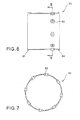
- Fig. 6 is an exemplary side view of one variation of the inner heat shield 60
- Fig. 7 is the section taken along ling VII-VII in Fig. 6
- the inner heat shield 60 is provided integrally with the guide tubes 50. According to this variation, the number of the parts or members can be further reduced, thereby significantly simplifying the structure of the apparatus and adequately controlling the man-hour for assembly and production cost.
Landscapes
- Engineering & Computer Science (AREA)
- Chemical & Material Sciences (AREA)
- Combustion & Propulsion (AREA)
- Mechanical Engineering (AREA)
- General Engineering & Computer Science (AREA)
- Fuel-Injection Apparatus (AREA)
- Spray-Type Burners (AREA)
- Nozzles (AREA)
Abstract
Description
- The present invention relates to a fuel spray apparatus for a gas turbine engine including a staged fuel Injector composed of two combustion methods, i.e., a diffusion combustion and a lean-mixture combustion.
- In recent years, reduction of harmful substances, such as nitrogen oxide (NOx) and the like, discharged from a gas turbine has been strictly required for environmental protection. Meanwhile, for the gas turbine, especially for an airplane engine, good aptitude relight ability has been required, and thus ability for low-NOx combustion as well as for stabilized combustion has attracted significant attention. Thus, the staged fuel injector composed of a single fuel injector valve incorporating the diffusion combustion system adapted for ensuring the stabilized combustion and the lean-mixture combustion system adapted for substantially reducing the NOx has been prevailed. More specifically, this staged fuel injector includes a pilot fuel supply system and a main fuel supply system, wherein fuel can be supplied from only the pilot fuel supply system or part, upon low power operation, thereby to perform more stabilized combustion under diffusion combustion condition, while the fuel can also be supplied from the main fuel supply system or part, upon high power operation, thereby to further reduce the NOx under lean-mixture combustion.
- During a transition from the high power operation to the low power operation in the gas turbine including such a staged fuel injector, the fuel is supplied from only the pilot fuel supply system, while the supply of the fuel from the main fuel supply system is stopped. In order to prevent coking of the fuel remained in a fuel passage of the main fuel supply system (i.e., in a main fuel passage) due to high temperature air fed from a compressor during this transition, a fuel passage portion corresponding to the main fuel passage is covered with a shroud to provide an air heat insulating space or layer between this fuel passage portion and the shroud, or otherwise a separate fuel circuit for always flowing the fuel therethrough is provided to cool the fuel present in the main fuel passage (e.g.,
JP2007-183094A - However, such supply of the purge air as described above requires a high pressure pump, lines, valves and the like, respectively provided for exclusive use, thus inevitably increasing the number of such parts or members, rendering the entire system more complicated and substantially increasing the weight thereof.
- The present invention was made in light of the above problem, Therefore, it is an object of this invention to provide the fuel spray apparatus for the gas turbine engine, which can successfully prevent the coking, while avoiding undue weight increase and complication of the entire system.
- To attain the above object, the fuel spray apparatus used for the gas turbine engine according to this invention includes: a pilot part configured to spray the fuel used for the diffusion combustion; a main part provided so as to surround the pilot part and configured to inject a pre-mixed gas only upon a high power operation; and a shield body constituting a purge air passage configured to take therein an air flowed on the upstream side relative to a fuel injection port of the main part as purge air, and to blow off a fuel dripping (i.e., a dripping of the liquid fuel) from the fuel injection port toward a main air passage of the main part, wherein the purge air passage is provided in a position opposite to the main fuel passage communicated with the fuel Injection port, across the shield body.
- With this configuration, when the supply of the main fuel to the main fuel passage is stopped upon or during the transition from the high power operation to the low power operation, the fuel drippings leaked from the fuel injection port can be blown off toward the main air passage with the purge air, Therefore, the coking caused by such fuel leak can be effectively suppressed. Further, since the air is taken as the purge air into the purge air passage on the downstream side relative to the fuel injection port, there is no need for separately providing equipment exclusively used for taking in or introducing such purge air. Thus, the number of the parts or members to be employed in the apparatus can be substantially reduced, leading to significant reduction of the weight of the apparatus as well as simplification of the structure thereof. Further, since the main fuel passage is heat-insulated from the purge air passage by the shield body, the coking of the fuel in the main fuel passage can be successfully avoided, even though the purge air heated at a relatively high temperature is flowed through the purge air passage.
- In this invention, it is preferred that the fuel spray apparatus for the gas turbine engine further includes a shroud covering the main fuel passage and the shield body, wherein the shroud is provided with an intake port and a discharge port for the purge air, and wherein the purge air passage is provided between an inner face of an outer circumferential wall of the shroud and the shield body, With this configuration, the purge air passage can be readily provided between the inner face of the outer circumferential wall of the shroud and the shield body.
- Further, it is preferred that a passage area of the intake port for the purge air is greater than a passage area of the discharge port. With this configuration, the flow speed of the purge air in the purge air passage can be adequately increased, thereby effectively blowing off the leaked fuel.
- More preferably, the fuel spray apparatus for the gas turbine engine further includes a guide tube provided downstream of the fuel injection port of the main part, such that the fuel dripping can be blown off from the guide tube by the purge air. With this configuration, the fuel can be smoothly introduced from the fuel injection port, due to the guide tube, upon the high power operation, without being leaked into the surrounding parts or members.
- In this invention, it is preferred that the guide tube is located at an outer circumference of an annular downstream part of the main fuel passage, wherein the shield body has a spring elasticity whereby the guide tube can be pressed with a spring force against the outer circumferential face of the main fuel passage. With this configuration, the guide tube can be adequately pressed with the spring force against the outer circumferential face of the main fuel passage. Therefore, there is no need for separately providing any support member for supporting the guide tube. As such, the number of the parts and/or members to be incorporated In the apparatus can be substantially reduced, thereby significantly reducing the apparatus weight and simplifying the structure of the apparatus.
- More preferably, a pilot fuel passage is provided adjacent to the main fuel passage such that a main fuel can be cooled with a pilot fuel. With this configuration, the main fuel can be cooled with the pilot fuel that is always supplied and flowed through the pilot fuel passage. This can eliminate a need for separately providing a proper cooling means, thus significantly reducing the number of parts and/or members to be incorporated In the apparatus.
- According to the fuel spray apparatus for the gas turbine engine of this invention, the fuel drippings leaked from the fuel injection port can be successfully blown off toward the main air passage by the purge air, when the supply of the main fuel to the main fuel passage is stopped, during the transition from the high power operation to the low power operation. Thus, the coking due to the leakage of the fuel can be effectively suppressed. Further, since the air can be taken as the purge air Into the purge air passage on the upstream side relative to the fuel Injection port, there is no need for providing any equipment exclusively used for introducing the purge air. Therefore, the number of parts and/or members to be incorporated In the apparatus can be substantially reduced, thereby significantly reducing the apparatus weight and simplifying the structure of the apparatus. Furthermore, since the main fuel passage can be well heat-insulated by the shield body, the coking of the fuel remained in the main fuel passage can be successfully avoided, even though the purge air heated at a considerably high temperature is flowed through the purge air passage.
-
-
Fig. 1 is a schematic front view showing a combustor of the gas turbine engine including the fuel spray apparatus according to an embodiment of the present invention. -
Fig. 2 is an enlarged section taken along line II-II inFig. 1 . -
Fig. 3 is an enlarged section for Illustrating details of the fuel spray apparatus shown inFig. 2 . -
Fig. 4 is a development elevation of the fuel passages in the fuel spray apparatus shown inFig. 2 . -
Fig. 5 is an enlarged section for illustrating details of a main part of the fuel spray apparatus shown inFig. 2 . -
Fig. 6 is a side view of a variation of an inner heat shield in the fuel spray apparatus shown inFig. 2 . -
Fig. 7 is a section taken along ling VII-VII inFig. 6 . - Hereinafter, one preferred embodiment will be described with reference to the drawings.
-
Fig. 1 shows a head portion of thecombustor 1 of the gas turbine engine including thefuel spray apparatus 2 according to the embodiment of the present invention. Thecombustor 1 can serve to mix the fuel with compressed air supplied from a compressor (not shown) of the gas turbine engine and then combust the fuel with the supplied compressed air in order to drive a turbine by feeding high-temperature and high-pressure combustion gas generated by the combustion into the turbine. - In this
annular type combustor 1, an annularinner casing 8 is concentrically located inside an annularouter casing 7. Theseannular casings combustor housing 6 having an annular internal space provided therein. Further, in this annular internal space of thecombustor housing 6, an annularinner liner 11 is concentrically located inside an annularouter liner 10. Theseannular liners combustion cylinder 9. Thiscombustion cylinder 9 is located concentrically with thecombustor housing 6, and includes anannular combustor chamber 12 provided therein. A plurality of fuel injection units 2 (in this embodiment, fourteen (14) fuel injection units 2), respectively adapted for injecting the fuel into thecombustion chamber 12, are arranged in a top wall 9a of thecombustion cylinder 9, concentrically with thecylinder 9, In a circular line, with an equal interval. Eachfuel injection unit 2 includes a pilot part (or pilot fuel injection nozzle) 3 and a main part (or main fuel injection part) 4 provided to concentrically surround thepilot part 3.Such pilot parts 3 andmain parts 4 will be detailed later. - Two
ignition plugs 13 are respectively extend through theouter casing 7 andouter liner 10, in the radial direction relative to thecombustion cylinder 9, with each distal end of theseplugs 13 positioned in the vicinity of one of thefuel injection units 2. Accordingly, in thiscombustor 1, inflammable or burnable mixed gas injected from the twofuel injection units 2 respectively positioned in the vicinity of the twoignition plugs 13 is first ignited, and the flame generated by such ignition is then transferred to the flammable mixed gas injected from each adjacentfuel injection unit 2 from one after another. In this way, such inflammable mixed gas injected from all of thefuel injection units 2 will be eventually ignited. - Referring to
Fig. 2 , In the annular internal space of thecombustor housing 6, the compressed air CA fed from the compressor is introduced via a plurality ofair intake ducts 14. Then, the so-introduced compressed air CA is supplied to eachfuel injection unit 2, while being supplied into thecombustion chamber 12 via a plurality ofair introducing ports 17, respectively provided in theouter liner 10 andinner liner 11 of thecombustion cylinder 9, Further,fuel piping units 18, each including a first fuel supply system F1 adapted for supplying the fuel used for the diffusion combustion to eachcorresponding pilot part 3 and a second fuel supply system F2 adapted for supplying the fuel used for the lean-mixture combustion to each correspondingmain part 4, are supported by theouter casing 7 and connected with abase part 19 of thecombustion cylinder 9, respectively, Eachfuel injection unit 2 is supported by theouter liner 10, via aflange 5A provided to an outer circumference of thefuel injection unit 2 and asupport member 5B provided to theouter liner 10. Further, theouter liner 10 is supported by theouter casing 7, via astem 16, by means of a liner fixing pin P. A downstream end of thecombustion cylinder 9 is connected with a first-stage nozzle TN of the turbine. - Referring to
Fig. 3 , thepilot part 3 provided at a central portion of each correspondingfuel injection unit 2 includes a cylindricalmain body 20 having a bottom face and adapted for spraying the fuel PF supplied from the first fuel supply system F1 and used for the diffusion combustion, a tubularinner wall 21 externally fitted around themain body 20, a tubularintermediate wall 22 located externally and concentrically relative to the tubularinner wall 21, anozzle body 23 having a venturl-nozzle shape and located externally and concentrically relative to the tubularintermediate wall 22, a first inner swirler 24 located between the tubularinner wall 21 and the tubularintermediate wall 22, and a firstouter swirler 27 located between the tubularintermediate wall 22 and thenozzle body 23. - At a downstream end of the
main body 20, a plurality offuel injection ports 25 are radially provided for respectively injecting the fuel PF supplied into themain body 20, radially outward, Further,fuel introducing ports 26 are provided in the tubularinner wall 21, in positions thereof, respectively corresponding to thefuel Injection ports 25, Each of thefuel introducing ports 26 can serve to introduce the fuel PF into aprimary atomizing passage 28 provided between the tubularinner wall 21 and the tubularintermediate wall 22. In this case, the fuel PF introduced into theprimary atomizing passage 28 is injected from an atomized-fuel injection port 28a located at a downstream end of thepassage 28. - The atomized-
fuel injection port 28a or respective downstream ends of the tubularinner wall 21 and tubularintermediate wall 22 are located in substantially the same position in an axial direction (or lateral direction In the drawing) as the position of a narrowed portion 23a of thenozzle body 23, at which the internal diameter of thenozzle body 23 is minimized, Meanwhile, a diametrically widenedportion 23b of thenozzle body 23 on the downstream side relative to the narrowed portion 23a is formed into an unfolded fan shape, Namely, one portion of thepilot part 3 extending from the upstream end of thepilot part 3 to the narrowed portion 23a of thenozzle body 23 constitutes a fuel atomizing part 3a, and the other portion of thepilot part 3 extending from the narrowed portion 23a to thedownstream end 23c of thenozzle body 23, i.e., the diametrically widenedportion 23b of thenozzle body 23 constitutes adiffusion passage part 3b. Further, in the fuel atomizing part 3a, respectivedownstream portions inner wall 21 and tubularintermediate wall 22 constituting together theprimary atomizing passage 28 are formed into a tapered truncated-cone shape, corresponding to the shape of a point of thenozzle body 23 facing to theseportions primary atomizing passage 28 and firstouter swirler 27, obliquely, toward the central axis of themain body 20 in a layered form. Meanwhile, thediffusion passage part 3b located on the downstream side of the fuel atomizing part 3a can serve to inject the fuel PF and compressed air CA into thecombustion chamber 12, at an Injection angle determined by the diametrically widenedportion 23b, while diffusing the fuel PF with the compressed air CA. - In this
pilot part 3, the fuel PF used for the diffusion combustion is supplied into the fuel atomizing part 3a from the first fuel supply system F1, over all load (or intensity) range of the starting and low power operation (lower than 50% of the full load) as well as the high power operation (higher than 50% of the full load), and subjected to primary atomization with the compressed air CA, in the fuel atomizing part 3a. Subsequently, in thediffusion passage part 3b, the fuel PF is further subjected to secondary atomization with swirling air flow supplied from the firstouter swirler 27. With this secondary atomization, the fuel is changed Into a fog state and sprayed into thecombustion chamber 12, thereby to form a diffusion combustion region PC in thecombustion chamber 12. - Next, the
main part 4 surrounding the outer circumference of eachcorresponding pilot part 3 will be described. Thismain part 4 includes anannular shroud 29 located externally and concentrically with thenozzle body 23, a tubularIntermediate wall 32 located externally and concentrically with theshroud 29, a tubular outercircumferential wall 33 located externally and concentrically with thetubular Intermediate wall 32, acylindrical partition wall 34 provided for partitioning the tubularintermediate wall 32 and the tubular outercircumferential wall 33, a secondinner swirler 38 located at an inlet of a pre-mlxingpreparatory chamber 37 provided between the tubularintermediate wall 32 and thecylindrical partition wall 34, and a secondouter swirler 39 provided between thecylindrical partition wall 34 and the tubular outercircumferential wall 33. Theshroud 29 has a substantially rectangular longitudinal section including the axis thereof, and includes an innercircumferential wall 30 radially facing an outer circumferential face of thenozzle body 23, and an outercircumferential wall 31 radially facing an inner circumferential face of the tubularintermediate wall 32. Further, theshroud 29 is connected with thestem 16. - In the
stem 16 andrectangular shroud 29, thefuel passage 40 is stored, while being attached to thefuel piping unit 18, with a space provided between thefuel passage 40 and theshroud 29. Namely, theshroud 29 covers thefuel passage 40, via the heat insulating space S provided for serving as an air heat insulating layer. - As shown in
Fig. 4 , in thefuel passage 40, apilot fuel passage 44 connected with the first fuel supply system F1 and amain fuel passage 45 connected with the second fuel supply system F2 are provided, respectively. Thepilot fuel passage 44 Includes apilot introducing passage 44a linearly extending along the axial direction of thefuel spray apparatus 2, a pilotannular passage 44b located on the downstream side relative to thepilot introducing passage 44a, and alinear return passage 44c extending in parallel with thepilot introducing passage 44a. In this case, the pilotannular passage 44b is connected with thereturn passage 44c, as shown inFig. 4 , while running substantially around thepilot part 3 shown inFig. 3 . Adownstream end 44d of thereturn passage 44c is connected with afuel introducing passage 44e shown inFig. 3 , such that the fuel PF can be supplied to eachfuel Injection port 25 of thepilot part 3 from thefuel introducing passage 44e. - The
main fuel passage 45 includes a mainfuel introducing passage 45a linearly extending along the axial direction of thefuel spray apparatus 2 and a mainannular passage 45b located on the downstream side relative to the mainfuel introducing passage 45a. The mainannular passage 45b is provided to run substantially around themain part 4, as shown inFig. 3 . A plurality of (e.g., eight)fuel injection ports 35 are opened in the middle of the mainannular passage 45b constituting a downstream part of themain fuel passage 45. Thepilot introducing passage 44a and mainfuel introducing passage 45a, and the pilotannular passage 44b and mainannular passage 45b are respectively positioned close to each other. With this configuration, upon the low power operation, i.e., when the supply of the main fuel MF is stopped, the main fuel MF remained in themain fuel passage 45 can be cooled with pilot fuel PF flowed through the pilotannular passage 44b. - Now, returning to
Fig, 3 , thefuel injection ports 35 are respectively formed in themain part 4 circumferentially and radially relative to themain part 4 with an equal interval. An outlet or radially outward end of eachfuel injection port 35 is connected with aguide tube 50. Thisguide tube 50 constitutes a passage extending in the radial direction. Further, an outlet or radially outward end of eachguide tube 50 is communicated with anoutlet 41 provided in the outercircumferential wall 31 of theshroud 29. In the tubularintermediate wall 32,fuel introducing ports 52 are provided for introducing the fuel MF injected from eachguide tube 50 into the pre-mixingpreparatory chamber 37, respectively. With this configuration, the fuel MF injected from eachfuel injection port 35 can be guided into the pre-mixingpreparatory chamber 37 through eachcorresponding guide tube 50,outlet 41 andfuel introducing port 52. The means for fixing or supporting eachguide tube 50 will be described later, - The
tubular Intermediate wall 32 is provided to cover about half a downstream part of the outercircumferential wall 31 of theshroud 29. A downstream end 32c of the tubularintermediate wall 32 is axially positioned to be projected downstream relative to thedownstream end 23c of thenozzle body 23 of thepilot part 3, while constituting apre-mixing chamber 42 provided between such a downstream end 32c and the tubular outercircumferential wall 33. Between thedownstream end 23c of thenozzle body 23 and the downstream end 32c of thetubular Intermediate wall 32, aseparator 54 for separating the diffusion combustion region PC to be created in thepilot part 3 from a pre-mixing combustion region MC is located. - The position of the upstream end of the
cylindrical partition wall 34 is axially coincident with the upstream end of the tubularintermediate wall 32, while the axial length of thecylindrical partition wall 34 is set, such that thedownstream end 34c of thewall 34 is positioned on the downstream side by a predetermined distance relative to eachfuel introducing port 52. The upstream end of the tubular outercircumferential wall 33 is axially positioned downstream relative to the upstream end of thecylindrical partition wall 34, while the position of the downstream end 33c of thiswall 33 is substantially coincident In the axial direction with the downstream end 32c of the tubularintermediate wall 32. - An
inner heat shield 60 constituting an annular shield body is located between the inner face of the outercircumferential wall 31 of theshroud 29 and an outer circumferential face of thefuel passage 40. Further, apurge air passage 70 is provided between theinner heat shield 60 and the outercircumferential wall 31 of theshroud 29. Namely, thefuel passage 40 Incorporating themain fuel passage 45 and theinner heat shield 60 are covered with theshroud 29, while thepurge air passage 70 is located inside theshroud 29 in a position opposite to themain fuel passage 45 across theinner heat shield 60. - As shown in
Fig. 5 in more detail, theinner heat shield 60 has a cylindricalmain body 61 having twoprojections inner heat shield 60 has a through-hole 66 provided for allowing theguide tube 50 to extend therethrough in a position corresponding to thefuel injection hole 35. In this case, theinner heat shield 60 is formed from a metal, such as spring steel or the like, having suitable spring elasticity. However, it is noted that the material used for forming theinner heat shield 60 is not limited to such a metal. Namely, this material can be optionally selected, depending on the environmental conditions, such as, the temperature or the like, under which theinner heat shield 60 is used. In any case, however, thisinner heat shield 60 can serve to firmly press aflange 51 provided at an upstream end of theguide tube 50 against an outer circumferential face of thefuel passage 40 by the spring elastic force thereof, with theprojections 62 of theshield 60 respectively contacted with the inner face of the outercircumferential wall 31 of theshroud 29 and a distal end of theguide tube 50 extending through the through-hole 66. In this manner, thepurge air passage 70 is formed between the outercircumferential wall 31 of theshroud 29 and themain body 61 of theinner heat shield 60, with both of the upstream and downstream ends thereof being closed by theprojections 62. - On the upstream side of the outer
circumferential wall 31 of theshroud 29, anair intake port 63 for introducing air into thepurge air passage 70 is provided. Thisair intake port 63 is provided in the same position, in the circumferential direction, as the position of theoutlet 41 provided on the downstream side of the outercircumferential wall 31 of theshroud 29, An annular gap is provided between an inner circumferential face of theoutlet 41 and an outer circumferential face of theguide tube 50 and constitutes adischarge port 64 for discharging the air. Namely, if theguide tube 50 is not provided, the entire body of theoutlet 41 will constitute thedischarge port 64. Theair intake port 63 is positioned on the upstream side relative to the swirier 38 (Fig. 3 ), while thedischarge port 64 is positioned on the downstream side relative to theswirler 38. Each of theair intake port 63 andoutlet 41 is composed of a through-hole having a circular section. The passage area S1 of theair intake port 63 is set to be larger than the passage area S2 of theannular discharge port 64. Preferably, the passage area S1 of theintake port 63 is 1.5 to 3.0 times the passage area S2 of thedischarge port 64. It is noted that the shape of such through-holes is not limited to the circle. For instance, either one or both of these holes may be a polygonal shape. - Only upon the high power operation higher than 50% relative to the full load operation, the fuel MF is supplied to the
main part 4 shown inFig. 2 from the second fuel supply system F2. Subsequently, the fuel MF is fed through the mainfuel introducing passage 45a and mainannular passage 45b respectively shown inFig. 3 , and then injected into the pre-mixingpreparatory chamber 37 after flowed through thefuel injection port 35,guide tube 50,outlet 41 andfuel introducing port 52. Thereafter, the so-injected fuel MF is mixed with the compressed air CA supplied from the secondinner swirler 38, and then such mixed gas is further mixed, in thepre-mixing chamber 42, with the swirled air flow supplied from the secondouter swirler 39. In this way, pre-mixed gas, in which the fuel F and the compressed air CA are well mixed together, can be produced. Thereafter, this pre-mixed gas is supplied into thecombustion chamber 12 shown inFig. 2 and combusted therein, thus creating the pre-mixing combustion region MC (Fig. 2 ). - Upon the low power operation in which the fuel F is not supplied to the
main part 4, the compressed air CA is introduced into the pre-mixingpreparatory chamber 37 andpre-mixing chamber 42 through therespective swirlers swirlers swirler 38. Further, with this pressure difference, as shown InFig. 5 , relatively high-pressure air on the upstream side is first taken In, as the purge air PA, from theair intake port 63 of theshroud 29, then flowed through thepurge air passage 70 between theinner heat shield 60 and theshroud 29, thereafter flowed into the respectivemain air passages Fig. 3 from theoutlet 41 of theshroud 29, and finally supplied into thecombustion chamber 12 together with the compressed air CA flowed through therespective swirlers - An
air accumulation chamber 49 is provided between thenozzle body 23 of thepilot part 3 and the tubularintermediate wall 32, and anair inlet port 46 of theseparator 54 is communicated with theair accumulation chamber 49. With this configuration, the compressed air CA accumulated in theair accumulation chamber 49 can be injected toward a boundary between the diffusion combustion region PC and the pre-mixing combustion region MC via theair inlet port 46, thereby enhancing and ensuring separation between the two combustion regions PC and MC. - With the above configuration, upon the starting and low power operation of the
combustor 1, the fuel PF is supplied to only thepilot part 3 located inside thefuel spray apparatus 2 from the first fuel supply system F1. Then, the fuel PF is injected Into thecombustion chamber 12, while being diffused and spread together with the compressed air CA by the unfolded-fan-sha peddiffusion passage part 3b of thepilot part 3. This can facilitate and stabilize the combustion of the fuel in the diffusion combustion region PC. Meanwhile, upon the high power operation, the pilot fuel PF and main fuel MF are supplied to thepilot part 3 andmain part 4, respectively. In themain part 4, as shown inFig. 5 , theguide tube 50 is provided on the downstream side relative to thefuel Injection port 35. Therefore, the main fuel MF can be injected smoothly into the pre-heatingpreparatory chamber 37, through theguide tube 50, without being leaked into the air heat insulating layer S, - However, when the supply of the main fuel MF to the
main part 4 is stopped during the transition from the high power operation to the low power operation, the main fuel MF tends to be leaked because of the air entering themain fuel passage 45 after flowed through thefuel injection port 35 and theguide tube 50. Further, such leakage of the main fuel MF tends to generate fuel drippings (i.e., drippings of the liquid fuel) LF on an Inner wall of the outercircumferential wall 31 of theshroud 29. Thus, such fuel drippings LF may tend to be carbonized (or changed into the coking) by the surrounding high temperature environment. In particular, in eachfuel injection port 35 located at an upper portion of themain part 4, the fuel drippings LF are likely to enter thepurge air passage 70 due to the gravitation (note:Fig. 5 shows onefuel injection port 35 located at a lower portion of the main part 4). In this embodiment, however, even such fuel drippings LF having some tendency to enter thepurge air passage 70 can be blown off toward themain air passages 37, 42 (seeFig, 3 ), due to the purge air PA, Therefore, the coking that may be otherwise caused by such fuel drippings LF can be successfully prevented. Meanwhile, if some coking (or carbonized fuel) LF1 of the fuel drippings LF is accumulated in thepurge air passage 70, such coking LF1 would bring the inner face of the outercircumferential wall 31 of theshroud 29 into contact with theinner heat shield 60, thus unduly rising the temperature of thefuel passage 40 due to the high temperature purge air PA flowed through thepurge air passage 70, This phenomenon would lead to further coking of the main fuel MF stopped in the mainannular passage 45b, However, in this embodiment, with the configuration for positively removing the fuel drippings LF as described above, such unwanted occurrence or generation of the coking can be securely prevented. - Since the air can be taken, as the purge air PA, into the
purge air passage 70 on the upstream side relative to thefuel injection port 35, there is no need to prepare separate equipment exclusively used for the introduction of such purge air PA. Therefore, undue increase of the number of parts or members incorporated in this apparatus can be well controlled, thus substantially reducing the weight of the apparatus and simplifying the structure thereof. Further, the provision of theInner heat shield 60 can adequately insulate themain fuel passage 45 from the environmental heat. Therefore, even though the high temperature purge air PA is used, the occurrence of the coking of the fuel MF remained in themain fuel passage 45 can be successfully prevented. - In addition, the arrangement of the
intake port 63 anddischarge port 64 for the purge air PA to theshroud 29 covering themain fuel passage 45 andInner heat shield 60 as well as the positioning of thepurge air passage 70 between the inner face of the outercircumferential wall 31 of theshroud 29 and theinner heat shield 60 can facilitate the provision of such apurge air passage 70 between the inner face of the outercircumferential wall 31 of theshroud 29 and theinner heat shield 60. - Further, since the passage area S1 of the
intake port 63 for the purge air PA is set to be greater than the passage area S2 of thedischarge port 64, the flow speed of the purge air PA in thepurge air passage 70 can be substantially increased, thus securely enabling the fuel drippings LF to be effectively blown off. - Since the
guide tube 50 can be firmly pressed against the outer circumferential face of themain fuel passage 45 with the spring biasing force or elasticity of the inner heat shied 60, there Is no need for separately providing a proper support member for supporting theguide tube 50, Therefore, the number of the parts or members used In the apparatus can be further reduced, thus significantly reducing the weight and simplifying the structure of the apparatus. - Further, since the main fuel MF can be cooled with the pilot fuel PF that is always supplied in the
fuel passage 40, there is no need for providing a separate cooling means, thereby further controlling the increase of the number of the parts or members to be incorporated in the apparatus. - In order to evaluate an actual effect of this invention, existence of the fuel drippings LF of the main fuel MF upon the stop operation of the fuel supply to the
main part 4 has been inspected with eyes, while the fuel is supplied to both of thepilot part 3 andmain part 4. - As a result, in a comparative model in which the purge air PA is not introduced into the
shroud 29, the fuel drippings LF was found in the shroud after the fuel supply to themain part 4 was stopped. Meanwhile, in a model according to the above embodiment, the fuel drippings LF were securely blown off by the purge air PA, as such the existence of the fuel drippings were not found. -
Fig. 6 is an exemplary side view of one variation of theinner heat shield 60, andFig. 7 is the section taken along ling VII-VII inFig. 6 . In this variation, theinner heat shield 60 is provided integrally with theguide tubes 50. According to this variation, the number of the parts or members can be further reduced, thereby significantly simplifying the structure of the apparatus and adequately controlling the man-hour for assembly and production cost. - As stated above, the preferred embodiment has been described with reference to the drawings. However, it should be understood that various additions, modifications and deletions can be made to this embodiment, without departing from the scope and spirit of the invention. Therefore, it should be construed that such additions, modifications and deletions also fall within the scope of this invention.
Claims (6)
- A fuel spray apparatus for a gas turbine engine, comprising:a pilot part configured to spray fuel to be used for a diffusion combustion;a main part provided so as to surround the pilot part and configured to Inject a pre-mixed gas only upon a high power operation; anda shield body constituting a purge air passage which is configured to take therein an air flowed on an upstream side relative to a fuel injection port of the main part as a purge air, and to blow off a fuel dripping from the fuel injection port toward a main air passage of the main part,wherein the purge air passage is provided in a position opposite to a main fuel passage communicated with the fuel injection port across the shield body.
- The fuel spray apparatus for the gas turbine engine according to claim 1, further comprising a shroud covering the main fuel passage and the shield body, wherein the shroud is provided with an intake port and a discharge port for the purge air, and wherein the purge air passage is provided between an inner face of an outer circumferential wall of the shroud and the shield body,
- The fuel spray apparatus for the gas turbine engine according to claim 2, wherein a passage area of the intake port for the purge air is greater than a passage area of the discharge port.
- The fuel spray apparatus for the gas turbine engine according to any one of claims 1 to 3, further comprising a guide tube provided downstream of the fuel injection port of the main part, such that the fuel dripping can be blown off from the guide tube by the purge air.
- The fuel spray apparatus for the gas turbine engine according to claim 4, wherein the guide tube is located at an outer circumference of an annular downstream part of the main fuel passage, and wherein the shield body has a spring elasticity whereby the guide tube can be pressed with a spring force against an outer circumferential face of the main fuel passage.
- The fuel spray apparatus for the gas turbine engine according to any one of claims 1 to 5, wherein a pilot fuel passage is provided adjacent to the main fuel passage such that a main fuel can be cooled with a pilot fuel.
Applications Claiming Priority (1)
| Application Number | Priority Date | Filing Date | Title |
|---|---|---|---|
| JP2009107440A JP4733195B2 (en) | 2009-04-27 | 2009-04-27 | Fuel spray system for gas turbine engine |
Publications (3)
| Publication Number | Publication Date |
|---|---|
| EP2246628A2 true EP2246628A2 (en) | 2010-11-03 |
| EP2246628A3 EP2246628A3 (en) | 2012-11-21 |
| EP2246628B1 EP2246628B1 (en) | 2017-09-06 |
Family
ID=42395697
Family Applications (1)
| Application Number | Title | Priority Date | Filing Date |
|---|---|---|---|
| EP10160751.3A Active EP2246628B1 (en) | 2009-04-27 | 2010-04-22 | Fuel spray apparatus for gas turbine engine |
Country Status (3)
| Country | Link |
|---|---|
| US (1) | US8935911B2 (en) |
| EP (1) | EP2246628B1 (en) |
| JP (1) | JP4733195B2 (en) |
Cited By (2)
| Publication number | Priority date | Publication date | Assignee | Title |
|---|---|---|---|---|
| EP3184901A4 (en) * | 2014-08-18 | 2018-04-11 | Kawasaki Jukogyo Kabushiki Kaisha | Fuel injecting device |
| EP3184782A4 (en) * | 2014-08-18 | 2018-04-11 | Kawasaki Jukogyo Kabushiki Kaisha | Fuel injection device |
Families Citing this family (33)
| Publication number | Priority date | Publication date | Assignee | Title |
|---|---|---|---|---|
| FR2911667B1 (en) * | 2007-01-23 | 2009-10-02 | Snecma Sa | FUEL INJECTION SYSTEM WITH DOUBLE INJECTOR. |
| US8726668B2 (en) * | 2010-12-17 | 2014-05-20 | General Electric Company | Fuel atomization dual orifice fuel nozzle |
| US9360219B2 (en) | 2010-12-30 | 2016-06-07 | Rolls-Royce North American Technologies, Inc. | Supercritical or mixed phase multi-port fuel injector |
| US8973368B2 (en) | 2011-01-26 | 2015-03-10 | United Technologies Corporation | Mixer assembly for a gas turbine engine |
| US8312724B2 (en) | 2011-01-26 | 2012-11-20 | United Technologies Corporation | Mixer assembly for a gas turbine engine having a pilot mixer with a corner flame stabilizing recirculation zone |
| US9920932B2 (en) | 2011-01-26 | 2018-03-20 | United Technologies Corporation | Mixer assembly for a gas turbine engine |
| US8893500B2 (en) * | 2011-05-18 | 2014-11-25 | Solar Turbines Inc. | Lean direct fuel injector |
| JP5772245B2 (en) * | 2011-06-03 | 2015-09-02 | 川崎重工業株式会社 | Fuel injection device |
| JP5924618B2 (en) * | 2012-06-07 | 2016-05-25 | 川崎重工業株式会社 | Fuel injection device |
| GB201222304D0 (en) | 2012-12-12 | 2013-01-23 | Rolls Royce Plc | A fuel injector and a gas turbine engine combustion chamber |
| WO2014137412A1 (en) * | 2013-03-05 | 2014-09-12 | Rolls-Royce Corporation | Gas turbine engine fuel air mixer |
| US20160040881A1 (en) * | 2013-03-14 | 2016-02-11 | United Technologies Corporation | Gas turbine engine combustor |
| RU2514555C1 (en) * | 2013-04-05 | 2014-04-27 | Владислав Юрьевич Климов | Two-component gas-fluid atomiser |
| GB201315008D0 (en) | 2013-08-22 | 2013-10-02 | Rolls Royce Plc | Airblast fuel injector |
| JP6695801B2 (en) * | 2013-12-23 | 2020-05-20 | ゼネラル・エレクトリック・カンパニイ | Fuel nozzle with flexible support structure |
| CA2933536C (en) * | 2013-12-23 | 2018-06-26 | General Electric Company | Fuel nozzle structure for air-assisted fuel injection |
| JP6410133B2 (en) * | 2014-08-18 | 2018-10-24 | 川崎重工業株式会社 | Fuel injection device |
| JP6440433B2 (en) * | 2014-09-29 | 2018-12-19 | 川崎重工業株式会社 | Fuel injection nozzle, fuel injection module, and gas turbine |
| US9453461B2 (en) * | 2014-12-23 | 2016-09-27 | General Electric Company | Fuel nozzle structure |
| CN104566469B (en) * | 2014-12-30 | 2018-09-14 | 北京华清燃气轮机与煤气化联合循环工程技术有限公司 | A kind of dual fuel nozzle of gas-turbine combustion chamber |
| US9939157B2 (en) * | 2015-03-10 | 2018-04-10 | General Electric Company | Hybrid air blast fuel nozzle |
| US10591164B2 (en) * | 2015-03-12 | 2020-03-17 | General Electric Company | Fuel nozzle for a gas turbine engine |
| US10267524B2 (en) * | 2015-09-16 | 2019-04-23 | Woodward, Inc. | Prefilming fuel/air mixer |
| GB2543803B (en) * | 2015-10-29 | 2019-10-30 | Rolls Royce Plc | A combustion chamber assembly |
| JP6621658B2 (en) * | 2015-12-22 | 2019-12-18 | 川崎重工業株式会社 | Fuel injection device |
| US10724741B2 (en) * | 2016-05-10 | 2020-07-28 | General Electric Company | Combustors and methods of assembling the same |
| US10502425B2 (en) * | 2016-06-03 | 2019-12-10 | General Electric Company | Contoured shroud swirling pre-mix fuel injector assembly |
| US11112117B2 (en) | 2018-07-17 | 2021-09-07 | General Electric Company | Fuel nozzle cooling structure |
| GB201909167D0 (en) * | 2019-06-26 | 2019-08-07 | Rolls Royce Plc | Fuel injector |
| DE102021001587A1 (en) * | 2021-03-25 | 2022-09-29 | Mercedes-Benz Group AG | Method for operating a burner of a motor vehicle |
| US12644604B2 (en) * | 2021-05-21 | 2026-06-02 | General Electric Company | Pilot fuel nozzle assembly with vented venturi |
| US20250257874A1 (en) * | 2024-02-12 | 2025-08-14 | General Electric Company | Pilot fuel nozzle assembly with multi-angled venturi |
| WO2026048395A1 (en) * | 2024-08-30 | 2026-03-05 | 国立研究開発法人宇宙航空研究開発機構 | Fuel injector, combustor, gas turbine, and combustor system |
Citations (1)
| Publication number | Priority date | Publication date | Assignee | Title |
|---|---|---|---|---|
| JP2007183094A (en) | 2006-01-09 | 2007-07-19 | Snecma | Cooling of multimode fuel injectors, especially for jet engine combustion chambers |
Family Cites Families (8)
| Publication number | Priority date | Publication date | Assignee | Title |
|---|---|---|---|---|
| JPH08145362A (en) * | 1994-11-18 | 1996-06-07 | Toyota Central Res & Dev Lab Inc | Perforated two-fluid injection device and spray-type combustion device equipped with the same |
| JPH11324722A (en) * | 1998-05-12 | 1999-11-26 | Mitsubishi Heavy Ind Ltd | Gas turbine fuel nozzle cleaning system |
| US6959535B2 (en) | 2003-01-31 | 2005-11-01 | General Electric Company | Differential pressure induced purging fuel injectors |
| US6898926B2 (en) * | 2003-01-31 | 2005-05-31 | General Electric Company | Cooled purging fuel injectors |
| US6898938B2 (en) | 2003-04-24 | 2005-05-31 | General Electric Company | Differential pressure induced purging fuel injector with asymmetric cyclone |
| US7464553B2 (en) * | 2005-07-25 | 2008-12-16 | General Electric Company | Air-assisted fuel injector for mixer assembly of a gas turbine engine combustor |
| JP2007162998A (en) * | 2005-12-13 | 2007-06-28 | Kawasaki Heavy Ind Ltd | Fuel spray system for gas turbine engine |
| US20100251719A1 (en) * | 2006-12-29 | 2010-10-07 | Alfred Albert Mancini | Centerbody for mixer assembly of a gas turbine engine combustor |
-
2009
- 2009-04-27 JP JP2009107440A patent/JP4733195B2/en active Active
-
2010
- 2010-04-21 US US12/662,521 patent/US8935911B2/en active Active
- 2010-04-22 EP EP10160751.3A patent/EP2246628B1/en active Active
Patent Citations (1)
| Publication number | Priority date | Publication date | Assignee | Title |
|---|---|---|---|---|
| JP2007183094A (en) | 2006-01-09 | 2007-07-19 | Snecma | Cooling of multimode fuel injectors, especially for jet engine combustion chambers |
Cited By (2)
| Publication number | Priority date | Publication date | Assignee | Title |
|---|---|---|---|---|
| EP3184901A4 (en) * | 2014-08-18 | 2018-04-11 | Kawasaki Jukogyo Kabushiki Kaisha | Fuel injecting device |
| EP3184782A4 (en) * | 2014-08-18 | 2018-04-11 | Kawasaki Jukogyo Kabushiki Kaisha | Fuel injection device |
Also Published As
| Publication number | Publication date |
|---|---|
| EP2246628B1 (en) | 2017-09-06 |
| US8935911B2 (en) | 2015-01-20 |
| JP2010255944A (en) | 2010-11-11 |
| EP2246628A3 (en) | 2012-11-21 |
| JP4733195B2 (en) | 2011-07-27 |
| US20100269506A1 (en) | 2010-10-28 |
Similar Documents
| Publication | Publication Date | Title |
|---|---|---|
| EP2246628B1 (en) | Fuel spray apparatus for gas turbine engine | |
| US8919137B2 (en) | Assemblies and apparatus related to integrating late lean injection into combustion turbine engines | |
| US8407892B2 (en) | Methods relating to integrating late lean injection into combustion turbine engines | |
| US9010120B2 (en) | Assemblies and apparatus related to integrating late lean injection into combustion turbine engines | |
| EP1959196B1 (en) | Combustor of a gas turbine | |
| US7617684B2 (en) | Impingement cooled can combustor | |
| US6959551B2 (en) | Aeromechanical injection system with a primary anti-return swirler | |
| CN104334972B (en) | Fuel injection device | |
| US20080289340A1 (en) | Combustor of a gas turbine engine | |
| US20120227373A1 (en) | Combustion chamber having a ventilated spark plug | |
| US10228140B2 (en) | Gas-only cartridge for a premix fuel nozzle | |
| JP2012229697A (en) | Method and apparatus for combusting fuel within gas turbine engine | |
| US10697639B2 (en) | Dual-fuel fuel nozzle with liquid fuel tip | |
| US20170363294A1 (en) | Pilot premix nozzle and fuel nozzle assembly | |
| US11002196B2 (en) | Combustion chamber comprising two types of injectors in which the sealing members have a different opening threshold | |
| EP2530383A1 (en) | Gas turbine combustor | |
| CN107940502B (en) | Combustion Dynamic Mitigation System | |
| US10955141B2 (en) | Dual-fuel fuel nozzle with gas and liquid fuel capability | |
| US10663171B2 (en) | Dual-fuel fuel nozzle with gas and liquid fuel capability | |
| US20240263786A1 (en) | Central air passage with radial fuel distributor | |
| US10947902B2 (en) | Fuel nozzle, fuel supply assembly thereof, and method of assembling a fuel nozzle | |
| US10641493B2 (en) | Aerodynamic fastening of turbomachine fuel injectors |
Legal Events
| Date | Code | Title | Description |
|---|---|---|---|
| PUAI | Public reference made under article 153(3) epc to a published international application that has entered the european phase |
Free format text: ORIGINAL CODE: 0009012 |
|
| 17P | Request for examination filed |
Effective date: 20100512 |
|
| AK | Designated contracting states |
Kind code of ref document: A2 Designated state(s): AT BE BG CH CY CZ DE DK EE ES FI FR GB GR HR HU IE IS IT LI LT LU LV MC MK MT NL NO PL PT RO SE SI SK SM TR |
|
| AX | Request for extension of the european patent |
Extension state: AL BA ME RS |
|
| PUAL | Search report despatched |
Free format text: ORIGINAL CODE: 0009013 |
|
| AK | Designated contracting states |
Kind code of ref document: A3 Designated state(s): AT BE BG CH CY CZ DE DK EE ES FI FR GB GR HR HU IE IS IT LI LT LU LV MC MK MT NL NO PL PT RO SE SI SK SM TR |
|
| AX | Request for extension of the european patent |
Extension state: AL BA ME RS |
|
| RIC1 | Information provided on ipc code assigned before grant |
Ipc: F23R 3/50 20060101ALI20121017BHEP Ipc: F23R 3/34 20060101ALI20121017BHEP Ipc: F23D 11/38 20060101ALI20121017BHEP Ipc: F23R 3/28 20060101AFI20121017BHEP Ipc: F23R 3/10 20060101ALI20121017BHEP |
|
| 17Q | First examination report despatched |
Effective date: 20160510 |
|
| GRAP | Despatch of communication of intention to grant a patent |
Free format text: ORIGINAL CODE: EPIDOSNIGR1 |
|
| INTG | Intention to grant announced |
Effective date: 20170323 |
|
| GRAS | Grant fee paid |
Free format text: ORIGINAL CODE: EPIDOSNIGR3 |
|
| GRAA | (expected) grant |
Free format text: ORIGINAL CODE: 0009210 |
|
| AK | Designated contracting states |
Kind code of ref document: B1 Designated state(s): AT BE BG CH CY CZ DE DK EE ES FI FR GB GR HR HU IE IS IT LI LT LU LV MC MK MT NL NO PL PT RO SE SI SK SM TR |
|
| REG | Reference to a national code |
Ref country code: GB Ref legal event code: FG4D |
|
| REG | Reference to a national code |
Ref country code: CH Ref legal event code: EP Ref country code: AT Ref legal event code: REF Ref document number: 926296 Country of ref document: AT Kind code of ref document: T Effective date: 20170915 |
|
| REG | Reference to a national code |
Ref country code: IE Ref legal event code: FG4D |
|
| REG | Reference to a national code |
Ref country code: DE Ref legal event code: R096 Ref document number: 602010044950 Country of ref document: DE |
|
| REG | Reference to a national code |
Ref country code: NL Ref legal event code: MP Effective date: 20170906 |
|
| REG | Reference to a national code |
Ref country code: LT Ref legal event code: MG4D |
|
| PG25 | Lapsed in a contracting state [announced via postgrant information from national office to epo] |
Ref country code: HR Free format text: LAPSE BECAUSE OF FAILURE TO SUBMIT A TRANSLATION OF THE DESCRIPTION OR TO PAY THE FEE WITHIN THE PRESCRIBED TIME-LIMIT Effective date: 20170906 Ref country code: FI Free format text: LAPSE BECAUSE OF FAILURE TO SUBMIT A TRANSLATION OF THE DESCRIPTION OR TO PAY THE FEE WITHIN THE PRESCRIBED TIME-LIMIT Effective date: 20170906 Ref country code: SE Free format text: LAPSE BECAUSE OF FAILURE TO SUBMIT A TRANSLATION OF THE DESCRIPTION OR TO PAY THE FEE WITHIN THE PRESCRIBED TIME-LIMIT Effective date: 20170906 Ref country code: LT Free format text: LAPSE BECAUSE OF FAILURE TO SUBMIT A TRANSLATION OF THE DESCRIPTION OR TO PAY THE FEE WITHIN THE PRESCRIBED TIME-LIMIT Effective date: 20170906 Ref country code: NO Free format text: LAPSE BECAUSE OF FAILURE TO SUBMIT A TRANSLATION OF THE DESCRIPTION OR TO PAY THE FEE WITHIN THE PRESCRIBED TIME-LIMIT Effective date: 20171206 |
|
| REG | Reference to a national code |
Ref country code: AT Ref legal event code: MK05 Ref document number: 926296 Country of ref document: AT Kind code of ref document: T Effective date: 20170906 |
|
| PG25 | Lapsed in a contracting state [announced via postgrant information from national office to epo] |
Ref country code: LV Free format text: LAPSE BECAUSE OF FAILURE TO SUBMIT A TRANSLATION OF THE DESCRIPTION OR TO PAY THE FEE WITHIN THE PRESCRIBED TIME-LIMIT Effective date: 20170906 Ref country code: ES Free format text: LAPSE BECAUSE OF FAILURE TO SUBMIT A TRANSLATION OF THE DESCRIPTION OR TO PAY THE FEE WITHIN THE PRESCRIBED TIME-LIMIT Effective date: 20170906 Ref country code: BG Free format text: LAPSE BECAUSE OF FAILURE TO SUBMIT A TRANSLATION OF THE DESCRIPTION OR TO PAY THE FEE WITHIN THE PRESCRIBED TIME-LIMIT Effective date: 20171206 Ref country code: GR Free format text: LAPSE BECAUSE OF FAILURE TO SUBMIT A TRANSLATION OF THE DESCRIPTION OR TO PAY THE FEE WITHIN THE PRESCRIBED TIME-LIMIT Effective date: 20171207 |
|
| PG25 | Lapsed in a contracting state [announced via postgrant information from national office to epo] |
Ref country code: NL Free format text: LAPSE BECAUSE OF FAILURE TO SUBMIT A TRANSLATION OF THE DESCRIPTION OR TO PAY THE FEE WITHIN THE PRESCRIBED TIME-LIMIT Effective date: 20170906 |
|
| REG | Reference to a national code |
Ref country code: FR Ref legal event code: PLFP Year of fee payment: 9 |
|
| PG25 | Lapsed in a contracting state [announced via postgrant information from national office to epo] |
Ref country code: RO Free format text: LAPSE BECAUSE OF FAILURE TO SUBMIT A TRANSLATION OF THE DESCRIPTION OR TO PAY THE FEE WITHIN THE PRESCRIBED TIME-LIMIT Effective date: 20170906 Ref country code: PL Free format text: LAPSE BECAUSE OF FAILURE TO SUBMIT A TRANSLATION OF THE DESCRIPTION OR TO PAY THE FEE WITHIN THE PRESCRIBED TIME-LIMIT Effective date: 20170906 Ref country code: CZ Free format text: LAPSE BECAUSE OF FAILURE TO SUBMIT A TRANSLATION OF THE DESCRIPTION OR TO PAY THE FEE WITHIN THE PRESCRIBED TIME-LIMIT Effective date: 20170906 |
|
| PG25 | Lapsed in a contracting state [announced via postgrant information from national office to epo] |
Ref country code: SK Free format text: LAPSE BECAUSE OF FAILURE TO SUBMIT A TRANSLATION OF THE DESCRIPTION OR TO PAY THE FEE WITHIN THE PRESCRIBED TIME-LIMIT Effective date: 20170906 Ref country code: EE Free format text: LAPSE BECAUSE OF FAILURE TO SUBMIT A TRANSLATION OF THE DESCRIPTION OR TO PAY THE FEE WITHIN THE PRESCRIBED TIME-LIMIT Effective date: 20170906 Ref country code: SM Free format text: LAPSE BECAUSE OF FAILURE TO SUBMIT A TRANSLATION OF THE DESCRIPTION OR TO PAY THE FEE WITHIN THE PRESCRIBED TIME-LIMIT Effective date: 20170906 Ref country code: AT Free format text: LAPSE BECAUSE OF FAILURE TO SUBMIT A TRANSLATION OF THE DESCRIPTION OR TO PAY THE FEE WITHIN THE PRESCRIBED TIME-LIMIT Effective date: 20170906 Ref country code: IT Free format text: LAPSE BECAUSE OF FAILURE TO SUBMIT A TRANSLATION OF THE DESCRIPTION OR TO PAY THE FEE WITHIN THE PRESCRIBED TIME-LIMIT Effective date: 20170906 Ref country code: IS Free format text: LAPSE BECAUSE OF FAILURE TO SUBMIT A TRANSLATION OF THE DESCRIPTION OR TO PAY THE FEE WITHIN THE PRESCRIBED TIME-LIMIT Effective date: 20180106 |
|
| REG | Reference to a national code |
Ref country code: DE Ref legal event code: R097 Ref document number: 602010044950 Country of ref document: DE |
|
| PLBE | No opposition filed within time limit |
Free format text: ORIGINAL CODE: 0009261 |
|
| STAA | Information on the status of an ep patent application or granted ep patent |
Free format text: STATUS: NO OPPOSITION FILED WITHIN TIME LIMIT |
|
| PG25 | Lapsed in a contracting state [announced via postgrant information from national office to epo] |
Ref country code: DK Free format text: LAPSE BECAUSE OF FAILURE TO SUBMIT A TRANSLATION OF THE DESCRIPTION OR TO PAY THE FEE WITHIN THE PRESCRIBED TIME-LIMIT Effective date: 20170906 |
|
| 26N | No opposition filed |
Effective date: 20180607 |
|
| PG25 | Lapsed in a contracting state [announced via postgrant information from national office to epo] |
Ref country code: SI Free format text: LAPSE BECAUSE OF FAILURE TO SUBMIT A TRANSLATION OF THE DESCRIPTION OR TO PAY THE FEE WITHIN THE PRESCRIBED TIME-LIMIT Effective date: 20170906 |
|
| PG25 | Lapsed in a contracting state [announced via postgrant information from national office to epo] |
Ref country code: MC Free format text: LAPSE BECAUSE OF FAILURE TO SUBMIT A TRANSLATION OF THE DESCRIPTION OR TO PAY THE FEE WITHIN THE PRESCRIBED TIME-LIMIT Effective date: 20170906 |
|
| REG | Reference to a national code |
Ref country code: CH Ref legal event code: PL |
|
| REG | Reference to a national code |
Ref country code: BE Ref legal event code: MM Effective date: 20180430 |
|
| REG | Reference to a national code |
Ref country code: IE Ref legal event code: MM4A |
|
| PG25 | Lapsed in a contracting state [announced via postgrant information from national office to epo] |
Ref country code: LU Free format text: LAPSE BECAUSE OF NON-PAYMENT OF DUE FEES Effective date: 20180422 |
|
| PG25 | Lapsed in a contracting state [announced via postgrant information from national office to epo] |
Ref country code: LI Free format text: LAPSE BECAUSE OF NON-PAYMENT OF DUE FEES Effective date: 20180430 Ref country code: CH Free format text: LAPSE BECAUSE OF NON-PAYMENT OF DUE FEES Effective date: 20180430 Ref country code: BE Free format text: LAPSE BECAUSE OF NON-PAYMENT OF DUE FEES Effective date: 20180430 |
|
| PG25 | Lapsed in a contracting state [announced via postgrant information from national office to epo] |
Ref country code: IE Free format text: LAPSE BECAUSE OF NON-PAYMENT OF DUE FEES Effective date: 20180422 |
|
| PG25 | Lapsed in a contracting state [announced via postgrant information from national office to epo] |
Ref country code: MT Free format text: LAPSE BECAUSE OF NON-PAYMENT OF DUE FEES Effective date: 20180422 |
|
| PG25 | Lapsed in a contracting state [announced via postgrant information from national office to epo] |
Ref country code: TR Free format text: LAPSE BECAUSE OF FAILURE TO SUBMIT A TRANSLATION OF THE DESCRIPTION OR TO PAY THE FEE WITHIN THE PRESCRIBED TIME-LIMIT Effective date: 20170906 |
|
| PG25 | Lapsed in a contracting state [announced via postgrant information from national office to epo] |
Ref country code: PT Free format text: LAPSE BECAUSE OF FAILURE TO SUBMIT A TRANSLATION OF THE DESCRIPTION OR TO PAY THE FEE WITHIN THE PRESCRIBED TIME-LIMIT Effective date: 20170906 Ref country code: HU Free format text: LAPSE BECAUSE OF FAILURE TO SUBMIT A TRANSLATION OF THE DESCRIPTION OR TO PAY THE FEE WITHIN THE PRESCRIBED TIME-LIMIT; INVALID AB INITIO Effective date: 20100422 |
|
| PG25 | Lapsed in a contracting state [announced via postgrant information from national office to epo] |
Ref country code: CY Free format text: LAPSE BECAUSE OF FAILURE TO SUBMIT A TRANSLATION OF THE DESCRIPTION OR TO PAY THE FEE WITHIN THE PRESCRIBED TIME-LIMIT Effective date: 20170906 Ref country code: MK Free format text: LAPSE BECAUSE OF NON-PAYMENT OF DUE FEES Effective date: 20170906 |
|
| PGFP | Annual fee paid to national office [announced via postgrant information from national office to epo] |
Ref country code: GB Payment date: 20260313 Year of fee payment: 17 |
|
| PGFP | Annual fee paid to national office [announced via postgrant information from national office to epo] |
Ref country code: FR Payment date: 20260309 Year of fee payment: 17 |
|
| PGFP | Annual fee paid to national office [announced via postgrant information from national office to epo] |
Ref country code: DE Payment date: 20260305 Year of fee payment: 17 |