EP2246579A1 - Seal for knuckle couplings and use thereof - Google Patents
Seal for knuckle couplings and use thereof Download PDFInfo
- Publication number
- EP2246579A1 EP2246579A1 EP08871998A EP08871998A EP2246579A1 EP 2246579 A1 EP2246579 A1 EP 2246579A1 EP 08871998 A EP08871998 A EP 08871998A EP 08871998 A EP08871998 A EP 08871998A EP 2246579 A1 EP2246579 A1 EP 2246579A1
- Authority
- EP
- European Patent Office
- Prior art keywords
- ball
- sealing
- fixed part
- socket joints
- brush
- Prior art date
- Legal status (The legal status is an assumption and is not a legal conclusion. Google has not performed a legal analysis and makes no representation as to the accuracy of the status listed.)
- Withdrawn
Links
Images
Classifications
-
- F—MECHANICAL ENGINEERING; LIGHTING; HEATING; WEAPONS; BLASTING
- F16—ENGINEERING ELEMENTS AND UNITS; GENERAL MEASURES FOR PRODUCING AND MAINTAINING EFFECTIVE FUNCTIONING OF MACHINES OR INSTALLATIONS; THERMAL INSULATION IN GENERAL
- F16J—PISTONS; CYLINDERS; SEALINGS
- F16J15/00—Sealings
- F16J15/16—Sealings between relatively-moving surfaces
- F16J15/32—Sealings between relatively-moving surfaces with elastic sealings, e.g. O-rings
- F16J15/3284—Sealings between relatively-moving surfaces with elastic sealings, e.g. O-rings characterised by their structure; Selection of materials
- F16J15/3288—Filamentary structures, e.g. brush seals
-
- F—MECHANICAL ENGINEERING; LIGHTING; HEATING; WEAPONS; BLASTING
- F16—ENGINEERING ELEMENTS AND UNITS; GENERAL MEASURES FOR PRODUCING AND MAINTAINING EFFECTIVE FUNCTIONING OF MACHINES OR INSTALLATIONS; THERMAL INSULATION IN GENERAL
- F16C—SHAFTS; FLEXIBLE SHAFTS; ELEMENTS OR CRANKSHAFT MECHANISMS; ROTARY BODIES OTHER THAN GEARING ELEMENTS; BEARINGS
- F16C11/00—Pivots; Pivotal connections
- F16C11/04—Pivotal connections
- F16C11/06—Ball-joints; Other joints having more than one degree of angular freedom, i.e. universal joints
-
- F—MECHANICAL ENGINEERING; LIGHTING; HEATING; WEAPONS; BLASTING
- F16—ENGINEERING ELEMENTS AND UNITS; GENERAL MEASURES FOR PRODUCING AND MAINTAINING EFFECTIVE FUNCTIONING OF MACHINES OR INSTALLATIONS; THERMAL INSULATION IN GENERAL
- F16C—SHAFTS; FLEXIBLE SHAFTS; ELEMENTS OR CRANKSHAFT MECHANISMS; ROTARY BODIES OTHER THAN GEARING ELEMENTS; BEARINGS
- F16C11/00—Pivots; Pivotal connections
- F16C11/04—Pivotal connections
- F16C11/06—Ball-joints; Other joints having more than one degree of angular freedom, i.e. universal joints
- F16C11/0666—Sealing means between the socket and the inner member shaft
- F16C11/0676—Sealing means between the socket and the inner member shaft allowing operational relative movement of joint parts due to sliding between parts of the sealing means
-
- F—MECHANICAL ENGINEERING; LIGHTING; HEATING; WEAPONS; BLASTING
- F16—ENGINEERING ELEMENTS AND UNITS; GENERAL MEASURES FOR PRODUCING AND MAINTAINING EFFECTIVE FUNCTIONING OF MACHINES OR INSTALLATIONS; THERMAL INSULATION IN GENERAL
- F16C—SHAFTS; FLEXIBLE SHAFTS; ELEMENTS OR CRANKSHAFT MECHANISMS; ROTARY BODIES OTHER THAN GEARING ELEMENTS; BEARINGS
- F16C23/00—Bearings for exclusively rotary movement adjustable for aligning or positioning
- F16C23/02—Sliding-contact bearings
- F16C23/04—Sliding-contact bearings self-adjusting
-
- F—MECHANICAL ENGINEERING; LIGHTING; HEATING; WEAPONS; BLASTING
- F16—ENGINEERING ELEMENTS AND UNITS; GENERAL MEASURES FOR PRODUCING AND MAINTAINING EFFECTIVE FUNCTIONING OF MACHINES OR INSTALLATIONS; THERMAL INSULATION IN GENERAL
- F16C—SHAFTS; FLEXIBLE SHAFTS; ELEMENTS OR CRANKSHAFT MECHANISMS; ROTARY BODIES OTHER THAN GEARING ELEMENTS; BEARINGS
- F16C33/00—Parts of bearings; Special methods for making bearings or parts thereof
- F16C33/72—Sealings
- F16C33/74—Sealings of sliding-contact bearings
-
- F—MECHANICAL ENGINEERING; LIGHTING; HEATING; WEAPONS; BLASTING
- F16—ENGINEERING ELEMENTS AND UNITS; GENERAL MEASURES FOR PRODUCING AND MAINTAINING EFFECTIVE FUNCTIONING OF MACHINES OR INSTALLATIONS; THERMAL INSULATION IN GENERAL
- F16J—PISTONS; CYLINDERS; SEALINGS
- F16J15/00—Sealings
- F16J15/16—Sealings between relatively-moving surfaces
- F16J15/32—Sealings between relatively-moving surfaces with elastic sealings, e.g. O-rings
Definitions
- the present invention relates to providing a sealing intended to cover grooves, slots and/or gaps that are variable in both shape and size, in ball-and-socket joints for vehicles such as aircraft, cars, trains, etc.
- the present invention is framed within the field of seals intended to cover grooves, slots and/or gaps that are variable in both shape and size, in ball-and-socket joints for vehicles such as aircraft, cars, trains and similar.
- Present-day metallic seals are, given their nature, welded to the body of the fixed part, with the fixed part being anchored to the structure on which the ball-and-socket joint is fitted during the manufacturing process.
- the solution for giving the sealing system back its functionality includes dismantling and discarding the swivel, and then fitting a new swivel in the fixed part. This solution is, therefore, extremely costly in terms of time and money.
- the prior art includes ball-and-socket joint ASNA2557E, which has a seal that includes an elastic made of silicone, though the protective shield preventing the entry of contaminating agents continues to be metallic and not much flexible.
- the present invention is designed to overcome the drawbacks of the sealing mechanisms of the present art.
- typical zones for application of the present invention would be areas housing numerous systems and mechanisms with external lubrication, such as for example the bays of the landing gear of an aircraft.
- the present invention is related to a sealing for ball-and-socket joints, where the ball-and-socket joint is defined by the join between a swivel sphere with a fixed part, said fixed part being attached to a structure on which the ball-and-socket joint is fitted, and which consists of a frame, arranged around the circumference where the swivel sphere is joined to the fixed part with the structure on which it is mounted.
- the inside of the frame contains a set of hairs or threads that altogether give it the appearance of a brush.
- This brush performs the function of preventing foreign agents from penetrating inside the swivel and on the contact surface, during the movement of the ball-and-socket joint, in other words, the movement between the sphere of the swivel and the fixed part with the structure on which it is fitted.
- this brush permits the ball-and-socket joint to meet the maximum angular deviation stated in the specification for the swivel, without losing its properties under special functioning conditions, this is, in the presence of contaminating agents, due to high mechanical stress, nor on account of abrupt changes in pressure and temperature Inherent to the aircraft.
- the type of material that is desirable for the hairs or threads of the brush can be either natural or synthetic (for example nylon), indifferently, depending on the compatibility that is needed with the outside agents.
- This compatibility refers to its chemical resistance towards contaminating agents, given the fact that these could, for example, be corrosive or they could attack plastic elements.
- the length of the hairs or threads lies within the interval of 5 to 10 mm and the diameter between 0.2 and 0.8 mm.
- the type of material desirable for the frame is preferably flexible, and can be synthetic, such as for example fluoropolymer (Teflon ® ). It can also be a non-flexible frame, as might be a metallic frame.
- the frame and the brush have a high degree of flexibility.
- the brush is based on one of the already standardized brushes of the type ASNA-2169. CAN36007 or DAN136, adapted for this application, meaning, with the hairs or threads shorter, the frame smaller and in the form of a circumference.
- Another advantage of this type of sealing is that it complies with what is stated in the previous paragraph without losing resistance under the special and adverse conditions to which it has to be subjected, such as abrupt changes of pressure and temperature and high mechanical stress.
- this system of sealing allows the fixed part to be adhered to the structure on which it is mounted, using an adhesive of the type that sets at ambient temperature or with the local application of heat, and therefore the adhesion is easily replaceable, meaning that the seal is able to be replaced in the event of suffering any damage or defect without the need to dismantle the ball-and-socket joint from the structure on which it is mounted.
- the present invention describes the use of the sealing described above In grooves, slots or gaps, In grooves, slots or gaps of a vehicle, in grooves, slots or gaps of an aircraft and in structural joints that are subjected to severe ambient conditions at wide pressure and temperature intervals, for example in cycles from 70° C to -54° C, in very short time intervals, this is minutes.
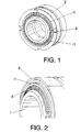
- FIGS. 1 and 2 show a diagram of the sealing fitted in the ball-and-socket joint, where the ball-and-socket joint is defined by the join between a swivel sphere (1) with a fixed part (2), said fixed part (2) being anchored to a structure on which the ball-and-socket joint is fitted.
- Said seal comprises a frame (4), arranged around the circumference where the swivel sphere (1) is joined to the fixed part (2), and a brush (3).
- the brush (3) preferably comprises a set of hairs or threads of a material that is natural or synthetic and flexible
- the frame (4) is preferably made of a material that is synthetic and flexible.
- the frame (4) and the brush (3) are stuck to the fixed part (2) with an adhesive, preferably the adhesive is of the type that sets with the local application of heat.
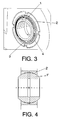
- Figure 3 shows a diagram of the seal of the ball-and-socket joint already fixed to the structure.
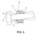
- Figure 4 shows a diagram of a rigid seal existing in the prior art, where the reference 1' corresponds to the swivel and 2' corresponds to the fixed part of the ball-and-socket joint, and figure 5 shows a diagram showing the problem presented by this type of seal, where the reference 3' corresponds to the bolt in the standard position and 3" to the bolt in the rotated position, and in which the zones 4' can be clearly seen as zones of interference, where the breakages previously stated in this specification take place.
- Figures 6.1, 6.2 and 6.3 relate to photos of a real situation of a damaged rigid sealing system, in order to facilitate a visualization of the problem presented by those seals.
Landscapes
- Engineering & Computer Science (AREA)
- General Engineering & Computer Science (AREA)
- Mechanical Engineering (AREA)
- Gasket Seals (AREA)
- Pivots And Pivotal Connections (AREA)
Abstract
Description
- As stated in the title of this specification, the present invention relates to providing a sealing intended to cover grooves, slots and/or gaps that are variable in both shape and size, in ball-and-socket joints for vehicles such as aircraft, cars, trains, etc.
- The present invention is framed within the field of seals intended to cover grooves, slots and/or gaps that are variable in both shape and size, in ball-and-socket joints for vehicles such as aircraft, cars, trains and similar.
- In particular, it has application in the aeronautical industry, being suitable for the sealing of ball-and-socket joints, more precisely for the ball-and-socket Joints present in the bays of the landing gear of an aircraft.
- The sealing of ball-and-socket joints currently uses rigid metallic seals, commonly known as shields, fitted in the outer part of the swivel, which reduces the entry of contaminating agents into ball-and-socket joints and considerably diminishes the possibility of movement permitted by the element.
- This type of sealing causes numerous problems in mounting and service, and they usually end up by breaking, with the annoying and expensive procedure of complete replacement of the swivel in its housing.
- Present-day metallic seals are, given their nature, welded to the body of the fixed part, with the fixed part being anchored to the structure on which the ball-and-socket joint is fitted during the manufacturing process.
- So, in view of possible damage caused by loss of the seal, the solution for giving the sealing system back its functionality includes dismantling and discarding the swivel, and then fitting a new swivel in the fixed part. This solution is, therefore, extremely costly in terms of time and money.
- Moreover, swivels that do not have sealing show the drawback of permitting the entry of contaminating agents which, with the passage of time, are going to cause the mechanism to seize up, thus shortening its useful life.
- In addition, the prior art includes ball-and-socket joint ASNA2557E, which has a seal that includes an elastic made of silicone, though the protective shield preventing the entry of contaminating agents continues to be metallic and not much flexible.
- It was therefore desirable to obtain ball-and-socket joints that would overcome the following drawbacks:
- to maintain an adequate functioning of the ball-and-socket joint, meaning that the different possible rotations of the swivel would be able to be guaranteed at all times, with no gripping being allowed to occur in any situation.
- that wear due to movement would at all times take place within the elements forming the actual swivel, since they are the ones designed to suffer this wear; therefore, the appearance of the effects of wear in the bolts of the joint is not acceptable.
- that the maximum angular deviation stated in the specification for the swivel would at all times remain possible, which is going to facilitate the fitting and subsequent functioning of the ball-and-socket joints. On account of their geometry, rigid seals reduce this capacity.
- that they are resistant to the conditions inherent to their use in the aeronautical field, primarily consisting of: high mechanical stress, the need for a very high reliability, and the appearance of constant and abrupt changes of pressure and temperature.
- Summarizing, it was desirable to obtain a sealing for ball-and-socket joints that would overcome the problems in service displayed by the present seals, bearing in mind that, due to assembly requirements, ball-and-socket joints need to have a large margin of angular deviation between the elements to join and which, due to functioning requirements, need to have the best possible seal so that the useful life of the joint is not going to be altered by contaminating agents, by high mechanical stress, nor by abrupt changes of pressure and temperature.
- The present invention is designed to overcome the drawbacks of the sealing mechanisms of the present art.
- It has application in the aeronautical industry, being suitable for the sealing of structural joints, which do not transmit moment, which are subjected to severe ambient conditions, to wide pressure and temperature intervals and in zones with a high probability of pollution from contaminating agents such as hydraulic fluids, foreign particles and fuel, which harm the mechanical functioning of the joint.
- Therefore, typical zones for application of the present invention would be areas housing numerous systems and mechanisms with external lubrication, such as for example the bays of the landing gear of an aircraft.
- So, the present invention is related to a sealing for ball-and-socket joints, where the ball-and-socket joint is defined by the join between a swivel sphere with a fixed part, said fixed part being attached to a structure on which the ball-and-socket joint is fitted, and which consists of a frame, arranged around the circumference where the swivel sphere is joined to the fixed part with the structure on which it is mounted.
- Moreover, the inside of the frame contains a set of hairs or threads that altogether give it the appearance of a brush. This brush performs the function of preventing foreign agents from penetrating inside the swivel and on the contact surface, during the movement of the ball-and-socket joint, in other words, the movement between the sphere of the swivel and the fixed part with the structure on which it is fitted. In addition, this brush permits the ball-and-socket joint to meet the maximum angular deviation stated in the specification for the swivel, without losing its properties under special functioning conditions, this is, in the presence of contaminating agents, due to high mechanical stress, nor on account of abrupt changes in pressure and temperature Inherent to the aircraft.
- The type of material that is desirable for the hairs or threads of the brush can be either natural or synthetic (for example nylon), indifferently, depending on the compatibility that is needed with the outside agents. This compatibility refers to its chemical resistance towards contaminating agents, given the fact that these could, for example, be corrosive or they could attack plastic elements.
- In a preferred embodiment, the length of the hairs or threads lies within the interval of 5 to 10 mm and the diameter between 0.2 and 0.8 mm.
- The type of material desirable for the frame is preferably flexible, and can be synthetic, such as for example fluoropolymer (Teflon®). It can also be a non-flexible frame, as might be a metallic frame.
- Therefore, both the frame and the brush have a high degree of flexibility. In a particular embodiment, the brush is based on one of the already standardized brushes of the type ASNA-2169. CAN36007 or DAN136, adapted for this application, meaning, with the hairs or threads shorter, the frame smaller and in the form of a circumference.
- The main advantage provided by this type of sealing is primarily related to its flexibility, given the fact that if the bolt were to come into contact with the elements of the brush, either during the fitting of the joint or during the flight, the flexible nature of the brush would cause it to give way momentarily, until the pressure of the bolt stops, when it would return to its normal working position and continue with the sealing action, thereby preventing breakages and allowing the maximum angular deviation stated in the specification for the swivel to be complied with.
- Another advantage of this type of sealing is that it complies with what is stated in the previous paragraph without losing resistance under the special and adverse conditions to which it has to be subjected, such as abrupt changes of pressure and temperature and high mechanical stress.
- Finally, due to the nature of the materials of the frame and the brush, this system of sealing allows the fixed part to be adhered to the structure on which it is mounted, using an adhesive of the type that sets at ambient temperature or with the local application of heat, and therefore the adhesion is easily replaceable, meaning that the seal is able to be replaced in the event of suffering any damage or defect without the need to dismantle the ball-and-socket joint from the structure on which it is mounted.
- Moreover, the present invention describes the use of the sealing described above In grooves, slots or gaps, In grooves, slots or gaps of a vehicle, in grooves, slots or gaps of an aircraft and in structural joints that are subjected to severe ambient conditions at wide pressure and temperature intervals, for example in cycles from 70° C to -54° C, in very short time intervals, this is minutes.
- The present Invention will be entirely understood on the basis of the brief description given below and the accompanying drawings that are presented, solely as an example and which are therefore not restrictive within the present invention and in which:
-
figures 1 and 2 show a diagram of the sealing fitted in a ball-and-socket joint, -
figure 3 shows a diagram of the sealing in the ball-and-socket joint fixed to the structure, -
figure 4 shows a diagram of a rigid sealing already existing in the prior art, -
figure 5 shows a diagram of the problem presented by rigid seals existing in the prior art. -
- 1: swivel
- 2: fixed part, which will be fixed to the structure on which the ball-and-socket joint is mounted
- 3: brush
- 4: frame
- With the aim of reaching a better understanding of the object and functionality of this patent, and without being understood as restrictive solutions, so
-
figures 1 and 2 show a diagram of the sealing fitted in the ball-and-socket joint, where the ball-and-socket joint is defined by the join between a swivel sphere (1) with a fixed part (2), said fixed part (2) being anchored to a structure on which the ball-and-socket joint is fitted. Said seal comprises a frame (4), arranged around the circumference where the swivel sphere (1) is joined to the fixed part (2), and a brush (3). - In addition, the brush (3) preferably comprises a set of hairs or threads of a material that is natural or synthetic and flexible, and the frame (4) is preferably made of a material that is synthetic and flexible. The frame (4) and the brush (3) are stuck to the fixed part (2) with an adhesive, preferably the adhesive is of the type that sets with the local application of heat.
- In this way, in the event of possible defects or breakages thereof, it is able to be replaced without the need to remove the fixed structure and the ball-and-socket joint in their entirety. So, the expensive repairs of present-day seals are thus avoided.
Figure 3 shows a diagram of the seal of the ball-and-socket joint already fixed to the structure.
Figure 4 shows a diagram of a rigid seal existing in the prior art, where the reference 1' corresponds to the swivel and 2' corresponds to the fixed part of the ball-and-socket joint, andfigure 5 shows a diagram showing the problem presented by this type of seal, where the reference 3' corresponds to the bolt in the standard position and 3" to the bolt in the rotated position, and in which the zones 4' can be clearly seen as zones of interference, where the breakages previously stated in this specification take place.
Figures 6.1, 6.2 and 6.3 relate to photos of a real situation of a damaged rigid sealing system, in order to facilitate a visualization of the problem presented by those seals.
Claims (10)
- A sealing for ball-and-socket joints, being the ball-and-socket joint defined as the join between a swivel sphere (1) with a fixed part (2), said fixed part (2) being anchored to a structure on which the ball-and-socket joint is mounted, wherein it comprises:- a frame (4) arranged around a circumference where the swivel sphere (1) is joined to the fixed part (2), and- a brush (3).
- The sealing for ball-and-socket joints according to claim 1, wherein the brush (3) comprises a set of threads or hairs of a material that is natural or synthetic, and flexible.
- The sealing for ball-and-socket joints according to claim 1, wherein the frame (4) is made of a synthetic material, and flexible.
- The sealing for ball-and-socket joints according to claim 1, wherein the frame (4) is metallic and not flexible.
- The sealing for ball-and-socket joints according to claim 1, wherein the frame (4) and the brush (3) are stuck to the fixed part (2) with an adhesive of the type that cures with local application of heat.
- The sealing for ball-and-socket joints according to claim 1, wherein the frame (4) and the brush (3) are stuck to the fixed part (2) with an adhesive of the type that cures at ambient temperature.
- Use of the sealing for ball-and-socket joints defined in one of claims 1 to 6 for sealing grooves, slots or gaps.
- Use of the sealing for ball-and-socket joints defined in one of claims 1 to 6 for sealing grooves, slots or gaps in a vehicle.
- Use of the sealing for ball-and-socket joints defined in one of claims 1 to 6 for covering grooves, slots or gaps in an aircraft.
- Use of the sealing for ball-and-socket joints defined in one of claims 1 to 6 for sealing structural joints, which are subjected to severe ambient conditions, at wide pressure and temperature intervals, for example in cycles from 1227 daN/m2 to -697 daN/m2 and from 70° C to -54° C, In very short time intervals, meaning, minutes.
Applications Claiming Priority (2)
| Application Number | Priority Date | Filing Date | Title |
|---|---|---|---|
| ES200800260A ES2345310B1 (en) | 2008-01-31 | 2008-01-31 | SEALED FOR LABELED UNIONS AND ITS USE. |
| PCT/ES2008/000768 WO2009095511A1 (en) | 2008-01-31 | 2008-12-09 | Seal for knuckle couplings and use thereof |
Publications (2)
| Publication Number | Publication Date |
|---|---|
| EP2246579A1 true EP2246579A1 (en) | 2010-11-03 |
| EP2246579A4 EP2246579A4 (en) | 2012-12-12 |
Family
ID=40912307
Family Applications (1)
| Application Number | Title | Priority Date | Filing Date |
|---|---|---|---|
| EP08871998A Withdrawn EP2246579A4 (en) | 2008-01-31 | 2008-12-09 | Seal for knuckle couplings and use thereof |
Country Status (5)
| Country | Link |
|---|---|
| US (1) | US20090194946A1 (en) |
| EP (1) | EP2246579A4 (en) |
| CN (1) | CN101981331A (en) |
| ES (1) | ES2345310B1 (en) |
| WO (1) | WO2009095511A1 (en) |
Families Citing this family (1)
| Publication number | Priority date | Publication date | Assignee | Title |
|---|---|---|---|---|
| DE102012211444A1 (en) * | 2012-07-02 | 2014-01-02 | Mahle International Gmbh | Actuating device, ball joint and manufacturing method |
Family Cites Families (15)
| Publication number | Priority date | Publication date | Assignee | Title |
|---|---|---|---|---|
| GB730329A (en) * | 1953-03-10 | 1955-05-18 | Heim Company | Improvements in or relating to bearings and to a method of making the same |
| GB839731A (en) * | 1957-09-19 | 1960-06-29 | Bendix Aviat Corp | Sealing arrangement for bearing assemblies |
| US3250556A (en) * | 1962-01-03 | 1966-05-10 | Gen Motors Corp | Ball joint and sleeve means |
| US3588201A (en) * | 1969-09-05 | 1971-06-28 | Roller Bearing Co Of America | Sealed self-aligning plain bearing |
| US3848938A (en) * | 1973-02-28 | 1974-11-19 | Torrington Co | Bearing and bearing seal |
| US3947077A (en) * | 1973-04-18 | 1976-03-30 | Caterpillar Tractor Co. | Sealed ball and socket connection |
| US4253711A (en) * | 1978-12-26 | 1981-03-03 | The Boeing Company | Sealed lined bearing |
| US4595207A (en) * | 1985-07-09 | 1986-06-17 | Mtu Motoren-Und Turbinen-Union Munchen Gmbh | Brush seal labyrinth sealing means between two machine parts |
| DE8536143U1 (en) * | 1985-12-21 | 1986-02-20 | SKF Gleitlager GmbH, 6625 Püttlingen | Arrangement for sealing bearings, in particular spherical plain bearings with an outer ring composed of two half-shells |
| DE4032541A1 (en) * | 1990-10-13 | 1992-04-16 | Trw Ehrenreich Gmbh | BALL JOINT |
| US5474306A (en) * | 1992-11-19 | 1995-12-12 | General Electric Co. | Woven seal and hybrid cloth-brush seals for turbine applications |
| US5765833A (en) * | 1995-12-22 | 1998-06-16 | United Technologies Corporation | Brush igniter seal |
| FR2787165B1 (en) * | 1998-12-10 | 2001-01-12 | Snecma | DOUBLE CONTACT BRUSH SEAL |
| GB2400149B (en) * | 2003-04-01 | 2005-03-23 | Minebea Co Ltd | A sealed bearing |
| DE102006023566A1 (en) * | 2005-06-01 | 2006-12-07 | Schaeffler Kg | Coupling hinge for railed vehicle e.g. wagon, has two coupling parts forming respective contact surfaces, where sealing ring contacting both parts is provided to protect contact surfaces |
-
2008
- 2008-01-31 ES ES200800260A patent/ES2345310B1/en not_active Expired - Fee Related
- 2008-08-13 US US12/222,632 patent/US20090194946A1/en not_active Abandoned
- 2008-12-09 EP EP08871998A patent/EP2246579A4/en not_active Withdrawn
- 2008-12-09 WO PCT/ES2008/000768 patent/WO2009095511A1/en not_active Ceased
- 2008-12-09 CN CN2008801285453A patent/CN101981331A/en active Pending
Also Published As
| Publication number | Publication date |
|---|---|
| ES2345310B1 (en) | 2011-07-22 |
| EP2246579A4 (en) | 2012-12-12 |
| WO2009095511A1 (en) | 2009-08-06 |
| ES2345310A1 (en) | 2010-09-20 |
| US20090194946A1 (en) | 2009-08-06 |
| CN101981331A (en) | 2011-02-23 |
Similar Documents
| Publication | Publication Date | Title |
|---|---|---|
| CA1320982C (en) | Quick connect coupling | |
| CN103210245B (en) | Fluid seal assemblies | |
| US8641101B2 (en) | Oil transfer tube and assembly | |
| EP3844425B1 (en) | Radial shaft seal | |
| KR20120091392A (en) | System, method and apparatus for spring-energized dynamic sealing assembly | |
| US6406026B1 (en) | Retrofittable severe duty seal for a shaft | |
| CN108240476A (en) | Shaft seal | |
| JP3661903B2 (en) | Threaded joint for inner surface coated pipe | |
| DE102017207933A1 (en) | globe valve | |
| CN102472389A (en) | Sealing structure for fitting section | |
| US20100066032A1 (en) | Seal for flexible air duct | |
| EP2554878B1 (en) | Seal | |
| US20160144493A1 (en) | Bush assembly | |
| US20090194946A1 (en) | Sealing for ball-and-socket joints and use thereof | |
| EP1217269B2 (en) | Lipped sealing ring | |
| US6314830B2 (en) | Control cables | |
| CN115218048A (en) | Pipe joint device | |
| CN209305346U (en) | Fuel oil box pouring orifice sealing device | |
| CN109139917B (en) | Cross-axle universal joint seal with optimized lip orientation | |
| CN212429538U (en) | Positioning structure of metal sealing ring | |
| CN102133839B (en) | Wheel assembly with bearing cap having seal | |
| CN211449638U (en) | Shield constructs seal structure and hobbing cutter of quick-witted hobbing cutter suitable for freezing worker method | |
| KR102707953B1 (en) | Bellows | |
| EP2747087A1 (en) | Pipe shut-off device and apparatus for the emergency supply of cooling fluid to the fuel rods arranged in the reactor vessel of an nuclear power station with such a pipe shut-off device | |
| CN107816493A (en) | Include the installation method of the universal joint of seal, seal and seal |
Legal Events
| Date | Code | Title | Description |
|---|---|---|---|
| PUAI | Public reference made under article 153(3) epc to a published international application that has entered the european phase |
Free format text: ORIGINAL CODE: 0009012 |
|
| 17P | Request for examination filed |
Effective date: 20100818 |
|
| AK | Designated contracting states |
Kind code of ref document: A1 Designated state(s): AT BE BG CH CY CZ DE DK EE ES FI FR GB GR HR HU IE IS IT LI LT LU LV MC MT NL NO PL PT RO SE SI SK TR |
|
| AX | Request for extension of the european patent |
Extension state: AL BA MK RS |
|
| DAX | Request for extension of the european patent (deleted) | ||
| A4 | Supplementary search report drawn up and despatched |
Effective date: 20121108 |
|
| RIC1 | Information provided on ipc code assigned before grant |
Ipc: F16J 15/32 20060101ALI20121102BHEP Ipc: F16C 11/06 20060101AFI20121102BHEP Ipc: F16C 33/74 20060101ALI20121102BHEP |
|
| STAA | Information on the status of an ep patent application or granted ep patent |
Free format text: STATUS: THE APPLICATION IS DEEMED TO BE WITHDRAWN |
|
| 18D | Application deemed to be withdrawn |
Effective date: 20130608 |